EP2023063A2 - Elément de fermeture de bord de porte d'une porte d'appareil ménager - Google Patents
Elément de fermeture de bord de porte d'une porte d'appareil ménager Download PDFInfo
- Publication number
- EP2023063A2 EP2023063A2 EP08104676A EP08104676A EP2023063A2 EP 2023063 A2 EP2023063 A2 EP 2023063A2 EP 08104676 A EP08104676 A EP 08104676A EP 08104676 A EP08104676 A EP 08104676A EP 2023063 A2 EP2023063 A2 EP 2023063A2
- Authority
- EP
- European Patent Office
- Prior art keywords
- profile
- door
- door edge
- cladding
- trim
- Prior art date
- Legal status (The legal status is an assumption and is not a legal conclusion. Google has not performed a legal analysis and makes no representation as to the accuracy of the status listed.)
- Withdrawn
Links
- 238000005253 cladding Methods 0.000 claims abstract description 43
- 238000004519 manufacturing process Methods 0.000 claims abstract description 28
- 239000000463 material Substances 0.000 claims abstract description 18
- 238000000034 method Methods 0.000 claims abstract description 12
- 229920003023 plastic Polymers 0.000 claims abstract description 11
- 239000004033 plastic Substances 0.000 claims abstract description 10
- 238000005304 joining Methods 0.000 claims description 12
- 238000005057 refrigeration Methods 0.000 claims description 6
- 239000012780 transparent material Substances 0.000 claims 1
- 238000002347 injection Methods 0.000 description 8
- 239000007924 injection Substances 0.000 description 8
- 230000008901 benefit Effects 0.000 description 5
- 238000003780 insertion Methods 0.000 description 5
- 230000037431 insertion Effects 0.000 description 5
- 239000012815 thermoplastic material Substances 0.000 description 5
- 239000000243 solution Substances 0.000 description 4
- 239000000853 adhesive Substances 0.000 description 2
- 230000001070 adhesive effect Effects 0.000 description 2
- 238000005452 bending Methods 0.000 description 2
- 238000010276 construction Methods 0.000 description 2
- 238000001746 injection moulding Methods 0.000 description 2
- 238000000465 moulding Methods 0.000 description 2
- 210000002105 tongue Anatomy 0.000 description 2
- 229920006352 transparent thermoplastic Polymers 0.000 description 2
- 239000002131 composite material Substances 0.000 description 1
- 230000001419 dependent effect Effects 0.000 description 1
- 238000005516 engineering process Methods 0.000 description 1
- 239000006261 foam material Substances 0.000 description 1
- 238000005187 foaming Methods 0.000 description 1
- 238000007373 indentation Methods 0.000 description 1
- 238000011031 large-scale manufacturing process Methods 0.000 description 1
- 238000012423 maintenance Methods 0.000 description 1
- 230000007246 mechanism Effects 0.000 description 1
- 230000003287 optical effect Effects 0.000 description 1
- 238000005192 partition Methods 0.000 description 1
- 230000008569 process Effects 0.000 description 1
- 230000009467 reduction Effects 0.000 description 1
- 230000003014 reinforcing effect Effects 0.000 description 1
- 238000007789 sealing Methods 0.000 description 1
- 238000003466 welding Methods 0.000 description 1
Images


Classifications
-
- F—MECHANICAL ENGINEERING; LIGHTING; HEATING; WEAPONS; BLASTING
- F25—REFRIGERATION OR COOLING; COMBINED HEATING AND REFRIGERATION SYSTEMS; HEAT PUMP SYSTEMS; MANUFACTURE OR STORAGE OF ICE; LIQUEFACTION SOLIDIFICATION OF GASES
- F25D—REFRIGERATORS; COLD ROOMS; ICE-BOXES; COOLING OR FREEZING APPARATUS NOT OTHERWISE PROVIDED FOR
- F25D23/00—General constructional features
- F25D23/02—Doors; Covers
- F25D23/028—Details
-
- F—MECHANICAL ENGINEERING; LIGHTING; HEATING; WEAPONS; BLASTING
- F25—REFRIGERATION OR COOLING; COMBINED HEATING AND REFRIGERATION SYSTEMS; HEAT PUMP SYSTEMS; MANUFACTURE OR STORAGE OF ICE; LIQUEFACTION SOLIDIFICATION OF GASES
- F25D—REFRIGERATORS; COLD ROOMS; ICE-BOXES; COOLING OR FREEZING APPARATUS NOT OTHERWISE PROVIDED FOR
- F25D29/00—Arrangement or mounting of control or safety devices
- F25D29/005—Mounting of control devices
Definitions
- the present invention relates to a door edge closure element of a household appliance door, in particular the door of a refrigerator; Furthermore, the invention relates to a household appliance door, a household appliance and a door trim elements set with such a door edge closure element; Moreover, the invention relates to a method for producing substantially identically shaped household appliance doors with such a door edge terminating element, as well as a method for producing household appliances with such doors.
- the door edge-closure element is formed as such in one piece and made of a single profile element.
- the door edge terminating element has a window opening extending over the entire depth of the terminating element, which can optionally be closed by a separate or integral individual pane. By omitting the disc or by the use of different types of discs different appearances of the door edge end element can be realized. Further, the DE 103 02 797 A1 a refrigeration device with such a door edge closure element.
- the invention is therefore based on the object or the technical problem, an improved door edge closure element of a household appliance door, in particular the door of a refrigerator; to create, which can be produced in a structurally simple and effective manner and with simple production engineering means in a variety of appearances and variants, and which can be used if necessary for optional additional components or additional functions of the associated door or the household appliance; Furthermore, a household appliance door, a household appliance and a door trim elements set are to be specified with such a door edge closure element; Moreover, a particularly suitable method for producing substantially identically shaped household appliance doors and a household appliance with at least two different door variants, using such a door closure element to be created.
- This door edge closure element of a household appliance door in particular the door of a refrigerator, is characterized in that it is designed in several parts and has at least two mutually corresponding, joinable profile elements, which in an assembled state, the entirety of the door edge-closing element forming profile structure Unit form; and that the one profile element is a basic profile connectable to a door edge of a door body and the other profile element is at least one connectable to the base profile Cladding profile forms, which disguises at least a portion of the basic profile.
- two or at least two profile elements are present, which together form only the door edge closing element and its overall profile structure. Since one of these profile elements is a cladding profile, it not only takes over structural functions in the overall composite with the other profile element, ie the basic profile, but can also serve to significantly influence the appearance of the entire unit of the door edge closure element. In principle, this makes it possible, with a respective same basic profile and various cladding profiles, which are each the same or substantially the same shape, but have a different external appearance, to significantly influence the appearance of the entire door edge end element or to vary as needed.
- Essentially the same shaped cladding profiles means that these profiles are identically shaped at least in a region which forms a joining region for joining to the base profile, but the other regions of the profile may well have different shapes or detailed shapes. This makes it possible, for example, to use only a single molding tool for the base body and for the lining body or bodies - or in the case of "substantially identically shaped" lining profiles: essentially identical molding tools, which differ only slightly from each other. In this way, door edge trim elements can be produced in many different variants or with different external appearances with comparatively very low expenditures for tools and production means (eg injection molds).
- tools and production means eg injection molds
- Corresponding production is very effective and rationally achievable, in particular, if the shapes of the base profile and of the trim profile are maintained unchanged, but the material properties of these profiles which influence the external appearance and / or the optical properties are varied. This is particularly advantageous in the mass production of household appliances with very large numbers.
- the same basic profile type can always be used to produce essentially identically shaped household appliance doors in at least two different door variants with different external appearance, and only the profile profile type or its external appearance can be varied.
- the construction of the door edge closure element according to the invention from at least two mutually corresponding, joinable profile elements contributes to improve the structural and manufacturing properties of the door edge termination element.
- door edge trim elements for household appliances are usually made of plastic and in an injection molding process
- the mold treasure is relatively limited.
- at least two profile elements they may themselves be used in simple injection molds, e.g. without backgrounds, but they can be combined as needed to form more complex shapes or shapes with a greater variety of shapes.
- the profile element to be produced is an open profile element without or with as few undercuts as possible.
- the strength properties of open profiles are, e.g. in terms of bending or torsional stresses, but known to be worse than closed profiles.
- the individual (open) profile elements which as such are easy to manufacture and easily demouldable, can be joined together to form a closed profile or hollow profile if required.
- improved strength properties of the door edge end element with low material consumption and low weight can be achieved.
- a door edge closure element can be created, which has in its interior over predetermined cavities that can be used for protected recording or attachment of device-functional elements or device controls or other built-in parts. Since one of the profile elements is designed as a cladding element, it can also be made detachable in the manner of a cap or flap, so that any functional elements or device operating elements, e.g. for servicing or maintenance purposes.
- the solution according to the invention thus provides an improved door edge closure element of a household appliance door, in particular the door of a refrigeration appliance; that in a structurally simple and effective way and with simple production engineering means in a variety of appearances and variants can be produced efficiently, and which can also be used for optional additional components or additional functions of the associated door or the household appliance if necessary.
- the object underlying the invention is achieved according to a second aspect by a household appliance door having the features of claim 19.
- This household appliance door has at least one door edge closure element according to one of claims 1 to 18.
- a household appliance having the features of claim 20.
- This household appliance in particular refrigerator, has a housing body with a door frame and a mobile appliance door mounted thereto movably according to claim 19.
- the object underlying the invention is achieved according to a fourth aspect by a door-end element set with the features of claim 23.
- This door trim element set has a uniformly shaped base profile and in each case at least one trim profile of at least a first and a second trim profile type.
- the cladding profiles of these cladding profile types are identically shaped and have a different external appearance, at least in a region which forms a joining region for joining to the base profile.
- the object underlying the invention is achieved according to a fifth aspect by a method according to claim 25.
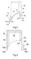
- Fig. 1 is an exploded perspective view of a door closing element 2 according to the invention (hereinafter referred to as closing element 2 called) shown, which forms the final element of a door of a household refrigerator in this example.
- closing element 2 the longitudinal, depth and height direction of the end element is indicated by a Cartesian coordinate system with the axes X, Y and Z.
- the end element 2 is designed in several parts and has at least two mutually corresponding, joinable profile elements 4, 6, which form in an assembled state, a total of the end element 2 forming profile structure unit.
- the one in which Fig. 1 lower profile element forms a connectable to a door edge of a door body base profile 4; and the other, in the Fig.
- the closure element 2 forms a connectable to the base profile 4 panel profile 6, which disguised in the assembled state, at least a portion of the base section 4.
- the closure element 2 has a strip-like, elongated shape.
- the total length of the closing element 2 in the longitudinal direction X preferably corresponds to the width of the door or of the door body to which or it should be connected later.
- the end member 2 is formed as an upper door edge termination. In another embodiment, however, it could also be designed as a lower door edge closure element.
- Both the base profile 4 and the trim profile 6 are each made of a thermoplastic material in an injection molding process. Both plastic materials are of the same type of material (or at least compatible with each other) and ultrasonically weldable, so that the profile elements 4, 6, as will be explained in more detail below, can be welded together.
- the base profile 4 are made of an opaque and the trim profile 6 made of a transparent thermoplastic material of the same plastic type.
- the trim profile 6 can also be made completely (or partially) from a translucent or opaque material or plastic material.
- the base profile 4 is half-shell-like or cap-shaped and adapted to be plugged onto a door edge and secured thereto. At its side portions it has in each case an accessible from its top insertion opening 8 for a pivot pin of a door hinge, or other means for connection to a door hinge mechanism, so that the closing element 2 is suitable both for doors in which the door pivot axis on the left side of the door lie as well as for those in which the pivot axis is located on the right side of the door.
- the unnecessary insertion opening 8 can be covered by a cap or the like.
- the base profile 4 also has an open hollow profile cross-section, which in the figure after Fig. 1 is open at the bottom.
- a sectional view along the plane II-II in Fig. 1 shows, has the cross-section of the base profile 4 in this area in the broadest sense, the shape of an inverted "U" with different lengths profile legs, which form a front wall 4a, a rear wall 4b and an intermediate upper wall 4c. 4c is in the in Fig. 2
- a sectional view taken along the plane III-III in Fig. 1 shows has the cross section essentially the shape of an approximately symmetrical, inverted "U".
- the lower edge regions of the base profile 4 are associated with a door edge and connectable to this.
- the profile contour of the edge regions or edges in this case corresponds substantially to the contour or profile contour of the associated door edge or the door edge of the usual manner forming sheets, plastic plates or door profiles.
- the base profile 4 at its lower edge door edge connection elements which may be configured, for example in the form of grooves 10a, grooves, claw-shaped areas, contact surfaces 10b, etc. and correspond correspondingly with the edge of the door.
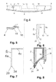
- Fig. 4 shows a frontal view of the base profile 4
- the recess 12 or this window extends over the entire depth of the base profile 4 in this area (see Fig. 1
- Beveled or curved side walls 14 surround the recess 12 in this case on three sides, so that the free passage cross section of the visible window-like recess 12 from the back extended to the front of the basic profile 4 out.
- Fig. 5 is a schematic sectional view taken along the plane VV in Fig. 4 shown.
- the base profile 4 has at a left and right side edge of a front portion 16 each have a groove 15th
- the trim profile 6 is also half-shell-like or trough or cap-shaped.
- Fig. 6 shows a section along the plane VI-VI in Fig. 1 represents, has the trim profile 6 in a central, the recess 12 and adjacent wall portions of the base profile 4 associated area a downwardly open hollow profile cross section, which has approximately the shape of an inverted "U"', with a front and rear wall 6a, 6b and a intermediate horizontal wall 6c.
- this U-shaped cross-section merges into a substantially L-shaped cross section, as shown in FIG Fig. 7 which shows a section along the plane VII-VII in Fig. 1 shows.
- the trim profile 6 is in the in Fig. 1 indicated by a large arrow direction, with its open side down, attachable to the back and corresponding receiving areas of the base profile 4. In the assembled or assembled with the base profile 4 state, the trim profile 6 completely covers the area of the viewing window or the recess 12.
- the trim profile 6 extends here also over lateral edges of the viewing window or the recess 12 across the adjacent front portions 16 and ceiling portions 18 of the base profile 4.
- rear portions of the trim profile 6 also extended beyond rear portions of the base profile 4 away. Parts of the cladding profile 6 therefore form part of the front, top and back of the final element 2 composed of the base profile 4 and the cladding profile 6.
- Fig. 8 shows a schematic sectional view along the in Fig. 1 and 4
- the trim profile 6 together with the base profile 6 is a substantially completely closed hollow profile cross-section, the extends over the entire recess 12 and laterally immediately adjacent areas away.
- the door edge closure element is particularly torsionally rigid and strong, and it can therefore be used profile elements with comparatively thin wall thicknesses, which also allows material savings. If a transparent or translucent cladding profile 6 is used, this forms a transparent "box" in the region of the viewing window or recess 12 due to its previously described profile cross-sectional shape.
- both profiles 4, 6 have guiding and positioning means for precisely matching these profile elements.
- the guiding and positioning means may in particular be mutually corresponding plug connections, for example in the form of spring and groove-like elements or regions or also pins, pins, tongues which can be inserted into correspondingly fitting openings or recesses, or in order other, in at least one direction producing a positive connection elements.
- These leadership and Positioning means can simultaneously serve as reinforcing elements for the thus assembled end element 2 and contribute, for example, to increase its bending and / or torsional rigidity and strength.
- a spring 24 of a laterally adjoining the lower edge 20, L-shaped downwardly angled region (see also 6 and 7 ) is inserted into a provided adjacent to the projection 22, corresponding groove 26 of the base section 4.
- the rear lower edge 28 of the wall 6a of the trim profile 6 rests on either the top of a rear portion of the central wall 14 or is at a small distance thereto, or has a similar tongue and groove arrangement as at the front edge 20.
- Die Side edges 6a1 of the front wall 6a of the trim profile 6 stuck with a spring (not shown) in the grooves 15 (see Fig. 1 and 3 ).
- side edges 6b1 of the rear wall 6b of the trim profile 6 are stuck in corresponding side grooves 30 (see FIG Fig. 1 ) on the back of the base profile 4.
- the side edges 6a1 and 6b1 are due to the shape of the grooves 15, 30, and the shape side edges 6a1, 6b1 itself, in the depth direction Y positively secured (see also Fig. 1 ).
- the base profile 4 and the trim profile 6 on connecting means. These connecting means are preferably formed integrally with these two profile elements 4, 6.
- the trim profile 6 has at its front and rear edge a plurality of integral, tongue-like tabs 32 which in corresponding slots 34 (see Fig. 1 and 3 ) in the basic profile 4 can be inserted.
- the tabs 32 and slots 34 also serve as guiding and positioning aids.
- a single slot 34 is shown in a diagrammatically cut-out area, as the slot 34 is concealed in the groove 26 (see FIG Fig. 2 ) lies.
- the length of these tabs 32 in the insertion direction is chosen so that they protrude slightly on the other side again from the base profile 4.
- these tabs 32 can then be welded to the material of the base profile 4 or at least be deformed so that they form a positive connection.
- the base profile 4 and the trim profile 6 are thus permanently connected to each other.
- the base profile 4 and the trim profile 6 on other Welded areas or interconnected by other suitable connection means, such as a latching connection, adhesive, etc.
- the base profile 4 and the trim profile 6 of this embodiment form in a joined state, at least at a front region and at the top of the end element 2 a flush outer contour.
- the profile contour of the base profile 4 is formed in the areas 16 and 18 at least corresponding to the respective wall thickness and the outer contour of the trim profile 6 of the desired outer contour of the finished closure element 2 offset inwardly or stepped (see Fig. 1 and 4 ).
- the depth of the gradations is partially slightly larger than the wall thickness of the trim profile 6 at the corresponding location, so that in these areas between the inner surface of the trim profile 6 and the outer surface of the base section 4 remains a small gap.
- Fig. 9 shows a schematic perspective rear view of the end element 2 of Fig. 1
- the rear wall 4b of the base profile 4 of lateral, rear profile edge portions 36 and a lower, rear edge 38 (see also FIGS. 2 and 3 ) of the same over a step 4d away in the depth direction Y back and forms over a majority of the back of the closing element 2 extending recess.
- the profile edge regions 36 and the edge 38 lie in this embodiment of a plane.
- the door closure element 2 according to the invention with its base profile 4 and trim profile 6 can be provided in the context of a door-end element sets, which can be used in a manufacturing process of substantially similar shaped household appliance doors in at least two different door variants, wherein the first variant has a first external appearance and the second variant has a second external appearance, which differs from the first external appearance.
- this set is used in a process for the production of household appliances with such different door variants.
- the set according to the invention comprises for series production, for example, a multiplicity of uniformly and / or identically shaped base profiles 4 and a plurality of trim profiles 6 of at least a first and a second one Trim profile type.
- These cladding profile types are identically shaped at least in a region which forms a joining region for joining to the base profile 4 and have a different external appearance.
- the first trim profile type is injection molded from an opaque thermoplastic material and the second type is a transparent one.
- these two panel profile types are completely identically shaped, so that the same injection mold or the same shape injection molds can be used for their production, and for example, only the plastic material or its properties must be varied.
- FIG. 10 is a schematic perspective view of an inventive household appliance in the form of a refrigerator 40 is shown.
- the refrigerator 40 has a case body 42 having a front opening and a door frame formed here from a front portion of the case body 42.
- a door 44 is pivotally mounted by means of a hinge member 45.
- the hinge member 45 has a pivot pin which in the insertion opening 8 (see, eg Fig. 1 ) of the closing element 2 can be inserted.
- the door 44 has a door body 46, the upper edge of which is provided with a door edge closing element 2 according to the invention, which extends over the entire width of the door 44.
- the height of the door 44 including the closing element 2 corresponds in this example substantially the height of the housing body.
- the width of the door 44 substantially corresponds to the width of the housing body 42.
- the base profile 4 of the end element 2 is made of an opaque plastic material, while the trim profile 6 is made of a transparent plastic material.
- the closing element 2 also has a central viewing window or a recess 12.
- the cladding profile 6 clad the viewing window 12 and also extends beyond even adjacent areas of the base profile 4. In the area of the viewing window 12, the cladding profile 6 simultaneously acts as a disc for the viewing window 12th
- a control panel 48 Arranged on an upper, central front area of the door frame or housing body 42 is a control panel 48 with device function and operating elements 50, which are, for example, an ON / OFF switch, operating status indicators (eg lights or displays), adjustment elements and the like can act.
- these elements 50 are behind the Viewing window 12 and are due to the transparency of the trim profile 6 well in the closed state of the door 44 well visible from outside through the viewing window 12 and located in the viewing window 12 area of the trim profile 6 therethrough or recognizable.
- a method according to the invention for producing refrigerators 40 with essentially identically shaped doors 44 in two different door variants, wherein the first variant has a first external appearance and the second variant has a second external appearance which differs from the first external appearance, will now be described. and a method according to the invention for producing such doors 44 by means of a door trim set according to the invention will be described.
- the respective refrigerators 40 on which these doors 44 are later mounted, in turn have a housing body 42 with a door frame, on which the respective associated door 44 is pivotally storable.
- the door body 46 used for producing the first and second door variant are uniform or substantially identical in shape, but it is basically sufficient that those door edge areas where the base section 4 is mounted, identical or substantially identical ,
- a uniform or identically shaped base profile 4 is provided in each case, but this provision need not be made simultaneously or at the same location.
- the door 44 is then pivotally attached to the housing body 42 and its door frame.
- the steps of providing the base profile 4 and the trim profile 6 can take place simultaneously, successively or in a different order and in particular the invention is not limited to a particular order in this regard.
- the method according to the invention can also have additional steps or intermediate steps for the respective door variant or the respective domestic appliance (here: refrigerator 40), for example for attaching sealing elements to the door 44 or the closing element 2, or e.g. for foaming the door body 46 and / or the closing element 2 with an insulating foam material.
- the number of required basic profiles 4 and trim profiles 6 (corresponding to the respective trim profile types) is to be matched to the number of doors or household appliances to be manufactured.
- connection of the closing element 2 was made to the edge of the door exclusively on the base profile 4, the invention is not limited to such a variant.
- the trim profile 6, depending on its shape and correspondingly corresponding shape of the base profile 4 have areas that are designed to be connected to the edge of the door.
- the inside of the viewing window 12 located in the substantially closed hollow profile cross-section can also be provided means for attaching device functional elements and / or device controls on which or in which then these functional or operating elements are to be arranged. If, for example, a touch control element is used as the control element, and if this is arranged close enough to a front inner surface of the trim profile 6 (or of the basic profile 4) from inside, then it can be replaced by the trim profile 6 (or the basic profile 4). be served away. Such operability can also be achieved if the operating element is arranged, for example, in an externally accessible opening of the trim profile 6 (or the basic profile 4).
- the terminating element 2 can also be open on its rear side, at least in some areas, so that, for example, a device-functional element and / or device operating element or a control panel 50 or the like arranged in the housing element 42 of the household appliance projects into the terminating element 2.
- decorative elements e.g. Adhesive sheets or the like, be attached, which are visible from the outside.
- decorative elements can also be attached to those areas of the base profile 4, over which the transparent or translucent trim profile 6 extends away and which are visible from the outside.
- a covering profile 6 or basic profile 4 can be produced, which integrally has both opaque and transparent or translucent areas.
- the basic profile 4 can basically be provided in different, but preferably equally shaped variants, a different external Appearance.
- the base profile 4 and the trim profile 6 can also be made of other suitable materials or combined with these.
Landscapes
- Engineering & Computer Science (AREA)
- Chemical & Material Sciences (AREA)
- Combustion & Propulsion (AREA)
- Physics & Mathematics (AREA)
- Mechanical Engineering (AREA)
- Thermal Sciences (AREA)
- General Engineering & Computer Science (AREA)
- Refrigerator Housings (AREA)
Applications Claiming Priority (1)
| Application Number | Priority Date | Filing Date | Title |
|---|---|---|---|
| ES200702175A ES2339623B1 (es) | 2007-07-23 | 2007-07-23 | Elemento de cierre de borde de puerta de una puerta de aparato domestico. |
Publications (2)
| Publication Number | Publication Date |
|---|---|
| EP2023063A2 true EP2023063A2 (fr) | 2009-02-11 |
| EP2023063A3 EP2023063A3 (fr) | 2015-09-30 |
Family
ID=39817129
Family Applications (1)
| Application Number | Title | Priority Date | Filing Date |
|---|---|---|---|
| EP08104676.5A Withdrawn EP2023063A3 (fr) | 2007-07-23 | 2008-07-09 | Elément de fermeture de bord de porte d'une porte d'appareil ménager |
Country Status (2)
| Country | Link |
|---|---|
| EP (1) | EP2023063A3 (fr) |
| ES (1) | ES2339623B1 (fr) |
Cited By (3)
| Publication number | Priority date | Publication date | Assignee | Title |
|---|---|---|---|---|
| WO2011026817A2 (fr) | 2009-09-01 | 2011-03-10 | Arcelik Anonim Sirketi | Porte de réfrigérateur haute résistance |
| DE102012012312A1 (de) * | 2012-05-18 | 2013-11-21 | Liebherr-Hausgeräte Ochsenhausen GmbH | Kühl- und/oder Gefriergerät |
| US10240858B2 (en) * | 2014-12-25 | 2019-03-26 | Bsh Hausgeraete Gmbh | Home appliance having drawer-type movable container with a handle |
Citations (1)
| Publication number | Priority date | Publication date | Assignee | Title |
|---|---|---|---|---|
| DE10302797A1 (de) | 2003-01-24 | 2004-07-29 | BSH Bosch und Siemens Hausgeräte GmbH | Kältegerät und Tür für ein Kältegerät |
Family Cites Families (6)
| Publication number | Priority date | Publication date | Assignee | Title |
|---|---|---|---|---|
| JP3404224B2 (ja) * | 1996-08-07 | 2003-05-06 | 松下冷機株式会社 | 冷蔵庫の温度調節装置 |
| DE10051075A1 (de) * | 2000-10-14 | 2002-04-25 | Aeg Hausgeraete Gmbh | Verfahren zum Herstellen unterschiedlicher Bedienblenden für Haushaltsgeräte und ein Haushaltsgerät |
| DE60214672T2 (de) * | 2001-02-13 | 2007-09-13 | Arcelik A.S., Tuzla | Haushaltsgerät |
| US6827410B2 (en) * | 2001-08-24 | 2004-12-07 | Thetford Corporation | Refrigerator door assembly and method of making same |
| JP2004044980A (ja) * | 2002-07-15 | 2004-02-12 | Toshiba Corp | 冷蔵庫扉 |
| DE202005014382U1 (de) * | 2005-09-12 | 2005-11-10 | BSH Bosch und Siemens Hausgeräte GmbH | Tür für ein Kältegerät |
-
2007
- 2007-07-23 ES ES200702175A patent/ES2339623B1/es not_active Revoked
-
2008
- 2008-07-09 EP EP08104676.5A patent/EP2023063A3/fr not_active Withdrawn
Patent Citations (1)
| Publication number | Priority date | Publication date | Assignee | Title |
|---|---|---|---|---|
| DE10302797A1 (de) | 2003-01-24 | 2004-07-29 | BSH Bosch und Siemens Hausgeräte GmbH | Kältegerät und Tür für ein Kältegerät |
Cited By (6)
| Publication number | Priority date | Publication date | Assignee | Title |
|---|---|---|---|---|
| WO2011026817A2 (fr) | 2009-09-01 | 2011-03-10 | Arcelik Anonim Sirketi | Porte de réfrigérateur haute résistance |
| WO2011026817A3 (fr) * | 2009-09-01 | 2011-07-14 | Arcelik Anonim Sirketi | Porte de réfrigérateur haute résistance |
| CN102483289A (zh) * | 2009-09-01 | 2012-05-30 | 阿塞里克股份有限公司 | 高强度冰箱门 |
| CN102483289B (zh) * | 2009-09-01 | 2015-02-18 | 阿塞里克股份有限公司 | 高强度冰箱门 |
| DE102012012312A1 (de) * | 2012-05-18 | 2013-11-21 | Liebherr-Hausgeräte Ochsenhausen GmbH | Kühl- und/oder Gefriergerät |
| US10240858B2 (en) * | 2014-12-25 | 2019-03-26 | Bsh Hausgeraete Gmbh | Home appliance having drawer-type movable container with a handle |
Also Published As
| Publication number | Publication date |
|---|---|
| EP2023063A3 (fr) | 2015-09-30 |
| ES2339623A1 (es) | 2010-05-21 |
| ES2339623B1 (es) | 2011-03-22 |
Similar Documents
| Publication | Publication Date | Title |
|---|---|---|
| EP2223030B1 (fr) | Porte d'appareil et appareil domestique doté d'une telle porte | |
| DE102005037891B4 (de) | Türgriff für einen Kühlschrank | |
| EP1702187B1 (fr) | Appareil refrigerant encastre | |
| DE10018186B4 (de) | Fahrzeugtür und Verfahren zu seiner Herstellung | |
| EP2235451B1 (fr) | Conteneur de stockage pour appareil frigorifique | |
| WO2008025658A2 (fr) | Appareil frigorifique intégré comportant un dispositif de distribution | |
| EP1913318A1 (fr) | Contenant modulaire pour produits refrigeres | |
| EP2467657B1 (fr) | Porte à poignée rapportée pour un appareil électroménager | |
| EP2023063A2 (fr) | Elément de fermeture de bord de porte d'une porte d'appareil ménager | |
| EP2163840B1 (fr) | Appareil ménager doté d'au moins une porte | |
| WO2011124446A2 (fr) | Compartiment de contre-porte pour un appareil frigorifique | |
| DE60011949T2 (de) | Verriegelungsbeschlag vom Typ Treibstangenbeschlag oder dergleichen | |
| EP1926952B1 (fr) | Porte pour appareil frigorifique | |
| DE602005002067T2 (de) | Tür- oder Fensterstruktur aus einem Metallprofilstab | |
| EP2457039A2 (fr) | Porte pour un boitier isolant | |
| DE10307536B4 (de) | Blende mit rechteckigem Tastenblock und Verfahren zu dessen Herstellung | |
| EP1576326A1 (fr) | Appareil frigorifique et porte con ue pour un appareil frigorifique | |
| DE10208063B4 (de) | Türabsteller für ein Kältegerät | |
| DE102017002640A1 (de) | Fensterrahmen für eine Fahrzeugfensterscheibe | |
| WO2000001992A1 (fr) | Compartiment de rangement | |
| EP2311347A1 (fr) | Elément de verrouillage pour verrouiller un intervalle entre un appareil incorporé et meuble entouré | |
| WO2002081990A1 (fr) | Bac de rangement pour appareils frigorifiques | |
| DE2029825A1 (de) | Profilelement | |
| EP3029244B1 (fr) | Dispositif de recouvrement pour un raccord | |
| DE3447801A1 (de) | Kastenfoermiges bauteil fuer elektrische schalt- und verteileranlagen |
Legal Events
| Date | Code | Title | Description |
|---|---|---|---|
| PUAI | Public reference made under article 153(3) epc to a published international application that has entered the european phase |
Free format text: ORIGINAL CODE: 0009012 |
|
| AK | Designated contracting states |
Kind code of ref document: A2 Designated state(s): AT BE BG CH CY CZ DE DK EE ES FI FR GB GR HR HU IE IS IT LI LT LU LV MC MT NL NO PL PT RO SE SI SK TR |
|
| AX | Request for extension of the european patent |
Extension state: AL BA MK RS |
|
| RAP1 | Party data changed (applicant data changed or rights of an application transferred) |
Owner name: BSH HAUSGERAETE GMBH |
|
| PUAL | Search report despatched |
Free format text: ORIGINAL CODE: 0009013 |
|
| AK | Designated contracting states |
Kind code of ref document: A3 Designated state(s): AT BE BG CH CY CZ DE DK EE ES FI FR GB GR HR HU IE IS IT LI LT LU LV MC MT NL NO PL PT RO SE SI SK TR |
|
| AX | Request for extension of the european patent |
Extension state: AL BA MK RS |
|
| RIC1 | Information provided on ipc code assigned before grant |
Ipc: F25D 23/02 20060101AFI20150824BHEP |
|
| 17P | Request for examination filed |
Effective date: 20160330 |
|
| RBV | Designated contracting states (corrected) |
Designated state(s): AT BE BG CH CY CZ DE DK EE ES FI FR GB GR HR HU IE IS IT LI LT LU LV MC MT NL NO PL PT RO SE SI SK TR |
|
| AKX | Designation fees paid |
Designated state(s): AT BE BG CH CY CZ DE DK EE ES FI FR GB GR HR HU IE IS IT LI LT LU LV MC MT NL NO PL PT RO SE SI SK TR |
|
| AXX | Extension fees paid |
Extension state: AL Extension state: BA Extension state: RS Extension state: MK |
|
| 17Q | First examination report despatched |
Effective date: 20180301 |
|
| GRAP | Despatch of communication of intention to grant a patent |
Free format text: ORIGINAL CODE: EPIDOSNIGR1 |
|
| INTG | Intention to grant announced |
Effective date: 20180830 |
|
| STAA | Information on the status of an ep patent application or granted ep patent |
Free format text: STATUS: THE APPLICATION IS DEEMED TO BE WITHDRAWN |
|
| 18D | Application deemed to be withdrawn |
Effective date: 20190110 |