EP0825453B1 - Procédé et dispositif pour le traitement de signaux représentatifs d'ondes réfléchies ou transmises par une structure volumique en vue d'effectuer une exploration et une analyse de cette structure - Google Patents
Procédé et dispositif pour le traitement de signaux représentatifs d'ondes réfléchies ou transmises par une structure volumique en vue d'effectuer une exploration et une analyse de cette structure Download PDFInfo
- Publication number
- EP0825453B1 EP0825453B1 EP97401409A EP97401409A EP0825453B1 EP 0825453 B1 EP0825453 B1 EP 0825453B1 EP 97401409 A EP97401409 A EP 97401409A EP 97401409 A EP97401409 A EP 97401409A EP 0825453 B1 EP0825453 B1 EP 0825453B1
- Authority
- EP
- European Patent Office
- Prior art keywords
- point
- memory
- waves
- reflected
- read
- Prior art date
- Legal status (The legal status is an assumption and is not a legal conclusion. Google has not performed a legal analysis and makes no representation as to the accuracy of the status listed.)
- Expired - Lifetime
Links
Images

Classifications
-
- G—PHYSICS
- G01—MEASURING; TESTING
- G01S—RADIO DIRECTION-FINDING; RADIO NAVIGATION; DETERMINING DISTANCE OR VELOCITY BY USE OF RADIO WAVES; LOCATING OR PRESENCE-DETECTING BY USE OF THE REFLECTION OR RERADIATION OF RADIO WAVES; ANALOGOUS ARRANGEMENTS USING OTHER WAVES
- G01S7/00—Details of systems according to groups G01S13/00, G01S15/00, G01S17/00
- G01S7/52—Details of systems according to groups G01S13/00, G01S15/00, G01S17/00 of systems according to group G01S15/00
- G01S7/52017—Details of systems according to groups G01S13/00, G01S15/00, G01S17/00 of systems according to group G01S15/00 particularly adapted to short-range imaging
- G01S7/52023—Details of receivers
- G01S7/52036—Details of receivers using analysis of echo signal for target characterisation
-
- G—PHYSICS
- G01—MEASURING; TESTING
- G01S—RADIO DIRECTION-FINDING; RADIO NAVIGATION; DETERMINING DISTANCE OR VELOCITY BY USE OF RADIO WAVES; LOCATING OR PRESENCE-DETECTING BY USE OF THE REFLECTION OR RERADIATION OF RADIO WAVES; ANALOGOUS ARRANGEMENTS USING OTHER WAVES
- G01S7/00—Details of systems according to groups G01S13/00, G01S15/00, G01S17/00
- G01S7/52—Details of systems according to groups G01S13/00, G01S15/00, G01S17/00 of systems according to group G01S15/00
- G01S7/52017—Details of systems according to groups G01S13/00, G01S15/00, G01S17/00 of systems according to group G01S15/00 particularly adapted to short-range imaging
- G01S7/52023—Details of receivers
- G01S7/52025—Details of receivers for pulse systems
- G01S7/52026—Extracting wanted echo signals
-
- G—PHYSICS
- G01—MEASURING; TESTING
- G01S—RADIO DIRECTION-FINDING; RADIO NAVIGATION; DETERMINING DISTANCE OR VELOCITY BY USE OF RADIO WAVES; LOCATING OR PRESENCE-DETECTING BY USE OF THE REFLECTION OR RERADIATION OF RADIO WAVES; ANALOGOUS ARRANGEMENTS USING OTHER WAVES
- G01S7/00—Details of systems according to groups G01S13/00, G01S15/00, G01S17/00
- G01S7/52—Details of systems according to groups G01S13/00, G01S15/00, G01S17/00 of systems according to group G01S15/00
- G01S7/52017—Details of systems according to groups G01S13/00, G01S15/00, G01S17/00 of systems according to group G01S15/00 particularly adapted to short-range imaging
- G01S7/52023—Details of receivers
- G01S7/52034—Data rate converters
Definitions
- the present invention relates to a method and a device for treatment of signals representative of waves reflected or transmitted by a structure volume in order to carry out an exploration and analysis of this structure.
- Conventional devices of this kind usually involve emission means which emit an incident wave in the medium to be examined and reception means possibly using all or part of the means emission (homodyne systems) which receive the waves reflected by the structures encountered by the incident wave. Means are also provided to transform to process the signals received by the reception means and present them in a form that can be used by the user, for example under the form of an image making it possible to locate the position of the obstacles generating reflections of the incident wave.
- the most common method for achieving these results is using impulse waves in a process of transmit a pulse in a given direction (shot), to detect the return echoes, to measure the time elapsed between transmission and reception and to deduce the distance and therefore the position of the obstacle which generated each echo. This firing process is then repeated for different directions, depending on a predetermined scanning law.
- the examination speed increases with the beam section explorer and with the cadence of impulses.
- the section of beam is limited by the required spatial resolution, while the cadence is itself limited by the time necessary for all the reflected echoes to return to the probe.
- the beam section can hardly exceed 2 mm, and the rate, taking into account of the reverberation phenomenon, must be less than 1000 Hz.
- this speed often proves to be too low. because it slows production, hence sometimes the need to have several installations working in parallel.
- each transmission / reception unit works in such a way independent and therefore receives separately the waves reflected by the obstacles intercepting the beam which is in its reception area.
- the information delivered by these issuing bodies are stored in the memories whose reading is performed in the opposite direction of writing.
- the read signals are then applied to a device for reconstituting the reflected wave field which comprises a plurality of emitting organs distributed according to a structure similar to that of the transmitting / receiving bodies of the above probe.
- the application of read signals to these organs transmitters is carried out in correspondence with the transmission to the memory of writing signals by the transmitting / receiving bodies.
- the purpose of the reconstitution device is to reproduce in an environment auxiliary the reflected wave field in order to reproduce an image of the object. with a resolution which depends on the wavelength of the incident wave and the dimension of the elements of the probe
- the incident wave is an ultrasonic wave
- the most simple is to form the image in an optically transparent medium and at the visualize using the Schlieren method.
- the image is collected on a third probe and the reading frequency is modulated so that the image of a structure is always "in point” when the corresponding signals arrive on this probe.
- US-A-4,817,434 describes a device comprising a address generator by sensor receiving element, this generator providing the address to be read from the field memory corresponding to the receiving element to obtain the signal corresponding to the image point to reconstruct.
- the image point is obtained by combining the signals read in the respective field memories of the detection elements, at the addresses indicated by the address generator, corresponding to the image point to reconstruct.
- This device only allows a frame rate relatively small. To eliminate this drawback, this document provides a complete processing chain per image point to reconstruct, This results in a device with a large number of components, and therefore extremely expensive.
- the invention therefore more particularly aims to remove these disadvantages.
- each point of the object to explore gives rise to a reflected wave which is stored in memory positions distributed in the form of arcs of hyperbolas whose characteristics depend the distance from the point to the probe and the radiation pattern of each element (these hyperbolas are theoretically reduced to the two asymptotes for the points located against the probe).
- All the lines of the field memory are therefore read in parallel and the values are added (either directly in numeric form or under analog form, after digital / analog conversion) to give birth of a voltage whose value is entered into a memory "image" comprising a plurality of points, to each of which corresponds a law of reading for example hyperbolic whose parameters depend on coordinates of this point.
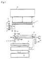
- the device shown in FIG. 1 can be used in switchgear ultrasound working in pulse reflection, for non-destructive testing materials or medical imagery.
- probe 1 consisting of a linear strip made up of a plurality of transmitter / receiver elements D 1 to D n of small dimension (1 mm), for example 128 in number. As a result, the same probe 1 is used for transmission and reception.
- Each element D 1 to D n is connected, on the one hand, to a zone, here a line L 1 ... L n respectively of a field memory MC, by means of a preamplifier A and d an analog / digital converter CAN and, on the other hand, to a transmitter E, via two diodes 2, 3 mounted head to tail, having a conduction threshold for example of the order of a fraction of a volt .
- the diodes 2, 3 associated with all the transmitter / receiver elements D 1 to D 9 are largely conductive and behave like short circuits, so that all the elements D 1 to D 9 are excited in parallel by the emitter E and therefore produce a plane wave.
- each element D 1 to D 9 works independently and attacks the preamplifier A to which it is connected. Indeed, the signals detected by the elements are weak (a few tens of millivolts).
- This arrangement also has the advantage of reducing input noise by insulating the preamplifiers A of the transmission circuit
- Each preamplifier A then drives a corresponding analog / digital converter CAN and the digitized signals are stored in the memory lines L 1 to L n , at write addresses supplied by an address memory MA itself addressed by a counter.
- CR controlled by a CK clock. This counter CR and this clock CK are common to all the address memories MA associated with the memory lines L 1 to L n .
- the number No of memory positions used during the write operation is chosen from among the powers of two, for example, 512, 1024, etc.
- the memories L 1 to L n are switched to the read position, by means of a flip-flop B controlled by bit 10 of the counter CR.
- This calculation is carried out as follows from the address 512, the counter CR addresses a position P'ij of a memory Mi (FIG. 2). At each point P '11 to P'nm of this memory Mi is made to correspond a position P 11 to P nm of the examined object O, so that this memory "image" Mi can be operated subsequently to provide an image of the object O.
- scanning can start at the same time as the program. If we work with a relay acoustic, the start of scanning can be delayed by a time equal to Round trip in the relay.
- the values read in the various memories are added in an adder circuit S and sent to the selected position of the memory Mi (for example the position P'ij).
- the information in the Mi memory can be used in different ways.
- This information can also be processed, for example, by circuits logic to identify and record the nature of detected faults in the case of non-destructive testing
- the address memories MA can be read only memories (ROM, PROM, EPROM) programmed once and for all. However, it is preferable. both in terms of speed and flexibility of operation. to use reprogrammable memories once in place, for example RAM.
- Programming can then be done at the time of start-up.
- the calculation preliminary can be done by a mini-computer depending on the conditions and the model of probe used. Data can also be precomputed and stored on discs or on PROM.
- the results are then transferred sequentially to the memory MA by a conventional method. This transfer can be very fast (a few seconds).
- x be the distance separating element D 1 from probe 1 and element Di directly above point Pij, and c the speed of sound in the object medium.
- the writing frequency is designated by f and if writing starts at the same time time that the emission, the reflected signal will be stored in the cell of the MC field memory located on the abscissa x, at position f. t (x).
- the wave does not propagate perpendicular to the probe (probing under inclined incidence) or if the wave is not plane (circular wave in the case of a sector survey) the calculation is done in a very similar way, only changes the time put by the wave to reach a point Pij. This time no longer depends only of d but also of the lateral position of the point Pij relative to the probe 1. If the wave is tilted, the time varies linearly depending on the position lateral Xp, the time taken by the emitted wave to reach the point Pij being equal at (d. cos ( ⁇ ) - Xp. sin ⁇ ) / C, ⁇ being the angle of the emitted beam with respect to the normal to probe 1.
- each point gives rise to a wave reflected in duration as it will be memorized in almost all positions of memory lines MC. and information corresponding to different points will overlap.
- This reading can be done by gradually changing the shape of the reading hyperbolas, or by "focusing" on an area located given distance.
- the digitization of the signal must then be done on a number of more levels high, to allow good discrimination of different information.
- the ultrasonic signal is memorized before detection, therefore at high frequency level.
- the sampling frequency must be at least three times the ultrasonic frequency, for example, 10 MHz for a 3 MHz ultrasonic wave.
- the maximum round trip time is approximately 60 microseconds, or 600 points sampled on each line.
- the calculation is reduced here to a simple reading of memory followed by an addition.
- the memorization of the field will have lasted 60 microseconds, and the total time acquisition of an image will therefore be equal to 660 microseconds, the rate image may be greater than 1000 Hz.
- the method according to the invention has numerous advantages over sequential processes.
- the examination speed can be multiplied by 50 or 100 compared to the process sequential, which is considerable.
- the speed of the system opens the way to many applications, for example three-dimensional imagery and Doppler imagery.
- Three-dimensional imagery can be easily obtained using a probe matrix, but the electronics are very heavy, because the number of elements of a classic array probe is high. However, it is possible to reduce substantially the number of elements using a random distribution of these last on the surface of the probe, which allows a greater spacing elements without the parasitic lobes becoming too large.
- a linear probe a series of planes can be quickly recorded by moving the cutting plane between each shot. At a rate of 100 Hz. 100 shots of cuts can be memorized in 1/10 second. Memories can be then used to obtain a three-dimensional view, or a sectional view in any plane.
- Doppler imaging results from the fact that successive images can be compared.
- the signal high frequency being memorized, very small differences between two images can be detected (by subtraction, for example) and highlighted.
- the system works with a very large numerical aperture. In practice, the spatial resolution is limited only by the larger of the two values: wavelength - dimension of an element. Thus, in the example cited, the greater of these two values is the wavelength, ie 2 mm. With a frequency of 10 MHz, the larger of the two values would be the dimension of an element, here 1 mm.
- the system can work with shape emission wave fronts any (planes, inclined planes, cylindrical). Just calculate in each case forms the reading hyperbolas according to their position.
Description
- l'émission dans ladite structure d'une onde incidente,
- la réception des ondes réfléchies ou transmises par les structures rencontrées par l'onde incidente à l'intérieur de l'objet, par une pluralité d'éléments de détection indépendants les uns des autres,
- la mémorisation après numérisation des signaux délivrés par les moyens de détection, dans une mémoire de champ comprenant une ligne respective par élément de détection, et
- la reconstitution et/ou l'analyse de la structure de l'objet à partir des informations lues dans la mémoire de champ, dans laquelle sont calculées pour chaque point de l'objet, les positions de la mémoire de champ contenant les signaux détectés par les éléments de détection, correspondant aux ondes réfléchies ou transmises par ce point, ces positions étant calculées à l'aide d'une loi d'adressage dont les paramètres dépendent de la position de ce point par rapport aux éléments de détection, et dans laquelle pour chaque point, les lignes de la mémoire de champ sont lues aux positions respectives calculées au préalable pour ce point, et stockées dans des mémoires d'adressage respectivement associées auxdites lignes de la mémoire de champs et un calcul est appliqué aux informations lues pour ce point pour obtenir un résultat représentatif de l'importance de l'onde réfléchie ou transmise par ce point, lors de ce calcul, toutes les lignes de la mémoire de champ étant lues en parallèle pour chaque point aux positions indiquées pour ce point respectivement par les mémoires d'adressage associées, le calcul du résultat étant ensuite appliqué à toutes les valeurs lues dans la mémoire de champ, ce résultat étant ensuite traité ou mémorisé dans une mémoire spécifique,
- l'onde incidente comporte au moins une alternance complète,
- la fréquence d'échantillonnage utilisée pour la numérisation des signaux de détection est égale à au moins trois fois la fréquence de l'onde incidente
- lors de la susdite phase de reconstitution, on effectue la lecture dans la mémoire de champs des valeurs correspondant aux alternances positives et négatives,
- on compense les premières valeurs par les secondes valeurs de manière à enregistrer dans la susdite mémoire spécifique une valeur compensée présentant un rapport signal/bruit amélioré.
Claims (15)
- Procédé pour le traitement de signaux représentatifs d'ondes réfléchies ou transmises par un objet (O), en vue d'effectuer une exploration et une analyse de la structure de cet objet, ce procédé comprenant les étapes suivantes :caractérisé en ce que :l'émission dans ladite structure d'une onde incidente,la réception des ondes réfléchies ou transmises par les structures rencontrées par l'onde incidente à l'intérieur de l'objet (O), par une pluralité d'éléments de détection (D1 à Dn) indépendants les uns des autres,la mémorisation après numérisation des signaux délivrés par les moyens de détection, dans une mémoire de champ (MC) comprenant une ligne (L1 à Ln) respective par élément de détection (D1 à Dn), etla reconstitution et/ou l'analyse de la structure de l'objet (O) à partir des informations lues dans la mémoire de champ (MC), dans laquelle sont calculées pour chaque point (Pij) de l'objet (O), les positions de la mémoire de champ contenant les signaux détectés par les éléments de détection (D1 à Dn), correspondant aux ondes réfléchies ou transmises par ce point (Pij), ces positions étant calculées à l'aide d'une loi d'adressage dont les paramètres dépendent de la position de ce point par rapport aux éléments de détection, et dans laquelle pour chaque point (Pij), les lignes (L1 à Ln) de la mémoire de champ (MC) sont lues aux positions respectives calculées au préalable pour ce point (Pij), et stockées dans des mémoires d'adressage (MA) respectivement associées auxdites lignes (L1 à Ln) de la mémoire de champs (MC) et un calcul est appliqué aux informations lues pour ce point pour obtenir un résultat (Vp) représentatif de l'importance de l'onde réfléchie ou transmise par ce point, lors de ce calcul, toutes les lignes (L1 à Ln) de la mémoire de champ (MC) étant lues en parallèle pour chaque point (Pij) aux positions indiquées pour ce point respectivement par les mémoires d'adressage (MA) associées, le calcul du résultat (Vp) étant ensuite appliqué à toutes les valeurs lues dans la mémoire de champ (MC), ce résultat étant ensuite traité ou mémorisé dans une mémoire spécifique,l'onde incidente comporte au moins une alternance complète,la fréquence d'échantillonnage utilisée pour la numérisation des signaux de détection est égale à au moins trois fois la fréquence de l'onde incidentelors de la susdite phase de reconstitution, on effectue la lecture dans la mémoire de champs des valeurs correspondant aux alternances positives et négatives,on compense les premières valeurs par les secondes valeurs de manière à enregistrer dans la susdite mémoire spécifique une valeur compensée présentant un rapport signal/bruit amélioré.
- Procédé selon la revendication 1,
le résultat (Vp) pour chaque point (Pij) est mémorisé dans une mémoire image (Mi) comprenant une pluralité de positions (P1' à Pn') correspondant respectivement aux points (Pij). - Procédé selon la revendication 1 ou 2,
caractérisé en ce que la susdite loi d'adressage est une loi hyperbolique, et le calcul appliqué aux valeurs lues dans la mémoire champ (MC) est une addition. - Procédé selon l'une des revendications précédentes,
caractérisé en ce que plusieurs lois d'adressage de lecture sont associées à chaque point (P1 à Pn) de la mémoire image. - Procédé selon l'une des revendications précédentes,
caractérisé en ce que les susdites ondes incidentes sont émises sous la forme d'impulsions. - Procédé selon l'une des revendications 1 à 3,
caractérisé en ce que les ondes incidentes sont émises sous la forme de trains d'ondes ou d'une émission continue, la loi d'adressage étant alors choisie de façon à mettre en évidence les points réfléchissants situés à une distance prédéterminée. - Procédé selon l'une des revendications précédentes,
caractérisé en ce que l'émission des ondes incidentes et la réception des ondes réfléchies s'effectuent par les mêmes moyens. - Procédé selon l'une des revendications 1 à 6,
caractérisé en ce que l'émission des ondes incidentes et la réception des ondes réfléchies ou transmises s'effectuent à l'aide de moyens distincts. - Procédé selon l'une des revendications précédentes,
caractérisé en ce que les fronts des ondes incidentes sont plans. - Procédé selon la revendication 1,
caractérisé en ce que les ondes incidentes sont composées de faisceaux directifs et/ou focalisés, ne se recouvrant pas, ces faisceaux étant déplacés au cours d'émissions successives de façon à couvrir toute la structure explorée. - Procédé selon la revendication 1,
caractérisé en ce que les susdites ondes incidentes sont engendrées à l'aide d'un réseau linéaire d'organes d'émission / réception indépendants. - Procédé selon la revendication 1,
caractérisé en ce que les ondes incidentes sont engendrées à l'aide d'organes d'émission / réception disposés selon une configuration matricielle. - Procédé selon la revendication 1,
caractérisé en ce que les ondes incidentes sont engendrées à l'aide d'organes d'émission / réception disposés aléatoirement. - Dispositif pour la mise en oeuvre du procédé selon la revendication 1,
caractérisé en ce qu'il comprend une sonde (1) composée d'une pluralité d'éléments émetteur / récepteur (D1 à Dn) reliés chacun, d'une part, à un émetteur (E), par l'intermédiaire de deux diodes à seuil de conduction (2, 3) montées tête-bêche et, d'autre part, à un convertisseur analogique I numérique (CAN) dont la sortie est reliée à l'entrée d'écriture d'une ligne respective (L1 à Ln) d'une mémoire de champ (MC), dont la lecture est commandée par une mémoire d'adressage (MA) respective pilotée par une horloge (CK) via un compteur (CR), les sorties de lecture respectives des lignes (L1 à Ln) de la mémoire de champ (MC) étant connectées à un additionneur (S) dont la sortie est reliée à l'entrée d'écriture d'une mémoire image (Mi) pilotée par le susdit compteur (CR). - Dispositif selon la revendication 14,
caractérisé en ce que la susdite mémoire image (Mi) est exploitée par un dispositif d'affichage.
Applications Claiming Priority (2)
| Application Number | Priority Date | Filing Date | Title |
|---|---|---|---|
| FR9610325 | 1996-08-14 | ||
| FR9610325A FR2752461B1 (fr) | 1996-08-14 | 1996-08-14 | Procede et dispositif pour le traitement de signaux representatifs d'ondes reflechies ou transmises par une structure volumique en vue d'effectuer une exploration et une analyse de cette structure |
Publications (2)
| Publication Number | Publication Date |
|---|---|
| EP0825453A1 EP0825453A1 (fr) | 1998-02-25 |
| EP0825453B1 true EP0825453B1 (fr) | 2001-08-01 |
Family
ID=9495138
Family Applications (1)
| Application Number | Title | Priority Date | Filing Date |
|---|---|---|---|
| EP97401409A Expired - Lifetime EP0825453B1 (fr) | 1996-08-14 | 1997-06-19 | Procédé et dispositif pour le traitement de signaux représentatifs d'ondes réfléchies ou transmises par une structure volumique en vue d'effectuer une exploration et une analyse de cette structure |
Country Status (11)
| Country | Link |
|---|---|
| US (1) | US6023660A (fr) |
| EP (1) | EP0825453B1 (fr) |
| JP (1) | JPH10123109A (fr) |
| CN (1) | CN1187612C (fr) |
| AT (1) | ATE203833T1 (fr) |
| CA (1) | CA2211419C (fr) |
| DE (1) | DE69705900T2 (fr) |
| ES (1) | ES2162213T3 (fr) |
| FR (1) | FR2752461B1 (fr) |
| MY (1) | MY125709A (fr) |
| RU (1) | RU2178880C2 (fr) |
Cited By (1)
| Publication number | Priority date | Publication date | Assignee | Title |
|---|---|---|---|---|
| US10025272B2 (en) | 2013-01-25 | 2018-07-17 | General Electric Company | Ultrasonic holography imaging system and method |
Families Citing this family (8)
| Publication number | Priority date | Publication date | Assignee | Title |
|---|---|---|---|---|
| US6685645B1 (en) * | 2001-10-20 | 2004-02-03 | Zonare Medical Systems, Inc. | Broad-beam imaging |
| FR2855271B1 (fr) * | 2003-05-22 | 2006-01-21 | Jacques Dory | Procede pour l'exploration et l'analyse d'une structure volumique |
| DE10334902B3 (de) * | 2003-07-29 | 2004-12-09 | Nutronik Gmbh | Verfahren und Schaltungsanordnung zur Verarbeitung von Signalen, die bei der zerstörungsfreien Prüfung von Gegenständen durch Reflexion von Ultraschallwellen erzeugt werden |
| US20070112528A1 (en) * | 2005-10-25 | 2007-05-17 | Scott Farrell | Leak detection system and method |
| JP4984519B2 (ja) * | 2005-12-19 | 2012-07-25 | Jfeスチール株式会社 | 超音波による金属材料の断面検査方法及び装置 |
| US9213086B2 (en) * | 2007-05-14 | 2015-12-15 | Fujifilm Sonosite, Inc. | Computed volume sonography |
| US8235902B2 (en) * | 2007-09-11 | 2012-08-07 | Focus Surgery, Inc. | System and method for tissue change monitoring during HIFU treatment |
| US9639056B2 (en) * | 2013-09-17 | 2017-05-02 | General Electric Company | Acoustical holography with multi-level square wave excitation signals |
Family Cites Families (13)
| Publication number | Priority date | Publication date | Assignee | Title |
|---|---|---|---|---|
| US4165649A (en) * | 1975-02-13 | 1979-08-28 | Southwest Research Institute | Apparatus and method for ultrasonic inspection of highly attenuative materials |
| JPS57179745A (en) * | 1981-04-30 | 1982-11-05 | Fujitsu Ltd | Method and device for measuring material property by ultrasonic wave |
| JPS60116345A (ja) * | 1983-11-30 | 1985-06-22 | 富士通株式会社 | 超音波診断装置 |
| JPH0619471B2 (ja) * | 1984-03-30 | 1994-03-16 | 株式会社日立製作所 | 地中物体の識別方法および装置 |
| JPS6111658A (ja) * | 1984-06-28 | 1986-01-20 | Terumo Corp | 超音波測定方法およびその装置 |
| US4787393A (en) * | 1985-11-20 | 1988-11-29 | Matsushita Electric Industrial Co., Ltd. | Ultrasonic tomographic with alternate image scaling |
| JPH02263180A (ja) * | 1989-04-03 | 1990-10-25 | Toshiba Corp | 開口合成処理装置 |
| JPH0640096B2 (ja) * | 1989-05-22 | 1994-05-25 | 工業技術院長 | 微小散乱体間隔空間分布測定方法および装置 |
| DE69131798T2 (de) * | 1990-06-12 | 2000-05-11 | Univ Florida | Verfahren zur automatischen qantisierung von digitalisierten bilddaten |
| JP2757268B2 (ja) * | 1990-11-16 | 1998-05-25 | 日本電信電話株式会社 | 不可視物体探査方法 |
| JPH04188058A (ja) * | 1990-11-21 | 1992-07-06 | Olympus Optical Co Ltd | 超音波探傷装置 |
| JP2785636B2 (ja) * | 1993-02-25 | 1998-08-13 | 株式会社エス.エス.ビー | 生体組織多次元可視装置 |
| US5347495A (en) * | 1993-04-30 | 1994-09-13 | Milltronics Ltd. | Matching transformer for ultrasonic transducer |
-
1996
- 1996-08-14 FR FR9610325A patent/FR2752461B1/fr not_active Expired - Fee Related
-
1997
- 1997-06-19 EP EP97401409A patent/EP0825453B1/fr not_active Expired - Lifetime
- 1997-06-19 AT AT97401409T patent/ATE203833T1/de not_active IP Right Cessation
- 1997-06-19 ES ES97401409T patent/ES2162213T3/es not_active Expired - Lifetime
- 1997-06-19 DE DE69705900T patent/DE69705900T2/de not_active Expired - Fee Related
- 1997-06-26 MY MYPI97002887A patent/MY125709A/en unknown
- 1997-07-15 CA CA002211419A patent/CA2211419C/fr not_active Expired - Fee Related
- 1997-08-08 RU RU97114148/09A patent/RU2178880C2/ru not_active IP Right Cessation
- 1997-08-13 US US08/910,878 patent/US6023660A/en not_active Expired - Fee Related
- 1997-08-13 CN CNB97117640XA patent/CN1187612C/zh not_active Expired - Fee Related
- 1997-08-14 JP JP9219578A patent/JPH10123109A/ja active Pending
Cited By (1)
| Publication number | Priority date | Publication date | Assignee | Title |
|---|---|---|---|---|
| US10025272B2 (en) | 2013-01-25 | 2018-07-17 | General Electric Company | Ultrasonic holography imaging system and method |
Also Published As
| Publication number | Publication date |
|---|---|
| ES2162213T3 (es) | 2001-12-16 |
| FR2752461B1 (fr) | 1998-11-06 |
| DE69705900D1 (de) | 2001-09-06 |
| US6023660A (en) | 2000-02-08 |
| CN1176386A (zh) | 1998-03-18 |
| CA2211419C (fr) | 2009-02-10 |
| DE69705900T2 (de) | 2002-04-04 |
| EP0825453A1 (fr) | 1998-02-25 |
| RU2178880C2 (ru) | 2002-01-27 |
| CN1187612C (zh) | 2005-02-02 |
| JPH10123109A (ja) | 1998-05-15 |
| ATE203833T1 (de) | 2001-08-15 |
| CA2211419A1 (fr) | 1998-02-14 |
| MY125709A (en) | 2006-08-30 |
| FR2752461A1 (fr) | 1998-02-20 |
Similar Documents
| Publication | Publication Date | Title |
|---|---|---|
| EP0591061B1 (fr) | Procédé et dispositif d'examen acoustique à retournement temporel | |
| EP0872742B1 (fr) | Procédé et dispositif pour le traitement de signaux représentatifs d'ondes réfléchies, transmises ou réfractées par une structure volumique en vue d'effectuer une exploration et une analyse de cette structure | |
| EP0541434B1 (fr) | Procédé et dispositif de contrÔle interne de pièces par ultrasons | |
| US7089796B2 (en) | Time-reversed photoacoustic system and uses thereof | |
| EP0383650A1 (fr) | Procédé et dispositif de repérage et de focalisation d'ondes | |
| EP0709673A1 (fr) | Dispositif de contrÔle non destructif d'objets tubulaires creux par ultrasons | |
| FR2851662A1 (fr) | Procede et dispositif de detection de discontinuites dans un milieu | |
| EP0124442B1 (fr) | Procédé et dispositif d'holographie acoustique utilisant un faisceau ultrasonore limité dans l'espace | |
| EP0543445A1 (fr) | Appareil d'examen de milieux par échographie ultrasonore | |
| EP0825453B1 (fr) | Procédé et dispositif pour le traitement de signaux représentatifs d'ondes réfléchies ou transmises par une structure volumique en vue d'effectuer une exploration et une analyse de cette structure | |
| EP0718639A1 (fr) | Procédé de détection d'objets répartis dans une zone de terrain et dispositif mettant en oeuvre un tel procédé | |
| EP0718638B1 (fr) | Procédé de détection d'objets répartis dans une zone de terrain ou de détermination des caractéristiques de propagation d'une onde acoustique dans le sol et dispositif mettant en oeuvre de tels procédés | |
| FR2558956A1 (fr) | Procede et dispositif de recherche et de caracterisation de defauts d'une structure metallique connue immergee | |
| EP0196714B1 (fr) | Procédé et appareil d'exploration de milieux par échographie ultrasonore | |
| EP4083659B1 (fr) | Dispositif et procédé de traitement du signal issus d'un ensemble de transducteurs ultrasonores | |
| WO2004104632A1 (fr) | Procede pour l'exploration et l'analyse d'une structure volumique | |
| EP0040566A1 (fr) | Dispositif d'échographie à focalisation dynamique et à balayage sectoriel | |
| FR2908516A1 (fr) | Procede et dispositif d'emission et/ou de reception d'ondes ultrasonores guidees, selon un mode de propagation preponderant, choisi parmi differents modes possibles | |
| WO1997004333A1 (fr) | Procede et dispositif d'imagerie a traitement parallele de donnees | |
| FR2507324A1 (fr) | Procede de localisation de source acoustique, dispositif mettant en oeuvre un tel procede, et appareil de saisie de donnees graphiques en faisant application | |
| FR2908517A1 (fr) | Procede et dispositif d'emission et/ou de reception d'ondes ultrasonores guidees, selon un mode de propagation unique |
Legal Events
| Date | Code | Title | Description |
|---|---|---|---|
| PUAI | Public reference made under article 153(3) epc to a published international application that has entered the european phase |
Free format text: ORIGINAL CODE: 0009012 |
|
| 17P | Request for examination filed |
Effective date: 19970703 |
|
| AK | Designated contracting states |
Kind code of ref document: A1 Designated state(s): AT DE ES GB IT NL SE |
|
| AKX | Designation fees paid |
Free format text: AT DE ES GB IT NL SE |
|
| RBV | Designated contracting states (corrected) |
Designated state(s): AT DE ES GB IT NL SE |
|
| 17Q | First examination report despatched |
Effective date: 19991201 |
|
| GRAG | Despatch of communication of intention to grant |
Free format text: ORIGINAL CODE: EPIDOS AGRA |
|
| GRAG | Despatch of communication of intention to grant |
Free format text: ORIGINAL CODE: EPIDOS AGRA |
|
| GRAH | Despatch of communication of intention to grant a patent |
Free format text: ORIGINAL CODE: EPIDOS IGRA |
|
| GRAH | Despatch of communication of intention to grant a patent |
Free format text: ORIGINAL CODE: EPIDOS IGRA |
|
| GRAA | (expected) grant |
Free format text: ORIGINAL CODE: 0009210 |
|
| AK | Designated contracting states |
Kind code of ref document: B1 Designated state(s): AT DE ES GB IT NL SE |
|
| PG25 | Lapsed in a contracting state [announced via postgrant information from national office to epo] |
Ref country code: AT Free format text: LAPSE BECAUSE OF FAILURE TO SUBMIT A TRANSLATION OF THE DESCRIPTION OR TO PAY THE FEE WITHIN THE PRESCRIBED TIME-LIMIT Effective date: 20010801 |
|
| REF | Corresponds to: |
Ref document number: 203833 Country of ref document: AT Date of ref document: 20010815 Kind code of ref document: T |
|
| GBT | Gb: translation of ep patent filed (gb section 77(6)(a)/1977) |
Effective date: 20010801 |
|
| REF | Corresponds to: |
Ref document number: 69705900 Country of ref document: DE Date of ref document: 20010906 |
|
| ITF | It: translation for a ep patent filed |
Owner name: ING. A. GIAMBROCONO & C. S.R.L. |
|
| PG25 | Lapsed in a contracting state [announced via postgrant information from national office to epo] |
Ref country code: SE Free format text: LAPSE BECAUSE OF FAILURE TO SUBMIT A TRANSLATION OF THE DESCRIPTION OR TO PAY THE FEE WITHIN THE PRESCRIBED TIME-LIMIT Effective date: 20011101 |
|
| REG | Reference to a national code |
Ref country code: ES Ref legal event code: FG2A Ref document number: 2162213 Country of ref document: ES Kind code of ref document: T3 |
|
| REG | Reference to a national code |
Ref country code: GB Ref legal event code: IF02 |
|
| PLBE | No opposition filed within time limit |
Free format text: ORIGINAL CODE: 0009261 |
|
| STAA | Information on the status of an ep patent application or granted ep patent |
Free format text: STATUS: NO OPPOSITION FILED WITHIN TIME LIMIT |
|
| 26N | No opposition filed | ||
| PGFP | Annual fee paid to national office [announced via postgrant information from national office to epo] |
Ref country code: ES Payment date: 20080603 Year of fee payment: 12 |
|
| PGFP | Annual fee paid to national office [announced via postgrant information from national office to epo] |
Ref country code: IT Payment date: 20080527 Year of fee payment: 12 |
|
| PGFP | Annual fee paid to national office [announced via postgrant information from national office to epo] |
Ref country code: NL Payment date: 20080626 Year of fee payment: 12 Ref country code: DE Payment date: 20080821 Year of fee payment: 12 |
|
| PGFP | Annual fee paid to national office [announced via postgrant information from national office to epo] |
Ref country code: GB Payment date: 20080609 Year of fee payment: 12 |
|
| GBPC | Gb: european patent ceased through non-payment of renewal fee |
Effective date: 20090619 |
|
| NLV4 | Nl: lapsed or anulled due to non-payment of the annual fee |
Effective date: 20100101 |
|
| PG25 | Lapsed in a contracting state [announced via postgrant information from national office to epo] |
Ref country code: GB Free format text: LAPSE BECAUSE OF NON-PAYMENT OF DUE FEES Effective date: 20090619 |
|
| PG25 | Lapsed in a contracting state [announced via postgrant information from national office to epo] |
Ref country code: DE Free format text: LAPSE BECAUSE OF NON-PAYMENT OF DUE FEES Effective date: 20100101 |
|
| PG25 | Lapsed in a contracting state [announced via postgrant information from national office to epo] |
Ref country code: NL Free format text: LAPSE BECAUSE OF NON-PAYMENT OF DUE FEES Effective date: 20100101 |
|
| REG | Reference to a national code |
Ref country code: ES Ref legal event code: FD2A Effective date: 20090620 |
|
| PG25 | Lapsed in a contracting state [announced via postgrant information from national office to epo] |
Ref country code: ES Free format text: LAPSE BECAUSE OF NON-PAYMENT OF DUE FEES Effective date: 20090620 |
|
| PG25 | Lapsed in a contracting state [announced via postgrant information from national office to epo] |
Ref country code: IT Free format text: LAPSE BECAUSE OF NON-PAYMENT OF DUE FEES Effective date: 20090619 |