EP0825453B1 - Method and apparatus for processing signals representative of waves which have been reflected by or transmitted through a volume structure, in order to enable exploration and analysis of said structure - Google Patents
Method and apparatus for processing signals representative of waves which have been reflected by or transmitted through a volume structure, in order to enable exploration and analysis of said structure Download PDFInfo
- Publication number
- EP0825453B1 EP0825453B1 EP97401409A EP97401409A EP0825453B1 EP 0825453 B1 EP0825453 B1 EP 0825453B1 EP 97401409 A EP97401409 A EP 97401409A EP 97401409 A EP97401409 A EP 97401409A EP 0825453 B1 EP0825453 B1 EP 0825453B1
- Authority
- EP
- European Patent Office
- Prior art keywords
- point
- memory
- waves
- reflected
- read
- Prior art date
- Legal status (The legal status is an assumption and is not a legal conclusion. Google has not performed a legal analysis and makes no representation as to the accuracy of the status listed.)
- Expired - Lifetime
Links
Images

Classifications
-
- G—PHYSICS
- G01—MEASURING; TESTING
- G01S—RADIO DIRECTION-FINDING; RADIO NAVIGATION; DETERMINING DISTANCE OR VELOCITY BY USE OF RADIO WAVES; LOCATING OR PRESENCE-DETECTING BY USE OF THE REFLECTION OR RERADIATION OF RADIO WAVES; ANALOGOUS ARRANGEMENTS USING OTHER WAVES
- G01S7/00—Details of systems according to groups G01S13/00, G01S15/00, G01S17/00
- G01S7/52—Details of systems according to groups G01S13/00, G01S15/00, G01S17/00 of systems according to group G01S15/00
- G01S7/52017—Details of systems according to groups G01S13/00, G01S15/00, G01S17/00 of systems according to group G01S15/00 particularly adapted to short-range imaging
- G01S7/52023—Details of receivers
- G01S7/52036—Details of receivers using analysis of echo signal for target characterisation
-
- G—PHYSICS
- G01—MEASURING; TESTING
- G01S—RADIO DIRECTION-FINDING; RADIO NAVIGATION; DETERMINING DISTANCE OR VELOCITY BY USE OF RADIO WAVES; LOCATING OR PRESENCE-DETECTING BY USE OF THE REFLECTION OR RERADIATION OF RADIO WAVES; ANALOGOUS ARRANGEMENTS USING OTHER WAVES
- G01S7/00—Details of systems according to groups G01S13/00, G01S15/00, G01S17/00
- G01S7/52—Details of systems according to groups G01S13/00, G01S15/00, G01S17/00 of systems according to group G01S15/00
- G01S7/52017—Details of systems according to groups G01S13/00, G01S15/00, G01S17/00 of systems according to group G01S15/00 particularly adapted to short-range imaging
- G01S7/52023—Details of receivers
- G01S7/52025—Details of receivers for pulse systems
- G01S7/52026—Extracting wanted echo signals
-
- G—PHYSICS
- G01—MEASURING; TESTING
- G01S—RADIO DIRECTION-FINDING; RADIO NAVIGATION; DETERMINING DISTANCE OR VELOCITY BY USE OF RADIO WAVES; LOCATING OR PRESENCE-DETECTING BY USE OF THE REFLECTION OR RERADIATION OF RADIO WAVES; ANALOGOUS ARRANGEMENTS USING OTHER WAVES
- G01S7/00—Details of systems according to groups G01S13/00, G01S15/00, G01S17/00
- G01S7/52—Details of systems according to groups G01S13/00, G01S15/00, G01S17/00 of systems according to group G01S15/00
- G01S7/52017—Details of systems according to groups G01S13/00, G01S15/00, G01S17/00 of systems according to group G01S15/00 particularly adapted to short-range imaging
- G01S7/52023—Details of receivers
- G01S7/52034—Data rate converters
Abstract
Description
La présente invention concerne un procédé et un dispositif pour le traitement de signaux représentatifs d'ondes réfléchies ou transmises par une structure volumique en vue d'effectuer une exploration et une analyse de cette structure.The present invention relates to a method and a device for treatment of signals representative of waves reflected or transmitted by a structure volume in order to carry out an exploration and analysis of this structure.
Elle s'applique notamment, mais non exclusivement, à la réalisation d'appareillages tels que des échographes, des appareils de contrôle non destructifs d'objets, des sonars, ou même des radars.It applies in particular, but not exclusively, to the realization devices such as ultrasound scanners, non-recording equipment destructive of objects, sonars, or even radars.
Les appareillages classiques de ce genre font habituellement intervenir des moyens d'émission qui émettent une onde incidente dans le milieu à examiner et des moyens de réception utilisant éventuellement tout ou partie des moyens d'émission (systèmes homodynes) qui reçoivent les ondes réfléchies par les structures rencontrées par l'onde incidente. Des moyens sont en outre prévus pour transformer pour traiter les signaux reçus par les moyens de réception et les présenter sous une forme exploitable par l'utilisateur, par exemple sous la forme d'une image permettant de localiser la position des obstacles engendrant des réflexions de l'onde incidente.Conventional devices of this kind usually involve emission means which emit an incident wave in the medium to be examined and reception means possibly using all or part of the means emission (homodyne systems) which receive the waves reflected by the structures encountered by the incident wave. Means are also provided to transform to process the signals received by the reception means and present them in a form that can be used by the user, for example under the form of an image making it possible to locate the position of the obstacles generating reflections of the incident wave.
La méthode la plus couramment utilisée en vue d'obtenir ces résultats consiste à utiliser des ondes impulsionnaires selon un processus consistant à transmettre une impulsion dans une direction donnée (tir), à détecter le retour des échos, à mesurer le temps écoulé entre l'émission et la réception et à en déduire la distance et donc la position de l'obstacle qui a engendré chaque écho. Ce processus de tir se répète ensuite pour différentes directions, selon une loi de balayage prédéterminée.The most common method for achieving these results is using impulse waves in a process of transmit a pulse in a given direction (shot), to detect the return echoes, to measure the time elapsed between transmission and reception and to deduce the distance and therefore the position of the obstacle which generated each echo. This firing process is then repeated for different directions, depending on a predetermined scanning law.
Une fois le balayage réalisé, il devient possible de réaliser, par exemple sur un système d'affichage classique, des images mettant en évidence les obstacles détectés par les échos, dont on connaít les positions.Once the scanning has been carried out, it becomes possible to carry out, for example on a classic display system, images highlighting obstacles detected by echoes, which we know the positions.
De nombreux appareillages de ce genre exploitent une méthode dite "séquentielle" selon laquelle la structure est examinée ligne par ligne au moyen d'un faisceau mobile, la ligne d'exploration étant déplacée entre chaque tir.Many devices of this kind use a method called "sequential" that the structure is examined line by line at by means of a moving beam, the exploration line being moved between each shoot.
Dans ces conditions, la vitesse d'examen croít avec la section du faisceau explorateur et avec la cadence des impulsions. Or. il s'avère que la section du faisceau est limitée par la résolution spatiale exigée, tandis que la cadence est elle-même limitée par le temps nécessaire à tous les échos réfléchis pour revenir sur la sonde.Under these conditions, the examination speed increases with the beam section explorer and with the cadence of impulses. However, it turns out that the section of beam is limited by the required spatial resolution, while the cadence is itself limited by the time necessary for all the reflected echoes to return to the probe.
A titre d'exemple, pour l'examen d'une plaque d'aluminium, où l'on veut détecter des défauts de 1 mm de diamètre, avec une résolution de 3 mm, la section du faisceau ne peut guère dépasser 2 mm, et la cadence, compte tenu du phénomène de réverbération, doit être inférieure à 1000 Hz.For example, for the examination of an aluminum plate, where we want detect defects of 1 mm in diameter, with a resolution of 3 mm, the beam section can hardly exceed 2 mm, and the rate, taking into account of the reverberation phenomenon, must be less than 1000 Hz.
Dans ces conditions, la vitesse d'examen superficielle ne peut dépasser 2 mm x 2 mm x 1000 = 4000 mm2/seconde soit 4/1000 de m2, soit en une heure 4/1000 x 3600 = 14,4 m2. En sortie de fabrication, cette vitesse s'avère souvent trop faible. car elle freine la production, d'où parfois la nécessité de faire travailler plusieurs installations en parallèle.Under these conditions, the surface examination speed cannot exceed 2 mm x 2 mm x 1000 = 4000 mm 2 / second, i.e. 4/1000 m 2 , or in one hour 4/1000 x 3600 = 14.4 m 2 . At the end of manufacturing, this speed often proves to be too low. because it slows production, hence sometimes the need to have several installations working in parallel.
Dans de nombreuses autres applications. contrôle de tubes, de rails en voie, etc... cette limitation est encore plus critique. In many other applications. control of tubes, rails, etc ... this limitation is even more critical.
Dans le but de supprimer ces inconvénients, on a déjà proposé d'émettre sur l'objet à explorer une onde sensiblement plane, de section relativement importante engendrée par une sonde constituée par un réseau comprenant une pluralité d'organes d'émission/réception de faible dimension de préférence inférieure à une longueur d'onde, de façon à posséder un très large diagramme de rayonnement ; ces organes d'émission étant attaqués simultanément, en parallèle. A la réception, chaque organe d'émission/réception travaille de façon indépendante et reçoit donc séparément les ondes réfléchies par les obstacles interceptant le faisceau qui se trouve dans sa zone de réception. Après numérisation, les informations délivrées par ces organes d'émission (champ d'ondes réfléchies) sont mémorisées dans les mémoires dont la lecture s'effectue en sens inverse de l'écriture.In order to eliminate these drawbacks, it has already been proposed to broadcast on the object to explore a substantially planar wave, of relatively section significant generated by a probe constituted by a network comprising a plurality of transmitting / receiving devices preferably small less than a wavelength, so as to have a very broad diagram of radiation; these emission organs being attacked simultaneously, in parallel. At reception, each transmission / reception unit works in such a way independent and therefore receives separately the waves reflected by the obstacles intercepting the beam which is in its reception area. After digitization, the information delivered by these issuing bodies (field reflected waves) are stored in the memories whose reading is performed in the opposite direction of writing.
Les signaux de lecture sont alors appliqués à un dispositif de reconstitution du champ d'ondes réfléchies qui comprend une pluralité d'organes émetteurs répartis selon une structure similaire à celle des organes d'émission/réception de la susdite sonde. L'application des signaux de lecture à ces organes émetteurs s'effectue en correspondance avec la transmission à la mémoire des signaux d'écriture par les organes d'émission/réception.The read signals are then applied to a device for reconstituting the reflected wave field which comprises a plurality of emitting organs distributed according to a structure similar to that of the transmitting / receiving bodies of the above probe. The application of read signals to these organs transmitters is carried out in correspondence with the transmission to the memory of writing signals by the transmitting / receiving bodies.
Le dispositif de reconstitution a pour but de reproduire dans un milieu auxiliaire le champ d'onde réfléchie afin de reproduire une image de l'objet. avec une résolution qui dépend de la longueur d'onde de l'onde incidente et de la dimension des éléments de la sondeThe purpose of the reconstitution device is to reproduce in an environment auxiliary the reflected wave field in order to reproduce an image of the object. with a resolution which depends on the wavelength of the incident wave and the dimension of the elements of the probe
Dans le cas où l'onde incidente est une onde ultrasonore, la solution la plus simple consiste à former l'image dans un milieu optiquement transparent et à la visualiser par la méthode de Schlieren. In the case where the incident wave is an ultrasonic wave, the most simple is to form the image in an optically transparent medium and at the visualize using the Schlieren method.
Toutefois, cette méthode se prête mal à une exploitation industrielle. En outre, elle n'est pas linéaire et ne permet pas de restituer les composantes haute-fréquence.However, this method does not lend itself well to industrial exploitation. In addition, it is not linear and does not allow the high-frequency components to be restored.
Selon un autre procédé, l'image est recueillie sur une troisième sonde et la fréquence de lecture est modulée de façon à ce que l'image d'une structure soit toujours "au point" lorsque les signaux correspondants arrivent sur cette sonde.According to another method, the image is collected on a third probe and the reading frequency is modulated so that the image of a structure is always "in point" when the corresponding signals arrive on this probe.
Il s'avère que ce système est complexe et exige des sondes à très large bande. Par ailleurs, le passage dans trois sondes successives entraíne une dégradation du signal. En outre, des difficultés supplémentaires apparaissent lorsque l'onde d'émission est inclinée ou circulaire.It turns out that this system is complex and requires very wide band probes. In addition, the passage through three successive probes causes degradation of the signal. In addition, additional difficulties arise when the wave is tilted or circular.
Par ailleurs, le brevet US-A-4 817 434 décrit un dispositif comprenant un générateur d'adresse par élément récepteur de la sonde, ce générateur fournissant l'adresse à lire dans la mémoire de champ correspondant à l'élément récepteur pour obtenir le signal correspondant au point image à reconstituer. Le point image est obtenu en combinant les signaux lus dans les mémoires de champ respectives des éléments de détection, aux adresses indiquées par le générateur d'adresses, correspondant au point image à reconstituer. Ce dispositif ne permet qu'une cadence de constitution d'image relativement faible. Pour supprimer cet inconvénient, ce document prévoit une chaíne de traitement complète par point image à reconstituer, Il en résulte un dispositif présentant un grand nombre de composants, et donc extrêmement coûteux.Furthermore, US-A-4,817,434 describes a device comprising a address generator by sensor receiving element, this generator providing the address to be read from the field memory corresponding to the receiving element to obtain the signal corresponding to the image point to reconstruct. The image point is obtained by combining the signals read in the respective field memories of the detection elements, at the addresses indicated by the address generator, corresponding to the image point to reconstruct. This device only allows a frame rate relatively small. To eliminate this drawback, this document provides a complete processing chain per image point to reconstruct, This results in a device with a large number of components, and therefore extremely expensive.
L'invention a donc plus particulièrement pour but de supprimer ces inconvénients.The invention therefore more particularly aims to remove these disadvantages.
A cet effet, elle se base sur la constatation que, dans un processus tel que celui précédemment décrit, chaque point de l'objet à explorer donne naissance à une onde réfléchie qui se trouve mémorisée en des positions des mémoires réparties sous la forme d'arcs d'hyperboles dont les caractéristiques dépendent de la distance du point à la sonde et du diagramme de rayonnement de chaque élément (ces hyperboles se réduisent théoriquement aux deux asymptotes pour les points situés contre la sonde).To this end, it is based on the observation that, in a process such as that previously described, each point of the object to explore gives rise to a reflected wave which is stored in memory positions distributed in the form of arcs of hyperbolas whose characteristics depend the distance from the point to the probe and the radiation pattern of each element (these hyperbolas are theoretically reduced to the two asymptotes for the points located against the probe).
En conséquence, le procédé selon l'invention comprend les étapes suivantes :
- l'émission dans ladite structure d'une onde incidente,
- la réception des ondes réfléchies ou transmises par les structures rencontrées par l'onde incidente à l'intérieur de l'objet, par une pluralité d'éléments de détection indépendants les uns des autres,
- la mémorisation après numérisation des signaux délivrés par les moyens de détection, dans une mémoire de champ comprenant une ligne respective par élément de détection, et
- la reconstitution et/ou l'analyse de la structure de l'objet à partir des informations lues dans la mémoire de champ, dans laquelle sont calculées pour chaque point de l'objet, les positions de la mémoire de champ contenant les signaux détectés par les éléments de détection, correspondant aux ondes réfléchies ou transmises par ce point, ces positions étant calculées à l'aide d'une loi d'adressage dont les paramètres dépendent de la position de ce point par rapport aux éléments de détection, et dans laquelle pour chaque point, les lignes de la mémoire de champ sont lues aux positions respectives calculées au préalable pour ce point, et stockées dans des mémoires d'adressage respectivement associées auxdites lignes de la mémoire de champs et un calcul est appliqué aux informations lues pour ce point pour obtenir un résultat représentatif de l'importance de l'onde réfléchie ou transmise par ce point, lors de ce calcul, toutes les lignes de la mémoire de champ étant lues en parallèle pour chaque point aux positions indiquées pour ce point respectivement par les mémoires d'adressage associées, le calcul du résultat étant ensuite appliqué à toutes les valeurs lues dans la mémoire de champ, ce résultat étant ensuite traité ou mémorisé dans une mémoire spécifique,
- the emission into said structure of an incident wave,
- reception of the waves reflected or transmitted by the structures encountered by the incident wave inside the object, by a plurality of detection elements independent of each other,
- storage after digitization of the signals delivered by the detection means, in a field memory comprising a respective line per detection element, and
- the reconstruction and / or analysis of the structure of the object from the information read from the field memory, in which the positions of the field memory containing the signals detected by are calculated for each point of the object the detection elements, corresponding to the waves reflected or transmitted by this point, these positions being calculated using an addressing law whose parameters depend on the position of this point with respect to the detection elements, and in which for each point, the lines of the field memory are read at the respective positions calculated beforehand for this point, and stored in address memories respectively associated with said lines of the field memory and a calculation is applied to the information read for this point to obtain a result representative of the importance of the wave reflected or transmitted by this point, during this calculation, all the lines of the memory of cha mp being read in parallel for each point at the positions indicated for this point respectively by the associated address memories, the calculation of the result then being applied to all the values read in the field memory, this result then being processed or stored in a specific memory,
Ce procédé est caractérisé en ce que :
- l'onde incidente comporte au moins une alternance complète,
- la fréquence d'échantillonnage utilisée pour la numérisation des signaux de détection est égale à au moins trois fois la fréquence de l'onde incidente
- lors de la susdite phase de reconstitution, on effectue la lecture dans la mémoire de champs des valeurs correspondant aux alternances positives et négatives,
- on compense les premières valeurs par les secondes valeurs de manière à enregistrer dans la susdite mémoire spécifique une valeur compensée présentant un rapport signal/bruit amélioré.
- the incident wave comprises at least one full alternation,
- the sampling frequency used for digitizing the detection signals is at least three times the frequency of the incident wave
- during the above-mentioned reconstruction phase, the values corresponding to the positive and negative alternations are read from the memory of the fields,
- the first values are compensated for by the second values so as to record in the aforesaid specific memory a compensated value having an improved signal / noise ratio.
Compte tenu du fait que le calcul de chaque loi de lecture est trop long pour être effectué en temps réel, ce calcul est donc effectué au préalable et les résultats sont stockés dans des mémoires "adresses" spécifiques, associées à chaque ligne de la mémoire "champ".Taking into account that the calculation of each reading law is too long for be performed in real time, this calculation is therefore performed beforehand and the results are stored in specific "address" memories, associated with each line of the "field" memory.
Toutes les lignes de la mémoire de champ sont donc relues en parallèle et les valeurs sont additionnées (soit directement sous forme numérique, soit sous forme analogique, après conversion numérique/analogique) pour donner naissance à une tension dont la valeur est introduite dans une mémoire "image" comprenant une pluralité de points, à chacun desquels correspond une loi de lecture par exemple hyperbolique dont les paramètres dépendent des coordonnées de ce point.All the lines of the field memory are therefore read in parallel and the values are added (either directly in numeric form or under analog form, after digital / analog conversion) to give birth of a voltage whose value is entered into a memory "image" comprising a plurality of points, to each of which corresponds a law of reading for example hyperbolic whose parameters depend on coordinates of this point.
Pour chaque point de la mémoire "image", les coordonnées de ce point sont transmises en parallèle à toutes les mémoires "adresses". Ces dernières fournissent immédiatement, en parallèle, les adresses de chaque ligne de mémoire de "champ" permettant de générer la loi (par exemple l'hyperbole) de lecture correspondante. La tension Vp correspondante est alors mémorisée dans la mémoire "image" à l'adresse dudit point.For each point of the "image" memory, the coordinates of this point are transmitted in parallel to all the "address" memories. These last immediately provide, in parallel, the addresses of each line of "field" memory used to generate the law (for example the hyperbola) of corresponding reading. The corresponding voltage Vp is then memorized in the "image" memory at the address of said point.
Un mode d'exécution de l'invention sera décrit ci-après, à titre d'exemple non
limitatif, avec référence aux dessins annexés dans lesquels :
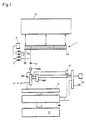
Le dispositif représenté figure 1 est utilisable dans des appareillages à ultrasons travaillant en réflexion d'impulsions, pour le contrôle non destructif des matériaux ou l'imagerie médicale.The device shown in FIG. 1 can be used in switchgear ultrasound working in pulse reflection, for non-destructive testing materials or medical imagery.
Il fait intenvenir une sonde 1 constituée par une barrette linéaire composée
d'une pluralité d'éléments émetteurs/récepteurs D1 à Dn de faible dimension
(1 mm) par exemple au nombre de 128. De ce fait, la même sonde 1 est
utilisée à l'émission et à la réception.It involves a
Chaque élément D1 à Dn est relié, d'une part, à une zone, ici une ligne L1 ... Ln
respective d'une mémoire de champ MC, par l'intermédiaire d'un
préamplificateur A et d'un convertisseur analogique/numérique CAN et, d'autre
part, à un émetteur E, par l'intermédiaire de deux diodes 2, 3 montées tête-bêche,
présentant un seuil de conduction par exemple de l'ordre d'une fraction
de volt.Each element D 1 to D n is connected, on the one hand, to a zone, here a line L 1 ... L n respectively of a field memory MC, by means of a preamplifier A and d an analog / digital converter CAN and, on the other hand, to a transmitter E, via two
Ainsi, lorsque l'émetteur E émet en délivrant une tension pouvant atteindre une
centaine de volts alternatifs, les diodes 2, 3 associées à tous les éléments
émetteurs/récepteurs D1 à D9 sont largement conductrices et se comportent
comme des courts-circuits, de sorte que tous les éléments D1 à D9 sont excités
en parallèle par l'émetteur E et produisent donc une onde plane.Thus, when the transmitter E transmits by delivering a voltage of up to a hundred alternating volts, the
Par contre, à la réception, chaque élément D1 à D9 travaille de façon indépendante et attaque le préamplificateur A auquel il se trouve relié. En effet, les signaux détectés par les éléments sont faibles (quelques dizaines de millivolts).On the other hand, on reception, each element D 1 to D 9 works independently and attacks the preamplifier A to which it is connected. Indeed, the signals detected by the elements are weak (a few tens of millivolts).
Cette disposition a en outre l'avantage de diminuer le bruit d'entrée en isolant les préamplificateurs A du circuit d'émission This arrangement also has the advantage of reducing input noise by insulating the preamplifiers A of the transmission circuit
Chaque préamplificateur A attaque ensuite un convertisseur analogique/ numérique CAN correspondant et les signaux numérisés sont stockés dans les lignes de mémoires L1 à Ln, à des adresses d'écritures fournies par une mémoire d'adressage MA elle-même adressée par un compteur CR piloté par une horloge CK. Ce compteur CR et cette horloge CK sont communs à toutes les mémoires d'adressage MA associées aux lignes de mémoires L1 à Ln.Each preamplifier A then drives a corresponding analog / digital converter CAN and the digitized signals are stored in the memory lines L 1 to L n , at write addresses supplied by an address memory MA itself addressed by a counter. CR controlled by a CK clock. This counter CR and this clock CK are common to all the address memories MA associated with the memory lines L 1 to L n .
Lors de l'écriture des lignes de mémoires L1 à Ln, les sorties des mémoires d'adressage correspondent à la valeur du compteur CR. Tout se passe donc comme si les lignes de mémoires de champ L1 à Ln étaient adressées en parallèle par le compteur CR.When writing the memory lines L 1 to L n , the outputs of the address memories correspond to the value of the counter CR. Everything therefore takes place as if the lines of field memories L 1 to L n were addressed in parallel by the counter CR.
Avantageusement, le nombre No de positions mémoires utilisées lors de l'opération d'écriture est choisi parmi les puissances de deux soit, par exemple, 512, 1024, etc..Advantageously, the number No of memory positions used during the write operation is chosen from among the powers of two, for example, 512, 1024, etc.
Si, par exemple, No est égal à 512, les positions 0 à 511 de la mémoire de
champ sont écrites.If, for example, No is equal to 512, the
Aussitôt après l'écriture, les mémoires L1 à Ln sont commutées en position lecture, par l'intermédiaire d'une bascule B commandée par le bit 10 du compteur CR.Immediately after writing, the memories L 1 to L n are switched to the read position, by means of a flip-flop B controlled by bit 10 of the counter CR.
A partir de l'adresse 512, les sorties des lignes de mémoires de champ L1 à Ln ne sont plus identiques, mais sont calculées de façon que les positions de mémoire adressées correspondent à une forme prédéterminée (hyperbole de lecture).From address 512, the outputs of the field memory lines L 1 to L n are no longer identical, but are calculated so that the addressed memory positions correspond to a predetermined shape (read hyperbola).
Ce calcul est effectué de la façon suivante à partir de l'adresse 512, le compteur CR adresse une position P'ij d'une mémoire Mi (figure 2). A chaque point P'11 à P'nm de cette mémoire Mi on fait correspondre une position P11 à Pnm de l'objet examiné O, de manière à ce que cette mémoire "image" Mi puisse être exploitée par la suite pour fournir une image de l'objet O.This calculation is carried out as follows from the address 512, the counter CR addresses a position P'ij of a memory Mi (FIG. 2). At each point P '11 to P'nm of this memory Mi is made to correspond a position P 11 to P nm of the examined object O, so that this memory "image" Mi can be operated subsequently to provide an image of the object O.
Pour chacun de ces points, P'11, P'nm, on calcule les positions occupées dans les lignes de mémoires de champ L1 à Ln par l'impulsion ultrasonore réfléchie, en tenant compte de la forme du champ émis, de la fréquence de numérisation, de la vitesse du son, de la position de l'objet par rapport à la sonde. Ainsi, pour le point Pij de l'objet qui correspond au point P'ij de la mémoire "image" Mi, les positions occupées dans la mémoire de champ MC sont disposées selon une hyperbole indiquée par les hachures.For each of these points P 11, P nm, we calculate the positions occupied in the field memories lines L 1 to L n by the reflected ultrasonic pulse, taking into account the shape of the emitted field, scanning frequency, speed of sound, position of the object relative to the probe. Thus, for the point Pij of the object which corresponds to the point P'ij of the "image" memory Mi, the positions occupied in the field memory MC are arranged according to a hyperbola indicated by the hatching.
Si la sonde 1 est en contact direct avec l'objet, la numérisation peut
commencer en même temps que l'émission. Si l'on travaille avec un relais
acoustique, le début de la numérisation peut être différé d'un temps égal au
parcours aller-retour dans le relais.If
Les valeurs lues dans les différentes mémoires (par exemple les valeurs contenues dans les cellules des lignes de mémoires situées sur l'hyperbole H relative au point Pij) sont additionnées dans un circuit additionneur S et envoyées à la position sélectionnée de la mémoire Mi (par exemple la position P'ij).The values read in the various memories (for example the values contained in the cells of the memory lines located on the hyperbola H relative to point Pij) are added in an adder circuit S and sent to the selected position of the memory Mi (for example the position P'ij).
Comme précédemment mentionné, les informations contenues dans la mémoire Mi peuvent être exploitées de différentes manières.As previously mentioned, the information in the Mi memory can be used in different ways.
Elles peuvent servir à former une image sur un écran de visualisation V de type classique.They can be used to form an image on a display screen V of classic type.
Ces informations peuvent être également traitées, par exemple, par des circuits logiques permettant d'identifier et d'enregistrer la nature des défauts détectés dans le cas d'un contrôle non destructif This information can also be processed, for example, by circuits logic to identify and record the nature of detected faults in the case of non-destructive testing
Les mémoires d'adressage MA peuvent être des mémoires mortes (ROM, PROM, EPROM) programmées une fois pour toutes. Toutefois, il est préférable. tant en ce qui concerne la vitesse que la souplesse d'exploitation. d'utiliser des mémoires reprogrammables une fois en place, par exemple des RAM.The address memories MA can be read only memories (ROM, PROM, EPROM) programmed once and for all. However, it is preferable. both in terms of speed and flexibility of operation. to use reprogrammable memories once in place, for example RAM.
La programmation peut se faire alors au moment de la mise en route. Le calcul préalable peut être effectué par un mini-ordinateur en fonction des conditions d'examen et du modèle de sonde utilisé. Les données peuvent aussi être précalculées et stockées sur disques ou sur PROM. Les résultats sont ensuite transférés séquentiellement dans la mémoire MA par un procédé classique. Ce transfert peut être très rapide (quelques secondes).Programming can then be done at the time of start-up. The calculation preliminary can be done by a mini-computer depending on the conditions and the model of probe used. Data can also be precomputed and stored on discs or on PROM. The results are then transferred sequentially to the memory MA by a conventional method. This transfer can be very fast (a few seconds).
Un mode de calcul des adresses dans les mémoires d'adressage MA sera décrit ci-après en regard de la figure 2.A method of calculating the addresses in the address memories MA will be described below with reference to Figure 2.
Soit le point Pij situé à une distance d de la sonde à l'aplomb de l'élément de détection Di, on fait correspondre à ce point Pij une position P'ij de la mémoire "image" Mi, donc une adresse fournie par le compteur CR.Let the point Pij located at a distance d from the probe plumb with the element of detection Di, we make this point Pij correspond to a position P'ij of the "image" memory Mi, therefore an address supplied by the counter CR.
Soit x la distance séparant l'élément D1 de la sonde 1 et l'élément Di à l'aplomb
du point Pij, et c la vitesse du son dans le milieu objet.Let x be the distance separating element D 1 from
Si l'on suppose que l'onde émise par la sonde 1 est plane et se propage
perpendiculairement à la surface de la sonde 1, le temps t(x) mis par une
impulsion pour parvenir à un organe de détection par exemple D3 après
réflexion sur le point Pij est égal à d/c (temps mis par l'onde émise pour
atteindre Pij) + racine carrée de (x2 + d2)/c :
Si la fréquence d'écriture est désignée par f et si l'écriture démarre en même temps que l'émission, le signal réfléchi va être stocké dans la cellule de la mémoire de champ MC située à l'abscisse x, à la position f. t(x).If the writing frequency is designated by f and if writing starts at the same time time that the emission, the reflected signal will be stored in the cell of the MC field memory located on the abscissa x, at position f. t (x).
C'est la valeur f. t(x) qui va être introduite dans la mémoire MA pour être utilisée lors de l'opération de lecture.It is the value f. t (x) which will be introduced into the memory MA to be used during the read operation.
Si l'onde ne se propage pas perpendiculairement à la sonde (sondage sous
incidence inclinée) ou si l'onde n'est pas plane (onde circulaire dans le cas d'un
sondage sectoriel) le calcul se fait de façon très similaire, seul change le temps
mis par l'onde pour atteindre un point Pij. Ce temps ne dépend plus seulement
de d mais aussi de la position latérale du point Pij par rapport à la sonde 1. Si
l'onde est inclinée, le temps varie linéairement en fonction de la position
latérale Xp, le temps mis par l'onde émise pour atteindre le point Pij étant égal
à (d . cos () - Xp . sin )/C, étant l'angle du faisceau émis par rapport à la
normale à la sonde 1.If the wave does not propagate perpendicular to the probe (probing under
inclined incidence) or if the wave is not plane (circular wave in the case of a
sector survey) the calculation is done in a very similar way, only changes the time
put by the wave to reach a point Pij. This time no longer depends only
of d but also of the lateral position of the point Pij relative to the
Dans le cas où les ondes engendrées par la sonde 1 sont entretenues ou semi-entretenues
et où ces ondes ont la forme d'un train d'ondes d'une durée
suffisante pour couvrir tout l'objet, chaque point donne naissance à une onde
réfléchie de durée telle qu'elle va être mémorisée dans presque toutes les
positions des lignes de mémoires MC. et les informations correspondant à des
points différents vont se superposer.In the case where the waves generated by the
On peut considérer alors qu'une "tranche" de ces mémoires contiendra toutes les informations correspondant à l'objet, à partir du moment où cette tranche aura une "épaisseur" suffisante pour contenir la plus grande des hyperboles. We can then consider that a "slice" of these memories will contain all the information corresponding to the object, from the moment when this section will have a "thickness" sufficient to contain the largest of the hyperbolas.
La lecture de cette unique tranche sera donc en principe suffisante pour recréer l'image de l'objet.Reading this single section will therefore in principle be sufficient to recreate the image of the object.
Cette lecture pourra se faire en modifiant progressivement la forme des hyperboles de lecture, ou en "mettant au point" sur une zone située à une distance donnée.This reading can be done by gradually changing the shape of the reading hyperbolas, or by "focusing" on an area located given distance.
La numérisation du signal devra alors se faire sur un nombre de niveaux plus élevés, pour permettre une bonne discrimination des différentes informations.The digitization of the signal must then be done on a number of more levels high, to allow good discrimination of different information.
On peut aussi envisager, pour simplifier l'électronique, d'adresser séquentiellement les mémoires MC lors de l'écriture, la relecture se faisant toujours en parallèle (un seul préamplificateur et un seul convertisseur analogique/numérique sont alors nécessaires).We can also consider, to simplify the electronics, to address sequentially the MC memories during the writing, the re-reading being done always in parallel (a single preamplifier and a single converter analog / digital are necessary).
La vitesse d'acquisition est alors notablement diminuée, mais la résolution reste élevée. Cette solution peut être intéressante lorsque la recherche de la vitesse n'est pas une priorité. Des solutions mixtes peuvent aussi être envisagées : écriture parallèle sur des groupes de mémoires, ces groupes étant adressés séquentiellement.The acquisition speed is then significantly reduced, but the resolution stays high. This solution can be interesting when looking for the speed is not a priority. Mixed solutions can also be envisaged: parallel writing on memory groups, these groups being addressed sequentially.
Dans l'exemple précédemment décrit, le signal ultrasonore est mémorisé avant détection, donc au niveau haute fréquence. La fréquence d'échantillonnage doit être au moins égale à trois fois la fréquence ultrasonore soit, par exemple, de 10 MHz pour une onde ultrasonore de 3 MHz.In the example described above, the ultrasonic signal is memorized before detection, therefore at high frequency level. The sampling frequency must be at least three times the ultrasonic frequency, for example, 10 MHz for a 3 MHz ultrasonic wave.
Ainsi. dans le cas où l'on désire sonder une profondeur de 10 cm dans l'acier, le temps de parcours aller-retour maximum est égal à environ 60 microsecondes, soit 600 points échantillonnés sur chaque ligne.So. if you want to probe a depth of 10 cm in the steel, the maximum round trip time is approximately 60 microseconds, or 600 points sampled on each line.
Pour une image de 100 lignes, il faudra donc calculer 600 x 100 = 60.000 points. For an image of 100 lines, it will therefore be necessary to calculate 600 x 100 = 60,000 points.
Le calcul se réduit ici à une simple lecture de mémoire suivi d'une addition.The calculation is reduced here to a simple reading of memory followed by an addition.
Cette opération peut être réalisée, avec des circuits modernes, en 1/100 de microseconde. La totalité de l'image sera donc calculée en 60.000/100 = 600 microsecondes.This operation can be carried out, with modern circuits, in 1/100 of microsecond. The entire image will therefore be calculated in 60,000 / 100 = 600 microseconds.
La mémorisation du champ aura duré 60 microsecondes, et le temps total d'acquisition d'une image sera donc égal à 660 microsecondes, la cadence image pourra être supérieure à 1000 Hz.The memorization of the field will have lasted 60 microseconds, and the total time acquisition of an image will therefore be equal to 660 microseconds, the rate image may be greater than 1000 Hz.
Si cette cadence s'avère insuffisante, elle peut être augmentée de plusieurs
manières :
Il est à noter que l'onde ultrasonore a souvent la forme d'une impulsion brève comprenant plusieurs alternances. Il peut alors être intéressant d'utiliser plusieurs hyperboles de lecture interceptant ces alternances. Si l'impulsion est courte et ne comporte qu'une alternance complète, une hyperbole pourra être utilisée pour relire l'alternance positive et à une distance correspondant à une demi période pour relire la négative. Si Pp et Pm sont les valeurs obtenues après ces relectures, la valeur P = Pp - Pm sera enregistrée. Cette solution peut améliorer le rapport signal/bruit et la résolution du système. Les deux lectures peuvent se faire successivement, au détriment de la vitesse, ou en parallèle, en utilisant deux groupes de mémoiresIt should be noted that the ultrasonic wave often has the form of a short pulse. comprising several alternations. It can then be interesting to use several reading hyperbolas intercepting these alternations. If the impulse is short and has only full alternation, a hyperbola can be used to re-read the positive alternation and at a distance corresponding to a half period to re-read the negative. If Pp and Pm are the values obtained after these readings, the value P = Pp - Pm will be saved. This solution can improve signal-to-noise ratio and system resolution. The two readings can be done successively, at the expense of speed, or in parallel, using two memory groups
Le procédé selon l'invention présente de nombreux avantages vis-à-vis des procédés séquentiels. The method according to the invention has numerous advantages over sequential processes.
Vitesse : Une surface importante est explorée à chaque tir, par exemple 100 x 5 mm, au lieu de 3 x 3 mm dans le procédé séquentiel. Speed : A large area is explored with each shot, for example 100 x 5 mm, instead of 3 x 3 mm in the sequential process.
La vitesse d'examen peut être multipliée par 50 ou 100 par rapport au procédé séquentiel, ce qui est considérable.The examination speed can be multiplied by 50 or 100 compared to the process sequential, which is considerable.
La rapidité du système ouvre la voie à de nombreuses applications, par exemple l'imagerie tridimensionnelle et l'imagerie Doppler.The speed of the system opens the way to many applications, for example three-dimensional imagery and Doppler imagery.
L'imagerie tridimensionnelle peut s'obtenir aisément si l'on utilise une sonde matricielle, mais l'électronique est très lourde, car le nombre d'éléments d'une sonde matricielle classique est élevé. Cependant, il est possible de réduire sensiblement le nombre d'éléments en utilisant une répartition aléatoire de ces derniers sur la surface de la sonde, ce qui autorise un espacement plus grand des éléments sans que les lobes parasites deviennent trop importants. Avec une sonde linéaire, une série de plans peut être rapidement enregistrée en déplaçant le plan de coupe entre chaque tir. A une cadence de 100 Hz. 100 plans de coupe peuvent être mémorisés en 1/10 seconde. Les mémoires peuvent être ensuite exploitées pour obtenir une vue tridimensionnelle, ou une vue en coupe dans un plan quelconque.Three-dimensional imagery can be easily obtained using a probe matrix, but the electronics are very heavy, because the number of elements of a classic array probe is high. However, it is possible to reduce substantially the number of elements using a random distribution of these last on the surface of the probe, which allows a greater spacing elements without the parasitic lobes becoming too large. With a linear probe, a series of planes can be quickly recorded by moving the cutting plane between each shot. At a rate of 100 Hz. 100 shots of cuts can be memorized in 1/10 second. Memories can be then used to obtain a three-dimensional view, or a sectional view in any plane.
En ce qui concerne l'imagerie Doppler, l'application à l'imagerie Doppler résulte du fait que des images successives peuvent être comparées. Le signal haute fréquence étant mémorisé, des différences très faibles entre deux images peuvent être décelées (par soustraction, par exemple) et mises en évidence.With regard to Doppler imaging, the application to Doppler imaging results from the fact that successive images can be compared. The signal high frequency being memorized, very small differences between two images can be detected (by subtraction, for example) and highlighted.
résolution : Le système travaille avec une très grande ouverture numérique. Pratiquement, la résolution spatiale n'est limitée que par la plus grande des deux valeurs : longueur d'onde - dimension d'un élément. Ainsi, dans l'exemple cité, la plus grande de ces deux valeurs est la longueur d'onde, soit 2 mm. Avec une fréquence de 10 MHz, la plus grande des deux valeurs serait la dimension d'un élément, soit ici 1 mm. resolution : The system works with a very large numerical aperture. In practice, the spatial resolution is limited only by the larger of the two values: wavelength - dimension of an element. Thus, in the example cited, the greater of these two values is the wavelength, ie 2 mm. With a frequency of 10 MHz, the larger of the two values would be the dimension of an element, here 1 mm.
Reproductibilité : La sensibilité du système varie très peu en fonction de la position d'un obstacle sous la sonde, puis le champ est émis sous forme d'une onde plane. De plus, les variations de sensibilité en fonction de la position peuvent être calculées, et donc corrigées, puisque l'on connaít la position exacte de chaque obstacle par rapport à la sonde. Reproducibility : The sensitivity of the system varies very little depending on the position of an obstacle under the probe, then the field is emitted in the form of a plane wave. In addition, variations in sensitivity depending on the position can be calculated, and therefore corrected, since we know the exact position of each obstacle relative to the probe.
Le système peut fonctionner avec des fronts d'ondes d'émission de forme quelconque (plans, plans inclinés, cylindriques). Il suffit de calculer dans chaque cas la forme des hyperboles de lecture en fonction de leur position.The system can work with shape emission wave fronts any (planes, inclined planes, cylindrical). Just calculate in each case forms the reading hyperbolas according to their position.
Claims (15)
- A method for the processing of signals representative of reflected transmitted waves by an environment (O), with a view to exploring and analyzing the structure of said environment (O), said method comprising the following steps :characterised in thatthe emission of one incident wave in said structure,the reception of the reflected or transmitted waves by the structure encountered by the incident wave inside the environment (O), by a plurality of detection elements (D1 to Dn) independent of one another,the storage after digitalization of the signals supplied by the detection elements, in a field memory (MC) comprising a respective line (L1 to Ln) by detection element (D1 to Dn), andthe reconstitution and/or analysis of the structure of the environment (O) from the read information in the field memory (MC), in which are computed for each point (Pij) of the environment (O), the positions of the field memory containing the detected signals by the detection elements (D1 to Dn) corresponding to the reflected or transmitted waves by this point (Pij), said positions being computed by the way of an addressing law, the parameters of which depend on the position of this point with regard to the detection means, and in which for each point (Pij), the lines (L1 to Ln) of the field memory (MC) are read to the respective positions computed preliminary for this point (Pij), and stored in addressing memories (MA) respectively associated to said lines (L1 to Ln) of the field memory, and a computation is applied to the read values for this point to obtain a result (Vp) representative of the importance of the reflected or transmitted wave originating from this point, during said computation, all the lines (L1 to Ln) of the memory field (MC) being read in parallel for each point (Pij) to the indicated positions for this point respectively by the associated addressing memories (MA), the computing of the result (Vp) being then applied to all the read values in the field memory (MC), said result being then processed or memorized in a specific memory,the incident wave comprises at least one complete alternance,the sampling frequency used for the digitalization of the detection signals is equal to at least three times the frequency of the incident wave,during said reconstitution phase, the reading in the field memory of the values corresponding to the positive and negative alternances is executed,the first values are compasated by the second values in order to record in said specific memory a compasated value presenting an improved ratio signal/sound.
- Method according to claim 1,
the result (Vp) for each point (Pij) is memorized in an image memory (Mi) comprising a plurality of positions (P1' to Pn') corresponding respectively to the points (Pij). - The method according claim 1 or 2,
characterised in that said addressing law is a hyperbolic law, and the computation applied to the values read in the field memory (MC) is an addition. - The method according one of the preceding claims,
characterised in that plural read addressing laws are associated with each point (P1 to Pn) of the image memory. - The method according one of the preceding claims,
characterised in that said incident waves are transmitted in the form of pulses. - The method according one of the claims 1 to 3,
characterised in that the incident waves are transmitted in the form of wave trains or of a continuous transmission, the hyperbolic law then being chosen so as to highlight the reflecting points situated at a predetermined distance. - The method according one of the preceding claims,
characterised in that the transmission of the incident waves and reception of the waves reflected are performed by the same means. - The method according one of the claims 1 to 6,
characterised in that the transmission of the incident waves and reception of the waves reflected or transmitted are performed by separate means. - The method according one of the preceding claims,
characterised in that the incident wave fronts are plane. - The method according claim 1,
characterised in that the incident waves are comprised of directive and/or focalized beams that do not overlap, these beams being displaced in the course of successive transmissions in order to cover the entire structure explored. - The method according claim 1,
characterised in that said incident waves are generated by means of a linear network of independent transmission/reception devices. - The method according claim 1,
characterised in that the incident waves are generated by means of transmission/reception devices arranged according to a matrix configuration. - The method according claim 1,
characterised in that the incident waves are generated by means of transmission/reception devices arranged randomly. - A device for implementing the method according claim 1,
characterised in that it comprises a probe (1) comprised of a plurality of transmitter/receiver elements (D1 to Dn) each connected, on the one hand, to a transmitter (E), via two conduction threshold diodes (2, 3) mounted head-to-foot, and, on the other hand, to an analog-to-digital converter (CAN), of which the output is connected to the write input of a respective line (L1 to Ln) of a field memory (MC), of which the reading is controlled by an addressing memory (MA) driven by a clock (CK) via a counter (CR), the read output of the lines (L1 to Ln) of the field memories (MC) being connected to an adder (S) of which the output is connected to the write input of an image memory (Mi) driven by said counter (CR). - The device according claim 14,
characterised in that said image memory (Mi) is operated by a display device.
Applications Claiming Priority (2)
| Application Number | Priority Date | Filing Date | Title |
|---|---|---|---|
| FR9610325A FR2752461B1 (en) | 1996-08-14 | 1996-08-14 | METHOD AND DEVICE FOR THE PROCESSING OF REPRESENTATIVE SIGNALS OF WAVES REFLECTED OR TRANSMITTED BY A VOLUME STRUCTURE WITH A VIEW TO PERFORMING AN EXPLORATION AND ANALYSIS OF THE STRUCTURE |
| FR9610325 | 1996-08-14 |
Publications (2)
| Publication Number | Publication Date |
|---|---|
| EP0825453A1 EP0825453A1 (en) | 1998-02-25 |
| EP0825453B1 true EP0825453B1 (en) | 2001-08-01 |
Family
ID=9495138
Family Applications (1)
| Application Number | Title | Priority Date | Filing Date |
|---|---|---|---|
| EP97401409A Expired - Lifetime EP0825453B1 (en) | 1996-08-14 | 1997-06-19 | Method and apparatus for processing signals representative of waves which have been reflected by or transmitted through a volume structure, in order to enable exploration and analysis of said structure |
Country Status (11)
| Country | Link |
|---|---|
| US (1) | US6023660A (en) |
| EP (1) | EP0825453B1 (en) |
| JP (1) | JPH10123109A (en) |
| CN (1) | CN1187612C (en) |
| AT (1) | ATE203833T1 (en) |
| CA (1) | CA2211419C (en) |
| DE (1) | DE69705900T2 (en) |
| ES (1) | ES2162213T3 (en) |
| FR (1) | FR2752461B1 (en) |
| MY (1) | MY125709A (en) |
| RU (1) | RU2178880C2 (en) |
Cited By (1)
| Publication number | Priority date | Publication date | Assignee | Title |
|---|---|---|---|---|
| US10025272B2 (en) | 2013-01-25 | 2018-07-17 | General Electric Company | Ultrasonic holography imaging system and method |
Families Citing this family (8)
| Publication number | Priority date | Publication date | Assignee | Title |
|---|---|---|---|---|
| US6685645B1 (en) * | 2001-10-20 | 2004-02-03 | Zonare Medical Systems, Inc. | Broad-beam imaging |
| FR2855271B1 (en) * | 2003-05-22 | 2006-01-21 | Jacques Dory | PROCESS FOR EXPLORATION AND ANALYSIS OF A VOLUME STRUCTURE |
| DE10334902B3 (en) * | 2003-07-29 | 2004-12-09 | Nutronik Gmbh | Signal processing for non-destructive object testing involves storing digitized reflected ultrasonic signals and phase-locked addition of stored amplitude values with equal transition times |
| US20070112528A1 (en) * | 2005-10-25 | 2007-05-17 | Scott Farrell | Leak detection system and method |
| JP4984519B2 (en) * | 2005-12-19 | 2012-07-25 | Jfeスチール株式会社 | Method and apparatus for inspecting cross section of metal material by ultrasonic wave |
| US9213086B2 (en) * | 2007-05-14 | 2015-12-15 | Fujifilm Sonosite, Inc. | Computed volume sonography |
| US8235902B2 (en) * | 2007-09-11 | 2012-08-07 | Focus Surgery, Inc. | System and method for tissue change monitoring during HIFU treatment |
| US9639056B2 (en) * | 2013-09-17 | 2017-05-02 | General Electric Company | Acoustical holography with multi-level square wave excitation signals |
Family Cites Families (14)
| Publication number | Priority date | Publication date | Assignee | Title |
|---|---|---|---|---|
| US4165649A (en) * | 1975-02-13 | 1979-08-28 | Southwest Research Institute | Apparatus and method for ultrasonic inspection of highly attenuative materials |
| JPS57179745A (en) * | 1981-04-30 | 1982-11-05 | Fujitsu Ltd | Method and device for measuring material property by ultrasonic wave |
| JPS60116345A (en) * | 1983-11-30 | 1985-06-22 | 富士通株式会社 | Ultrasonic diagnostic apparatus |
| JPH0619471B2 (en) * | 1984-03-30 | 1994-03-16 | 株式会社日立製作所 | Method and apparatus for identifying underground objects |
| JPS6111658A (en) * | 1984-06-28 | 1986-01-20 | Terumo Corp | Method and device for measuring ultrasonic wave |
| US4787393A (en) * | 1985-11-20 | 1988-11-29 | Matsushita Electric Industrial Co., Ltd. | Ultrasonic tomographic with alternate image scaling |
| JPS641958A (en) * | 1987-06-25 | 1989-01-06 | Mitsubishi Electric Corp | Object section visualizer |
| JPH02263180A (en) * | 1989-04-03 | 1990-10-25 | Toshiba Corp | Aperture synthetic processor |
| JPH0640096B2 (en) * | 1989-05-22 | 1994-05-25 | 工業技術院長 | Method and apparatus for measuring spatial distribution of minute scatterers |
| DE69131798T2 (en) * | 1990-06-12 | 2000-05-11 | Univ Florida | METHOD FOR AUTOMATICALLY QUANTIZING DIGITALIZED IMAGE DATA |
| JP2757268B2 (en) * | 1990-11-16 | 1998-05-25 | 日本電信電話株式会社 | Invisible object search method |
| JPH04188058A (en) * | 1990-11-21 | 1992-07-06 | Olympus Optical Co Ltd | Ultrasonic-wave flaw detecting apparatus |
| JP2785636B2 (en) * | 1993-02-25 | 1998-08-13 | 株式会社エス.エス.ビー | Biological tissue multidimensional visualization device |
| US5347495A (en) * | 1993-04-30 | 1994-09-13 | Milltronics Ltd. | Matching transformer for ultrasonic transducer |
-
1996
- 1996-08-14 FR FR9610325A patent/FR2752461B1/en not_active Expired - Fee Related
-
1997
- 1997-06-19 DE DE69705900T patent/DE69705900T2/en not_active Expired - Fee Related
- 1997-06-19 ES ES97401409T patent/ES2162213T3/en not_active Expired - Lifetime
- 1997-06-19 AT AT97401409T patent/ATE203833T1/en not_active IP Right Cessation
- 1997-06-19 EP EP97401409A patent/EP0825453B1/en not_active Expired - Lifetime
- 1997-06-26 MY MYPI97002887A patent/MY125709A/en unknown
- 1997-07-15 CA CA002211419A patent/CA2211419C/en not_active Expired - Fee Related
- 1997-08-08 RU RU97114148/09A patent/RU2178880C2/en not_active IP Right Cessation
- 1997-08-13 CN CNB97117640XA patent/CN1187612C/en not_active Expired - Fee Related
- 1997-08-13 US US08/910,878 patent/US6023660A/en not_active Expired - Fee Related
- 1997-08-14 JP JP9219578A patent/JPH10123109A/en active Pending
Cited By (1)
| Publication number | Priority date | Publication date | Assignee | Title |
|---|---|---|---|---|
| US10025272B2 (en) | 2013-01-25 | 2018-07-17 | General Electric Company | Ultrasonic holography imaging system and method |
Also Published As
| Publication number | Publication date |
|---|---|
| ES2162213T3 (en) | 2001-12-16 |
| FR2752461B1 (en) | 1998-11-06 |
| DE69705900T2 (en) | 2002-04-04 |
| RU2178880C2 (en) | 2002-01-27 |
| MY125709A (en) | 2006-08-30 |
| CA2211419C (en) | 2009-02-10 |
| CN1176386A (en) | 1998-03-18 |
| FR2752461A1 (en) | 1998-02-20 |
| JPH10123109A (en) | 1998-05-15 |
| ATE203833T1 (en) | 2001-08-15 |
| CA2211419A1 (en) | 1998-02-14 |
| EP0825453A1 (en) | 1998-02-25 |
| DE69705900D1 (en) | 2001-09-06 |
| US6023660A (en) | 2000-02-08 |
| CN1187612C (en) | 2005-02-02 |
Similar Documents
| Publication | Publication Date | Title |
|---|---|---|
| EP0591061B1 (en) | Method and device for acoustic examination with time reversal | |
| EP0872742B1 (en) | Method and system for processing signals representing reflected waves, transmitted or diffracted by a volumetric structure, for the purpose of effecting an investigation and an analysis of this structure | |
| EP0541434B1 (en) | Method and apparatus for the ultrasonic testing of workpieces | |
| US7089796B2 (en) | Time-reversed photoacoustic system and uses thereof | |
| EP0383650A1 (en) | Process and apparatus for locating and focusing waves | |
| EP0709673A1 (en) | Apparatus for non-destructive testing of hollow tubular articles with ultrasound | |
| FR2851662A1 (en) | Medium e.g. linear probe, discontinuity detecting method for e.g. portable medical apparatus, involves applying coherence criteria to selected maxima for regrouping maxima to same discontinuity, where maxima has value higher than threshold | |
| EP0124442B1 (en) | Method and device for acoustic holographyx using an altrasonic beam limited in space | |
| EP0543445A1 (en) | Examination device for media by means of ultrasonic echography | |
| EP0825453B1 (en) | Method and apparatus for processing signals representative of waves which have been reflected by or transmitted through a volume structure, in order to enable exploration and analysis of said structure | |
| EP0718639A1 (en) | Process and device for detecting objects distributed in a field | |
| EP0718638B1 (en) | Method of detection of objects located in a ground area or of determination of the propagation characteristics of an acoustic wave in the ground, and system to carry out these methods | |
| FR2558956A1 (en) | METHOD AND DEVICE FOR SEARCHING AND CHARACTERIZING DEFECTS OF A SUBSTANDED KNOWN METAL STRUCTURE | |
| EP0196714B1 (en) | Method and device for the ultrasonic, echographic investigation of media | |
| EP4083659B1 (en) | Device and method for processing the signal from a set of ultrasonic transducers | |
| EP1629303A1 (en) | Method for scanning and analysing a three-dimensional structure | |
| EP0040566A1 (en) | Dynamically-focused sector-scan imaging unit | |
| FR2908516A1 (en) | Ultrasonic waves transmitting and/or receiving method for controlling e.g. preconstraint cable, involves using probe for reception of waves, where probe has characteristics permitting to create reproduced distribution for emission | |
| WO1997004333A1 (en) | Imaging method and device with parallel processing of data | |
| FR2507324A1 (en) | ACOUSTIC SOURCE LOCATION METHOD, DEVICE IMPLEMENTING SUCH A METHOD, AND APPARATUS FOR INPUTTING GRAPHIC DATA USING THE SAME | |
| FR2908517A1 (en) | Elastic ultrasonic wave transmitting and receiving method for e.g. controlling post-constraint cable, involves utilizing probes for reception of waves, where probes are selectively sensitive at mode chosen at frequency, during reception |
Legal Events
| Date | Code | Title | Description |
|---|---|---|---|
| PUAI | Public reference made under article 153(3) epc to a published international application that has entered the european phase |
Free format text: ORIGINAL CODE: 0009012 |
|
| 17P | Request for examination filed |
Effective date: 19970703 |
|
| AK | Designated contracting states |
Kind code of ref document: A1 Designated state(s): AT DE ES GB IT NL SE |
|
| AKX | Designation fees paid |
Free format text: AT DE ES GB IT NL SE |
|
| RBV | Designated contracting states (corrected) |
Designated state(s): AT DE ES GB IT NL SE |
|
| 17Q | First examination report despatched |
Effective date: 19991201 |
|
| GRAG | Despatch of communication of intention to grant |
Free format text: ORIGINAL CODE: EPIDOS AGRA |
|
| GRAG | Despatch of communication of intention to grant |
Free format text: ORIGINAL CODE: EPIDOS AGRA |
|
| GRAH | Despatch of communication of intention to grant a patent |
Free format text: ORIGINAL CODE: EPIDOS IGRA |
|
| GRAH | Despatch of communication of intention to grant a patent |
Free format text: ORIGINAL CODE: EPIDOS IGRA |
|
| GRAA | (expected) grant |
Free format text: ORIGINAL CODE: 0009210 |
|
| AK | Designated contracting states |
Kind code of ref document: B1 Designated state(s): AT DE ES GB IT NL SE |
|
| PG25 | Lapsed in a contracting state [announced via postgrant information from national office to epo] |
Ref country code: AT Free format text: LAPSE BECAUSE OF FAILURE TO SUBMIT A TRANSLATION OF THE DESCRIPTION OR TO PAY THE FEE WITHIN THE PRESCRIBED TIME-LIMIT Effective date: 20010801 |
|
| REF | Corresponds to: |
Ref document number: 203833 Country of ref document: AT Date of ref document: 20010815 Kind code of ref document: T |
|
| GBT | Gb: translation of ep patent filed (gb section 77(6)(a)/1977) |
Effective date: 20010801 |
|
| REF | Corresponds to: |
Ref document number: 69705900 Country of ref document: DE Date of ref document: 20010906 |
|
| ITF | It: translation for a ep patent filed |
Owner name: ING. A. GIAMBROCONO & C. S.R.L. |
|
| PG25 | Lapsed in a contracting state [announced via postgrant information from national office to epo] |
Ref country code: SE Free format text: LAPSE BECAUSE OF FAILURE TO SUBMIT A TRANSLATION OF THE DESCRIPTION OR TO PAY THE FEE WITHIN THE PRESCRIBED TIME-LIMIT Effective date: 20011101 |
|
| REG | Reference to a national code |
Ref country code: ES Ref legal event code: FG2A Ref document number: 2162213 Country of ref document: ES Kind code of ref document: T3 |
|
| REG | Reference to a national code |
Ref country code: GB Ref legal event code: IF02 |
|
| PLBE | No opposition filed within time limit |
Free format text: ORIGINAL CODE: 0009261 |
|
| STAA | Information on the status of an ep patent application or granted ep patent |
Free format text: STATUS: NO OPPOSITION FILED WITHIN TIME LIMIT |
|
| 26N | No opposition filed | ||
| PGFP | Annual fee paid to national office [announced via postgrant information from national office to epo] |
Ref country code: ES Payment date: 20080603 Year of fee payment: 12 |
|
| PGFP | Annual fee paid to national office [announced via postgrant information from national office to epo] |
Ref country code: IT Payment date: 20080527 Year of fee payment: 12 |
|
| PGFP | Annual fee paid to national office [announced via postgrant information from national office to epo] |
Ref country code: NL Payment date: 20080626 Year of fee payment: 12 Ref country code: DE Payment date: 20080821 Year of fee payment: 12 |
|
| PGFP | Annual fee paid to national office [announced via postgrant information from national office to epo] |
Ref country code: GB Payment date: 20080609 Year of fee payment: 12 |
|
| GBPC | Gb: european patent ceased through non-payment of renewal fee |
Effective date: 20090619 |
|
| NLV4 | Nl: lapsed or anulled due to non-payment of the annual fee |
Effective date: 20100101 |
|
| PG25 | Lapsed in a contracting state [announced via postgrant information from national office to epo] |
Ref country code: GB Free format text: LAPSE BECAUSE OF NON-PAYMENT OF DUE FEES Effective date: 20090619 |
|
| PG25 | Lapsed in a contracting state [announced via postgrant information from national office to epo] |
Ref country code: DE Free format text: LAPSE BECAUSE OF NON-PAYMENT OF DUE FEES Effective date: 20100101 |
|
| PG25 | Lapsed in a contracting state [announced via postgrant information from national office to epo] |
Ref country code: NL Free format text: LAPSE BECAUSE OF NON-PAYMENT OF DUE FEES Effective date: 20100101 |
|
| REG | Reference to a national code |
Ref country code: ES Ref legal event code: FD2A Effective date: 20090620 |
|
| PG25 | Lapsed in a contracting state [announced via postgrant information from national office to epo] |
Ref country code: ES Free format text: LAPSE BECAUSE OF NON-PAYMENT OF DUE FEES Effective date: 20090620 |
|
| PG25 | Lapsed in a contracting state [announced via postgrant information from national office to epo] |
Ref country code: IT Free format text: LAPSE BECAUSE OF NON-PAYMENT OF DUE FEES Effective date: 20090619 |