EP0591061B1 - Method and device for acoustic examination with time reversal - Google Patents
Method and device for acoustic examination with time reversal Download PDFInfo
- Publication number
- EP0591061B1 EP0591061B1 EP93402409A EP93402409A EP0591061B1 EP 0591061 B1 EP0591061 B1 EP 0591061B1 EP 93402409 A EP93402409 A EP 93402409A EP 93402409 A EP93402409 A EP 93402409A EP 0591061 B1 EP0591061 B1 EP 0591061B1
- Authority
- EP
- European Patent Office
- Prior art keywords
- signals
- transducers
- time
- maxima
- medium
- Prior art date
- Legal status (The legal status is an assumption and is not a legal conclusion. Google has not performed a legal analysis and makes no representation as to the accuracy of the status listed.)
- Expired - Lifetime
Links
- 238000000034 method Methods 0.000 title claims description 37
- 238000002604 ultrasonography Methods 0.000 claims description 16
- 230000001934 delay Effects 0.000 claims description 14
- 230000005540 biological transmission Effects 0.000 claims description 13
- 230000015654 memory Effects 0.000 claims description 13
- 238000005286 illumination Methods 0.000 claims description 7
- 238000005259 measurement Methods 0.000 claims description 7
- 238000004364 calculation method Methods 0.000 claims description 6
- 238000002592 echocardiography Methods 0.000 claims description 5
- 230000003321 amplification Effects 0.000 claims description 3
- 230000000295 complement effect Effects 0.000 claims description 3
- 238000003199 nucleic acid amplification method Methods 0.000 claims description 3
- 238000006243 chemical reaction Methods 0.000 claims description 2
- 230000001066 destructive effect Effects 0.000 claims description 2
- 238000007689 inspection Methods 0.000 claims 1
- 230000000875 corresponding effect Effects 0.000 description 12
- 239000011159 matrix material Substances 0.000 description 12
- 230000008569 process Effects 0.000 description 9
- 238000010586 diagram Methods 0.000 description 6
- 230000002123 temporal effect Effects 0.000 description 6
- 239000002131 composite material Substances 0.000 description 3
- 238000001514 detection method Methods 0.000 description 3
- 210000001061 forehead Anatomy 0.000 description 3
- 230000004807 localization Effects 0.000 description 3
- 239000000463 material Substances 0.000 description 3
- 239000007787 solid Substances 0.000 description 3
- 238000010521 absorption reaction Methods 0.000 description 2
- 230000004913 activation Effects 0.000 description 2
- 230000015572 biosynthetic process Effects 0.000 description 2
- 230000001427 coherent effect Effects 0.000 description 2
- 230000000694 effects Effects 0.000 description 2
- 230000005284 excitation Effects 0.000 description 2
- 230000002349 favourable effect Effects 0.000 description 2
- 230000006870 function Effects 0.000 description 2
- 230000000750 progressive effect Effects 0.000 description 2
- 230000004044 response Effects 0.000 description 2
- 241001415961 Gaviidae Species 0.000 description 1
- 229910000831 Steel Inorganic materials 0.000 description 1
- 229910001069 Ti alloy Inorganic materials 0.000 description 1
- 238000013459 approach Methods 0.000 description 1
- 239000011324 bead Substances 0.000 description 1
- 230000009286 beneficial effect Effects 0.000 description 1
- 230000008901 benefit Effects 0.000 description 1
- 239000000919 ceramic Substances 0.000 description 1
- 201000001883 cholelithiasis Diseases 0.000 description 1
- 238000007796 conventional method Methods 0.000 description 1
- 230000002596 correlated effect Effects 0.000 description 1
- 238000005314 correlation function Methods 0.000 description 1
- 230000006378 damage Effects 0.000 description 1
- 230000007547 defect Effects 0.000 description 1
- 230000003111 delayed effect Effects 0.000 description 1
- 230000001627 detrimental effect Effects 0.000 description 1
- 238000005516 engineering process Methods 0.000 description 1
- 238000011156 evaluation Methods 0.000 description 1
- 208000001130 gallstones Diseases 0.000 description 1
- 229910052751 metal Inorganic materials 0.000 description 1
- 239000002184 metal Substances 0.000 description 1
- 150000002739 metals Chemical class 0.000 description 1
- 238000005457 optimization Methods 0.000 description 1
- 230000037361 pathway Effects 0.000 description 1
- 229920006395 saturated elastomer Polymers 0.000 description 1
- 239000013049 sediment Substances 0.000 description 1
- 239000002689 soil Substances 0.000 description 1
- 239000010959 steel Substances 0.000 description 1
- 238000003786 synthesis reaction Methods 0.000 description 1
- 230000002194 synthesizing effect Effects 0.000 description 1
- 238000012795 verification Methods 0.000 description 1
- 238000012800 visualization Methods 0.000 description 1
- XLYOFNOQVPJJNP-UHFFFAOYSA-N water Substances O XLYOFNOQVPJJNP-UHFFFAOYSA-N 0.000 description 1
Images


Classifications
-
- G—PHYSICS
- G01—MEASURING; TESTING
- G01S—RADIO DIRECTION-FINDING; RADIO NAVIGATION; DETERMINING DISTANCE OR VELOCITY BY USE OF RADIO WAVES; LOCATING OR PRESENCE-DETECTING BY USE OF THE REFLECTION OR RERADIATION OF RADIO WAVES; ANALOGOUS ARRANGEMENTS USING OTHER WAVES
- G01S7/00—Details of systems according to groups G01S13/00, G01S15/00, G01S17/00
- G01S7/52—Details of systems according to groups G01S13/00, G01S15/00, G01S17/00 of systems according to group G01S15/00
- G01S7/52017—Details of systems according to groups G01S13/00, G01S15/00, G01S17/00 of systems according to group G01S15/00 particularly adapted to short-range imaging
- G01S7/52046—Techniques for image enhancement involving transmitter or receiver
- G01S7/52049—Techniques for image enhancement involving transmitter or receiver using correction of medium-induced phase aberration
-
- G—PHYSICS
- G10—MUSICAL INSTRUMENTS; ACOUSTICS
- G10K—SOUND-PRODUCING DEVICES; METHODS OR DEVICES FOR PROTECTING AGAINST, OR FOR DAMPING, NOISE OR OTHER ACOUSTIC WAVES IN GENERAL; ACOUSTICS NOT OTHERWISE PROVIDED FOR
- G10K11/00—Methods or devices for transmitting, conducting or directing sound in general; Methods or devices for protecting against, or for damping, noise or other acoustic waves in general
- G10K11/18—Methods or devices for transmitting, conducting or directing sound
- G10K11/26—Sound-focusing or directing, e.g. scanning
- G10K11/34—Sound-focusing or directing, e.g. scanning using electrical steering of transducer arrays, e.g. beam steering
- G10K11/341—Circuits therefor
- G10K11/346—Circuits therefor using phase variation
-
- G—PHYSICS
- G10—MUSICAL INSTRUMENTS; ACOUSTICS
- G10K—SOUND-PRODUCING DEVICES; METHODS OR DEVICES FOR PROTECTING AGAINST, OR FOR DAMPING, NOISE OR OTHER ACOUSTIC WAVES IN GENERAL; ACOUSTICS NOT OTHERWISE PROVIDED FOR
- G10K2200/00—Details of methods or devices for transmitting, conducting or directing sound in general
- G10K2200/10—Beamforming, e.g. time reversal, phase conjugation or similar
Definitions
- the subject of the invention is a method and a device acoustic examination of a medium (the acoustic term before be taken in a general sense, without limitation to frequencies audible) to identify targets with acoustic impedance different from that of the surrounding environment.
- a small number of iterations is enough to do appear only the signals reflected by the reflector the most important in the middle or by the most reflective point of an extended reflecting target, in the form of a set of signals with a maximum pronounced on each of the reception each corresponding to one of the reception channels each corresponding to one of the network transducers.
- the distribution over time of the maxima of signals are stored for later use.
- the timing over time of signals is determined by the cross-correlation between couples of signals. The latter solution however requires calculations heavy. Either solution does not provide indication directly interpretable on the location of the target or targets present in the environment.
- the present invention aims in particular to provide a process that can be applied to target detection reflective, to their location, to imagery ultrasound ultrasound, and possibly insonification (i.e. energy concentration acoustic) of a target, responding better than the processes previously known to the requirements of practice.
- the invention aims in particular, although not exclusively, to solve various problems related to time reversal technique as defined above.
- this time reversal had not been envisaged only to cause a self-focusing which results in a optimal focusing of a program in the presence of a target.
- the process was intended to create a maximum sound pressure at the target location.
- it remains necessary or at least desirable to locate the target in space, once the presence of a target has been recognized.
- the invention proposes the arrangements set out in the characterizing part of claim 1.
- This solution allows in particular, once a target identified, to synthesize an intense ultrasonic beam converge on the most reflective point of the target, especially in the case where one seeks to destroy this target.
- the temporal delay law obtained can also be used to sum all the reception signals after having failed them by application of the delay law, on any the duration of the time window (claim 3). We can thus synthesize the optimal one area, then subsequently focus on transmission and / or reception.
- it affects digital reception memories for each channel, i.e. at each transducer used at the reception and the times of arrival of the signal maxima on each transducer by scanning the content of the successive addresses of the memories assigned to samples.
- Another aspect of the invention relates to a device as defined in claim 16.
- determining the relative position of the maxima and the registration of the signals in transmission and / or reception should generally not be carried out that if we have first noticed the presence of a wave front from a target in the window where are performed first the measurement, then the time reversal.
- the time reversal window is chosen to match to the interesting parts of the environment to explore.
- the window can be known a priori, for example in the event that a target has been previously identified by ultrasound or X-ray. It can also be determined by roughly evaluating flight time corresponding to the selected target. The location and width of the time window are chosen so that signals due to reflection or diffraction on this target are definitely included in the window.
- Yet another procedure is to compare the signals received in the window for two successive iterations.
- This last procedure is particularly interesting when looking for the presence of faults in the within a diffusing medium formed of small heterogeneities distributed in a dense and random manner. Alloys of titanium, composite materials, grain steels constitute examples of such environments. If the signals captured by the network transducers come from a reflective target, their spatial structures will remain practically unchanged from one shot to the next. If we the signals collected during two successive shots do not are not correlated is that they come from diffusers that are too nested in the middle to be able to be separated by the time reversal operation.
- a measure of the correlation or the degree of resemblance between the echo signals coming from two successive iterations can be obtained by summing the intercorrelation coefficients of two consecutive shots, for each of the transducers. If we designate by E k p (t) the signal received in the time window during iteration p by the transducer of order k and by E k p + 1 (t) the signal received during iteration p + 1, the total correlation function c ( ⁇ ) between the two shots is written: where T is the width of the time window.
- the correlation coefficient is equal to the value of the maximum of c ( ⁇ ). When this maximum is close to 1, we we can deduce that the window contains a reflective target. When it is below a determined threshold, selected according to the experimental conditions and by example equal to 0.5, we can deduce that the observed environment is diffusing and does not contain a predominant target.
- time windows (which can be the same or different on successive shots) will be chosen to eliminate echoes on the interface itself, as well as on a possible rear interface.
- the above operations can be considered as intended to search for the presence of a target possible. It remains to locate or locate the target, and eventually to form an image.
- an image of the first line of the ultrasound image (that which is centered on the target) by emitting an illumination wavefront responding to an excitation of very short duration, for example of approximately half a -acoustic period, by exciting the transducers in an order complementary to the delays, that is to say that the transducer having received a signal at a time ⁇ will be excited at a time T 0 - ⁇ , T o being a constant.
- T o being a constant.
- Another approach is to perform an exploration by sector around the first line of the image. For this we modify the law of delays beforehand found by adding it up with another delay law corresponding to a deflection of the ultrasonic beam of a low angle ⁇ , using the technique known as phase. Using the new transmission delay law and in reception, we then obtain, by summing the received signals, an ultrasound image focused in a direction making an angle ⁇ relative to the axis of the target.
- no more identical brief pulses on each channel but signals each of which is the time return of the received signal at the last iteration, during a time interval relatively brief (a few periods) centered around maxima.
- the lateral focus is then better than that resulting from the emission of a simple wave surface, but in return we reduce the axial resolution.
- This variant is particularly useful when is necessary to refocus through strongly inhomogeneous, because it improves refocusing lateral. It results from the fact that the optimal focus at a point is obtained by re-emitting a "wave volume" rather than a wave surface.
- the problem is further simplified in the case particular of a practically homogeneous medium, because the forehead wave from a point can then be assimilated to a spherical surface.
- the invention is capable of being implemented in using a device of the kind described in the document EP-A-0 383 650, already mentioned. As a result, this device will only be briefly described here.
- the implementation work of the process according to the invention is intended to cause progressive formation of a sound pressure field converging on the main target 10 placed in a middle 18.
- the area is illuminated in which is the target 10 to locate using a wide non-focused beam ( Figure 1).
- These transducers will often be distributed following a two-dimensional matrix, although the transducers are shown in one line.
- the matrix can be flat or concave. It can be rectangular network.
- the transducers can also be distributed in concentric circles, as shown on the Figure 5, or even following a incomplete distribution in space.
- Circuit 14 can be a pulse generator brief attacking one or more transducers.
- a step (b) the echo signal received by the transducers of the matrix 12 is captured and the shape and the relative position in time t of the signals are memorized, using a circuit 16 (figure 2).
- These first echo signals have, for example, the form shown in FIG. 2 when the electrical excitation signal of step (a) is a short pulse.
- the examination for example on an oscilloscope or a television monitor, received signals selects a time window of duration T containing the almost all of the energy reflected and collected by matrix 12 transducers. These are only the signals contained in this time window which will be stored in circuit 16.
- step (c) we return in time the signals collected during the window for the first time time T and we re-emit them (figure 3) with a gain which can be the same for all transducers. It is automatically adjusted to respect one condition: none of the channels must be saturated in reception.
- the wavefront thus formed is automatically balanced and the echo received back by the transducers the matrix 12 will appear, at the exit of each of these transducers, in the form of a signal symmetrical with respect to at a maximum central value. If the flipping process time and echo storage is repeated several times, we will collect, at each odd step, symmetrical signals on each detection channel associated with a transducer and at the same time there will be a progressive concentration of energy on the target most important, insofar as the medium contains several targets, or on the most reflective part of a target.
- the simple geometric line or surface 40 (such as a sphere) closest to the wavefront 42 defined as the area passing through the maxima of the different signals.
- the advantage of making a wavefront approximation as a surface or a simple geometric curve is to allow easy determination of the center or focus of the surface and know exactly the position of the most reflective area of the target.
- the final transaction consists of destruction operation, it can be carried out with a very strong amplification of the signal applied to each transducer and registration of each signal by application a delay corresponding to the focus in the center from surface 40.
- the probability that the center of the sphere corresponds to the location of an area of the target at destroy will generally have to be close to 100%.
- a verification will generally performed: it consists in determining the variance of deviations between area 40 and locations maxima. We then discard the surface 40 as representation of the wavefront when the variance exceeds a predetermined value.
- the size of the part can be evaluated from the distance d beyond which the maximum amplitude is less than a threshold s .
- the search for the representable geometric surface 40 by a polynomial equation, corresponding best at the wavefront 42 can be carried out by a conventional method of polynomial approximation and in general we will use the least squares method.
- each measurement channel 20 associated with a transducer of order i has the constitution shown in FIG. 4.
- Channel 20 includes a sampler 22 which supplies analog samples of the received signal by the transducer i , at the frequency of a clock 24, during the time windows T fixed by the timer 26.
- the samples digitized by a converter 28 are stored in a memory 30 organized in a waiting stack or LIFO.
- the timer 26 is programmed to cause the emission of the wave front returned after a delay determined after the end of the echo.
- the channel 20 comprises a digital / analog converter 32 followed by an amplifier 34.
- the channel 20 shown comprises an amplifier 38 followed by an attenuator 40 of which the attenuation coefficient is modified as a function of time, by a programmer 42 which contains the inverse function of the negative exponential of absorption in the medium.
- the device also includes calculation means 36 to access memory 30 for reading and writing, used to determine, for each stored signal, the temporal location of the maximum, containing a program of determination of the surface with the best match possible with time distribution of maxima obtained by reading memories 30 and possibly allowing to modify, in each memory 30, the value and the time position of the samples so as to make exactly match the last shot to the approximation geometric effect of the wave front.
- Device electronics may have other constitutions as that shown in Figure 4.
- each channel successively comprises a logarithmic amplifier with gain control, an analog-to-digital converter that samples the signal and quantifies each sample.
- the digitized signal can be communicated to a video bus allowing visualization. It is also applied to a depth storage and compensation set having a RAM and an adder-subtractor allowing to add to the signal a memorized digital ramp.
- the track will be completed by a sign detector placed at the input of the logarithmic amplifier.
- the part of the device devoted to re-transmission includes an exponentiation circuit (memory long live for example).
- the digital signals obtained are devoid of sign due to logarithmic conversion.
- a sign is assigned to them, for example by adding a bit of sign in memory. This bit is supplied by the sign.
- the memory is read in time reversal.
- the polarized digital samples read into memory are put in analog form by a digital-analog converter, and applied to a linear amplifier attacking the transducer from which the signal comes.
- the transducers can be distributed according to matrices of very different natures various.
- Figure 5 shows, as an example, a matrix with 121 transducers, numbered from 0 to 120.
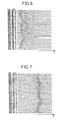
- Figures 6 and 7 show the signals that appear in a device implementing the method according to the invention, with a matrix of 121 transducers, in the case of a medium containing a single target very reflective.
- Figure 6 shows the variation in the time of the echo signals provided by the thirty two transducers (transducer 1 being the farthest from the axis) in response to illumination by the transducer central only, i.e. the signals obtained during step (b) defined above.
- the signals are very asymmetrical and do not allow localization precise of the wavefront maximum.
- step (c) the echo signals received after the first time reversal (step (c)), illustrated in Figure 7, clearly show on the one hand the symmetrization, on the other hand the presence of a net maximum, allowing already a good approximation.
- the concentration of the beam on the target is still continues during any subsequent iterations, the echo signal being symmetrical at each iteration odd.
- the target is not centered relative to the transducer matrix, the maxima are aligned according to a oblique line.
- Figures 8 and 9 are similar to Figures 6 and 7, but correspond to the case of three targets distributed in the middle; Figure 10 is obtained after five reversals temporal.
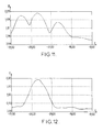
- Figures 11 and 12 show, on the ordinate, the sound pressure measured in the target plane.
- the targets had the same distribution as in the case of Figures 8, 9 and 10 and were three in number.
- Figure 11 shows the pressure distribution acoustics obtained after the first time reversal: the presence of three maxima corresponding to the three targets already appears clearly. This localization disappears at the outcome of the second time reversal.
- Figures 13 and 14 show, by way of example, the results obtained with a network of 121 transducers and an observed environment identical to that which gives rise to signals of figures 8 to 10.
- the search for maxima from signals of Figure 10 gives the distribution shown in Figure 13 where we note the presence of outliers, such as those surrounded by a circle in mixed lines.
- the forehead wave represented by samples in figure 13 calculates the coordinates of the target. Then at from the theoretical coordinate model it is possible synthesize the wavefront by emitting pulses having the relative arrangement shown in figure 14, which corresponds to the approximation by a sphere.
- the time window it is possible to find the time window to use by performing, over the duration of the signals received, the sum of the envelopes signals received on each channel, i.e. a inconsistent sum, to verify that the resulting signal has a local maximum in the selected window.
- Figure 15 shows the shape of the variation in sum S of the signals received on the different channels, after a reversal, in the case of a network and a medium studied constituted by a solid block having a localized defect in volume.
- the simple time lag of ultrasound signals can be replaced by a convolution operation between ultrasound signals 44 and signals 46 constituting the time signals of the transmission signals (figure 17).
- the convolution products, obtained in convolvers 48, are added in a summator 50.
Landscapes
- Engineering & Computer Science (AREA)
- Physics & Mathematics (AREA)
- Acoustics & Sound (AREA)
- General Physics & Mathematics (AREA)
- Radar, Positioning & Navigation (AREA)
- Remote Sensing (AREA)
- Computer Networks & Wireless Communication (AREA)
- Multimedia (AREA)
- Investigating Or Analyzing Materials By The Use Of Ultrasonic Waves (AREA)
- Measurement Of Velocity Or Position Using Acoustic Or Ultrasonic Waves (AREA)
- Ultra Sonic Daignosis Equipment (AREA)
- Surgical Instruments (AREA)
- Transducers For Ultrasonic Waves (AREA)
Description
L'invention a pour objet un procédé et un dispositif d'examen acoustique d'un milieu (le terme acoustique devant être pris dans un sens général, sans limitation aux fréquences audibles) pour repérer des cibles présentant une impédance acoustique différente de celle du milieu environnant.The subject of the invention is a method and a device acoustic examination of a medium (the acoustic term before be taken in a general sense, without limitation to frequencies audible) to identify targets with acoustic impedance different from that of the surrounding environment.
L'invention est applicable dans de nombreux domaines de la technique, parmi lesquels on peut citer :
- la détection et le repérage de défauts, tels que faille, crique, fissure et hétérogénéité de structures cristallographiques, dans des matériaux variés tels que les métaux, les composites et les céramiques, pour des objets de forme quelconque,
- la recherche d'objets solides en milieu marin ou dans les sédiments tapissant le fond de masses d'eau,
- le repérage d'hétérogénéités dans le sol,
- la localisation d'objets à saisir par un robot.
- detection and identification of faults, such as faults, cracks, cracks and heterogeneity of crystallographic structures, in various materials such as metals, composites and ceramics, for objects of any shape,
- the search for solid objects in the marine environment or in the sediments lining the bottom of bodies of water,
- the identification of heterogeneities in the soil,
- the location of objects to be grabbed by a robot.
On connaít déjà (EP-A-0 383 650) un procédé d'examen
acoustique non destructif d'un milieu suivant le préambule de la
revendication 1. We already know (EP-A-0 383 650) an examination process
non-destructive acoustics of a medium according to the preamble of the
Il suffit d'un faible nombre d'itérations pour faire apparaítre uniquement les signaux réfléchis par le réflecteur le plus important du milieu ou par le point le plus réfléchissant d'une cible réflectrice étendue, sous forme d'un ensemble de signaux ayant un maximum prononcé sur chacune des voies de réception correspondant chacune à un des voies de réception correspondant chacune à un des transducteurs du réseau.A small number of iterations is enough to do appear only the signals reflected by the reflector the most important in the middle or by the most reflective point of an extended reflecting target, in the form of a set of signals with a maximum pronounced on each of the reception each corresponding to one of the reception channels each corresponding to one of the network transducers.
Dans des modes particuliers de mise en oeuvre du procédé défini ci-dessus, la répartition dans le temps des maxima des signaux est mémorisée en vue d'une utilisation ultérieure. Dans un autre mode de réalisation, l'échelonnement dans le temps des signaux est déterminé par l'intercorrélation entre couples de signaux. Cette dernière solution exige cependant des calculs lourds. L'une et l'autre des solutions ne donnent pas une indication directement interprétable sur l'emplacement de la cible ou des cibles présentes dans le milieu.In particular modes of implementing the method defined above, the distribution over time of the maxima of signals are stored for later use. In another embodiment, the timing over time of signals is determined by the cross-correlation between couples of signals. The latter solution however requires calculations heavy. Either solution does not provide indication directly interpretable on the location of the target or targets present in the environment.
La présente invention vise notamment à fournir un procédé pouvant être appliqué à la détection de cibles réfléchissantes, à leur localisation, à l'imagerie échographique ultrasonore, et éventuellement à l'insonification (c'est-à-dire à la concentration d'énergie acoustique) d'une cible, répondant mieux que les procédés antérieurement connus aux exigences de la pratique.The present invention aims in particular to provide a process that can be applied to target detection reflective, to their location, to imagery ultrasound ultrasound, and possibly insonification (i.e. energy concentration acoustic) of a target, responding better than the processes previously known to the requirements of practice.
Plus précisément, l'invention vise notamment, bien que non exclusivement, à résoudre divers problèmes liés à la technique du retournement temporel tel que défini ci-dessus. Jusqu'à présent, ce retournement temporel n'avait été envisagé que pour provoquer une autofocalisation qui se traduit par une focalisation optimale d'une émission en présence d'une cible. En d'autres termes, le procédé était destiné à créer une pression acoustique maximale à l'emplacement de la cible. Mais, pour beaucoup d'applications, il reste nécessaire ou du moins souhaitable de localiser la cible dans l'espace, une fois que la présence d'une cible a été reconnue. En particulier, il est souvent souhaitable de caractériser la cible précédemment détectée en formant une image de type échographique.More specifically, the invention aims in particular, although not exclusively, to solve various problems related to time reversal technique as defined above. Until now, this time reversal had not been envisaged only to cause a self-focusing which results in a optimal focusing of a program in the presence of a target. In other words, the process was intended to create a maximum sound pressure at the target location. But, for many applications, it remains necessary or at least desirable to locate the target in space, once the presence of a target has been recognized. In particular, it is often desirable to characterize the target previously detected by forming an ultrasound type image.
Cela rend nécessaire une autofocalisation en réception.This makes self-focusing on reception necessary.
Par ailleurs le procédé défini plus haut, s'il donne des résultats favorables, présente en contrepartie une limitation lorsque l'on souhaite augmenter le nombre des itérations : les signaux échographiques deviennent de plus en plus longs au fur et à mesure que l'on répète les séquences de retournement temporel, ce qui se traduit par une perte de résolution axiale préjudiciable dans certains cas à la qualité des images.Furthermore, the process defined above, if it gives favorable results, in return presents a limitation when you want to increase the number of iterations: the ultrasound signals get longer and longer as and as we repeat the flipping sequences temporal, which results in a loss of axial resolution detrimental in some cases to the quality of the images.
Pour améliorer cette résolution axiale et ainsi mieux
focaliser en émission, l'invention propose les dispositions
énoncées dans la partie caractérisante de la revendication 1.To improve this axial resolution and thus better
focus in emission, the invention proposes the arrangements
set out in the characterizing part of
Cette solution permet notamment, une fois une cible repérée, de synthétiser un faisceau ultrasonore intense convergent vers le point le plus réfléchissant de la cible, notamment dans le cas où l'on cherche à détruire cette cible.This solution allows in particular, once a target identified, to synthesize an intense ultrasonic beam converge on the most reflective point of the target, especially in the case where one seeks to destroy this target.
La loi de retard temporel obtenue peut également être utilisée pour sommer l'ensemble des signaux de réception après les avoir recalés par application de la loi de retard, sur toute la durée de la fenêtre temporelle (revendication 3). On peut ainsi synthétiser la surface d'one optimale, puis ultérieurement effectuer une focalisation en émission et/ou en réception.The temporal delay law obtained can also be used to sum all the reception signals after having failed them by application of the delay law, on any the duration of the time window (claim 3). We can thus synthesize the optimal one area, then subsequently focus on transmission and / or reception.
On a constaté qu'en présence de cible réfléchissante, dans la zone sélectionnée par choix d'une fenêtre temporelle, un nombre impair de retournements temporels donne naissance, sur chaque voie, à un signal échographique de forme symétrique, ayant un maximum correspondant au mieux à l'emplacement du front d'onde dû à la réflexion sur la cible, ou en d'autre termes à la surface de ce front d'onde acoustique.We observed that in the presence of reflective target, in the area selected by choosing a time window, an odd number of time reversals gives rise, on each channel, to an ultrasound signal of symmetrical shape, having a maximum corresponding best to the location of the wavefront due to reflection from the target, or in other words on the surface of this acoustic wavefront.
C'est pourquoi, après avoir éventuellement vérifié la présence d'un front d'onde et après un dernier retournement temporel d'ordre 2n+1 (où n est un nombre entier positif et nul) sur toute la profondeur d'une fenêtre temporelle de mesure, on détermine les caractéristiques du front d'onde passant au plus près des maxima desdits signaux, avantageusement sous la forme de la répartition temporelle des maxima, qui souvent pourra être approximée par une loi polynomiale.This is why, after having possibly checked the presence of a wavefront and after a last reversal temporal order 2n + 1 (where n is a positive integer and zero) over the entire depth of a measurement time window, we determines the characteristics of the wave front passing at most near the maxima of said signals, advantageously in the form of the temporal distribution of the maxima, which often can be approximated by a polynomial law.
On peut en déduire les retards temporels pour chaque transducteur, qui permettent de reconstituer ce front d'onde à l'émission. On peut par ailleurs faire la somme des signaux recalés par application desdits retards temporels pour réaliser une localisation.We can deduce the time delays for each transducer, which make it possible to reconstruct this wavefront at the show. We can also add up the signals failed by application of said time delays to achieve a location.
Dans un mode avantageux de réalisation, on affecte des mémoires numériques de réception à chaque voie, c'est-à-dire à chaque transducteur utilisé à la réception et on détermine les instants d'arrivée des maxima de signal sur chaque transducteur par scrutation du contenu des adresses successives des mémoires affectées aux échantillons.In an advantageous embodiment, it affects digital reception memories for each channel, i.e. at each transducer used at the reception and the times of arrival of the signal maxima on each transducer by scanning the content of the successive addresses of the memories assigned to samples.
Un autre aspect de l'invention se rapporte à un
dispositif tel que défini dans la revendication 16.Another aspect of the invention relates to a
device as defined in
Comme on l'a indiqué plus haut, la détermination de la position relative des maxima et le recalage des signaux en émission et/ou en réception ne doivent en général être effectués que si on a bien constaté d'abord la présence d'un front d'onde provenant d'une cible dans la fenêtre où sont effectués d'abord la mesure, puis le retournement temporel. De façon générale, la fenêtre de retournement temporel est choisie pour correspondre aux parties intéressantes du milieu à explorer. As noted above, determining the relative position of the maxima and the registration of the signals in transmission and / or reception should generally not be carried out that if we have first noticed the presence of a wave front from a target in the window where are performed first the measurement, then the time reversal. In general, the time reversal window is chosen to match to the interesting parts of the environment to explore.
La fenêtre peut être connue a priori, par exemple dans le cas où une cible a été préalablement repérée par échographie ou radiologie X. Elle peut également être déterminée en évaluant de façon grossière le temps de vol correspondant à la cible sélectionnée. L'emplacement et la largeur de la fenêtre temporelle sont choisis de façon que les signaux dus à la réflexion ou à la diffraction sur cette cible soient à coup sûr inclus dans la fenêtre. On peut encore, comme par exemple dans la recherche de défauts dans un matériau de grande épaisseur, diviser la profondeur d'exploration en plusieurs fenêtres et vérifier après plusieurs itérations de retournement temporel, s'il existe des échos importants au sein de la fenêtre. On peut pour cela, après chaque itération, effectuer, sur toute la durée des signaux dans la fenêtre, la somme incohérente des signaux reçus sur chaque voie et vérifier si le signal résultant présente un maximum local dans la fenêtre. La procédure de recherche des maxima sur chaque voie est alors subordonnée au résultat favorable d'une procédure de comparaison du signal résultant à un seuil déterminé.The window can be known a priori, for example in the event that a target has been previously identified by ultrasound or X-ray. It can also be determined by roughly evaluating flight time corresponding to the selected target. The location and width of the time window are chosen so that signals due to reflection or diffraction on this target are definitely included in the window. We can again, as for example in the search for faults in thick material, divide the depth explore multiple windows and check after several iterations of time reversal, if there is one significant echoes within the window. We can for this, after each iteration, perform, over the entire duration signals in the window, the inconsistent sum of signals received on each channel and check if the signal resulting has a local maximum in the window. The procedure for finding the maxima on each channel is then subject to the favorable outcome of a comparison of the resulting signal with a determined threshold.
Une autre procédure encore consiste à comparer les signaux reçus dans la fenêtre pour deux itérations successives. Cette dernière procédure est particulièrement intéressante dans le cas où on recherche la présence de défauts au sein d'un milieu diffusant formé de petites hétérogénéités réparties de façon dense et aléatoire. Les alliages de titane, les matériaux composites, les aciers à grains constituent des exemples de tels milieux. Si les signaux captés par les transducteurs du réseau proviennent d'une cible réfléchissante, leurs structures spatiales resteront pratiquement inchangées d'un tir au suivant. Si on contraire les signaux recueillis au cours de deux tirs successifs ne sont pas corrélés, c'est qu'ils proviennent de diffuseurs qui sont trop imbriqués dans le milieu pour pouvoir être séparés par l'opération de retournement temporel. Yet another procedure is to compare the signals received in the window for two successive iterations. This last procedure is particularly interesting when looking for the presence of faults in the within a diffusing medium formed of small heterogeneities distributed in a dense and random manner. Alloys of titanium, composite materials, grain steels constitute examples of such environments. If the signals captured by the network transducers come from a reflective target, their spatial structures will remain practically unchanged from one shot to the next. If we the signals collected during two successive shots do not are not correlated is that they come from diffusers that are too nested in the middle to be able to be separated by the time reversal operation.
Une mesure de la corrélation ou du degré de ressemblance
entre les signaux d'écho provenant de deux itérations
successives peut être obtenue par sommation des coefficients
d'intercorrélation de deux tirs consécutifs, pour chacun des
transducteurs. Si on désigne par Ek p(t) le signal reçu dans
la fenêtre temporelle lors de l'itération p par le transducteur
d'ordre k et par Ek p+1(t) le signal reçu lors de l'itération
p+1, la fonction de corrélation c(τ) totale entre les
deux tirs s'écrit :

Le coefficient de corrélation est égal à la valeur du maximum de c(τ). Lorsque ce maximum est proche de 1, on peut on déduire que la fenêtre contient une cible réfléchissante. Lorsqu'il est inférieur à un seuil déterminé, sélectionné en fonction des conditions expérimentales et par exemple égal à 0,5, on peut en déduire que le milieu observé est diffusant et ne contient pas de cible prépondérante.The correlation coefficient is equal to the value of the maximum of c (τ). When this maximum is close to 1, we we can deduce that the window contains a reflective target. When it is below a determined threshold, selected according to the experimental conditions and by example equal to 0.5, we can deduce that the observed environment is diffusing and does not contain a predominant target.
Lorsque les transducteurs sont séparés du milieu par une interface, les fenêtres temporelles (qui peuvent être les mêmes ou différentes lors de tirs successifs) seront choisies de façon à éliminer les échos sur l'interface proprement dit, ainsi que sur un interface arrière éventuel.When the transducers are separated from the medium by an interface, time windows (which can be the same or different on successive shots) will be chosen to eliminate echoes on the interface itself, as well as on a possible rear interface.
Les opérations ci-dessus peuvent être considérées comme destinées à rechercher la présence d'une cible éventuelle. Il reste à repérer ou à localiser la cible, et éventuellement à en former une image.The above operations can be considered as intended to search for the presence of a target possible. It remains to locate or locate the target, and eventually to form an image.
Lorsque l'on désire caractériser la cible en en fournissant une image, on peut mettre en oeuvre un procédé d'échographie fournissant une image de la zone entourant la cible qui génère le front d'onde repéré, en déterminant les positions temporelles relatives des maxima du front d'onde.When we want to characterize the target by providing an image, we can implement a process ultrasound providing an image of the area surrounding the target that generates the identified wavefront, determining the relative time positions of the wavefront maxima.
Pour cela, on peut utiliser divers procédés.Various methods can be used for this.
On peut notamment former une image de la première ligne de l'image échographique (celle qui est centrée sur la cible) en émettant un front d'onde d'illumination répondant à une excitation de durée très brève, par exemple d'environ une demi-période acoustique, en excitant les transducteurs dans un ordre complémentaire des retards, c'est-à-dire que le transducteur ayant reçu un signal à un instant τ sera excité à un instant T0-τ, To étant une constante. On somme ensuite l'ensemble des signaux de réception, recalés par application des retards temporels.In particular, it is possible to form an image of the first line of the ultrasound image (that which is centered on the target) by emitting an illumination wavefront responding to an excitation of very short duration, for example of approximately half a -acoustic period, by exciting the transducers in an order complementary to the delays, that is to say that the transducer having received a signal at a time τ will be excited at a time T 0 -τ, T o being a constant. We then add up all the reception signals, readjusted by application of the time delays.
Une autre approche consiste à effectuer une exploration sectorielle autour de la première ligne de l'image. Pour cela on modifie la loi des retards préalablement trouvée en en faisant la somme avec une autre loi de retard correspondant à une déviation du faisceau ultrasonore d'un angle faible, suivant la technique dit des réseaux de phase. En utilisant la nouvelle loi de retard en émission et en réception, on obtient alors, en sommant de nouveau les signaux reçus, une image échographique focalisée dans une direction faisant un angle par rapport à l'axe de la cible.Another approach is to perform an exploration by sector around the first line of the image. For this we modify the law of delays beforehand found by adding it up with another delay law corresponding to a deflection of the ultrasonic beam of a low angle , using the technique known as phase. Using the new transmission delay law and in reception, we then obtain, by summing the received signals, an ultrasound image focused in a direction making an angle relative to the axis of the target.
Par application de lois de retard correspondant à des angulations différentes, on obtient une image par balayage séquentiel.By applying delay laws corresponding to different angles, we get an image by sequential scanning.
Dans une autre variante encore, on émet non plus des impulsions brèves identiques sur chaque voie, mais des signaux dont chacun est le retourné temporel du signal reçu à la dernière itération, au cours d'un intervalle temporel relativement bref (quelques périodes) centré autour des maxima.In yet another variant, no more identical brief pulses on each channel, but signals each of which is the time return of the received signal at the last iteration, during a time interval relatively brief (a few periods) centered around maxima.
La focalisation latérale est alors meilleure que celle résultant de l'émission d'une simple surface d'onde, mais en contrepartie on réduit la résolution axiale. The lateral focus is then better than that resulting from the emission of a simple wave surface, but in return we reduce the axial resolution.
Cette variante est particulièrement utile lorsqu'il est nécessaire de refocaliser à travers des milieux fortement inhomogènes, car elle améliore la refocalisation latérale. Elle résulte du fait que la focalisation optimale en un point est obtenue en ré-émettant un "volume d'onde" plutôt qu'une surface d'onde.This variant is particularly useful when is necessary to refocus through strongly inhomogeneous, because it improves refocusing lateral. It results from the fact that the optimal focus at a point is obtained by re-emitting a "wave volume" rather than a wave surface.
Pour la même raison, il peut être avantageux d'améliorer la focalisation en réception, surtout dans le cas d'un milieu inhomogène, en faisant le produit de convolution des signaux échographiques et des retournés temporels des signaux d'émission. Ce remplacement d'une simple opération de décalage temporel interdit l'utilisation de simples lignes à retard au profit de moyens matériels ou logiciels de convolution mais il donne un signal échographique plus intense pour une énergie donnée émise par l'ensemble des transducteurs, grâce à la sommation sur toutes les voies des produits de convolution. La lourdeur des calculs nécessaires n'est cependant justifiée que pour des milieux fortement inhomogènes.For the same reason, it can be beneficial improve focus in reception, especially in case of an inhomogeneous medium, by making the product of convolution of ultrasound signals and returns transmission signals. This replacement of a simple time shift operation prohibits use simple delay lines in favor of material means or convolution software but it gives an ultrasound signal more intense for a given energy emitted by the whole transducers, thanks to the summation on all convolution pathways. The heaviness of the calculations necessary is however only justified for environments strongly inhomogeneous.
Là encore il est possible de décaler angulairement les lignes de focalisation en décalant les signaux d'émission et/ou de réception par une loi de retard appropriée. Ce décalage peut notamment être effectué lorsqu'on met en oeuvre des convolueurs numériques, par un décalage temporel qui se traduit par un décalage dans la lecture des positions en mémoire contenant les signaux à émettre, avant convolution.Again it is possible to shift angularly focus lines by shifting emission signals and / or receipt by an appropriate delay law. This shift can especially be done when setting digital convolvers, by a time shift which results in a shift in the reading of the positions in memory containing the signals to be transmitted, before convolution.
Comme on l'a indiqué plus haut, des calculs complexes ne sont généralement pas nécessaires dans le cas de milieux faiblement inhomogènes. Il suffit alors d'effectuer la focalisation et la synthèse d'une surface d'onde à partir de la position des maxima.As mentioned above, complex calculations are generally not necessary in the case of slightly inhomogeneous environments. Then just perform focusing and synthesis of a wave surface from of the position of the maxima.
Dans ce cas on peut même souvent assimiler le front d'onde à une surface géométrique de forme simple au moyen d'une méthode d'optimisation mathématique au sens d'un critère déterminé, tel que celui des moindres carrés. In this case we can even often assimilate the forehead waveform to a geometric surface of simple shape using of a mathematical optimization method in the sense of a determined criterion, such as that of least squares.
Le problème est encore simplifié dans le cas particulier d'un milieu pratiquement homogène, car le front d'onde provenant d'un point peut alors être assimilé à une surface sphérique.The problem is further simplified in the case particular of a practically homogeneous medium, because the forehead wave from a point can then be assimilated to a spherical surface.
On peut alors assimiler la loi de répartition des maxima à celle de la sphère qui lui correspond le mieux, suivant un critère prédéterminé, tel que celui des moindres carrés des écarts.We can then assimilate the distribution law of maxima to that of the sphere which best corresponds to it, according to a predetermined criterion, such as that of the least squares of the deviations.
Une évaluation de la validité de l'approximation peut être faite en déterminant la variance des écarts. Si elle est suffisamment faible, on peut corriger ainsi les erreurs expérimentales.An assessment of the validity of the approximation can be done by determining the variance of the deviations. Yes it is low enough, we can correct the experimental errors.
Cela est particulièrement souhaitable lorsque, au cours d'une étape finale, on reproduit la répartition des retards correspondant au front d'onde assimilé à une sphère, pour concentrer une énergie ultra-sonore sur la cible la plus réfléchissante.This is particularly desirable when, at the during a final stage, we reproduce the distribution of delays corresponding to the wave front assimilated to a sphere, to focus ultrasonic energy on the target the more reflective.
Il est par ailleurs possible, dans la plupart des cas, de déduire par le calcul les caractéristiques de la sphère des résultats fournis par un petit nombre des transducteurs d'un réseau et d'en déduire les retards à appliquer à chacun des transducteurs du réseau, à l'émission, pour focaliser l'énergie sur une cible qui peut être décalée latéralement par rapport à l'axe du réseau. Dans le cas d'un milieu homogène, on peut ainsi mettre en oeuvre l'invention en n'équipant de moyens de retournement temporel que les voies de mesure de quelques transducteurs.It is also possible, in most case, to deduce by calculation the characteristics of the sphere of results provided by a small number of transducers in a network and deduce the delays apply to each of the transducers in the network, on transmission, to focus the energy on a target which can be laterally offset from the network axis. In the case of a homogeneous medium, one can thus implement the invention by equipping it with time reversal means than the measurement channels of some transducers.
L'invention sera mieux comprise à la lecture de la description qui suit d'un mode particulier de réalisation, donné à titre d'exemple non limitatif. La description se réfère aux dessins qui l'accompagnent, dans lesquels :
- les figures 1, 2
et 3 sont des schémas de principe montrant trois phases successives de mise en oeuvre du procédé suivant l'invention incluant des chronogrammes montrant l'allure des signaux électriques respectivement : appliqué à au moins un transducteur (figure 1) lors du premier tir ; obtenus à partir du premier tir (figure 2) ; et appliqués aux transducteurs (figure 3) après un retournement temporel ; - la figure 3A montre un mode de synthétisation de front d'onde sphérique ;
- la figure 4 est un schéma de principe d'une voie de mesure associée à un transducteur particulier dans un dispositif selon un mode particulier de réalisation de l'invention ;
- la figure 5 montre une disposition matricielle possible des transducteurs dans un dispositif permettant de mettre en oeuvre l'invention ;
- la figure 6 est un chronogramme montrant les signaux d'écho fournis par trente deux des transducteurs constituant un réseau suivant le schéma de la figure 5, à la première réflexion sur une cible unique étendue (calcul biliaire par exemple) située dans le milieu étudié, en réponse à l'envoi d'une impulsion par le transducteur central ;
- la figure 7 est un chronogramme montrant les signaux reçus par les mêmes trente deux transducteurs parmi ceux ayant la disposition matricielle de la figure 5, après le premier retournement temporel ;
- les figures 8
et 9, similaires aux figures 6et 7, montrent les signaux obtenus dans un milieu contenant trois cibles de tailles différentes, en forme de billes ; - la figure 10, similaire à la figure 9, montre les signaux d'écho après cinq retournements temporels accompagnés chacun d'un fenêtrage ;
- les figures 11 et 12 montrent le champ de pression mesuré dans le plan contenant trois cibles et obtenu par émission du retourné temporel des signaux des figures 8 et 10, respectivement après un premier retournement et après cinq retournements et, dans ce dernier cas, avec activation des transducteurs suivant une loi "sphérique", dans le cas d'un dispositif dont les transducteurs sont répartis au sein du réseau de la figure 5 ;
- la figure 13 montre une répartition dans le temps des maxima des diverses voies de la figure 10, dans le cas d'un même milieu que celui ayant donné naissance aux signaux des figures 8 à 10 ;
- la figure 14 montre la répartition dans le temps des signaux émis pour reconstituer une surface d'onde sphérique qui approxime au mieux la répartition de la figure 13 ;
- les figures 15 et 16 montrent la variation dans le temps t de la somme incohérente (figure 15) et de la somme cohérente (figure 16) des signaux reçus sur les différentes voies dans le cas de signaux d'écho provenant d'un milieu solide présentant deux interfaces nets et un défaut localisé en volume, au stade du retour d'une émission au niveau de la figure 3 ;
- la figure 17 montre un mode de sommation, après produit de convolution des signaux reçus après une émission à retournement temporel par les signaux retournés d'émission.
- Figures 1, 2 and 3 are block diagrams showing three successive phases of implementation of the method according to the invention including timing diagrams showing the shape of the electrical signals respectively: applied to at least one transducer (Figure 1) during first shot; obtained from the first shot (Figure 2); and applied to the transducers (Figure 3) after a time reversal;
- FIG. 3A shows a mode of synthesizing a spherical wavefront;
- Figure 4 is a block diagram of a measurement channel associated with a particular transducer in a device according to a particular embodiment of the invention;
- FIG. 5 shows a possible matrix arrangement of the transducers in a device making it possible to implement the invention;
- FIG. 6 is a timing diagram showing the echo signals supplied by thirty two of the transducers constituting a network according to the diagram of FIG. 5, at the first reflection on a single extended target (gallstones for example) located in the environment studied, in response to the sending of a pulse by the central transducer;
- FIG. 7 is a timing diagram showing the signals received by the same thirty two transducers from those having the matrix arrangement of FIG. 5, after the first time reversal;
- Figures 8 and 9, similar to Figures 6 and 7, show the signals obtained in a medium containing three targets of different sizes, in the form of beads;
- FIG. 10, similar to FIG. 9, shows the echo signals after five time reversals each accompanied by windowing;
- FIGS. 11 and 12 show the pressure field measured in the plane containing three targets and obtained by sending the time feedback of the signals of FIGS. 8 and 10, respectively after a first reversal and after five reversals and, in the latter case, with activation transducers according to a "spherical" law, in the case of a device whose transducers are distributed within the network of FIG. 5;
- FIG. 13 shows a distribution over time of the maxima of the various channels of FIG. 10, in the case of the same medium as that which gave rise to the signals of FIGS. 8 to 10;
- FIG. 14 shows the distribution over time of the signals transmitted to reconstruct a spherical wave surface which approximates the distribution of FIG. 13 as best as possible;
- Figures 15 and 16 show the variation over time t of the inconsistent sum (Figure 15) and the coherent sum (Figure 16) of the signals received on the different channels in the case of echo signals from a solid medium having two clear interfaces and a fault located in volume, at the stage of the return of a transmission at the level of FIG. 3;
- FIG. 17 shows a summation mode, after product of convolution of the signals received after a time-reversal transmission by the returned transmission signals.
L'invention est susceptible d'être mise en oeuvre à l'aide d'un dispositif du genre décrit dans le document EP-A-0 383 650, déjà mentionné. En conséquence, ce dispositif ne sera que sommairement décrit ici.The invention is capable of being implemented in using a device of the kind described in the document EP-A-0 383 650, already mentioned. As a result, this device will only be briefly described here.
Comme le montrent les figures 1 à 3, la mise en
oeuvre du procédé selon l'invention est destinée à provoquer
la formation progressive d'un champ de pression acoustique
convergeant vers la cible principale 10 placée dans un
milieu 18.As shown in Figures 1 to 3, the implementation
work of the process according to the invention is intended to cause
progressive formation of a sound pressure field
converging on the
Au cours d'une étape (a), on illumine la zone dans
laquelle se trouve la cible 10 à localiser à l'aide d'un
faisceau large non focalisé (figure 1). Sur la figure 1, ce
faisceau est fourni par le transducteur central d'une
matrice 12 de transducteurs ultra-sonores 1, 2,..., i,...,
n (avec n = 64 par exemple) qui sera utilisée au cours des
étapes suivantes. Ces transducteurs seront souvent répartis
suivant une matrice à deux dimensions, bien que les transducteurs
soient montrés suivant une seule ligne. La matrice
peut être plane ou concave. Elle peut être à réseau rectangulaire.
Les transducteurs peuvent également être répartis
suivant des cercles concentriques, comme indiqué sur la
figure 5, ou même suivant une répartition lacunaire dans
l'espace.During a step (a), the area is illuminated in
which is the
Il est également possible d'utiliser quelques
transducteurs de la matrice, ou même tous, pour la première
illumination. Dans le cas montré sur la figure 1, le
transducteur central est excité, au cours de la première
illumination, par un circuit 14. On obtient ainsi un
faisceau non focalisé éclairant la cible 10, située dans un
milieu 18.It is also possible to use some
matrix transducers, or even all, for the first
illumination. In the case shown in Figure 1, the
central transducer is excited, during the first
illumination, by a
Le circuit 14 peut être un générateur d'impulsions
brèves attaquant un ou plusieurs transducteurs.
Au cours d'une étape (b), on capte le signal d'écho
reçu par les transducteurs de la matrice 12 et on mémorise
la forme et la position relative dans le temps t des
signaux, à l'aide d'un circuit 16 (figure 2). Ces premiers
signaux d'écho ont par exemple la forme montrée en figure 2
lorsque le signal électrique d'excitation de l'étape (a) est
une impulsion brève.During a step (b), the echo signal received by the transducers of the
L'examen, par exemple sur un oscilloscope ou un
moniteur de télévision, des signaux reçus permet de sélectionner
une fenêtre temporelle de durée T contenant la
quasi-totalité de l'énergie réfléchie et recueillie par les
transducteurs de la matrice 12. Ce sont uniquement les
signaux contenus dans cette fenêtre temporelle qui seront
mémorisés dans le circuit 16.The examination, for example on an oscilloscope or a
television monitor, received signals selects
a time window of duration T containing the
almost all of the energy reflected and collected by
Au cours d'une étape (c), on retourne temporellement une première fois les signaux recueillis pendant la fenêtre temporelle T et on les ré-émet (figure 3) avec un gain d'amplification qui peut être le même pour tous les transducteurs. Il est réglé de façon automatique pour respecter une condition : aucune des voies ne doit être saturée en réception.During a step (c), we return in time the signals collected during the window for the first time time T and we re-emit them (figure 3) with a gain which can be the same for all transducers. It is automatically adjusted to respect one condition: none of the channels must be saturated in reception.
Le front d'onde ainsi constitué est automatiquement
symétrisé et l'écho reçu en retour par les transducteurs de
la matrice 12 apparaítra, à la sortie de chacun de ces
transducteurs, sous forme d'un signal symétrique par rapport
à une valeur centrale maximale. Si le processus de retournement
temporel et de mémorisation des échos est répété
plusieurs fois, on recueillera, à chaque étape impaire, des
signaux symétriques sur chaque voie de détection associée à
un transducteur et en même temps, il se produira une
concentration progressive de l'énergie sur la cible la plus
importante, dans la mesure où le milieu contient plusieurs
cibles, ou sur la partie la plus réfléchissante d'une cible.The wavefront thus formed is automatically
balanced and the echo received back by the transducers
the
Il est alors possible de déterminer, à partir des
signaux recueillis lors de la dernière itération impaire
effectuée, la ligne ou la surface géométrique simple 40
(telle qu'une sphère) la plus proche du front d'onde 42
défini comme la surface passant par les maxima des différents
signaux.It is then possible to determine, from the
signals collected during the last odd iteration
performed, the simple geometric line or surface 40
(such as a sphere) closest to the
L'intérêt de faire une approximation du front d'onde sous forme d'une surface ou une courbe géométrique simple est de permettre de déterminer aisément le centre ou le foyer de la surface et de connaítre exactement la position de la zone la plus réfléchissante de la cible.The advantage of making a wavefront approximation as a surface or a simple geometric curve is to allow easy determination of the center or focus of the surface and know exactly the position of the most reflective area of the target.
Cela permet de compléter le procédé par une étape finale adaptée à l'application envisagée.This completes the process with one step final adapted to the envisaged application.
Dans le cas où l'opération finale consiste en une
opération de destruction, elle peut être effectuée avec une
très forte amplification du signal appliqué à chaque
transducteur et recalage de chacun des signaux par application
d'un retard correspondant à la focalisation au centre
de la surface 40.In the event that the final transaction consists of
destruction operation, it can be carried out with a
very strong amplification of the signal applied to each
transducer and registration of each signal by application
a delay corresponding to the focus in the center
from
Dans ce cas, la probabilité que le centre de la
sphère corresponde à l'emplacement d'une zone de la cible à
détruire devra généralement être proche de 100%. Pour
atteindre cette quasi-certitude, une vérification sera
généralement effectuée : elle consiste à déterminer la
variance des écarts entre la surface 40 et les emplacements
des maxima. On écarte alors la surface 40 en tant que
représentation du front d'onde lorsque la variance dépasse
une valeur prédéterminée.In this case, the probability that the center of the
sphere corresponds to the location of an area of the target at
destroy will generally have to be close to 100%. For
achieve this near certainty, a verification will
generally performed: it consists in determining the
variance of deviations between
D'autres applications rendent souhaitable une
évaluation de la taille de la cible. Pour cela, on peut
notamment mémoriser les retards correspondant au front
d'onde centré sur la zone la plus réfléchissante de la cible
10, puis effectuer des tirs avec des retards modifiés
suivant une loi du type réseau de phase sectoriel pour
correspondre à une focalisation sur des points ayant un
décalage latéral. Pour chaque répartition de retards à
l'émission on peut aussi effectuer une focalisation en
réception en décalant tous les signaux de réception, suivant
la loi des retards d'émission retournée et sommation sur
tous les canaux. Suivant l'angle, on retrouve la figure 9 ou
10 qui permet une représentation en mode échographie B ou C
à partir des retards de la figure 14 qui est un mode A.Other applications make it desirable
evaluation of the size of the target. For that, we can
in particular memorize the delays corresponding to the front
wave centered on the most reflective area of the
La taille de la pièce peut être évaluée à partir de la distance d au-delà de laquelle l'amplitude maximale est inférieure à un seuil s.The size of the part can be evaluated from the distance d beyond which the maximum amplitude is less than a threshold s .
La recherche de la surface géométrique 40, représentable
par une équation polynomiale, correspondant au mieux
au front d'onde 42 peut s'effectuer par un procédé classique
d'approximation polynomiale et en général on utilisera la
méthode des moindres carrés.The search for the representable
L'invention peut être mise en oeuvre en utilisant un
dispositif dans lequel chaque voie de mesure 20 associée à
un transducteur d'ordre i a la constitution montrée en
figure 4. La voie 20 comporte un échantillonneur 22 qui
fournit des échantillons analogiques du signal reçu par le
transducteur i, à la fréquence d'une horloge 24, pendant les
fenêtres temporelles T fixées par le cadenceur 26. Les
échantillons numérisés par un convertisseur 28 sont mémorisés
dans une mémoire 30 organisée en pile d'attente ou LIFO. The invention can be implemented using a device in which each
Le cadenceur 26 est programmé de façon à provoquer
l'émission du front d'onde retourné au bout d'un délai
déterminé après la fin de l'écho.The
Pour appliquer au transducteur i le signal retourné,
la voie 20 comprend un convertisseur numérique/analogique 32
suivi d'un amplificateur 34. Pour compenser l'absorption
dans le milieu, la voie 20 représentée comprend un amplificateur
38 suivi d'un atténuateur 40 dont le coefficient
d'atténuation est modifié en fonction du temps, par un
programmateur 42 qui contient la fonction inverse de
l'exponentielle négative d'absorption dans le milieu.To apply the returned signal to the transducer i , the
Le dispositif comprend encore des moyens de calcul
36 pour accéder à la mémoire 30 en lecture et en écriture,
permettant de déterminer, pour chaque signal mémorisé,
l'emplacement temporel du maximum, contenant un programme de
détermination de la surface ayant la meilleure correspondance
possible avec la répartition temporelle des maxima
obtenue par lecture des mémoires 30 et permettant éventuellement
de modifier, dans chaque mémoire 30, la valeur et la
position temporelle des échantillons de façon à faire
exactement correspondre le dernier tir à l'approximation
géométrique effectuée du front d'onde.The device also includes calculation means
36 to access
L'électronique du dispositif peut avoir d'autres constitutions que celle montrée en figure 4. En particulier, il est possible d'utiliser une disposition du genre décrit dans la demande de brevet FR 91 13629 où chaque voie comprend successivement un amplificateur logarithmique à commande de gain, un convertisseur analogique-numérique qui échantillonne le signal et quantifie chaque échantillon. Le signal numérisé peut être communiqué à un bus vidéo permettant la visualisation. Il est également appliqué à un ensemble de mémorisation et de compensation de profondeur ayant une mémoire vive et un additionneur-soustracteur permettant d'ajouter au signal une rampe numérique mémorisée. La voie sera complétée par un détecteur de signe placé à l'entrée de l'amplificateur logarithmique. Device electronics may have other constitutions as that shown in Figure 4. In particular, it is possible to use a layout of the kind described in patent application FR 91 13629 where each channel successively comprises a logarithmic amplifier with gain control, an analog-to-digital converter that samples the signal and quantifies each sample. The digitized signal can be communicated to a video bus allowing visualization. It is also applied to a depth storage and compensation set having a RAM and an adder-subtractor allowing to add to the signal a memorized digital ramp. The track will be completed by a sign detector placed at the input of the logarithmic amplifier.
Dans ce cas, la partie du dispositif consacrée à la ré-émission comprend un circuit d'exponentiation (mémoire vive par exemple). Les signaux numériques obtenus sont dépourvus de signe du fait de la conversion logarithmique. Un signe leur est affecté, par exemple par ajout d'un bit de signe dans la mémoire. Ce bit est fourni par le détecteur de signe. La mémoire est lue en retournement temporel. Les échantillons numériques polarisés lus en mémoire sont mis sous forme analogique par un convertisseur numérique-analogique, et appliqués à un amplificateur linéaire attaquant le transducteur d'où provient le signal.In this case, the part of the device devoted to re-transmission includes an exponentiation circuit (memory long live for example). The digital signals obtained are devoid of sign due to logarithmic conversion. A sign is assigned to them, for example by adding a bit of sign in memory. This bit is supplied by the sign. The memory is read in time reversal. The polarized digital samples read into memory are put in analog form by a digital-analog converter, and applied to a linear amplifier attacking the transducer from which the signal comes.
Comme on l'a indiqué plus haut, les transducteurs peuvent être répartis suivant des matrices de natures très diverses.As noted above, the transducers can be distributed according to matrices of very different natures various.
La figure 5 montre, à titre d'exemple, une matrice à 121 transducteurs, numérotés de 0 à 120.Figure 5 shows, as an example, a matrix with 121 transducers, numbered from 0 to 120.
Les figures 6 et 7 montrent les signaux qui apparaissent
dans un dispositif mettant en oeuvre le procédé
suivant l'invention, avec une matrice de 121 transducteurs,
dans le cas d'un milieu contenant une seule cible très
réfléchissante. La figure 6 montre la variation dans le
temps des signaux d'écho fournis par les trente deux
transducteurs (le transducteur 1 étant le plus éloigné de
l'axe) en réponse à une illumination par le transducteur
central uniquement, c'est-à-dire les signaux obtenus lors de
l'étape (b) définie plus haut. On constate que les signaux
sont très dissymétriques et ne permettent pas une localisation
précise du maximum du front d'onde.Figures 6 and 7 show the signals that appear
in a device implementing the method
according to the invention, with a matrix of 121 transducers,
in the case of a medium containing a single target very
reflective. Figure 6 shows the variation in the
time of the echo signals provided by the thirty two
transducers (
Au contraire, les signaux d'écho reçus après le premier retournement temporel (étape (c)), illustrés en figure 7, font clairement apparaítre d'une part la symétrisation, d'autre part la présence d'un maximum net, permettant déjà une bonne approximation.On the contrary, the echo signals received after the first time reversal (step (c)), illustrated in Figure 7, clearly show on the one hand the symmetrization, on the other hand the presence of a net maximum, allowing already a good approximation.
La concentration du faisceau sur la cible se poursuit encore lors des itérations suivantes éventuelles, le signal d'écho étant symétrique à chaque itération impaire.The concentration of the beam on the target is still continues during any subsequent iterations, the echo signal being symmetrical at each iteration odd.
La cible n'étant pas centrée par rapport à la matrice de transducteur, les maxima s'alignent suivant une ligne oblique.The target is not centered relative to the transducer matrix, the maxima are aligned according to a oblique line.
Les figures 8 et 9 sont similaires aux figures 6 et 7, mais correspondent au cas de trois cibles réparties dans le milieu ; la figure 10 est obtenue après cinq retournements temporels.Figures 8 and 9 are similar to Figures 6 and 7, but correspond to the case of three targets distributed in the middle; Figure 10 is obtained after five reversals temporal.
Les figures 11 et 12 montrent, en ordonnées, la pression acoustique mesurée dans le plan des cibles. Les cibles présentaient la même répartition que dans le cas des figures 8, 9 et 10 et étaient au nombre de trois.Figures 11 and 12 show, on the ordinate, the sound pressure measured in the target plane. The targets had the same distribution as in the case of Figures 8, 9 and 10 and were three in number.
La figure 11 montre la répartition de pression acoustique obtenue après le premier retournement temporel : la présence de trois maxima correspondant aux trois cibles apparaít déjà nettement. Cette localisation disparaít à l'issue du second retournement temporel.Figure 11 shows the pressure distribution acoustics obtained after the first time reversal: the presence of three maxima corresponding to the three targets already appears clearly. This localization disappears at the outcome of the second time reversal.
Au fur et à mesure que l'on passe d'une itération impaire à la suivante, l'effet de focalisation sur la cible la plus importante s'accentue et, après le cinquième retournement, l'approximation du front d'onde par une sphère et la ré-émission avec une loi de retard correspondant au centre de la sphère, on arrive à la répartition de pression acoustique montrée en figure 12.As we go from one iteration odd to the next, the focus effect on the target the most important increases and, after the fifth reversal, the approximation of the wavefront by a sphere and re-transmission with a delay law corresponding to center of the sphere, we arrive at the pressure distribution acoustics shown in Figure 12.
Les figures 13 et 14 montrent, à titre d'exemple, les résultats obtenus avec un réseau à 121 transducteurs et un milieu observé identique à celui qui donne naissance aux signaux des figures 8 à 10. La recherche des maxima à partir des signaux de la figure 10, par exemple par détermination des adresses des échantillons de valeur maximale, donne la répartition montrée en figure 13 où l'on note la présence de points aberrants, tels que ceux entourés par un cercle en traits mixtes. En écartant ces points aberrants, le front d'onde représenté par des échantillons sur la figure 13 permet de calculer les coordonnées de la cible. Puis, à partir du modèle théorique des coordonnées, il est possible de synthétiser le front d'onde par émission d'impulsions ayant la disposition relative montrée en figure 14, qui correspond à l'approximation par une sphère.Figures 13 and 14 show, by way of example, the results obtained with a network of 121 transducers and an observed environment identical to that which gives rise to signals of figures 8 to 10. The search for maxima from signals of Figure 10, for example by determination addresses of samples of maximum value, gives the distribution shown in Figure 13 where we note the presence of outliers, such as those surrounded by a circle in mixed lines. By removing these outliers, the forehead wave represented by samples in figure 13 calculates the coordinates of the target. Then at from the theoretical coordinate model it is possible synthesize the wavefront by emitting pulses having the relative arrangement shown in figure 14, which corresponds to the approximation by a sphere.
Comme on l'a indiqué plus haut, il est possible de rechercher la fenêtre temporelle à utiliser en effectuant, sur toute la durée des signaux reçus, la somme des enveloppes des signaux reçus sur chaque voie, c'est-à-dire une somme incohérente, afin de vérifier que le signal résultant présente un maximum local dans la fenêtre choisie.As mentioned above, it is possible to find the time window to use by performing, over the duration of the signals received, the sum of the envelopes signals received on each channel, i.e. a inconsistent sum, to verify that the resulting signal has a local maximum in the selected window.
La figure 15 montre l'allure de la variation de la somme S des signaux reçus sur les différentes voies, après un retournement, dans le cas d'un réseau et d'un milieu étudié constitué par un bloc solide ayant un défaut localisé en volume.Figure 15 shows the shape of the variation in sum S of the signals received on the different channels, after a reversal, in the case of a network and a medium studied constituted by a solid block having a localized defect in volume.
On peut également effectuer la somme cohérente des signaux, c'est-à-dire une somme après recalage temporel et dans ce cas, on arrive à une répartition du genre montré en figure 16 qui met encore mieux en évidence la présence des cibles.We can also perform the coherent sum of signals, i.e. a sum after time registration and in this case, we arrive at a gender distribution shown in Figure 16 which highlights the presence of targets.
Enfin, lorsqu'une focalisation optimale en réception
de signaux provenant d'un milieu inhomogène est nécessaire,
le simple décalage temporel des signaux échographiques peut
être remplacé par une opération de convolution entre les
signaux échographiques 44 et les signaux 46 constituant les
retournés temporels des signaux d'émission (figure 17). Les
produits de convolution, obtenus dans des convolueurs
individuels 48, sont additionnés dans un sommateur 50. On
utilisera alors en général des systèmes numériques et on
pourra adapter la fenêtre temporelle ΔT utilisée pour chaque
voie afin qu'elle soit optimale.Finally, when optimal focus in reception
of signals from an inhomogeneous medium is necessary,
the simple time lag of ultrasound signals can
be replaced by a convolution operation between
ultrasound signals 44 and signals 46 constituting the
time signals of the transmission signals (figure 17). The
convolution products, obtained in
Claims (17)
- Method of non-destructive acoustic (sound or ultrasound) inspection of a medium for localizing reflective targets, comprising the steps of:wherein, after a last time-reversal, the characteristics of a wave front closest to the maxima of the reflected signals is determined,(a) illuminating the medium (18) with a highly divergent acoustic beam from at least one transducer;(b) detecting the signals reflected by the medium and received by a plurality of transducers (1,...,n) belonging to an array (12);(c) selecting by means of a time window (T), the echo signals reflected by a particular zone of said medium and storing them in digital form;(d) time-reversing and re-transmitting said echo signals;(e) storing the new reflected echo signals and repeating the time reversal operation,
characterized by (f) forming a last illumination wave front by emitting, on all the channels each corresponding to one of the plurality of transducers, signals having the same shape and of very short duration, at times defined for each transducer by a delay complementary of the time distribution of said maxima, the first maxima corresponding to the signals of very short duration emitted at last,
in that the last time-reversal is of order 2n+1 (where n is a positive or null integer), and in that, after said last time-reversal, characteristics of a simple geometric surface closest to the maxima of the reflected signal and representative of the wave front of the last received echoes is determined. - Method according to claim 1, characterized by summing the reflected echo signals from signals offset by applying said time delays over the whole depth of a measurement time window (fig. 16).
- Method according to claim 1 or 2, characterized in that, the medium having an interface, the reflected signals during step (c) are only stored during a time window which discards the echoes on said interface.
- Method according to claim 1, characterized by the further step of exploring sectorwise the target corresponding to the maxima, while maintaining a transmission and reception focussing by combining said delays with another delay law.
- Method according to any one of claims 1 to 4, characterized by the preliminary step of determining said window (T) by incoherently summing the echoes from said illumination and selecting said time window so that it includes the maxima of all the echo signals.
- Method according to any one of claim 1 to 4, characterized by the step of arbitrarily selecting the time window from information available on the depth of possible targets (10) in the medium.
- Method according to any one of the preceding claims, characterized by determining the characteristics of a simple geometrical surface, such as a sphere best matching said wave front according to a given criterion which can be represented by a polynomial equation.
- Method according to any one of the preceding claims, characterized in that the criterion is the least square criterion.
- Method according to claim 8, characterized by the step of determining the variance of the deviation and by the step of discarding said surface as the representation of the wave front when the variance exceeds a predetermined value.
- Method according to claim 7, 8 or 9, characterized in that, in a subsequent step, the delay distribution corresponding to said surface is reproduced to focus ultrasound energy onto the most important target.
- Method according to claim 7, 8 or 9, characterized in that the surface being a sphere, calculations are made to deduce, from the characteristics of the sphere, the location of its center and the delays to be applied to the signals provided to each of the transducers so as to focus the energy transmitted by the transducers to a position laterally shifted with respect to said center.
- Method according to any one of claims 1 to 11, characterized by the step of searching a reflective target (10) by comparing the echo signals received during two successive time-reversal iterations.
- Method according to claim 12, characterized in that the similarity between signals received in successive iterations is determined by comparing to a threshold, the measurement of cross-correlation coefficients of two consecutive transmissions, for each of the transducers.
- Method according to any one of claims 1 to 4, characterized by the step of computing, on reception, the convolution product of the echo signals and of the time reversed transmitted signals.
- Method according to any one of the preceding claims, characterized in that during step (c), the analog echo signals from the transducers are submitted to a logarithmic amplification; the amplified echo signals are stored as digital samples with a sign bit, and a digital depth compensation digital ramp is added to said samples, and in that, during step (d), the sign is reaffected to the compensated samples, the samples are digitally exponentiated and a digital-analog conversion is carried out before retransmission by the respective transducers.
- Device for acoustically examining a medium and locating reflective targets, comprising:characterized in that said circuit (16) comprises means (36) to determine the characteristics of a geometrical surface closest to the maxima of the signals and representing a wave front, and means to form a last illumination wave front by emitting, on all the channels each corresponding to one of the plurality of the transducers, signals having the same shape and of very short direction at times defined for each transducers by a delay complementary of the time distribution of said maxima, the first maxima corresponding to the signals of short duration emitted at last.a plurality of emitter-receiver transducers constituting a transducer array (12);a circuit (16) connected to the transducers and arranged for, after a first transmission toward the medium, repeating an odd number of times a sequence including: receiving echo signals through said transducers, storing said signals, and re-emitting the stored signals after time reversal,
- Device according to claim 16, characterized in that:said circuit comprises, for each transducer (1,...,i,...,n) a processing channel (20) having a sampler (22), an analog-digital converter (28), a stack-type memory (30), a digital-analog converter and means for amplification and attenuation compensation (38,40,42,34), andsaid computation means are arranged and programmed for read and write access to each of the memories (30) in said channels and to modify the values and the time distribution of the stored samples for them to correspond to the geometrical approximation of the wave front.
Applications Claiming Priority (2)
| Application Number | Priority Date | Filing Date | Title |
|---|---|---|---|
| FR9211659 | 1992-10-02 | ||
| FR9211659A FR2696573B1 (en) | 1992-10-02 | 1992-10-02 | TIME-RETURN ACOUSTIC EXAMINATION METHOD AND DEVICE. |
Publications (2)
| Publication Number | Publication Date |
|---|---|
| EP0591061A1 EP0591061A1 (en) | 1994-04-06 |
| EP0591061B1 true EP0591061B1 (en) | 1999-08-04 |
Family
ID=9434051
Family Applications (2)
| Application Number | Title | Priority Date | Filing Date |
|---|---|---|---|
| EP93921972A Withdrawn EP0615625A1 (en) | 1992-10-02 | 1993-09-30 | Therapy device for destroying a target by acoustic signals featuring time reversal |
| EP93402409A Expired - Lifetime EP0591061B1 (en) | 1992-10-02 | 1993-10-01 | Method and device for acoustic examination with time reversal |
Family Applications Before (1)
| Application Number | Title | Priority Date | Filing Date |
|---|---|---|---|
| EP93921972A Withdrawn EP0615625A1 (en) | 1992-10-02 | 1993-09-30 | Therapy device for destroying a target by acoustic signals featuring time reversal |
Country Status (9)
| Country | Link |
|---|---|
| US (1) | US5428999A (en) |
| EP (2) | EP0615625A1 (en) |
| JP (1) | JP3623246B2 (en) |
| CA (1) | CA2107525C (en) |
| DE (1) | DE69325868T2 (en) |
| ES (1) | ES2137238T3 (en) |
| FR (1) | FR2696573B1 (en) |
| IL (1) | IL107159A (en) |
| WO (1) | WO1994008253A1 (en) |
Families Citing this family (69)
| Publication number | Priority date | Publication date | Assignee | Title |
|---|---|---|---|---|
| FR2728352A1 (en) * | 1994-12-20 | 1996-06-21 | Giat Ind Sa | METHOD FOR DETECTING OBJECTS DISTRIBUTED IN A FIELD AREA OR DETERMINING THE PROPAGATION PROPAGATION CHARACTERISTICS OF AN ACOUSTIC WAVE IN THE SOIL AND DEVICE IMPLEMENTING SAID METHODS |
| FR2728354A1 (en) * | 1994-12-20 | 1996-06-21 | Giat Ind Sa | METHOD FOR DETECTION OF OBJECTS DISTRIBUTED IN A FIELD AREA AND DEVICE IMPLEMENTING SUCH A METHOD |
| WO1997003438A1 (en) * | 1995-07-13 | 1997-01-30 | Societe Pour Les Applications Du Retournement Temporel | Acoustic wave focusing method and device |
| FR2749938B1 (en) * | 1996-06-13 | 1998-08-28 | Fink Mathias | METHOD AND DEVICE FOR DETECTION AND LOCATION OF REFLECTIVE SOUND SOURCE |
| EP1330815A2 (en) * | 2000-03-15 | 2003-07-30 | The Regents Of The University Of California | Method and apparatus for dynamic focusing of ultrasound energy |
| JP4484351B2 (en) * | 2000-10-20 | 2010-06-16 | 株式会社荏原製作所 | Nondestructive inspection method and apparatus |
| JP4176329B2 (en) * | 2001-06-06 | 2008-11-05 | 三菱重工業株式会社 | Object search method and object search apparatus |
| US6755083B2 (en) * | 2001-06-13 | 2004-06-29 | The Regents Of The University Of California | Method for distinguishing multiple targets using time-reversal acoustics |
| US7460605B2 (en) * | 2001-11-15 | 2008-12-02 | Lawrence Livermore National Security, Llc | Time reversal communication system |
| US6876597B2 (en) | 2002-01-30 | 2005-04-05 | James K. Bullis | Channeled wavefield transformer |
| US20040059265A1 (en) * | 2002-09-12 | 2004-03-25 | The Regents Of The University Of California | Dynamic acoustic focusing utilizing time reversal |
| US7463690B2 (en) * | 2002-11-06 | 2008-12-09 | Lawrence Livermore National Security, Llc | Multi-channel time-reversal receivers for multi and 1-bit implementations |
| US20040162507A1 (en) | 2003-02-19 | 2004-08-19 | Assaf Govari | Externally-applied high intensity focused ultrasound (HIFU) for therapeutic treatment |
| FR2851662B1 (en) | 2003-02-24 | 2006-08-25 | Socomate Internat | METHOD AND DEVICE FOR DETECTING DISCONTINUITIES IN A MEDIUM |
| AU2003901538A0 (en) * | 2003-03-28 | 2003-05-01 | Cochlear Limited | Maxima search method for sensed signals |
| NO325153B1 (en) * | 2003-05-05 | 2008-02-11 | Clampon As | Method and system for recording structural conditions in an acoustically conductive material using cross-reflections |
| US20050154306A1 (en) * | 2004-01-14 | 2005-07-14 | Michael Burcher | Dort process-based method and system for adaptive beamforming in estimating the aberration in a medium |
| US7421298B2 (en) * | 2004-09-07 | 2008-09-02 | Cochlear Limited | Multiple channel-electrode mapping |
| US20060241523A1 (en) * | 2005-04-12 | 2006-10-26 | Prorhythm, Inc. | Ultrasound generating method, apparatus and probe |
| JP4576281B2 (en) * | 2005-04-15 | 2010-11-04 | 株式会社日立エンジニアリング・アンド・サービス | Ultrasonic inspection method |
| US20070038060A1 (en) * | 2005-06-09 | 2007-02-15 | Cerwin Stephen A | Identifying and treating bodily tissues using electromagnetically induced, time-reversed, acoustic signals |
| US7713200B1 (en) | 2005-09-10 | 2010-05-11 | Sarvazyan Armen P | Wireless beacon for time-reversal acoustics, method of use and instrument containing thereof |
| US20070167805A1 (en) * | 2005-10-28 | 2007-07-19 | Clement Gregory T | Ultrasound Imaging |
| JP4928930B2 (en) * | 2006-12-14 | 2012-05-09 | 三菱重工業株式会社 | Ultrasonic flaw detection apparatus and ultrasonic flaw detection method |
| CN100593719C (en) * | 2006-12-31 | 2010-03-10 | 南京航空航天大学 | Method for investigating failure connection of engineering structure by signal focus |
| FR2912817B1 (en) * | 2007-02-21 | 2009-05-22 | Super Sonic Imagine Sa | METHOD FOR OPTIMIZING WAVE FOCUSING THROUGH AN INTRODUCING ELEMENT OF ABERATIONS |
| JP5150125B2 (en) * | 2007-03-30 | 2013-02-20 | 日本電気株式会社 | Detection apparatus, detection program, and detection method |
| US7928896B2 (en) * | 2007-07-09 | 2011-04-19 | Carnegie Mellon University | Application of time reversal to synthetic aperture imaging |
| JP5123644B2 (en) * | 2007-11-15 | 2013-01-23 | 三菱重工業株式会社 | Ultrasonic flaw detection method and ultrasonic flaw detection apparatus |
| JP5332187B2 (en) * | 2007-11-29 | 2013-11-06 | 日本電気株式会社 | Underwater object shape recognition method, underwater object shape recognition device, underwater object shape recognition program, and program recording medium |
| GB0723622D0 (en) * | 2007-12-04 | 2008-01-09 | Univ Exeter The | Devices, systems and methods of detecting defects in workpieces |
| JP2009204572A (en) * | 2008-02-29 | 2009-09-10 | Kyoto Univ | Position measuring device and its method |
| US8545405B2 (en) * | 2008-04-23 | 2013-10-01 | Therataxis, Llc | Device, methods, and control for sonic guidance of molecules and other material utilizing time-reversal acoustics |
| US10447094B2 (en) | 2016-05-03 | 2019-10-15 | Origin Wireless, Inc. | Method, system, and apparatus for wireless power transmission based on power waveforming |
| US9887864B1 (en) | 2014-03-10 | 2018-02-06 | Origin Wireless, Inc. | Methods, devices and systems of heterogeneous time-reversal paradigm enabling direct connectivity in internet of things |
| US11025475B2 (en) | 2012-12-05 | 2021-06-01 | Origin Wireless, Inc. | Method, apparatus, server, and systems of time-reversal technology |
| US10440705B2 (en) | 2012-12-05 | 2019-10-08 | Origin Wireless, Inc. | Method, apparatus, server, and systems of time-reversal technology |
| US9883511B1 (en) | 2012-12-05 | 2018-01-30 | Origin Wireless, Inc. | Waveform design for time-reversal systems |
| US10291460B2 (en) | 2012-12-05 | 2019-05-14 | Origin Wireless, Inc. | Method, apparatus, and system for wireless motion monitoring |
| US10609711B1 (en) | 2015-03-05 | 2020-03-31 | Origin Wireless, Inc. | Time-reversal scalability for high network densification |
| US10129862B1 (en) | 2016-02-16 | 2018-11-13 | Origin Wireless, Inc. | Methods, devices, apparatus, and systems for medium access control in wireless communication systems utilizing spatial focusing effect |
| US9226304B2 (en) | 2014-03-10 | 2015-12-29 | Origin Wireless, Inc. | Time-reversal wireless paradigm for internet of things |
| US10168414B2 (en) | 2014-07-17 | 2019-01-01 | Origin Wireless, Inc. | Wireless signals and techniques for determining locations of objects in multi-path environments |
| US9882675B2 (en) | 2013-08-16 | 2018-01-30 | Origin Wireless, Inc. | Time-reversal wireless systems having asymmetric architecture |
| US9407306B2 (en) | 2014-04-25 | 2016-08-02 | Origin Wireless, Inc. | Quadrature amplitude modulation for time-reversal systems |
| US9559874B2 (en) | 2013-08-16 | 2017-01-31 | Origin Wireless, Inc. | Multiuser time-reversal division multiple access uplink system with parallel interference cancellation |
| US9686054B2 (en) | 2014-07-17 | 2017-06-20 | Origin Wireless, Inc. | Joint waveform design and interference pre-cancellation for time-reversal systems |
| US10014982B1 (en) | 2015-01-22 | 2018-07-03 | Origin Wireless, Inc. | Time-reversal technologies for hybrid wireless networks |
| US8411765B2 (en) | 2008-10-10 | 2013-04-02 | Ziva Corporation | Techniques and systems for wireless communications |
| US8582397B2 (en) * | 2009-01-06 | 2013-11-12 | Therataxis, Llc | Creating, directing and steering regions of intensity of wave propagation in inhomogeneous media |
| CN101645264B (en) * | 2009-07-17 | 2012-03-14 | 中国科学院声学研究所 | Optimal active time-reversal focusing method based on iterative least square/pre-filtering |
| EP2474102A4 (en) | 2009-09-03 | 2016-06-22 | Ziva Corp | Techniques and systems for communications based on time reversal pre-coding |
| US8337433B2 (en) | 2010-05-24 | 2012-12-25 | Stephen Anthony Cerwin | Time-reversed mirroring electro-magnetic acoustic treatment system |
| FR2977671B1 (en) | 2011-07-08 | 2013-11-29 | 01Db Metravib | METHOD AND DEVICE FOR CONTROLLING TEMPORARY RETURN STRUCTURES |
| US9110166B2 (en) | 2011-12-01 | 2015-08-18 | Halliburton Energy Services, Inc. | Acoustic imaging |
| US10270642B2 (en) | 2012-12-05 | 2019-04-23 | Origin Wireless, Inc. | Method, apparatus, and system for object tracking and navigation |
| US10122409B2 (en) | 2012-12-03 | 2018-11-06 | University Of Maryland At College Park | Systems and methods for time-reversal division multiple access wireless broadband communications |
| US9313020B2 (en) | 2014-02-19 | 2016-04-12 | Origin Wireless, Inc. | Handshaking protocol for time-reversal system |
| US10327213B1 (en) | 2015-10-01 | 2019-06-18 | Origin Wireless, Inc. | Time-reversal communication systems |
| KR101462175B1 (en) * | 2013-01-10 | 2014-11-20 | 삼성전자주식회사 | Ultrasonic imaging apparatus and method for controlling the same |
| WO2015128409A1 (en) | 2014-02-26 | 2015-09-03 | Institut National De La Sante Et De La Recherche Medicale (Inserm) | Shear wave generation method, shear wave imaging method and thermal mapping or treating method utilizing such a generation method and installation for generating at least one shear wave |
| WO2015164886A2 (en) | 2014-08-05 | 2015-10-29 | Waag Robert C | Device, system, and method for hemispheric breast imaging |
| DE102015204065A1 (en) | 2015-03-06 | 2016-09-08 | Otto-Von-Guericke-Universität Magdeburg | A guidewire for guiding an article to a destination in a hollow structure of a human or animal body |
| DE202015010011U1 (en) | 2015-03-06 | 2023-02-24 | Otto-von-Guericke-Universität Magdeburg, Körperschaft des öffentlichen Rechts | Guidewire for guiding an object to a target site in a hollow structure of a human or animal body |
| RU2611556C1 (en) * | 2015-11-09 | 2017-02-28 | Российская Федерация, От Имени Которой Выступает Министерство Промышленности И Торговли Российской Федерации | Method for determination of multiposition sonar system efficiency |
| US10380881B2 (en) | 2015-12-09 | 2019-08-13 | Origin Wireless, Inc. | Method, apparatus, and systems for wireless event detection and monitoring |
| US10852427B2 (en) | 2017-06-30 | 2020-12-01 | Gopro, Inc. | Ultrasonic ranging state management for unmanned aerial vehicles |
| CN109990968B (en) * | 2019-03-22 | 2021-01-05 | 西北核技术研究所 | Plate structure impact positioning method based on time reversal method principle |
| CN115670504B (en) * | 2022-10-24 | 2024-01-09 | 浙江衡玖医疗器械有限责任公司 | Method for judging quality of original signal of three-dimensional ultrasonic tomography system |
Family Cites Families (4)
| Publication number | Priority date | Publication date | Assignee | Title |
|---|---|---|---|---|
| US4463608A (en) * | 1979-05-07 | 1984-08-07 | Yokogawa Hokushin Electric Corp. | Ultrasound imaging system |
| CA1169145A (en) * | 1980-04-22 | 1984-06-12 | Julian Dow | Ultrasonic imaging system |
| FR2492109B1 (en) * | 1980-10-10 | 1985-07-05 | Thomson Csf | MULTIPLE AND SIMULTANEOUS EMISSION IMAGING SYSTEM |
| FR2642640B1 (en) * | 1989-02-08 | 1991-05-10 | Centre Nat Rech Scient | METHOD AND DEVICE FOR FOCUSING ULTRASOUND IN TISSUES |
-
1992
- 1992-10-02 FR FR9211659A patent/FR2696573B1/en not_active Expired - Fee Related
-
1993
- 1993-09-24 US US08/125,855 patent/US5428999A/en not_active Expired - Lifetime
- 1993-09-29 IL IL10715993A patent/IL107159A/en not_active IP Right Cessation
- 1993-09-30 JP JP24536393A patent/JP3623246B2/en not_active Expired - Lifetime
- 1993-09-30 EP EP93921972A patent/EP0615625A1/en not_active Withdrawn
- 1993-09-30 WO PCT/FR1993/000956 patent/WO1994008253A1/en not_active Application Discontinuation
- 1993-10-01 CA CA002107525A patent/CA2107525C/en not_active Expired - Lifetime
- 1993-10-01 DE DE69325868T patent/DE69325868T2/en not_active Expired - Lifetime
- 1993-10-01 ES ES93402409T patent/ES2137238T3/en not_active Expired - Lifetime
- 1993-10-01 EP EP93402409A patent/EP0591061B1/en not_active Expired - Lifetime
Also Published As
| Publication number | Publication date |
|---|---|
| US5428999A (en) | 1995-07-04 |
| ES2137238T3 (en) | 1999-12-16 |
| CA2107525C (en) | 2004-04-06 |
| JPH06341978A (en) | 1994-12-13 |
| IL107159A (en) | 1996-05-14 |
| IL107159A0 (en) | 1993-12-28 |
| DE69325868D1 (en) | 1999-09-09 |
| EP0591061A1 (en) | 1994-04-06 |
| EP0615625A1 (en) | 1994-09-21 |
| JP3623246B2 (en) | 2005-02-23 |
| DE69325868T2 (en) | 2000-04-13 |
| WO1994008253A1 (en) | 1994-04-14 |
| CA2107525A1 (en) | 1994-04-03 |
| FR2696573B1 (en) | 1996-08-30 |
| FR2696573A1 (en) | 1994-04-08 |
Similar Documents
| Publication | Publication Date | Title |
|---|---|---|
| EP0591061B1 (en) | Method and device for acoustic examination with time reversal | |
| EP0383650B1 (en) | Process and apparatus for locating and focusing waves | |
| EP0904535B1 (en) | Method and device for detecting and locating a reverberating source of sound | |
| CA2234465C (en) | Procedure and device for processing signals representative of waves reflected, transmitted or refracted by a 3-dimensional structure in order to explore and analyse the structure | |
| FR2851662A1 (en) | Medium e.g. linear probe, discontinuity detecting method for e.g. portable medical apparatus, involves applying coherence criteria to selected maxima for regrouping maxima to same discontinuity, where maxima has value higher than threshold | |
| EP0124442B1 (en) | Method and device for acoustic holographyx using an altrasonic beam limited in space | |
| EP2780699A1 (en) | Method for reconstructing the geometry of a surface of an object via echographic sounding, corresponding computer program and device for ultrasonic sounding | |
| EP3899523B1 (en) | Method for ultrasound imaging using two-dimensional fourier transform, corresponding ultrasound probe device and computer program | |
| FR2839157A1 (en) | ULTRASONIC IMAGING SYSTEM WITH HIGH SIDE RESOLUTION | |
| EP0718639A1 (en) | Process and device for detecting objects distributed in a field | |
| EP0099816B1 (en) | Method and apparatus for ultrasonic echography | |
| EP0825453B1 (en) | Method and apparatus for processing signals representative of waves which have been reflected by or transmitted through a volume structure, in order to enable exploration and analysis of said structure | |
| EP2342582B1 (en) | Method and device for probing by wave propagation | |
| FR3015742A1 (en) | METHOD FOR PROCESSING ULTRASONIC SURVEY ACQUISITION SIGNALS, COMPUTER PROGRAM, AND CORRESPONDING ULTRASONIC SURVEY DEVICE | |
| EP0718638B1 (en) | Method of detection of objects located in a ground area or of determination of the propagation characteristics of an acoustic wave in the ground, and system to carry out these methods | |
| WO2015075121A1 (en) | Method for reconstructing a surface of a part | |
| EP4127692A1 (en) | Non-destructive testing of a mechanical part made of a polycrystalline material | |
| FR2855271A1 (en) | Voluminous structure e.g. echograph, exploring process, involves detecting sign of signals that are detected from field memories, and detecting useful zone of decoding curve in which signals are of same sign | |
| FR2848674A1 (en) | Medical ultrasound echography control system uses tables of data to provide varying delays and phase shifts for beams contributing to image formation | |
| WO1997004333A1 (en) | Imaging method and device with parallel processing of data |
Legal Events
| Date | Code | Title | Description |
|---|---|---|---|
| PUAI | Public reference made under article 153(3) epc to a published international application that has entered the european phase |
Free format text: ORIGINAL CODE: 0009012 |
|
| AK | Designated contracting states |
Kind code of ref document: A1 Designated state(s): DE DK ES GB IT SE |
|
| 17P | Request for examination filed |
Effective date: 19940507 |
|
| 17Q | First examination report despatched |
Effective date: 19960103 |
|
| RAP1 | Party data changed (applicant data changed or rights of an application transferred) |
Owner name: SOCIETE POUR LES APPLICATIONS DU RETOURNEMENT TEMP |
|
| GRAG | Despatch of communication of intention to grant |
Free format text: ORIGINAL CODE: EPIDOS AGRA |
|
| GRAG | Despatch of communication of intention to grant |
Free format text: ORIGINAL CODE: EPIDOS AGRA |
|
| GRAH | Despatch of communication of intention to grant a patent |
Free format text: ORIGINAL CODE: EPIDOS IGRA |
|
| GRAH | Despatch of communication of intention to grant a patent |
Free format text: ORIGINAL CODE: EPIDOS IGRA |
|
| GRAA | (expected) grant |
Free format text: ORIGINAL CODE: 0009210 |
|
| AK | Designated contracting states |
Kind code of ref document: B1 Designated state(s): DE DK ES GB IT SE |
|
| PG25 | Lapsed in a contracting state [announced via postgrant information from national office to epo] |
Ref country code: GB Free format text: LAPSE BECAUSE OF FAILURE TO SUBMIT A TRANSLATION OF THE DESCRIPTION OR TO PAY THE FEE WITHIN THE PRESCRIBED TIME-LIMIT Effective date: 19990804 |
|
| REF | Corresponds to: |
Ref document number: 69325868 Country of ref document: DE Date of ref document: 19990909 |
|
| ITF | It: translation for a ep patent filed | ||
| PG25 | Lapsed in a contracting state [announced via postgrant information from national office to epo] |
Ref country code: DK Free format text: LAPSE BECAUSE OF FAILURE TO SUBMIT A TRANSLATION OF THE DESCRIPTION OR TO PAY THE FEE WITHIN THE PRESCRIBED TIME-LIMIT Effective date: 19991104 |
|
| REG | Reference to a national code |
Ref country code: ES Ref legal event code: FG2A Ref document number: 2137238 Country of ref document: ES Kind code of ref document: T3 |
|
| GBV | Gb: ep patent (uk) treated as always having been void in accordance with gb section 77(7)/1977 [no translation filed] |
Effective date: 19990804 |
|
| PLBE | No opposition filed within time limit |
Free format text: ORIGINAL CODE: 0009261 |
|
| STAA | Information on the status of an ep patent application or granted ep patent |
Free format text: STATUS: NO OPPOSITION FILED WITHIN TIME LIMIT |
|
| 26N | No opposition filed | ||
| PGFP | Annual fee paid to national office [announced via postgrant information from national office to epo] |
Ref country code: SE Payment date: 20120924 Year of fee payment: 20 |
|
| PGFP | Annual fee paid to national office [announced via postgrant information from national office to epo] |
Ref country code: IT Payment date: 20120921 Year of fee payment: 20 |
|
| PGFP | Annual fee paid to national office [announced via postgrant information from national office to epo] |
Ref country code: DE Payment date: 20120924 Year of fee payment: 20 |
|
| PGFP | Annual fee paid to national office [announced via postgrant information from national office to epo] |
Ref country code: ES Payment date: 20121005 Year of fee payment: 20 |
|
| REG | Reference to a national code |
Ref country code: DE Ref legal event code: R071 Ref document number: 69325868 Country of ref document: DE |
|
| REG | Reference to a national code |
Ref country code: SE Ref legal event code: EUG |
|
| PG25 | Lapsed in a contracting state [announced via postgrant information from national office to epo] |
Ref country code: DE Free format text: LAPSE BECAUSE OF EXPIRATION OF PROTECTION Effective date: 20131002 |
|
| REG | Reference to a national code |
Ref country code: ES Ref legal event code: FD2A Effective date: 20140925 |
|
| PG25 | Lapsed in a contracting state [announced via postgrant information from national office to epo] |
Ref country code: ES Free format text: LAPSE BECAUSE OF EXPIRATION OF PROTECTION Effective date: 20131002 |