EP4083659B1 - Device and method for processing the signal from a set of ultrasonic transducers - Google Patents
Device and method for processing the signal from a set of ultrasonic transducers Download PDFInfo
- Publication number
- EP4083659B1 EP4083659B1 EP22169557.0A EP22169557A EP4083659B1 EP 4083659 B1 EP4083659 B1 EP 4083659B1 EP 22169557 A EP22169557 A EP 22169557A EP 4083659 B1 EP4083659 B1 EP 4083659B1
- Authority
- EP
- European Patent Office
- Prior art keywords
- signal
- transducers
- pulses
- signals
- coherence
- Prior art date
- Legal status (The legal status is an assumption and is not a legal conclusion. Google has not performed a legal analysis and makes no representation as to the accuracy of the status listed.)
- Active
Links
- 238000012545 processing Methods 0.000 title claims description 129
- 238000000034 method Methods 0.000 title claims description 25
- 230000008878 coupling Effects 0.000 claims description 36
- 238000010168 coupling process Methods 0.000 claims description 36
- 238000005859 coupling reaction Methods 0.000 claims description 36
- 230000033001 locomotion Effects 0.000 claims description 28
- 238000005259 measurement Methods 0.000 claims description 24
- 230000009466 transformation Effects 0.000 claims description 22
- 238000002592 echocardiography Methods 0.000 claims description 21
- 238000013528 artificial neural network Methods 0.000 claims description 20
- 230000005540 biological transmission Effects 0.000 claims description 16
- 230000000630 rising effect Effects 0.000 claims description 11
- 230000008569 process Effects 0.000 claims description 6
- 238000007493 shaping process Methods 0.000 claims description 4
- 230000001131 transforming effect Effects 0.000 claims description 4
- 230000006978 adaptation Effects 0.000 claims description 3
- 230000001427 coherent effect Effects 0.000 claims description 3
- 238000005070 sampling Methods 0.000 claims description 3
- 230000004044 response Effects 0.000 claims description 2
- 238000001514 detection method Methods 0.000 description 35
- 238000010586 diagram Methods 0.000 description 17
- 238000002604 ultrasonography Methods 0.000 description 15
- 239000011159 matrix material Substances 0.000 description 12
- 230000001052 transient effect Effects 0.000 description 9
- 230000010363 phase shift Effects 0.000 description 8
- 230000005284 excitation Effects 0.000 description 5
- 238000001914 filtration Methods 0.000 description 5
- 230000006870 function Effects 0.000 description 5
- 238000012805 post-processing Methods 0.000 description 5
- 238000006243 chemical reaction Methods 0.000 description 4
- 230000004913 activation Effects 0.000 description 3
- 230000003321 amplification Effects 0.000 description 3
- 230000008901 benefit Effects 0.000 description 3
- 238000004364 calculation method Methods 0.000 description 3
- 230000000694 effects Effects 0.000 description 3
- 230000004807 localization Effects 0.000 description 3
- 238000003199 nucleic acid amplification method Methods 0.000 description 3
- 238000007781 pre-processing Methods 0.000 description 3
- 241000861223 Issus Species 0.000 description 2
- 238000013459 approach Methods 0.000 description 2
- 238000004590 computer program Methods 0.000 description 2
- 230000004069 differentiation Effects 0.000 description 2
- 239000006185 dispersion Substances 0.000 description 2
- 235000021183 entrée Nutrition 0.000 description 2
- 230000001976 improved effect Effects 0.000 description 2
- 239000000203 mixture Substances 0.000 description 2
- 210000002569 neuron Anatomy 0.000 description 2
- 230000000306 recurrent effect Effects 0.000 description 2
- 238000012421 spiking Methods 0.000 description 2
- 230000003068 static effect Effects 0.000 description 2
- 230000009471 action Effects 0.000 description 1
- 230000003213 activating effect Effects 0.000 description 1
- 230000004931 aggregating effect Effects 0.000 description 1
- 238000004891 communication Methods 0.000 description 1
- 238000010276 construction Methods 0.000 description 1
- 238000013527 convolutional neural network Methods 0.000 description 1
- 238000001739 density measurement Methods 0.000 description 1
- 230000001066 destructive effect Effects 0.000 description 1
- 238000003745 diagnosis Methods 0.000 description 1
- 230000008030 elimination Effects 0.000 description 1
- 238000003379 elimination reaction Methods 0.000 description 1
- 230000002349 favourable effect Effects 0.000 description 1
- 230000006872 improvement Effects 0.000 description 1
- 230000010354 integration Effects 0.000 description 1
- 230000002452 interceptive effect Effects 0.000 description 1
- 238000007477 logistic regression Methods 0.000 description 1
- 238000000691 measurement method Methods 0.000 description 1
- 230000003287 optical effect Effects 0.000 description 1
- 238000003909 pattern recognition Methods 0.000 description 1
- XEBWQGVWTUSTLN-UHFFFAOYSA-M phenylmercury acetate Chemical compound CC(=O)O[Hg]C1=CC=CC=C1 XEBWQGVWTUSTLN-UHFFFAOYSA-M 0.000 description 1
- 230000009467 reduction Effects 0.000 description 1
- 230000035945 sensitivity Effects 0.000 description 1
- 238000012706 support-vector machine Methods 0.000 description 1
- 230000002123 temporal effect Effects 0.000 description 1
- 238000012549 training Methods 0.000 description 1
- 230000001960 triggered effect Effects 0.000 description 1
- 238000010200 validation analysis Methods 0.000 description 1
Images


Classifications
-
- G—PHYSICS
- G01—MEASURING; TESTING
- G01S—RADIO DIRECTION-FINDING; RADIO NAVIGATION; DETERMINING DISTANCE OR VELOCITY BY USE OF RADIO WAVES; LOCATING OR PRESENCE-DETECTING BY USE OF THE REFLECTION OR RERADIATION OF RADIO WAVES; ANALOGOUS ARRANGEMENTS USING OTHER WAVES
- G01S7/00—Details of systems according to groups G01S13/00, G01S15/00, G01S17/00
- G01S7/52—Details of systems according to groups G01S13/00, G01S15/00, G01S17/00 of systems according to group G01S15/00
- G01S7/523—Details of pulse systems
- G01S7/526—Receivers
- G01S7/53—Means for transforming coordinates or for evaluating data, e.g. using computers
- G01S7/533—Data rate converters
-
- G—PHYSICS
- G01—MEASURING; TESTING
- G01S—RADIO DIRECTION-FINDING; RADIO NAVIGATION; DETERMINING DISTANCE OR VELOCITY BY USE OF RADIO WAVES; LOCATING OR PRESENCE-DETECTING BY USE OF THE REFLECTION OR RERADIATION OF RADIO WAVES; ANALOGOUS ARRANGEMENTS USING OTHER WAVES
- G01S7/00—Details of systems according to groups G01S13/00, G01S15/00, G01S17/00
- G01S7/52—Details of systems according to groups G01S13/00, G01S15/00, G01S17/00 of systems according to group G01S15/00
- G01S7/52003—Techniques for enhancing spatial resolution of targets
-
- G—PHYSICS
- G01—MEASURING; TESTING
- G01S—RADIO DIRECTION-FINDING; RADIO NAVIGATION; DETERMINING DISTANCE OR VELOCITY BY USE OF RADIO WAVES; LOCATING OR PRESENCE-DETECTING BY USE OF THE REFLECTION OR RERADIATION OF RADIO WAVES; ANALOGOUS ARRANGEMENTS USING OTHER WAVES
- G01S15/00—Systems using the reflection or reradiation of acoustic waves, e.g. sonar systems
- G01S15/88—Sonar systems specially adapted for specific applications
- G01S15/89—Sonar systems specially adapted for specific applications for mapping or imaging
- G01S15/8906—Short-range imaging systems; Acoustic microscope systems using pulse-echo techniques
-
- G—PHYSICS
- G01—MEASURING; TESTING
- G01S—RADIO DIRECTION-FINDING; RADIO NAVIGATION; DETERMINING DISTANCE OR VELOCITY BY USE OF RADIO WAVES; LOCATING OR PRESENCE-DETECTING BY USE OF THE REFLECTION OR RERADIATION OF RADIO WAVES; ANALOGOUS ARRANGEMENTS USING OTHER WAVES
- G01S15/00—Systems using the reflection or reradiation of acoustic waves, e.g. sonar systems
- G01S15/02—Systems using the reflection or reradiation of acoustic waves, e.g. sonar systems using reflection of acoustic waves
- G01S15/06—Systems determining the position data of a target
- G01S15/42—Simultaneous measurement of distance and other co-ordinates
-
- G—PHYSICS
- G01—MEASURING; TESTING
- G01S—RADIO DIRECTION-FINDING; RADIO NAVIGATION; DETERMINING DISTANCE OR VELOCITY BY USE OF RADIO WAVES; LOCATING OR PRESENCE-DETECTING BY USE OF THE REFLECTION OR RERADIATION OF RADIO WAVES; ANALOGOUS ARRANGEMENTS USING OTHER WAVES
- G01S7/00—Details of systems according to groups G01S13/00, G01S15/00, G01S17/00
- G01S7/52—Details of systems according to groups G01S13/00, G01S15/00, G01S17/00 of systems according to group G01S15/00
- G01S7/523—Details of pulse systems
- G01S7/526—Receivers
- G01S7/527—Extracting wanted echo signals
- G01S7/5273—Extracting wanted echo signals using digital techniques
-
- G—PHYSICS
- G01—MEASURING; TESTING
- G01S—RADIO DIRECTION-FINDING; RADIO NAVIGATION; DETERMINING DISTANCE OR VELOCITY BY USE OF RADIO WAVES; LOCATING OR PRESENCE-DETECTING BY USE OF THE REFLECTION OR RERADIATION OF RADIO WAVES; ANALOGOUS ARRANGEMENTS USING OTHER WAVES
- G01S7/00—Details of systems according to groups G01S13/00, G01S15/00, G01S17/00
- G01S7/52—Details of systems according to groups G01S13/00, G01S15/00, G01S17/00 of systems according to group G01S15/00
- G01S7/539—Details of systems according to groups G01S13/00, G01S15/00, G01S17/00 of systems according to group G01S15/00 using analysis of echo signal for target characterisation; Target signature; Target cross-section
-
- G—PHYSICS
- G06—COMPUTING; CALCULATING OR COUNTING
- G06F—ELECTRIC DIGITAL DATA PROCESSING
- G06F3/00—Input arrangements for transferring data to be processed into a form capable of being handled by the computer; Output arrangements for transferring data from processing unit to output unit, e.g. interface arrangements
- G06F3/01—Input arrangements or combined input and output arrangements for interaction between user and computer
- G06F3/017—Gesture based interaction, e.g. based on a set of recognized hand gestures
-
- G—PHYSICS
- G10—MUSICAL INSTRUMENTS; ACOUSTICS
- G10K—SOUND-PRODUCING DEVICES; METHODS OR DEVICES FOR PROTECTING AGAINST, OR FOR DAMPING, NOISE OR OTHER ACOUSTIC WAVES IN GENERAL; ACOUSTICS NOT OTHERWISE PROVIDED FOR
- G10K11/00—Methods or devices for transmitting, conducting or directing sound in general; Methods or devices for protecting against, or for damping, noise or other acoustic waves in general
- G10K11/18—Methods or devices for transmitting, conducting or directing sound
- G10K11/20—Reflecting arrangements
-
- G—PHYSICS
- G10—MUSICAL INSTRUMENTS; ACOUSTICS
- G10K—SOUND-PRODUCING DEVICES; METHODS OR DEVICES FOR PROTECTING AGAINST, OR FOR DAMPING, NOISE OR OTHER ACOUSTIC WAVES IN GENERAL; ACOUSTICS NOT OTHERWISE PROVIDED FOR
- G10K11/00—Methods or devices for transmitting, conducting or directing sound in general; Methods or devices for protecting against, or for damping, noise or other acoustic waves in general
- G10K11/18—Methods or devices for transmitting, conducting or directing sound
- G10K11/26—Sound-focusing or directing, e.g. scanning
- G10K11/34—Sound-focusing or directing, e.g. scanning using electrical steering of transducer arrays, e.g. beam steering
- G10K11/341—Circuits therefor
- G10K11/346—Circuits therefor using phase variation
-
- G—PHYSICS
- G01—MEASURING; TESTING
- G01S—RADIO DIRECTION-FINDING; RADIO NAVIGATION; DETERMINING DISTANCE OR VELOCITY BY USE OF RADIO WAVES; LOCATING OR PRESENCE-DETECTING BY USE OF THE REFLECTION OR RERADIATION OF RADIO WAVES; ANALOGOUS ARRANGEMENTS USING OTHER WAVES
- G01S15/00—Systems using the reflection or reradiation of acoustic waves, e.g. sonar systems
- G01S15/88—Sonar systems specially adapted for specific applications
- G01S15/89—Sonar systems specially adapted for specific applications for mapping or imaging
- G01S15/8906—Short-range imaging systems; Acoustic microscope systems using pulse-echo techniques
- G01S15/8909—Short-range imaging systems; Acoustic microscope systems using pulse-echo techniques using a static transducer configuration
- G01S15/8915—Short-range imaging systems; Acoustic microscope systems using pulse-echo techniques using a static transducer configuration using a transducer array
-
- G—PHYSICS
- G01—MEASURING; TESTING
- G01S—RADIO DIRECTION-FINDING; RADIO NAVIGATION; DETERMINING DISTANCE OR VELOCITY BY USE OF RADIO WAVES; LOCATING OR PRESENCE-DETECTING BY USE OF THE REFLECTION OR RERADIATION OF RADIO WAVES; ANALOGOUS ARRANGEMENTS USING OTHER WAVES
- G01S7/00—Details of systems according to groups G01S13/00, G01S15/00, G01S17/00
- G01S7/52—Details of systems according to groups G01S13/00, G01S15/00, G01S17/00 of systems according to group G01S15/00
- G01S7/52017—Details of systems according to groups G01S13/00, G01S15/00, G01S17/00 of systems according to group G01S15/00 particularly adapted to short-range imaging
- G01S7/52023—Details of receivers
- G01S7/52025—Details of receivers for pulse systems
- G01S7/52026—Extracting wanted echo signals
- G01S7/52028—Extracting wanted echo signals using digital techniques
-
- G—PHYSICS
- G01—MEASURING; TESTING
- G01S—RADIO DIRECTION-FINDING; RADIO NAVIGATION; DETERMINING DISTANCE OR VELOCITY BY USE OF RADIO WAVES; LOCATING OR PRESENCE-DETECTING BY USE OF THE REFLECTION OR RERADIATION OF RADIO WAVES; ANALOGOUS ARRANGEMENTS USING OTHER WAVES
- G01S7/00—Details of systems according to groups G01S13/00, G01S15/00, G01S17/00
- G01S7/52—Details of systems according to groups G01S13/00, G01S15/00, G01S17/00 of systems according to group G01S15/00
- G01S7/52017—Details of systems according to groups G01S13/00, G01S15/00, G01S17/00 of systems according to group G01S15/00 particularly adapted to short-range imaging
- G01S7/52023—Details of receivers
- G01S7/52036—Details of receivers using analysis of echo signal for target characterisation
Definitions
- the invention generally relates to the field of detection systems and in particular to a device and a method for processing the signal from a set of ultrasonic transducers.
- Ultrasonic sensors are today used in many applications such as spatial localization, gesture detection, fingerprint recognition, biomedical images, etc.
- An ultrasonic sensor emits short, high-frequency sound pulses at regular intervals. These pulses travel through the air at the speed of sound. When they encounter an object, they are reflected and return as an echo to the sensor. This then calculates the distance separating it from the target based on the time elapsed between the transmission of the signal and the reception of the echo.
- An ultrasonic sensor emits short, high-frequency sound pulses at regular intervals. These pulses travel through the air at the speed of sound. When they encounter an object, they are reflected and return as an echo to the sensor. This then calculates the distance separating it from the target based on the time elapsed between the transmission of the signal and the reception of the echo.
- An ultrasonic sensor emits short, high-frequency sound pulses at regular intervals.
- These pulses travel through the air at the speed of sound. When they encounter an object, they are reflected and return as an echo to the sensor. This then calculates the distance separating it from the target based on the time elapsed between the transmission of the signal and the reception of the echo.
- An ultrasonic sensor emits short, high-frequency ultrasonic signals at regular intervals or continuously. These pulses travel through the air at the speed of sound. When they encounter an object, they are reflected and return as an echo to the sensor which can then calculate the distance which separates it from the object, using the time elapsed between the emission of the signal and the reception of the signal. echo from the sensor.
- ultrasonic sensors often requires relatively heavy near-sensor signal processing to extract relevant information, depending on the application, such as for example the distance and angle for object localization, the type of movements for gesture detection, validation information in the case of fingerprint recognition, diagnostic information in the case of a biomedical image.
- the ultrasonic modality of ultrasonic transducers for time-of-flight measurement is not sensitive to the same objects as other modalities (RADAR, optical) (for example, an ultrasonic wave will be reflected by a transparent window).
- the ultrasonic signal from a single ultrasonic transducer is generally very non-directive, the ultrasonic wave being emitted or received in an emission cone with an angle of typically several tens of degrees. It follows that the processing of the transmitted signal provides object localization with large angular uncertainty when an ultrasonic sensor is used.
- Triangulation methods involve measuring distance from two (or more) distinct locations. The cross-checking of the two (or more) pieces of information makes it possible to locate an object with improved precision.
- the two source/detector pairs must be well spaced from each other, which is not always possible or desirable in practice, and can pose difficulties. integration.
- the beamsteering/beamforming approach refers to a set of complex techniques which respectively allow the characteristics of the ultrasound beam to be adjusted in transmission (“beamsteering”), or to improve the quality of information measured in reception (“beamforming”).
- beamsteering a set of complex techniques which respectively allow the characteristics of the ultrasound beam to be adjusted in transmission
- beamforming a set of techniques relies on the construction of interference between the signals of a set of transducers which sends/measures the signal with a temporal phase shift, which corresponds to the reception/transmission angle of the plane wave.
- the different transducers of the set of ultrasonic transducers emit signals with a time phase shift so that the acoustic waves generated by the different transducers are constructive, in at least one direction. particular, and destructive in other directions.
- Several emissions with different phase shifts are generally used. Measuring the echoes corresponding to these different emissions makes it possible to improve the angular resolution.
- beamforming a single measurement in reception of the set of transducers can give rise to different processing of the signal, corresponding to different ways of interfering, each corresponding to a direction of observation. It is then possible to determine the angular position of the object.
- beamforming techniques require the different transducers to be located very close together, with a distance between the transducers less than half a wavelength of the signal. Otherwise, the system presents artifacts, that is to say unwanted emission/sensitivity in certain directions. Such artifacts greatly degrade the performance of the system (presence of grating lobes in the directivity diagram of the ultrasound sensor, due to spatial aliasing or “spatial aliasing”).
- the system When transmitting and receiving are produced by different transducers, the system is generally also blind, because the transmission signal can interfere with the reception signal via mechanical or electrical coupling, unless complex decoupling is required.
- a system for processing signals delivered by an ultrasonic sensor, the ultrasonic sensor comprising a set of transducers, at least some of the transducers of the set of transducers being configured to emit signals and/or receive signals. echoes corresponding to the reflection of signals by a detected object, signals being transmitted by a plurality of transducers of the ultrasonic sensor to the processing system in response to the reception of echoes by said transducers, the processing system being configured to determine at least characteristic information relating to the detected object, from the signals received from the transducers of the ultrasonic sensor.
- the processing system comprises a coupling device configured to transform the signals received from at least certain transducers of the set of transducers into pulses, and a pulse processing unit configured to process the pulses delivered by the processing device. coupling.
- the pulse processing unit is configured to determine at least one characteristic information relating to the detected object from the pulses determined by the coupling device for all the signals received from the transducers.
- the pulse processing unit comprises at least one classifier.
- said at least one classifier may comprise a main classifier, the main classifier being an impulse neural network type classifier or non-event classifier.
- said at least one classifier may further comprise a secondary classifier for determining the amplitude of the threshold used by the thresholding unit from a set of possible values of threshold amplitudes from the pulses received from the device coupling.
- the processing system may further include a set of amplifiers, the set of amplifiers comprising at least one amplifier and being configured to amplify the analog voltage of each signal received from the transducer.
- the processing system may further include a set of bandpass filters, the set of bandpass filters comprising at least one bandpass filter and configured to filter the voltage amplified by the set of amplifiers so as to eliminate noise outside the pass band, the signal derived from each signal received from the transducer being the signal delivered by the set of band pass filters.
- the processing system may include a controller configured to adapt one or more shaping parameters of signals received from the transducers based on one or more adaptation criteria using signals from the unit pulse processing.
- the controller can be configured to adapt the threshold used by the thresholding unit as a function of the distance between the ultrasonic sensor and the object, or as a function of the quality of previous measurements carried out by the ultrasonic sensor, the quality being calculated in the pulse domain or after a real number conversion of the pulse density.
- the pulse processing unit may comprise a set of coherence detectors comprising at least one coherence detector and a unit for determining characteristic information, all of the coherence detectors being configured to detect if the signals coming from the transducers, for a given direction of the echoes coming from the object, are coherent from the pulses delivered by the pulse transformation unit, and to deliver said pulses to the characteristic information determination unit if consistency is detected.
- the unit for determining the characteristic information may be a unit for measuring the distance and/or the direction of the echoes coming from the object.
- the unit for determining the characteristic information may be a classifier.
- a coherence detector may include a leakage integrator for measuring an alignment of the edges of the signals received from the transducers of the set of transducers.
- a coherence detector may include a windowing unit configured to apply windowing to detect coherence between the signals received from the transducers from the pulses delivered by the coupling device, the windowing unit being configured to count down the number of pulses , among all the transmission channels corresponding to the different transducers of the set of transducers, in a window of given width.
- the processing system may further comprise a low-pass filter at the output of the set of coherence detectors configured to provide an image of the density of the pulses delivered by the set of coherence detectors and a sampling unit configured to sample the low-frequency signal received from the low-pass filter.
- the processing system may further comprise an asynchronous counter arranged at the output of the set of coherence detectors configured to count the pulses and sample the output of the set of coherence detectors with a clock signal.
- the processing system may further comprise a motion detector arranged at the output of the set of coherence detectors to detect the presence of movement in the area monitored by the ultrasonic sensor.
- the ultrasonic sensor comprising a set of transducers, at least some of the transducers of the set of transducers emitting signals and/or receiving echoes corresponding to the reflection signals by a detected object, the method comprising determining at least one characteristic information relating to the detected object, from the signals received from the transducers of the ultrasonic sensor.
- the method comprises a step of transforming the signals received from at least certain transducers of the set of transducers into pulses, and a step of processing the pulses, the transformation step comprising, for each signal received from a transducer :
- the pulse processing step comprising the determination of the characteristic information from the pulses determined for all the signals received from the transducers.
- the present invention thus provides a coupling of ultrasonic transducers with a pulse processing unit making it possible to deliver in an optimized manner (in particular in a faster, more reliable, less energy-consuming, and less time-consuming manner) information contained in the initial signal from the transducers.
- FIG. 1 represents an example of an operational system 200 in which an ultrasonic sensor 1 is used comprising a set of ultrasonic transducers 10 and a system 100 for processing signals from the transducers 10 of the ultrasonic sensor 1, according to certain embodiments of the invention.
- the set of transducers 10 of the ultrasonic sensor comprises at least two ultrasonic transducers.
- the processing system comprises a coupling device 3 and a pulse processing unit 2.
- the coupling device 3 is configured to couple the transducers 10 of the ultrasonic sensor 1 with the pulse processing unit 2.
- the set of ultrasonic transducers 10 may include a subset of 1-TX transmission transducers and a subset of 1-RX reception transducers. Alternatively, the same transducers 10 can be used in transmission and reception.
- the transducers 10 can for example be MEMS type transducers.
- the ultrasonic transducers 10 of the set of transducers 1 can be located in the same place, which guarantees the compactness of the system.
- the pulse processing unit may comprise a classifier 2 such as an SNN type pulse neural network or a non-event classifier (for example, convolutional neural network or any other classifier).
- a classifier 2 such as an SNN type pulse neural network or a non-event classifier (for example, convolutional neural network or any other classifier).
- non-event classifier refers to any classifier implementing non-event classification, other than a spiking neural network.
- a non-event classifier uses a representation of the data in the form of a sequence of real values rather than in the form of pulses where the information is contained in their number and position.
- Examples of non-event classifiers include, without limitation, formal neural networks (e.g.
- classifiers based on GMM algorithms (acronym for ⁇ Gaussian Mixture model') followed by a Hidden Markov Model (HMM), SVM algorithms (acronym for 'Support Vector Machine (SVM)'), logistic regression algorithms, algorithms based on tree-type models decisions, or even classifiers using predefined rules without learning (not learned automatically).
- GMM Gaussian mixture model
- HMM Hidden Markov Model
- Examples of classifier implementation can be a recurrent neural network, a Gaussian mixture model (GMM) followed by Hidden Markov Model (HMM), or a set of predefined rules without training.
- GMM Gaussian mixture model
- HMM Hidden Markov Model
- Signals are initially sent by the ultrasonic transducers 10. Such signals are ultrasonic in nature. When these signals encounter an object 5 (detected object), echoes are formed and reflected (reflected signals 41) towards the set of transducers 10. The signals reflected 41 by the object 5 and received by the set of transducers 1 ( received signal) are then processed by the processing system 100 to determine characteristic information relating to the detected object, depending on the application of the invention.
- the characteristic information may include, for example, the distance separating the ultrasonic sensor 1 from the object, in an object detection application.
- the processing system 100 is advantageously configured to exploit the fact that the physical signal at the output of the ultrasound transducers 10 is relatively close to what is expected at the input of the pulse processing unit. 2 (SNN neural network for example).
- the processing system 100 can be used in various applications such as for example and without limitation, in object detection (detection of distance and/or angle of detected object), gesture detection, or even for pattern recognition in images formed from ultrasound signals.
- the processing system 100 can be used to determine characteristic information relating to the object detected by carrying out measurements by time of flight or by Doppler effect.
- the propagation of a physical signal is used to characterize an object 5 located at a distance.
- the signals emitted 40 by the ultrasonic sensor 1 encounter an object, the signals reflected 41 by the object (echoes) and received by the transducers 10 can be measured at a later time using suitable signal processing to determine the distance between the source of the signals, corresponding to the set of ultrasonic transducers 10, and the object 5 encountered by the signals emitted, according to a “time of flight” measurement.
- the characteristic information relating to the detected object, determined by the pulse processing unit 2 of the processing system 100 can include the distance d which separates the set 1 of ultrasonic transducers from the detected object.
- the factor 2 present in the denominator of equation (1) takes into account the return and return of the echo, assuming that the transmitter (ultrasonic transducers 10) is close to the receiver (detected object 5).
- c designates the propagation speed of acoustic waves in the medium considered.
- Other distance measurement techniques d can be used by the pulse processing unit 2 to determine the distance information d , such as for example a distance measurement by continuous emission with frequency modulation, or a measurement by FMCW radar.
- the emission of the ultrasonic signal emitted by an ultrasonic sensor 1 can consist of several components at several frequencies.
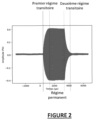
- FIG 2 corresponds to a signal emitted by an ultrasonic transducer 10 excited by an electrical signal at fixed frequency and amplitude.
- the electrical signal is made up of a set of sinusoids, with one and the same frequency, while the ultrasonic signal is made up of a first transient excitation regime (1), a permanent regime (2) and a second transient de-excitation regime (3).
- the regimes (1) and (2) are carried out at a characteristic frequency of the ultrasonic transducer 10, also called 'characteristic frequency' below.
- the characteristic frequency depends on the natural frequency of the transducer 10 and its quality factor.
- the second transient regime (3) presents a sinusoidal signal at the excitation frequency. The difference between the two frequencies of interest is typically a few percent (%).
- the duration of the transient regimes is proportional to the quality factor of the transducer. For example, for a quality factor of 50, 100 cycles are generally necessary to reach steady state (2), which typically corresponds to 1ms for a frequency of around 100 kHz.
- the processing system 100 is advantageously configured to take into account this difference of a few percent (%) and the importance of the transient regime. Indeed, in the particular case of very short ultrasonic signals ( ⁇ 1 ms), the signal is mainly made up of the two transient regimes (1) and (3).
- the frequency of the signal depends on the characteristic frequency of the transducer. It is therefore difficult to produce interference between signals coming from different transducers.
- the coupling device 3 advantageously implements a transformation of the signal into pulses and a thresholding making it possible to be more robust to this frequency dispersion.
- the electrical emission signal from a transducer and the resulting ultrasonic signal can be more complex.
- the limited bandwidth of the ultrasonic transducer 10 means that the ultrasonic signal comprises two transient regimes whose characteristics do not depend only on the emission signal, but also on the specific characteristics of the transducer 10.
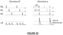
- FIG. 3 illustrates the phase shift as a function of the angle of incidence of the received echo, using three transducers M 0 , M 1 and M 2 .
- the signal arrives with an angle of incidence ⁇ on the set of N transducers (10).
- the difference in distance traveled by the signal to arrive at the transducers M 0 and M 2 , 2d apart, is equal to 2d sin ⁇ .
- the acoustic wave propagates at the speed of sound c.
- the information is contained in the time shift, that is to say in the phase shift of the signal.
- the signals received by the transducers 10 of the ultrasonic sensor 1 are processed by the coupling device 3 and the pulse processing unit 2 to determine the characteristic information(s) relating to an object 5, depending on the application of the 'invention.
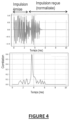
- the characteristic information can for example include information indicating whether an object has been detected or not, or the distance between the sensor 1 and the detected object 5 which can be determined by from the signals received 41 by the transducers 10 by performing a correlation between the received signals and the expected signals (the correlation is maximum for a delay corresponding to the propagation time). It is possible to send an optimized signal whose autocorrelation has low sidelobes to further improve the distance measurement.
- FIG. 4 illustrates the principle of matched filtering correlating the signal emitted by sensor 1 with the signal received by sensor 1.
- the system 100 can be configured to determine characteristic information corresponding to a dynamic characteristic of the object, for example its movement.
- the determination of the characteristic of the object can be carried out by processing several successive static signals, by measuring the distance and the angle for several successive scenes captured by the ultrasonic sensor 1, and by processing such measurements.
- the processing system 100 makes it possible to perform direct, optimized processing by directly providing characteristic information (for example movement from right to left in an application gesture detection), without intermediate information.
- characteristic information for example movement from right to left in an application gesture detection
- the processing system 100 is configured to determine characteristic information (for example detection information such as a direction and distance measurement or gesture detection) using a simplified circuit comprising the coupling device 3 and the processing unit. pulse processing 2.
- characteristic information for example detection information such as a direction and distance measurement or gesture detection
- the signal processing system 100 is configured to process the signals delivered by the ultrasonic transducers 10 of the ultrasonic sensor 1.
- the transducers 10 of the ultrasonic sensor 1 emit signals 40. When these signals reach an object 5, echoes 41 are formed corresponding to the signals reflected 41 by a detected object 5.
- the reflected signals 41 received by N transducers 10 of the ultrasonic sensor 1 are then transmitted to the processing system 100.
- the processing system 100 is configured to process the signals from the N transducers in order to determine at least one characteristic information relating to the detected object 5.
- Each signal from a transducer 10 is received by the coupling device 3 and corresponds to a processing channel in the coupling device 3.
- the coupling device 3 (also called a transformation device) is configured to transform the signals coming from the N transducers 10 of the set of transducers 1 into pulses.
- the pulse processing unit 2 is configured to process the pulses delivered by the coupling device 3 in order to determine at least one characteristic piece of information relating to the detected object.
- the pulse processing unit 2 is configured to determine the characteristic information relating to a detected object 5 from the pulses determined by the coupling device for all the signals coming from the transducers 10.
- the processing system 100 advantageously consumes little energy and ensures coupling between the ultrasonic transducers of the set of transducers 1 and the pulse processing unit 2.
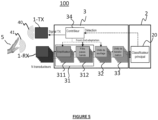
- FIG. 5 represents a system 100 for processing signals from the transducer assembly 1 in which the pulse processing unit 2 comprises a classifier 20 of the pulse neural network type, arranged at the output of the pulse transformation unit 33, according to a first embodiment.
- the impulse neural network 20 is capable of learning on its own an optimal way of adding a delay and combining the different channels associated with the transducers.
- FIG. 5 corresponds to an example of application of the invention to the detection of end-to-end gestures.
- the detection system comprises a set of 1-TX emission transducers comprising a plurality of 10-TX ultrasonic emission transducers configured to emit an ultrasonic signal at a fixed frequency of short duration, such as for example 250 ⁇ s to 100 kHz (acoustic signal).
- a repetition of the measurements can be carried out according to a time interval.
- the time interval can be fixed (for example, a measurement is taken every 10 ms).
- the characteristic information relating to a detected object 5 in the scene of the sensor 1 may include the trajectory of the object.
- the trajectory of the object 5 can then be determined by aggregating the results of the measurements carried out repetitively over a period of time.
- the characteristic information may further include high-level characteristics such as gestures from the determined trajectory.
- the coupling device 3 of the detection system 100 may comprise a pre-processing unit 31 forming a front electronic part ('front-end') comprising a set of amplifiers 311 and/or a set of band-pass filters 312.
- the pre-processing unit 31 is configured to carry out the conversion of the physical signal (charge, voltage, etc.), received from each of the N transducers (10-RX in the example of the figure 5 ) in analog voltage.
- the set of amplifiers 311 comprises at least one amplifier and is configured to amplify the analog voltage thus converted so as to make it more immune to noise likely to be added to the signal.
- the bandpass filter set 312 includes at least one bandpass filter and is configured to filter the voltage (if applicable after amplification by the amplifier set 311) to eliminate out-of-band noise passing.
- the thresholding unit 32 is configured to apply thresholding to the filtered signal delivered by the pre-processing unit 31 (signal derived from the signal coming from each of the N transducers) in order to recover the directional information contained in the phase of the signal filtered using at least one threshold.
- the thresholding unit 32 can be configured to apply thresholding to the signal derived from the signal coming from each of the N transducers of so as to keep only the rising edge of the signal.
- the thresholding unit 32 can be configured to keep only the falling edge or both edges (rising and falling).
- the coupling device 3 thus corresponds to the analog domain, while the pulse processing unit 2 corresponds to the pulse domain and the controller 34 corresponds to a mixed signal domain.
- FIG. 7 illustrates the successive stages of transformation of the signal coming from one of the N transducers (10-RX in the example of the figure 5 ) in pulses containing the phase of the signal while retaining only the rising edge after thresholding, implemented by the coupling device 3, in the example of embodiment of the figure 5 .
- the upper diagram 7A of the Figure 7 represents the signal received from one of the N transducers (10-RX)
- the central diagram 7B of the Figure 7 represents the signal after amplification by the set of amplifiers 311, filtering by the set of bandpass filters 312, and thresholding by the thresholding unit 32.
- the lower diagram 7C of the Figure 7 represents the data obtained after transformation into pulses by the transformation unit 33.
- the coupling device 3 of the processing system 100 may further comprise a controller 34 configured to adapt one or more signal shaping parameters.
- the controller 34 can be configured to adapt the threshold used by the thresholding unit 32 to determine the phase of the signal, according to one or more adaptation criteria such as criteria relating to the distance or the quality of the signal.
- the controller 34 can be configured to adapt the shaping parameters of the signals from the N transducers dynamically or statically.
- the parameter controller 34 may be configured to adapt the threshold used by the thresholding unit 32 based on the distance between the ultrasonic sensor 1 and the detected object 5. For example, the parameter controller 34 can decrease the threshold value during the measurement to adapt it to the decrease in the amplitude of the signal echo with distance.
- the parameter controller 34 can be configured to adapt the value of the threshold according to the quality of previous measurements, calculated in the pulse domain or after real number conversion of the pulse density.
- the threshold used by the thresholding unit 32 to obtain the phase of the signal can be fixed.
- the controller 34 can use information provided by the pulse processing unit 2.
- the pulse processing unit 2 may comprise, in addition to the main classifier, a secondary classifier configured to determine an optimal amplitude for the threshold based on intermediate representations of the information in the transmission chain, in an impulse or non-impulse domain.
- the secondary classifier may determine the threshold magnitude from a set of possible threshold magnitude values.
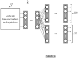
- the secondary classifier may be a secondary spiking neural network (SNN), as illustrated in Figure 1. Figure 8 .
- the coupling device may also comprise at least one coherence detector.
- FIG 8 represents an example of a pulse processing unit 2 comprising a main classifier 20 of the SNN neural network type used to determine the characteristic information relating to a detected object 5, from the pulses received (for example to detect gestures), and a secondary classifier 200, for example of the SNN neural network type, configured to select the threshold to be used by the thresholding unit 32 and transmit the threshold information to the controller 34.
- a main classifier 20 of the SNN neural network type used to determine the characteristic information relating to a detected object 5, from the pulses received (for example to detect gestures)
- a secondary classifier 200 for example of the SNN neural network type, configured to select the threshold to be used by the thresholding unit 32 and transmit the threshold information to the controller 34.
- the controller 34 can further be configured to synchronize the different functional blocks of the processing system 100 in order to implement relevant feedback.
- the controller 34 can in particular be configured to control the moment of sending of the pulses (in transmission) and synchronize the transmission with the reception in order to be able to measure the information of interest (for example the time of flight).
- the controller 34 can further be configured to select a time interval of interest in which echoes from objects located at a chosen distance interval will be received.
- the controller 34 can retrieve information on any functional block, ie on the signal before/after amplification, before/after filtering, before/after thresholding to dynamically adapt detection parameters.
- part of the impulse neural network 20 is dedicated to the choice of an optimal threshold for the measurement per channel.
- the pulse transformation unit 33 is configured to determine a pulse density for each of the N channels corresponding respectively to the N transducers 10 from which the signals processed by the processing system 100 come. The pulse densities thus determined can be used as input to the pulse processing unit 2.
- the pulse processing unit 2 comprises a main classifier 20 (for example, pulse neural network) for determining classification information from the pulses delivered by the coupling device 3, i.e. without having to go through an intermediate representation of the data.
- the characteristic information relating to a detected object 5 includes classification information, for example such as end-to-end gesture classification information in the embodiment. of the figure 5 .
- the non-event classifier takes as input the signal, which can be processed beforehand by a post-filtering block, in the form of a vector per frame .
- the classifier 20 makes a decision on the nature of the gesture based on the frame and the previous frames and potentially the following frames over a certain window.
- FIG. 9 represents a processing system 100, according to a second embodiment.
- the components 31, 32, 33, and 34 of the treatment system 100 are similar to those described with reference to the figure 5 corresponding to the first embodiment.
- the processing system 100 according to the second embodiment differs from the first embodiment, shown in the figure. figure 5 , in that the pulse processing unit 2 comprises, instead of the pulse classifier 20, a set of coherence detectors 21 comprising at least one coherence detector, followed by a unit for determining characteristic information 22.
- the characteristic information determination unit 22 is configured to determine at least one characteristic information relating to an object detected 5 by the ultrasonic sensor 1 (for example distance and/or direction of the echo(es) coming from different objects in the scene captured by the ultrasonic sensor 1).
- the set of coherence detectors 21 exploits the directions of incidence of the echoes coming from the different objects in the scene captured by the ultrasound sensor 1.
- the set of coherence detectors 21 is configured to provide in parallel coherence information for M directions from the N channels corresponding respectively to the N transducers.
- the output of a coherence detector 21 has a certain pulse density at a time t depending on whether the signals received in this direction are coherent.
- the set of coherence detectors 21 thus detect whether the signals received in a direction are or not consistent.
- a coherence detector 21 may comprise a leaky integrator LIF for measuring the alignment of the edges of the signals corresponding to the N respective channels corresponding to the N transducers.
- a leak integrator ascronym for “Leaky Integrator and Fire”
- the LIF output y n takes the value 1, which means that coherence is detected between the signals corresponding to the N channels for a given direction.
- LIF can also be performed in continuous time with an analog implementation, following a similar operating principle. Equation (3) is then replaced by a time-function equation instead of being a recurrence equation.
- the set of coherence detectors 21 has the advantage of being able to operate even if the different signals to be compared (signals corresponding to the N channels) have different amplitudes, which is the case if the signal is in transient mode or if the transducers 10 are different from each other. Such coherence detection processing is therefore robust to a certain technological variability.
- the set of coherence detectors 21 operates even if the signals do not have exactly the same frequency, for example in transient conditions.
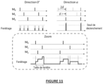
- the set of coherence detectors 21 may comprise a windowing unit configured to apply windowing, instead of a LIF to detect the coherence between the signals from the received pulses.
- Coherence detection by windowing consists of counting the number of pulses, among all the N input channels contained, in a small width window. Similar to the embodiment in which the coherence detectors use a LIF, a coherence threshold can be used to detect coherence between the signals corresponding to the N channels for a given direction. The coherence threshold is then applied to the number of pulses detected in the window which starts with the first pulse.
- FIG. 11 illustrates a coherence detection implemented by the coherence detector assembly 21 using windowing, according to such an embodiment.
- a window is applied to the detection of each rising edge.
- the coherence detector assembly 21 provides an output in the form of a plurality of series of pulses.
- the pulses can be directly supplied to a pulse-type classifier 20 (SNN). If the classifier 20 is a non-event classifier type classifier, the pulses are converted into pulse density before being transmitted to the classifier 20.
- the conversion can be carried out using a post-processing block comprising a pass filter. low or a counter to count the number of pulses per time interval (for example 10 ms). The greater the density of the pulses determined by the coupling device 2 at a given instant, the more coherence there is in the signals coming from the transducers 10 of the ultrasonic sensor 1.
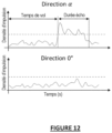
- the characteristic information determination unit 22 may be configured to determine the direction of the main echo(es) from the output of the coherence detector, as shown in FIG. Figure 12 .
- FIG. 12 illustrates the density of the pulses delivered by the set of coherence detectors 21 as a function of time, in an echo direction(s) of angle ⁇ (upper diagram), and in an echo direction(s) of angle 0° (bottom diagram). There Figure 12 highlights flight time for distance measurement.
- An echo coming from a particular direction results in a stronger pulse density on the output corresponding to the direction of the echo than on the outputs corresponding to the other possible directions.
- the direction(s) of arrival of the echoes can be determined.
- FIG. 12 also illustrates the principle of distance measurement. Using the same information as for the direction, the distance measurement can be carried out at the output of the set of coherence detectors 21 by applying a pulse density threshold to the pulse density, and by calculating the distance in using equation (1).
- FIG 13 represents a processing system 100, according to a third embodiment.
- the processing system 100 according to the third embodiment is similar to the processing system, according to the second embodiment shown on the Figure 9 , and similarly uses a set of coherence detectors 21. However, it also uses a classifier 20 of the impulse neural network type configured to provide classification information from the pulses delivered by the set of coherence detectors. Such a classifier 20 is configured to receive the series of pulses delivered by the coherence detector assembly 21.
- the characteristic information determination unit 22 of the detection system 100 according to the second embodiment ( Figure 9 ) is thus replaced in the third embodiment by the classifier 20.
- FIG. 14 represents a processing system 100, according to a fourth embodiment.
- the processing system 100 according to the fourth embodiment is similar to the processing system, according to the third embodiment shown on the Figure 9 , and also uses a set of coherence detectors 21. However, it additionally uses a classifier 20 of the non-event classifier type, configured to provide classification information from the pulses delivered by the set of coherence detectors 21, preceded by a post-processing block 23.
- the post-processing block 23 is configured to convert the pulses into pulse density before being transmitted to the non-event classifier 20.
- the post-processing block 23 may include a low-pass filter at the output of the coherence detector assembly 21 to provide an image of the pulse density, rather than a series of pulses, and a sampling unit to sample the low-frequency signal provided at the output of the low-pass filter to carry out data processing.
- the post-processing block 23 may include an asynchronous counter arranged at the output of the set of coherence detectors 21 to count the pulses and sample the output of the set of coherence detectors with a clock signal.
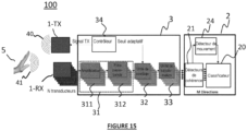
- FIG. 15 represents a processing system 100, according to a fifth embodiment.
- the processing system 100 according to the fifth embodiment is similar to the processing system of the third embodiment shown in the Figure 13 , and uses in an identical manner a set of coherence detectors 21.
- This fifth embodiment corresponds to an application of the invention to gesture detection.
- the processing system 100 according to the fifth embodiment further comprises a motion detector 24 to optimize consumption.
- the processing system 100 according to the fifth embodiment is in particular configured to be activated only when a movement is detected by the movement detector 24. This makes it possible to avoid activating gesture detection in the absence of movement. In fact, the most of the time, there is no movement in front of sensor 1 in the area of interest (scene observed by sensor 1) so that it is not necessary in this case to determine which gesture was performed .
- the classifier 20 can be arranged directly on the output of the pulse transformation unit 33 or at the output of the set of coherence detectors 21, as shown in the Figure 15 . In the example of the Figure 15 , the classifier 20 can then perform a classification to detect a gesture only when a movement is detected by the motion detector.
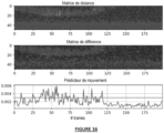
- the output of the set of coherence detectors 21 can be represented by a matrix B of dimensions T ⁇ N ⁇ K with T the number of measurements or frames, N the number of samples per frame (time axis on the Figure 12 ), and K the number of directions analyzed in the set of coherence detectors 21.
- the elements of matrix B are denoted b i,j,k .
- the number of directions K is less than or equal to the total number of directions M.
- the elements of matrix B correspond to the pulse density in an interval [t, t+t frame ] with t frame designating the length of a frame.
- the motion detector 24 then uses the elements of the matrix B.
- Motion can be quantified by examining the difference between two successive frames on the distance matrix.
- FIG. 16 illustrates the calculation of a motion predictor on real data (distance matrix, frame-by-frame differentiation and motion detection). In the example of the Figure 16 , it can be observed on the distance matrix a movement from frame 0 to 120, then no movement thereafter. By comparing the motion predictor with a threshold, a signal is obtained which can be used by the gesture detector 25 to determine a gesture classification.
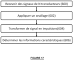
- FIG. 17 illustrates the method of processing signals from a set of transducers, according to certain embodiments.
- step 600 at least some of the transducers of the set of transducers emit signals and/or receive echoes corresponding to the reflection of the signals by a detected object 5.
- steps 602 and 604 a step of transforming the signals received from at least certain transducers of the set of transducers into pulses is implemented.
- step 602 for each signal received by one of the N transducers 10, thresholding is applied to a signal derived from the signal received from the transducer so as to extract directional information contained in the phase of the derived signal, using at least one threshold, the extracted information comprising the rising and/or falling edges of the derived signal.
- step 604 the signal derived from the signal received from the transducer is transformed into pulses containing the phase of the signal, using the signal edge(s) extracted in the step of applying thresholding.
- step 606 a step of processing the pulses obtained is implemented, the step of processing the pulses comprising the determination of the characteristic information from the pulses determined for all the signals received from the transducers.
- the determined characteristic information can then be delivered for additional processing, or to generate a display of this information. Alternatively, an action can be triggered based on the determined characteristic information.
- the embodiments of the invention make it possible to detect objects, gestures or even dynamic characteristics of objects.
- the set of transducers 1 can be a 2D matrix.
- Each transducer 10 of the set of transducers 1 sends a pulse, which is returned if the transducer 10 is located facing a “hollow” of the hand, and which is transmitted if the transducer is located facing the skin.
- the set of returned pulses is used to form an image (at what level of the processing chain?), which is then processed by the processing system 100.
- the embodiments of the invention thus allow direct coupling of the ultrasonic transducers 10 to a pulse processing unit 2 (comprising for example a neural network) making it possible to directly determine the characteristic information(s), depending on the application of the invention.
- the processing system 100 is advantageously configured to improve the angular resolution compared to the ultrasonic transducer systems of the state of the art.
- the processing system 100 is configured to make it possible to reduce the blind zone of the transducer system, to reduce the complexity of the processing, and to provide robustness to the dispersion in characteristic of the transducers 10 of the set of transducers 1, while having a certain compactness (all of the transducers 10 are located in the same place) and providing quality angular information.
- processing device 100 or subsystems of the device can be implemented in various ways by hardware, software, or a combination of hardware and software, especially in the form of program code capable of being distributed as a program product, in various forms.
- program code may be distributed using computer-readable media, which may include computer-readable storage media and communications media.
- the methods described in the present description may in particular be implemented in the form of computer program instructions executable by one or more processors in a computer computing device. These Computer program instructions may also be stored in computer-readable media.
- the processing system 100 can be used to provide images obtained by ultrasound representing the echoes received by a set of ultrasound transducers. In certain cases, not only the first echo, but also the following echoes can be represented. Image processing makes it possible to extract the detection information defined according to the biomedical application (for example, neck thickness). The information provided can then be used to assist in medical diagnosis.
- the embodiments make it possible to simplify image reconstruction processing of ultrasound systems outside laboratories.
Description
L'invention concerne de manière générale le domaine des systèmes de détection et en particulier un dispositif et un procédé de traitement du signal issus d'un ensemble de transducteurs ultrasons.The invention generally relates to the field of detection systems and in particular to a device and a method for processing the signal from a set of ultrasonic transducers.
Les capteurs ultrasonores sont aujourd'hui utilisés dans de nombreuses applications telles que la localisation dans l'espace, la détection de geste, la reconnaissance d'empreinte, les images biomédicales, etc.Ultrasonic sensors are today used in many applications such as spatial localization, gesture detection, fingerprint recognition, biomedical images, etc.
Un capteur à ultrasons émet à intervalles réguliers de courtes impulsions sonores à haute fréquence. Ces impulsions se propagent dans l'air à la vitesse du son. Lorsqu'elles rencontrent un objet, elles se réfléchissent et reviennent sous forme d'écho au capteur. Celui-ci calcule alors la distance le séparant de la cible sur la base du temps écoulé entre l'émission du signal et la réception de l'écho. Un capteur à ultrasons émet à intervalles réguliers de courtes impulsions sonores à haute fréquence. Ces impulsions se propagent dans l'air à la vitesse du son. Lorsqu'elles rencontrent un objet, elles se réfléchissent et reviennent sous forme d'écho au capteur. Celui-ci calcule alors la distance le séparant de la cible sur la base du temps écoulé entre l'émission du signal et la réception de l'écho. Un capteur à ultrasons émet à intervalles réguliers de courtes impulsions sonores à haute fréquence. Ces impulsions se propagent dans l'air à la vitesse du son. Lorsqu'elles rencontrent un objet, elles se réfléchissent et reviennent sous forme d'écho au capteur. Celui-ci calcule alors la distance le séparant de la cible sur la base du temps écoulé entre l'émission du signal et la réception de l'écho. Un capteur ultrasonore émet à intervalles réguliers ou en permanence de courts signaux ultrasonores à haute fréquence. Ces impulsions se propagent dans l'air à la vitesse du son. Lorsqu'elles rencontrent un objet, elles se réfléchissent et reviennent sous forme d'écho sur le capteur qui peut alors calculer la distance qui le sépare de l'objet, en utilisant le temps écoulé entre l'émission du signal et la réception de l'écho par le capteur.An ultrasonic sensor emits short, high-frequency sound pulses at regular intervals. These pulses travel through the air at the speed of sound. When they encounter an object, they are reflected and return as an echo to the sensor. This then calculates the distance separating it from the target based on the time elapsed between the transmission of the signal and the reception of the echo. An ultrasonic sensor emits short, high-frequency sound pulses at regular intervals. These pulses travel through the air at the speed of sound. When they encounter an object, they are reflected and return as an echo to the sensor. This then calculates the distance separating it from the target based on the time elapsed between the transmission of the signal and the reception of the echo. An ultrasonic sensor emits short, high-frequency sound pulses at regular intervals. These pulses travel through the air at the speed of sound. When they encounter an object, they are reflected and return as an echo to the sensor. This then calculates the distance separating it from the target based on the time elapsed between the transmission of the signal and the reception of the echo. An ultrasonic sensor emits short, high-frequency ultrasonic signals at regular intervals or continuously. These pulses travel through the air at the speed of sound. When they encounter an object, they are reflected and return as an echo to the sensor which can then calculate the distance which separates it from the object, using the time elapsed between the emission of the signal and the reception of the signal. echo from the sensor.
L'utilisation de capteurs ultrasonores requiert souvent un traitement du signal proche capteur relativement lourd pour en extraire les informations pertinentes, selon l'application, telles que par exemple la distance et l'angle pour la localisation d'objet, le type de mouvements pour la détection de geste, des informations de validation dans le cas de reconnaissance d'empreinte, des informations de diagnostic dans le cas d'une image biomédicale.The use of ultrasonic sensors often requires relatively heavy near-sensor signal processing to extract relevant information, depending on the application, such as for example the distance and angle for object localization, the type of movements for gesture detection, validation information in the case of fingerprint recognition, diagnostic information in the case of a biomedical image.
Différentes solutions de détection de geste ont été proposées telles que des solutions par mesure par temps de vol, comme décrit par exemple dans :
-
R. Nandakumar, V. lyer, D. Tan, and S. Gollakota, "FingerIO: Using Active Sonar for Fine-Grained Finger Tracking," in Proceedings of the 2016 CHI Conférence on Human Factors in Computing Systems, New York, NY, USA, May 2016, pp. 1515-1525, doi: 10.1145/2858036.2858580 -
A. Das, I. Tashev, and S. Mohammed, "Ultrasound based gesture récognition," in 2017 IEEE International Conférence on Acoustics, Speech and Signal Processing (ICASSP), Mar. 2017, pp. 406-410, doi: 10.1109/ICASSP.2017.7952187 -
K. Ling, H. Dai, Y. Liu, and A. X. Liu, "UltraGesture: Fine-Grained Gesture Sensing and Récognition," in 2018 15th Annual IEEE International Conférence on Sensing, Communication, and Networking (SECON), Jun. 2018, pp. 1-9, doi: 10.1109/SAHCN.2018.8397099
-
R. Nandakumar, V. lyer, D. Tan, and S. Gollakota, "FingerIO: Using Active Sonar for Fine-Grained Finger Tracking," in Proceedings of the 2016 CHI Conference on Human Factors in Computing Systems, New York, NY, USA, May 2016, pp. 1515-1525, doi: 10.1145/2858036.2858580 -
A. Das, I. Tashev, and S. Mohammed, "Ultrasound based gesture recognition," in 2017 IEEE International Conference on Acoustics, Speech and Signal Processing (ICASSP), Mar. 2017, pp. 406-410, doi: 10.1109/ICASSP.2017.7952187 -
K. Ling, H. Dai, Y. Liu, and AX Liu, "UltraGesture: Fine-Grained Gesture Sensing and Recognition," in 2018 15th Annual IEEE International Conference on Sensing, Communication, and Networking (SECON), Jun. 2018, p. 1-9, doi: 10.1109/SAHCN.2018.8397099
D'autres solutions de détection de geste, basées sur des mesures par Doppler, ont été proposées, comme décrit par exemple dans :
-
W. Wang, A. X. Liu, and K. Sun, "Device-free gesture tracking using acoustic signais," in Proceedings of the 22nd Annual International Conférence on Mobile Computing and Networking, New York, NY, USA, Oct. 2016, pp. 82-94, doi: 10.1145/2973750.2973764 -
S. Yun, Y.-C. Chen, and L. Qiu, "Turning a Mobile Device into a Mouse in the Air," in Proceedings of the 13th Annual International Conférence on Mobile Systems, Applications, and Services, New York, NY, USA, May 2015, pp. 15-29, doi: 10.1145/2742647.2742662 -
X. Li, H. Dai, L. Cui, and Y. Wang, "SonicOperator: Ultrasonic gesture recognition with deep neural network on mobiles," in 2017 IEEE SmartWorld, Ubiquitous Intelligence Computing, Advanced Trusted Computed, Scalable Computing Communications, Cloud Big Data Computing, Internet of People and Smart City Innovation (SmartWorld/SCALCOM/UIC/ATC/CBDCom/IOP/SCI), Aug. 2017, pp. 1-7, doi: 10.1109/UIC-ATC.2017.8397483 -
E. A. Ibrahim, M. Geilen, J. Huisken, M. Li, and J. P. de Gyvez, "Low Complexity Multi-directional In-Air Ultrasonic Gesture Recognition Using a TCN," in 2020 Design, Automation Test in Europe Conférence Exhibition (DATE), Mar. 2020, pp. 1259-1264, doi: 10.23919/DATE48585.2020.9116482
-
W. Wang, AX Liu, and K. Sun, "Device-free gesture tracking using acoustic signals," in Proceedings of the 22nd Annual International Conference on Mobile Computing and Networking, New York, NY, USA, Oct. 2016, pp. 82-94, doi: 10.1145/2973750.2973764 -
S. Yun, Y.-C. Chen, and L. Qiu, "Turning a Mobile Device into a Mouse in the Air," in Proceedings of the 13th Annual International Conference on Mobile Systems, Applications, and Services, New York, NY, USA, May 2015, pp. 15-29, doi: 10.1145/2742647.2742662 -
Li Data Computing, Internet of People and Smart City Innovation (SmartWorld/SCALCOM/UIC/ATC/CBDCom/IOP/SCI), Aug. 2017, p. 1-7, doi: 10.1109/UIC-ATC.2017.8397483 -
EA Ibrahim, M. Geilen, J. Huisken, M. Li, and JP de Gyvez, "Low Complexity Multi-directional In-Air Ultrasonic Gesture Recognition Using a TCN," in 2020 Design, Automation Test in Europe Conference Exhibition (DATE) , Mar. 2020, pp. 1259-1264, doi: 10.23919/DATE48585.2020.9116482
Les capteurs ultrasonores existants présentent cependant des architectures complexes et sont soumis à de fortes contraintes en termes de dimensionnement des composants (bruit, distorsion). En outre, ils mettent généralement en oeuvre des étapes de traitement du signal complexes, telles qu'une étape de transformation de Fourier rapide FFT (acronyme pour « Fast Fourier Transform »), une étape de corrélation, une étape de filtrage non-linéaire, etc. Il en résulte un temps de calcul computationnel, une consommation et un temps de calcul très importants. Par ailleurs, les capteurs ultrasonores existants doivent stocker des représentations intermédiaires du signal, ce qui augmente les ressources matérielles nécessaires.Existing ultrasonic sensors, however, have complex architectures and are subject to strong constraints in terms of component sizing (noise, distortion). In addition, they generally implement complex signal processing steps, such as a fast Fourier transform step FFT (acronym for “Fast Fourier Transform”), a correlation step, a non-linear filtering step, etc. This results in very significant computational time, consumption and calculation time. Furthermore, existing ultrasonic sensors must store intermediate representations of the signal, which increases the hardware resources required.
La modalité ultrasonore des transducteurs ultrasonores pour la mesure de temps de vol n'est pas sensible aux mêmes objets que d'autres modalités (RADAR, optique) (par exemple, une onde ultrasonore sera réfléchie par une vitre transparente).The ultrasonic modality of ultrasonic transducers for time-of-flight measurement is not sensitive to the same objects as other modalities (RADAR, optical) (for example, an ultrasonic wave will be reflected by a transparent window).
Par ailleurs, le signal ultrasonore d'un transducteur ultrasonore unique est en général très peu directif, l'onde ultrasonore étant émise ou reçue dans un cône d'émission avec un angle de typiquement plusieurs dizaines de degrés. Il s'ensuit que le traitement du signal émis fournit une localisation d'objet avec une grande incertitude angulaire lorsqu'un capteur ultrasonore est utilisé.Furthermore, the ultrasonic signal from a single ultrasonic transducer is generally very non-directive, the ultrasonic wave being emitted or received in an emission cone with an angle of typically several tens of degrees. It follows that the processing of the transmitted signal provides object localization with large angular uncertainty when an ultrasonic sensor is used.
Pour améliorer la résolution angulaire des systèmes de transducteurs ultrasons, il a été proposé d'utiliser des techniques de triangulation et de formations de faisceaux (« beamforming »). Les méthodes de triangulation consistent à mesurer la distance à partir de deux emplacements distincts (ou plus). Le recoupement des deux (ou plus) informations permet de localiser un objet avec une précision améliorée. Cependant, pour être efficace, les deux couples sources/détecteurs doivent être bien espacés l'un de l'autre, ce qui n'est pas toujours possible ou souhaitable en pratique, et peut poser des difficultés d'intégration.To improve the angular resolution of ultrasound transducer systems, it has been proposed to use triangulation and beamforming techniques. Triangulation methods involve measuring distance from two (or more) distinct locations. The cross-checking of the two (or more) pieces of information makes it possible to locate an object with improved precision. However, to be effective, the two source/detector pairs must be well spaced from each other, which is not always possible or desirable in practice, and can pose difficulties. integration.
L'approche de beamsteering/beamforming désigne un ensemble de techniques complexes qui permettent respectivement d'ajuster les caractéristiques du faisceau ultrasonore en émission (« beamsteering »), ou d'améliorer la qualité des informations mesurées en réception (« beamforming »). Un tel ensemble de techniques repose sur la construction d'interférences entre les signaux d'un ensemble de transducteurs qui envoie/mesure le signal avec un déphasage temporel, qui correspond à l'angle de réception/d'émission de l'onde plane.The beamsteering/beamforming approach refers to a set of complex techniques which respectively allow the characteristics of the ultrasound beam to be adjusted in transmission (“beamsteering”), or to improve the quality of information measured in reception (“beamforming”). Such a set of techniques relies on the construction of interference between the signals of a set of transducers which sends/measures the signal with a temporal phase shift, which corresponds to the reception/transmission angle of the plane wave.
Dans le cas de technique classique de type « beamsteering », les différents transducteurs de l'ensemble de transducteurs ultrasonores émettent des signaux avec un déphasage temporel de manière à ce que les ondes acoustiques générées par les différents transducteurs soient constructives, dans au moins une direction particulière, et destructives dans les autres directions. Plusieurs émissions avec des déphasages différents sont généralement utilisées. La mesure des échos correspondant à ces différentes émissions permet d'améliorer la résolution angulaire. Dans le cas du « beamforming », une seule mesure en réception de l'ensemble de transducteurs peut donner lieu à différents traitements du signal, correspondant à différentes manières d'interférer, chacun correspondant à une direction d'observation. Il est alors possible de déterminer la position angulaire de l'objet. Contrairement à la triangulation, les techniques de « beamforming » imposent que les différents transducteurs soient localisés de manière très proches, avec une distance entre les transducteurs inférieure à une demi-longueur d'onde du signal. A défaut, le système présente des artefacts, c'est-à-dire une émission/sensibilité non souhaitée dans certaines directions. De tels artefacts dégradent largement les performances du système (présence de lobes de réseau dans le diagramme de directivité du capteur ultrason, en raison du repliement de spectre spatial ou « spatial aliasing »).In the case of conventional “beamsteering” type technique, the different transducers of the set of ultrasonic transducers emit signals with a time phase shift so that the acoustic waves generated by the different transducers are constructive, in at least one direction. particular, and destructive in other directions. Several emissions with different phase shifts are generally used. Measuring the echoes corresponding to these different emissions makes it possible to improve the angular resolution. In the case of “beamforming”, a single measurement in reception of the set of transducers can give rise to different processing of the signal, corresponding to different ways of interfering, each corresponding to a direction of observation. It is then possible to determine the angular position of the object. Unlike triangulation, beamforming techniques require the different transducers to be located very close together, with a distance between the transducers less than half a wavelength of the signal. Otherwise, the system presents artifacts, that is to say unwanted emission/sensitivity in certain directions. Such artifacts greatly degrade the performance of the system (presence of grating lobes in the directivity diagram of the ultrasound sensor, due to spatial aliasing or “spatial aliasing”).
Dans la mesure où un tel principe de mesure repose sur des interférences entre signaux, il est important que les différents signaux soient à la même fréquence. En pratique, du fait de l'inhomogénéité des fréquences caractéristiques des transducteurs ultrasonores d'un même ensemble de transducteurs, les systèmes ultrasons, en particulier ceux qui mettent en place des techniques de beamforming, utilisent des signaux contenant principalement un régime permanent assez long, car la fréquence du signal en régime permanent ne dépend pas de la fréquence caractéristique du transducteur, et le rapport signal/bruit est plus favorable en régime permanent. De plus, un signal long permet d'améliorer les performances de filtres adaptés (« matched-filter ») classiquement utilisés. Cependant, dans le cas où l'émission et la réception sont réalisés par le (ou les) même(s) transducteur(s), les deux opérations ne peuvent être réalisées en même temps de sorte que le système est « aveugle » pendant la durée de l'émission. Lorsqu'émission et réception sont réalisées par des transducteurs différents, le système est en général également aveugle, car le signal d'émission peut parasiter le signal de réception via un couplage mécanique ou électrique, à moins d'un découplage complexe à mettre en oeuvre. La « zone aveugle » du composant correspond typiquement à une durée de propagation d'environ 1 ms. Dans l'air (célérité du son = 300 m/s), cela correspond à une distance aller-retour de quelques dizaines de centimètres. Par conséquent, il est difficile d'employer les techniques de « beamforming » pour mesurer des distances inférieures à cette distance.Since such a measurement principle relies on interference between signals, it is important that the different signals are at the same frequency. In practice, due to the inhomogeneity of the characteristic frequencies of the ultrasonic transducers of the same set of transducers, ultrasound systems, in particular those which implement beamforming techniques, use signals mainly containing a fairly long steady state, because the frequency of the signal in steady state does not depend on the characteristic frequency of the transducer, and the signal-to-noise ratio is more favorable in steady state. In addition, a long signal makes it possible to improve the performance of conventionally used matched filters. However, in the case where transmission and reception are carried out by the same transducer(s), the two operations cannot be carried out at the same time so that the system is "blind" during the duration of the broadcast. When transmitting and receiving are produced by different transducers, the system is generally also blind, because the transmission signal can interfere with the reception signal via mechanical or electrical coupling, unless complex decoupling is required. The “blind zone” of the component typically corresponds to a propagation time of approximately 1 ms. In the air (speed of sound = 300 m/s), this corresponds to a round trip distance of a few tens of centimeters. Therefore, it is difficult to use beamforming techniques to measure distances smaller than this distance.
Un autre inconvénient du « beamforming » réside dans la lourdeur des traitements qu'il met en oeuvre, en particulier lorsque de tels traitements doivent être embarqués ou réalisés en temps réel.Another disadvantage of “beamforming” lies in the cumbersome processing that it implements, in particular when such processing must be on-board or carried out in real time.
Il existe donc un besoin pour un dispositif et un procédé de traitement du signal issus d'un ensemble de transducteurs ultrasons améliorés.There is therefore a need for a device and a method for processing the signal from a set of improved ultrasound transducers.
À cet effet, il est proposé un système de traitement de signaux délivrés par un capteur ultrasonore, le capteur ultrasonore comprenant un ensemble de transducteurs, au moins certains des transducteurs de l'ensemble de transducteurs étant configurés pour émettre des signaux et/ou recevoir des échos correspondant à la réflexion des signaux par un objet détecté, des signaux étant transmis par une pluralité de transducteurs du capteur ultrasonore au système de traitement en réponse à la réception d'échos par lesdits transducteurs, le système de traitement étant configuré pour déterminer au moins une information caractéristique relative à l'objet détecté, à partir des signaux reçus des transducteurs du capteur ultrasonore. Avantageusement, le système de traitement comprend un dispositif de couplage configuré pour transformer les signaux reçus d'au moins certains transducteurs de l'ensemble de transducteurs en impulsions, et une unité de traitement d'impulsions configurée pour traiter les impulsions délivrées par le dispositif de couplage.For this purpose, a system is proposed for processing signals delivered by an ultrasonic sensor, the ultrasonic sensor comprising a set of transducers, at least some of the transducers of the set of transducers being configured to emit signals and/or receive signals. echoes corresponding to the reflection of signals by a detected object, signals being transmitted by a plurality of transducers of the ultrasonic sensor to the processing system in response to the reception of echoes by said transducers, the processing system being configured to determine at least characteristic information relating to the detected object, from the signals received from the transducers of the ultrasonic sensor. Advantageously, the processing system comprises a coupling device configured to transform the signals received from at least certain transducers of the set of transducers into pulses, and a pulse processing unit configured to process the pulses delivered by the processing device. coupling.
Le dispositif de couplage comprend :
- une unité de seuillage configurée pour appliquer, pour chaque signal reçu d'un transducteur, un seuillage à un signal dérivé dudit signal reçu du transducteur de manière à extraire une information directionnelle contenue dans la phase du signal dérivé, en utilisant au moins un seuil, l'information extraite comprenant les fronts montants et/ou descendants du signal dérivé ;
- une unité de transformation de signal en impulsions configurée pour transformer le signal dérivé du signal reçu du transducteur en des impulsions contenant la phase du signal, en utilisant le ou les fronts du signal extraits par l'unité de seuillage.
- a thresholding unit configured to apply, for each signal received from a transducer, thresholding to a signal derived from said signal received from the transducer so as to extract directional information contained in the phase of the derived signal, using at least one threshold, the extracted information comprising the rising and/or falling edges of the derived signal;
- a pulse signal transformation unit configured to transform the signal derived from the signal received from the transducer into pulses containing the phase of the signal, using the signal edge(s) extracted by the thresholding unit.
L'unité de traitement d'impulsions est configurée pour déterminer au moins une information caractéristique relative à l'objet détecté à partir des impulsions déterminées par le dispositif de couplage pour tous les signaux reçus des transducteurs.The pulse processing unit is configured to determine at least one characteristic information relating to the detected object from the pulses determined by the coupling device for all the signals received from the transducers.
Dans un mode de réalisation, l'unité de traitement d'impulsions comprend au moins un classificateur.In one embodiment, the pulse processing unit comprises at least one classifier.
Dans un mode de réalisation, ledit au moins un classificateur peut comprendre un classificateur principal, le classificateur principal étant un classificateur de type réseau de neurones impulsionnel ou classificateur non-évènementiel.In one embodiment, said at least one classifier may comprise a main classifier, the main classifier being an impulse neural network type classifier or non-event classifier.
Dans un mode de réalisation, ledit au moins un classificateur peut comprendre en outre un classificateur secondaire pour déterminer l'amplitude du seuil utilisé par l'unité de seuillage parmi un ensemble de valeurs possibles d'amplitudes de seuil à partir des impulsions reçues du dispositif de couplage.In one embodiment, said at least one classifier may further comprise a secondary classifier for determining the amplitude of the threshold used by the thresholding unit from a set of possible values of threshold amplitudes from the pulses received from the device coupling.
Dans un mode de réalisation, le système de traitement peut en outre comprendre un ensemble d'amplificateurs, l'ensemble d'amplificateurs comprenant au moins un amplificateur et étant configuré pour amplifier la tension analogique de chaque signal reçu du transducteur.In one embodiment, the processing system may further include a set of amplifiers, the set of amplifiers comprising at least one amplifier and being configured to amplify the analog voltage of each signal received from the transducer.
Le système de traitement peut en outre comprendre un ensemble de filtres passe-bande, l'ensemble de filtres passe-bande comprenant au moins un filtre passe-bande et étant configuré pour filtrer la tension amplifiée par l'ensemble d'amplificateurs de manière à éliminer le bruit en dehors de la bande passante, le signal dérivé de chaque signal reçu du transducteur étant le signal délivré par l'ensemble de filtres passe-bande.The processing system may further include a set of bandpass filters, the set of bandpass filters comprising at least one bandpass filter and configured to filter the voltage amplified by the set of amplifiers so as to eliminate noise outside the pass band, the signal derived from each signal received from the transducer being the signal delivered by the set of band pass filters.
Dans des modes de réalisation, le système de traitement peut comprendre un contrôleur configuré pour adapter un ou plusieurs paramètres de mise en forme des signaux reçus des transducteurs en fonction d'un ou plusieurs critères d'adaptation en utilisant des signaux provenant de l'unité de traitement d'impulsions.In embodiments, the processing system may include a controller configured to adapt one or more shaping parameters of signals received from the transducers based on one or more adaptation criteria using signals from the unit pulse processing.
En particulier, le contrôleur peut être configuré pour adapter le seuil utilisé par l'unité de seuillage en fonction de la distance entre le capteur ultrasonore et l'objet, ou en fonction de la qualité de mesures précédentes effectuées par le capteur ultrasonore, la qualité étant calculée dans le domaine des impulsions ou après une conversion en nombre réel de la densité des impulsions.In particular, the controller can be configured to adapt the threshold used by the thresholding unit as a function of the distance between the ultrasonic sensor and the object, or as a function of the quality of previous measurements carried out by the ultrasonic sensor, the quality being calculated in the pulse domain or after a real number conversion of the pulse density.
Dans un mode de réalisation, l'unité de traitement d'impulsions peut comprendre un ensemble de détecteurs de cohérence comprenant au moins un détecteur de cohérence et une unité de détermination d'informations caractéristiques, l'ensemble des détecteurs de cohérence étant configuré pour détecter si les signaux provenant des transducteurs, pour une direction donnée des échos provenant de l'objet, sont cohérents à partir des impulsions délivrées par l'unité de transformation en impulsions, et pour délivrer lesdites impulsions à l'unité de détermination d'informations caractéristiques si une cohérence est détectée.In one embodiment, the pulse processing unit may comprise a set of coherence detectors comprising at least one coherence detector and a unit for determining characteristic information, all of the coherence detectors being configured to detect if the signals coming from the transducers, for a given direction of the echoes coming from the object, are coherent from the pulses delivered by the pulse transformation unit, and to deliver said pulses to the characteristic information determination unit if consistency is detected.
L'unité de détermination des informations caractéristiques peut être une unité de mesure de la distance et/ou la direction des échos provenant de l'objet.The unit for determining the characteristic information may be a unit for measuring the distance and/or the direction of the echoes coming from the object.
Dans un mode de réalisation l'unité de détermination des informations caractéristiques peut être un classificateur.In one embodiment the unit for determining the characteristic information may be a classifier.
Dans un mode de réalisation, un détecteur de cohérence peut comprendre un intégrateur de fuite pour mesurer un alignement des fronts des signaux reçus des transducteurs de l'ensemble de transducteurs.In one embodiment, a coherence detector may include a leakage integrator for measuring an alignment of the edges of the signals received from the transducers of the set of transducers.
Un détecteur de cohérence peut comprendre une unité de fenêtrage configurée pour appliquer un fenêtrage pour détecter une cohérence entre les signaux reçus des transducteurs à partir des impulsions délivrées par le dispositif de couplage, l'unité de fenêtrage étant configurée pour décompter le nombre d'impulsions, parmi tous les canaux de transmission correspondant aux différents transducteurs de l'ensemble de transducteurs, dans une fenêtre de largeur donnée.A coherence detector may include a windowing unit configured to apply windowing to detect coherence between the signals received from the transducers from the pulses delivered by the coupling device, the windowing unit being configured to count down the number of pulses , among all the transmission channels corresponding to the different transducers of the set of transducers, in a window of given width.
Dans des modes de réalisation, le système de traitement peut comprendre en outre un filtre passe-bas en sortie de l'ensemble de détecteurs de cohérence configurés pour fournir une image de la densité des impulsions délivrées par l'ensemble de détecteurs de cohérence et une unité d'échantillonnage configurée pour échantillonner le signal à basse-fréquence reçu du filtre passe-bas.In embodiments, the processing system may further comprise a low-pass filter at the output of the set of coherence detectors configured to provide an image of the density of the pulses delivered by the set of coherence detectors and a sampling unit configured to sample the low-frequency signal received from the low-pass filter.
Le système de traitement peut comprendre en outre un compteur asynchrone agencé en sortie de l'ensemble de détecteurs de cohérence configuré pour décompter les impulsions et échantillonner la sortie de l'ensemble de détecteurs de cohérence avec un signal d'horloge.The processing system may further comprise an asynchronous counter arranged at the output of the set of coherence detectors configured to count the pulses and sample the output of the set of coherence detectors with a clock signal.
Dans un mode de réalisation, le système de traitement peut comprendre en outre un détecteur de mouvement agencé en sortie de l'ensemble de détecteurs de cohérence pour détecter la présence de mouvement dans la zone surveillée par le capteur ultrasonore.In one embodiment, the processing system may further comprise a motion detector arranged at the output of the set of coherence detectors to detect the presence of movement in the area monitored by the ultrasonic sensor.
Il est en outre fournit un procédé de traitement de signaux délivrés par un capteur ultrasonore, le capteur ultrasonore comprenant un ensemble de transducteurs, au moins certains des transducteurs de l'ensemble de transducteurs émettant des signaux et/ou recevant des échos correspondant à la réflexion des signaux par un objet détecté, le procédé comprenant la détermination d'au moins une information caractéristique relative à l'objet détecté, à partir des signaux reçus des transducteurs du capteur ultrasonore. Avantageusement, le procédé comprend une étape de transformation des signaux reçus d'au moins certains transducteurs de l'ensemble de transducteurs en impulsions, et une étape de traitement des impulsions, l'étape de transformation comprenant, pour chaque signal reçu d'un transducteur :It is further provided a method of processing signals delivered by an ultrasonic sensor, the ultrasonic sensor comprising a set of transducers, at least some of the transducers of the set of transducers emitting signals and/or receiving echoes corresponding to the reflection signals by a detected object, the method comprising determining at least one characteristic information relating to the detected object, from the signals received from the transducers of the ultrasonic sensor. Advantageously, the method comprises a step of transforming the signals received from at least certain transducers of the set of transducers into pulses, and a step of processing the pulses, the transformation step comprising, for each signal received from a transducer :
- une application d'un seuillage à un signal dérivé dudit signal délivré par le transducteur de manière à extraire une information directionnelle contenue dans la phase du signal dérivé, en utilisant au moins un seuil, l'information extraite comprenant les fronts montants et/ou descendants du signal dérivé ;- an application of thresholding to a signal derived from said signal delivered by the transducer so as to extract directional information contained in the phase of the derived signal, using at least one threshold, the extracted information comprising the rising edges and/or descendants of the derived signal;
- une transformation du signal dérivé du signal reçu du transducteur en des impulsions contenant la phase du signal, en utilisant le ou les fronts du signal extraits dans l'étape d'application d'un seuillage,- a transformation of the signal derived from the signal received from the transducer into pulses containing the phase of the signal, using the edge(s) of the signal extracted in the step of applying thresholding,
l'étape de traitement des impulsions comprenant la détermination des informations caractéristiques à partir des impulsions déterminées pour tous les signaux reçus des transducteurs.the pulse processing step comprising the determination of the characteristic information from the pulses determined for all the signals received from the transducers.
Les modes de réalisation de l'invention permettent ainsi de coupler les transducteurs d'un capteur ultrasonore et une unité de traitements d'impulsions (réseau de neurones impulsionnel par exemple), en utilisant un couplage simplifié et adapté aux contraintes de dimensionnement des composants (bruit, distorsion). Un tel couplage permet avantageusement de remplacer des étapes de traitement du signal complexes (FFT, corrélation, filtrage non-linéaire, etc.) par des opérations simples (délai, somme, produit scalaires). Il en résulte de nombreux avantages dont notamment :
- une diminution drastique de la consommation et du temps de calcul ;
- une élimination du stockage de représentations intermédiaires du signal ;
- une amélioration du compromis entre la complexité et la qualité de l'information donnée par le système de traitement.
- a drastic reduction in consumption and calculation time;
- an elimination of the storage of intermediate representations of the signal;
- an improvement in the compromise between the complexity and the quality of the information given by the processing system.
La présente invention fournit ainsi un couplage de transducteurs ultrasonores avec une unité de traitement d'impulsions permettant de délivrer de manière optimisée (notamment de manière plus rapide, plus fiable, moins énergivore, et moins chronophage) une information contenue dans le signal initial issu des transducteurs.The present invention thus provides a coupling of ultrasonic transducers with a pulse processing unit making it possible to deliver in an optimized manner (in particular in a faster, more reliable, less energy-consuming, and less time-consuming manner) information contained in the initial signal from the transducers.
D'autres caractéristiques, détails et avantages de l'invention ressortiront à la lecture de la description faite en référence aux dessins annexés donnés à titre d'exemple et qui représentent, respectivement :
- [
Fig.1 ] Lafigure 1 est un diagramme représentant un exemple de système opérationnel dans lequel est utilisé un système de traitement des signaux issus d'un ensemble de transducteurs ultrasons selon des modes de réalisation de l'invention ; - [
Fig.2 ] Lafigure 2 est un schéma illustrant différents régimes d'un signal (« burst ») ultrasonore de courte durée ; - [
Fig.3 ] Lafigure 3 est un schéma illustrant un déphasage en fonction de l'angle d'incidence de l'écho reçu ; - [
Fig.4 ] Lafigure 4 est un schéma illustrant le principe du filtre adapté ('match filter'), qui permet de calculer le temps de vol par corrélation du signal émis avec le signal reçu ; - [
Fig.5 ] Lafigure 5 est un diagramme du système de traitement, dans lequel l'unité de traitement d'impulsions comprend un classificateur de type réseau de neurones impulsionnel, selon un premier mode de réalisation ; - [
Fig.6 ] Lafigure 6 illustre le signal électronique d'excitation typique d'un transducteur, constitué de plusieurs signaux successifs ; - [
Fig.7 ] Lafigure 7 illustre la transformation du signal d'entrée en impulsions contenant la phase du signal en utilisant le front montant après un seuillage selon un mode de réalisation ; - [
Fig.8 ] Lafigure 8 représente un mode de réalisation dans lequel l'unité de traitement d'impulsions comprend un classificateur principal utilisé pour la détection de gestes et un classificateur secondaire utilisé pour une sélection de seuil ; - [
Fig.9 ] Lafigure 9 est un diagramme du système de traitement, dans lequel l'unité de traitement d'impulsions comprend un ensemble de détecteurs de cohérence, selon une deuxième forme de réalisation ; - [
Fig.10 ] Lafigure 10 illustre une détection de cohérence avec un intégrateur de fuite, selon un mode de réalisation de l'invention ; - [
Fig.11 ] Lafigure 11 illustre une détection de cohérence par fenêtrage selon un mode de réalisation de l'invention ; - [
Fig.12 ] Lafigure 12 illustre les sorties simultanées d'un détecteur de cohérence dans des directions d'angles α et 0°, selon un exemple de réalisation ; - [
Fig.13 ] Lafigure 13 est un diagramme du système de traitement, dans lequel l'unité de traitement d'impulsions comprend un réseau de neurones impulsionnel, selon une troisième forme de réalisation ; - [
Fig.14 ] Lafigure 14 est un diagramme du système de détection d'objets utilisant un détecteur de cohérence et un classificateur non-évènementiel ; - [
Fig.15 ] Lafigure 15 est un diagramme du système de détection d'objets utilisant un détecteur de cohérence, un classificateur non-évènementiel et un détecteur de mouvement, selon une quatrième forme de réalisation ; - [
Fig.16 ] Lafigure 16 représente une matrice de distance, avec une différentiation trame par trame et détection de mouvement ; - [
Fig.17 ] Lafigure 17 est un organigramme représentant le procédé de de traitement de signaux issus d'un ensemble de transducteurs ultrasons.
- [
Fig.1 ] Therefigure 1 is a diagram representing an example of an operational system in which a system for processing signals from a set of ultrasound transducers according to embodiments of the invention is used; - [
Fig.2 ] Therefigure 2 is a diagram illustrating different regimes of a short-duration ultrasound signal (“burst”); - [
Fig.3 ] ThereFigure 3 is a diagram illustrating a phase shift as a function of the angle of incidence of the received echo; - [
Fig.4 ] Therefigure 4 is a diagram illustrating the principle of the matched filter, which allows the time of flight to be calculated by correlating the signal transmitted with the signal received; - [
Fig.5 ] Therefigure 5 is a diagram of the processing system, in which the pulse processing unit comprises a pulse neural network type classifier, according to a first embodiment; - [
Fig.6 ] ThereFigure 6 illustrates the typical electronic excitation signal of a transducer, made up of several successive signals; - [
Fig.7 ] ThereFigure 7 illustrates the transformation of the input signal into pulses containing the phase of the signal using the rising edge after thresholding according to one embodiment; - [
Fig.8 ] Therefigure 8 represents an embodiment in which the pulse processing unit comprises a primary classifier used for gesture detection and a secondary classifier used for threshold selection; - [
Fig.9 ] ThereFigure 9 is a diagram of the processing system, in which the pulse processing unit comprises a set of coherence detectors, according to a second embodiment; - [
Fig.10 ] ThereFigure 10 illustrates coherence detection with a leak integrator, according to one embodiment of the invention; - [
Fig.11 ] ThereFigure 11 illustrates coherence detection by windowing according to one embodiment of the invention; - [
Fig.12 ] ThereFigure 12 illustrates the simultaneous outputs of a coherence detector in directions of angles α and 0°, according to an exemplary embodiment; - [
Fig.13 ] ThereFigure 13 is a diagram of the processing system, in which the pulse processing unit comprises a pulse neural network, according to a third embodiment; - [
Fig.14 ] ThereFigure 14 is a diagram of the object detection system using a coherence detector and a non-event classifier; - [
Fig.15 ] ThereFigure 15 is a diagram of the object detection system using a coherence detector, a non-event classifier and a motion detector, according to a fourth embodiment; - [
Fig.16 ] ThereFigure 16 represents a distance matrix, with frame-by-frame differentiation and motion detection; - [
Fig.17 ] ThereFigure 17 is a flowchart representing the process of processing signals from a set of ultrasound transducers.
La
L'ensemble de transducteurs 10 du capteur ultrasonore comprend au moins deux transducteurs ultrasons.The set of
Le système de traitement comprend un dispositif de couplage 3 et une unité de traitement d'impulsions 2. Le dispositif de couplage 3 est configuré pour coupler les transducteurs 10 du capteur ultrasonore 1 avec l'unité de traitement d'impulsions 2.The processing system comprises a
L'ensemble de transducteurs ultrasons 10 peut comprendre un sous-ensemble de transducteurs d'émission 1-TX et un sous-ensemble de transducteurs de réception 1-RX. En variante, les mêmes transducteurs 10 peuvent être utilisés en émission et en réception.The set of
Les transducteurs 10 peuvent être par exemple des transducteurs de type MEMS.The
Avantageusement, les transducteurs ultrasonores 10 de l'ensemble de transducteurs 1 peuvent être localisés au même endroit, ce qui garantit une compacité du système.Advantageously, the
Dans un mode de réalisation, l'unité de traitement d'impulsions peut comprendre un classificateur 2 tel qu'un réseau de neurones impulsionnel de type SNN ou un classificateur non-évènementiel (par exemple, réseau de neurones convolutionnel ou tout autre classificateur).In one embodiment, the pulse processing unit may comprise a
Tel qu'utilisé ici, le terme «classificateur non-évènementiel » fait référence à tout classificateur mettant en oeuvre une classification non-évènementielle, autre qu'un réseau de neurones impulsionnel. Un classificateur non-évènementiel utilise une représentation de la donnée sous forme d'une séquence de valeurs réelles plutôt que sous la forme d'impulsions où l'information est contenue dans leur nombre et position. Des exemples de classificateurs non-évènementiels comprennent, sans limitation, les réseaux de neurones formels (par exemple réseau de neurones récurrent), les classificateurs basés sur des algorithmes GMM (acronyme pour `Gaussian Mixture model' signifiant `Modèle de Mélange Gaussien') suivi d'un Modèle de Markov caché (HMM), des algorithmes SVM (acronyme pour 'Support Vector Machine (SVM)' signifiant 'Machine à Vecteurs de Support'), des algorithmes de régression logistiques, des algorithmes basés sur des modèles de type arbres de décisions, ou encore des classificateurs utilisant des règles prédéfinies sans apprentissage (non apprises automatiquement). Des exemples d'implémentation du classificateur peuvent être un réseau de neurones récurrent, un modèle de mélange gaussien (GMM) suivi par Modèle de Markov caché (HMM), ou un ensemble de règles prédéfinies sans apprentissage.As used herein, the term "non-event classifier" refers to any classifier implementing non-event classification, other than a spiking neural network. A non-event classifier uses a representation of the data in the form of a sequence of real values rather than in the form of pulses where the information is contained in their number and position. Examples of non-event classifiers include, without limitation, formal neural networks (e.g. recurrent neural network), classifiers based on GMM algorithms (acronym for `Gaussian Mixture model') followed by a Hidden Markov Model (HMM), SVM algorithms (acronym for 'Support Vector Machine (SVM)'), logistic regression algorithms, algorithms based on tree-type models decisions, or even classifiers using predefined rules without learning (not learned automatically). Examples of classifier implementation can be a recurrent neural network, a Gaussian mixture model (GMM) followed by Hidden Markov Model (HMM), or a set of predefined rules without training.
Des signaux (signaux émis 40) sont initialement envoyés par les transducteurs ultrasonores 10. De tels signaux sont de nature ultrasonore. Lorsque ces signaux rencontrent un objet 5 (objet détecté), des échos sont formés et réfléchis (signaux réfléchis 41) vers l'ensemble de transducteurs 10. Les signaux réfléchis 41 par l'objet 5 et reçus par l'ensemble de transducteurs 1 (signal reçu) sont ensuite traités par le système de traitement 100 pour déterminer des informations caractéristiques relatives à l'objet détecté, en fonction de l'application de l'invention. Les informations caractéristiques peuvent comprendre par exemple la distance séparant le capteur ultrasonore 1 de l'objet, dans une application de détection d'objets.Signals (emitted signals 40) are initially sent by the
Le système de traitement 100 selon les modes de réalisation de l'invention est avantageusement configuré pour exploiter le fait que le signal physique en sortie des transducteurs ultrasons 10 est relativement proche de ce qui est attendu en entrée de l'unité de traitement d'impulsions 2 (réseau de neurones SNN par exemple).The
Le système de traitement 100 peut être utilisé dans diverses applications telles que par exemple et sans limitation, dans la détection d'objet (détection de distance et/ou d'angle d'objet détecté), la détection de geste, ou encore pour la reconnaissance de pattern dans des images formées à partir de signaux ultrasonores.The
Par exemple, dans une application de l'invention à la détection de distance d'objet, d'angle d'objet, ou de gestes, le système de traitement 100 peut être utilisé pour déterminer des informations caractéristiques relatives à l'objet détecté en effectuant des mesures par temps de vol ou par effet Doppler.For example, in an application of the invention to the detection of object distance, object angle, or gestures, the
Dans une telle application, la propagation d'un signal physique est utilisée pour caractériser un objet 5 situé à distance. Lorsque les signaux émis 40 par le capteur ultrasonore 1 rencontre un objet, les signaux réfléchis 41 par l'objet (échos) et reçus par les transducteurs 10 peuvent être mesurés à un temps ultérieur en utilisant un traitement de signal adapté pour déterminer la distance entre la source des signaux, correspondant à l'ensemble de transducteurs ultrasonores 10, et l'objet 5 rencontré par les signaux émis, selon une mesure par « temps de vol ».In such an application, the propagation of a physical signal is used to characterize an
Dans une application de l'invention, les informations caractéristiques relatives à l'objet détecté, déterminées par l'unité de traitement d'impulsions 2 du système de traitement 100, peuvent comprendre la distance d qui sépare l'ensemble 1 de transducteurs ultrasonores de l'objet détecté. Dans une telle application, la distance d peut être déterminée à partir du temps Tvol entre le début de l'émission du signal ultrasonore du capteur 1 (ensemble de signaux émis par les transducteurs 10) et le début de l'écho reçu par le capteur 1 (ensemble de signaux réfléchis par les transducteurs 10), selon une équation fonction du temps de vol Tvol comme par exemple l'équation (1) :
![]()
![]()
Le facteur 2 présent dans le dénominateur de l'équation (1) prend en compte l'aller et le retour de l'écho, en supposant que l'émetteur (transducteurs ultrasonores 10) est proche du récepteur (objet détecté 5). Dans l'équation (1), c désigne la vitesse de propagation des ondes acoustiques dans le milieu considéré.The
D'autres techniques de mesures de distance d peuvent être utilisées par l'unité de traitement d'impulsions 2 pour déterminer l'information de distance d, telles que par exemple une mesure de distance par émission continue avec modulation de fréquence, ou une mesure par radar FMCW.Other distance measurement techniques d can be used by the
Dans une autre application de l'invention, les informations caractéristiques déterminées par l'unité de traitement d'impulsions 2 du système de traitement 100 peuvent comprendre la vitesse radiale de l'objet 5. Dans une telle application, le système de traitement 100 peut utiliser une mesure de vitesse radiale par effet Doppler, qui fournit la vitesse radiale au lieu de la position de l'objet (distance et/ou angle de l'objet), par exemple pour une application de détection de gestes. Une telle approche de mesure par effet Doppler repose sur :
- l'émission d'un signal à fréquence fixe f 0 ;
- La réflexion sur un objet mouvant se déplaçant à une vitesse radiale v, comme par exemple une main qui fait un geste, qui crée des échos à une fréquence f 0 + Δf :

- La séquence et la signature en fréquence selon différentes directions permettant de différencier les gestes.
- the emission of a signal at fixed frequency f 0 ;
- The reflection on a moving object moving at a radial speed v , such as for example a hand making a gesture, which creates echoes at a frequency f 0 + Δ f :
- The sequence and frequency signature in different directions allowing gestures to be differentiated.
L'émission du signal ultrasonore émis par un capteur ultrasonore 1 peut être constituée de plusieurs composantes à plusieurs fréquences.The emission of the ultrasonic signal emitted by an
La
La
Il est à noter que le signal électrique d'émission d'un transducteur et le signal ultrasonore résultant peuvent être plus complexes. Cependant, la bande passante limitée du transducteur ultrasonore 10 fait que le signal ultrasonore comporte deux régimes transitoires dont les caractéristiques ne dépendent pas que du signal d'émission, mais aussi des caractéristiques propres du transducteur 10.It should be noted that the electrical emission signal from a transducer and the resulting ultrasonic signal can be more complex. However, the limited bandwidth of the
La
L'onde acoustique se propage à la vitesse du son c. Le décalage temporel δt entre le signal reçu par M0 et M2 est donc égal à :
![]()
![]()
L'information est contenue dans le décalage temporel, c'est-à-dire dans le déphasage du signal.The information is contained in the time shift, that is to say in the phase shift of the signal.
Les signaux reçus par les transducteurs 10 du capteur ultrasonore 1 sont traités par le dispositif de couplage 3 et l'unité de traitement d'impulsions 2 pour déterminer la ou les informations caractéristiques relatives à un objet 5, en fonction de l'application de l'invention.The signals received by the
Dans un exemple d'application à la détection d'objet, les informations caractéristiques peuvent par exemple comprendre une information indiquant si un objet a été détecté ou non, ou la distance entre le capteur 1 et l'objet détecté 5 qui peut être déterminée à partir des signaux reçus 41 par les transducteurs 10 en effectuant une corrélation entre les signaux reçus et les signaux attendus (la corrélation est maximale pour un délai correspondant au temps de propagation). Il est possible d'envoyer un signal optimisé dont l'autocorrélation présente des lobes secondaires faibles pour améliorer encore la mesure de distance.In an example of application to object detection, the characteristic information can for example include information indicating whether an object has been detected or not, or the distance between the
La
Dans un autre exemple d'application de l'invention aux systèmes de type « temps de vol », le système 100 peut être configuré pour déterminer une information caractéristique correspondant à une caractéristique dynamique de l'objet, par exemple son déplacement. La détermination de la caractéristique de l'objet peut être effectuée par traitement de plusieurs signaux statiques successifs, en mesurant la distance et l'angle pour plusieurs scènes successives capturées par le capteur ultrasonore 1, et en traitant de telles mesures.In another example of application of the invention to “time of flight” type systems, the
Alors que les systèmes de traitement existants fournissent des informations intermédiaires du traitement, le système de traitement 100 selon l'invention permet d'effectuer un traitement direct, optimisé, en fournissant directement les informations caractéristiques (par exemple mouvement de droite à gauche dans une application de détection de geste), sans informations intermédiaires.While existing processing systems provide intermediate processing information, the
Pour faciliter la compréhension de l'invention, la suite de la description de certains modes de réalisation sera faite principalement en relation avec un système de traitement 100 utilisé pour la détection d'objet ou de geste à titre d'exemple non limitatif.To facilitate understanding of the invention, the remainder of the description of certain embodiments will be made mainly in relation to a
Le système de traitement 100 est configuré pour déterminer une information caractéristique (par exemple information de détection telle qu'une mesure de direction et de distance ou une détection de geste) en utilisant un circuit simplifié comprenant le dispositif de couplage 3 et l'unité de traitement d'impulsions 2.The
Le système de traitement de signaux 100 est configuré pour traiter les signaux délivrés par les transducteurs ultrasonores 10 du capteur ultrasonore 1.The
Au préalable, au moins certains des transducteurs 10 du capteur ultrasonore 1 émettent des signaux 40. Lorsque ces signaux atteignent un objet 5, des échos 41 sont formés correspondant aux signaux réfléchis 41 par un objet détecté 5. Les signaux réfléchis 41 reçus par N transducteurs 10 du capteur ultrasonore 1 sont alors transmis au système de traitement 100. Le système de traitement 100 est configuré pour traiter les signaux issus des N transducteurs afin de déterminer au moins une information caractéristique relative à l'objet détecté 5. Chaque signal issu d'un transducteur 10 est reçu par le dispositif de couplage 3 et correspond à un canal de traitement dans le dispositif de couplage 3.Beforehand, at least some of the
Le dispositif de couplage 3 (encore appelé dispositif de transformation) est configuré pour transformer les signaux issus des N transducteurs 10 de l'ensemble de transducteurs 1 en impulsions.The coupling device 3 (also called a transformation device) is configured to transform the signals coming from the N transducers 10 of the set of
L'unité de traitement d'impulsions 2 est configurée pour traiter les impulsions délivrées par le dispositif de couplage 3 afin de déterminer au moins une information caractéristique relative à l'objet détecté.The
Avantageusement, le dispositif de couplage 3 comprend :
- une unité de seuillage 32 configurée pour appliquer, pour chaque signal issu d'un
transducteur 10, un seuillage à un signal dérivé du signal issu du transducteur considéré 10 de manière à extraire une information directionnelle contenue dans la phase du signal dérivé, en utilisant au moins un seuil, l'information extraite comprenant les fronts montants et/ou descendants du signal dérivé ; - une unité de transformation de signal en
impulsions 33 configurée pour transformer le signal dérivé du signal issu du transducteur en des impulsions contenant la phase du signal, en utilisant le ou les fronts du signal extraits par l'unité de seuillage 32.
- a
thresholding unit 32 configured to apply, for each signal coming from atransducer 10, thresholding to a signal derived from the signal coming from the transducer considered 10 so as to extract directional information contained in the phase of the derived signal, using at minus a threshold, the extracted information comprising the rising and/or falling edges of the derived signal; - a pulse
signal transformation unit 33 configured to transform the signal derived from the signal coming from the transducer into pulses containing the phase of the signal, using the edge(s) of the signal extracted by thethresholding unit 32.
L'unité de traitement d'impulsions 2 est configurée pour déterminer les informations caractéristiques relative à un objet détecté 5 à partir des impulsions déterminées par le dispositif de couplage pour tous les signaux issus des transducteurs 10.The
Le système de traitement 100 est avantageusement peu gourmand en énergie et assure un couplage entre les transducteurs ultrasons de l'ensemble de transducteurs 1 et le l'unité de traitement d'impulsions 2.The
La
Dans un tel mode de réalisation, le réseau de neurones impulsionnel 20 est capable d'apprendre tout seul une façon optimale d'ajouter un délai et de combiner les différents canaux associés aux transducteurs.In such an embodiment, the impulse
La
Dans l'exemple de la
Pour mesurer des informations caractéristiques relative à un objet 5 (dans l'exemple de la
Dans un mode de réalisation, le dispositif de couplage 3 du système de détection 100 peut comprendre une unité de pré-traitement 31 formant une partie électronique avant ('front-end') comprenant un ensemble d'amplificateurs 311 et/ou un ensemble de filtres passe-bande 312. L'unité de pré-traitement 31 est configurée pour effectuer la conversion du signal physique (charge, tension, ...), reçu de chacun des N transducteurs (10-RX dans l'exemple de la
Dans l'exemple de la
Dans des modes de réalisation, l'unité de seuillage 32 peut être configurée pour appliquer un seuillage au signal dérivé du signal issu de chacun des N transducteurs de manière à ne conserver que le front montant du signal. En variante, l'unité de seuillage 32 peut être configurée pour ne conserver que le front descendant ou les deux fronts (montant et descendant).In embodiments, the
Le dispositif de couplage 3 correspond ainsi au domaine analogique, tandis que l'unité de traitement d'impulsions 2 correspond au domaine impulsionnel et le contrôleur 34 correspond à un domaine de signal mixte.The
Un exemple de signal électronique d'excitation émis par un transducteur est représenté sur la
La
Dans certains modes de réalisation, le dispositif de couplage 3 du système de traitement 100 peut comprendre en outre un contrôleur 34 configuré pour adapter un ou plusieurs paramètres de mise en forme des signaux. Par exemple, le contrôleur 34 peut être configuré pour adapter le seuil utilisé par l'unité de seuillage 32 pour déterminer la phase du signal, selon un ou plusieurs critères d'adaptation tels que des critères relatifs à la distance ou à la qualité du signal. Dans des modes de réalisation, le contrôleur 34 peut être configuré pour adapter les paramètres de mise en forme des signaux issus des N transducteurs dynamiquement ou statiquement.In certain embodiments, the
Dans des modes de réalisation, le contrôleur de paramètres 34 peut être configuré pour adapter le seuil utilisé par l'unité de seuillage 32 en fonction de la distance entre le capteur ultrasonore 1 et l'objet détecté 5. Par exemple, le contrôleur de paramètres 34 peut diminuer la valeur du seuil pendant la mesure pour l'adapter à la diminution de l'amplitude de l'écho du signal avec la distance.In embodiments, the
Dans un autre mode de réalisation, le contrôleur de paramètres 34 peut être configuré pour adapter la valeur du seuil en fonction de la qualité de mesures précédentes, calculées dans le domaine des impulsions ou après une conversion en nombre réel de la densité d'impulsions.In another embodiment, the
En variante, le seuil utilisé par l'unité de seuillage 32 pour obtenir la phase du signal peut être fixe.Alternatively, the threshold used by the
Le contrôleur 34 peut utiliser des informations fournies par l'unité de traitement d'impulsions 2.The
Par exemple, dans un mode de réalisation, l'unité de traitement d'impulsions 2 peut comprendre, en plus du classificateur principal, un classificateur secondaire configuré pour déterminer une amplitude optimale pour le seuil en fonction de représentations intermédiaires de l'information dans la chaîne de transmission, dans un domaine impulsionnel ou non impulsionnel. Dans un mode de réalisation, le classificateur secondaire peut déterminer l'amplitude du seuil parmi un ensemble de valeurs possibles d'amplitude de seuil. Dans un mode de réalisation, le classificateur secondaire peut être un réseau de neurones secondaire de type impulsionnel (SNN), comme illustré sur la
Dans les modes de réalisations où le classificateur 20 est un classificateur non-évènementiel, le dispositif de couplage peut comprendre en outre au moins un détecteur de cohérence.In the embodiments where the
La
Dans des modes de réalisation, le contrôleur 34 peut en outre être configuré pour synchroniser les différents blocs fonctionnels du système de traitement 100 afin de mettre en oeuvre une rétroaction pertinente. Le contrôleur 34 peut notamment être configuré pour contrôler le moment d'envoi des impulsions (en émission) et synchroniser l'émission avec la réception afin de pouvoir mesurer les informations d'intérêt (par exemple le temps de vol). Le contrôleur 34 peut en outre être configuré pour sélectionner un intervalle temporel d'intérêt dans lequel les échos d'objets situés à un intervalle de distances choisi vont être reçus. Au niveau de la rétroaction, le contrôleur 34 peut récupérer de l'information sur n'importe quel bloc fonctionnel, i.e. sur le signal avant/après amplification, avant/après filtrage, avant/après seuillage pour adapter dynamiquement des paramètres de détection. Par exemple, dans le mode de réalisation de la
L'unité de transformation d'impulsions 33 est configurée pour déterminer une densité d'impulsions pour chacun des N canaux correspond respectivement aux N transducteurs 10 dont sont issus les signaux traités par le système de traitement 100. Les densités d'impulsions ainsi déterminées peuvent être utilisées en entrée de l'unité de traitement d'impulsions 2.The
Dans le mode de réalisation de la
Dans le mode de réalisation où le classificateur principal 20 est un classificateur non-évènementiel, le classificateur non-évènementiel prend en entrée le signal, qui peut être traité au préalable par un bloc de post-filtrage, sous forme d'un vecteur par trame. À chaque trame t, le classificateur 20 prend une décision sur la nature du geste en fonction de la trame et des trames précédentes et potentiellement des trames suivantes sur une certaine fenêtre.In the embodiment where the
La
Dans cette deuxième forme de réalisation, les composants 31, 32, 33, et 34 du système de traitement 100 sont similaires à ceux décrits en référence à la
L'ensemble de détecteurs de cohérence 21 exploite les directions d'incidence des échos provenant des différents objets de la scène capturée par le capteur ultrason 1.The set of
Pour vérifier qu'un écho provient d'une direction d'incidence donnée, comme illustré sur la
La sortie d'un détecteur de cohérence 21 a une certaine densité d'impulsions à un instant t selon que les signaux reçus dans cette direction sont cohérents L'ensemble de détecteurs de cohérence 21 détectent ainsi si les signaux reçus dans une direction sont ou non cohérents.The output of a
Dans un mode de réalisation, un détecteur de cohérence 21 peut comprendre un intégrateur à fuite LIF pour mesurer l'alignement des fronts des signaux correspondant aux N canaux respectifs correspondant aux N transducteurs.In one embodiment, a
La
L'expression d'un intégrateur de fuite LIF dans le domaine temps discret est donnée dans l'équation (3).![]()
![]()
Dans l'équation (3) :
- xn désigne le train d'impulsions reçus en entrée du LIF (correspondant à la sortie de l'unité de transformation de signal en impulsions 33),
- an désigne le paramètre d'activation du LIF,
- yn désigne la sortie du LIF,
- le coefficient k est positif et strictement inférieur à 1, et
- θ désigne le seuil de cohérence (le seuil de cohérence est distinct du seuil appliqué par l'unité de seuillage 32).
- x n designates the train of pulses received at the input of the LIF (corresponding to the output of the pulse signal transformation unit 33),
- a n designates the LIF activation parameter,
- y n designates the output of the LIF,
- the coefficient k is positive and strictly less than 1, and
- θ designates the coherence threshold (the coherence threshold is distinct from the threshold applied by the thresholding unit 32).
Si le paramètre d'activation an est supérieur ou égal au seuil de cohérence θ, la sortie du LIF yn prend la valeur 1, ce qui signifie qu'une cohérence est détectée entre les signaux correspondant aux N canaux pour une direction donnée.If the activation parameter a n is greater than or equal to the coherence threshold θ , the LIF output y n takes the
Dans des modes de réalisation, le LIF peut également être réalisé en temps continu avec une implémentation analogique, selon un principe de fonctionnement similaire. L'équation (3) est alors remplacée par une équation fonction du temps au lieu d'être une équation de récurrence.In embodiments, LIF can also be performed in continuous time with an analog implementation, following a similar operating principle. Equation (3) is then replaced by a time-function equation instead of being a recurrence equation.
L'ensemble de détecteurs de cohérence 21 présente l'avantage de pouvoir fonctionner même si les différents signaux à comparer (signaux correspondant aux N canaux) ont des amplitudes différentes, ce qui est le cas si le signal est en régime transitoire ou si les transducteurs 10 sont différents les uns des autres. Un tel traitement de détection de cohérence est donc robuste à une certaine variabilité technologique.The set of
En outre, l'ensemble de détecteurs de cohérence 21 fonctionne même si les signaux n'ont pas exactement la même fréquence, par exemple en régime transitoire.Furthermore, the set of
Dans une variante de réalisation, l'ensemble de détecteurs de cohérence 21 peut comprendre une unité de fenêtrage configurée pour appliquer un fenêtrage, au lieu d'un LIF pour détecter la cohérence entre les signaux à partir des impulsions reçues.In an alternative embodiment, the set of
La détection de cohérence par fenêtrage consiste à décompter le nombre d'impulsions, parmi tous les N canaux d'entrée contenues, dans une fenêtre de faible largeur. Similairement au mode de réalisation dans lequel les détecteurs de cohérence utilisent un LIF, un seuil de cohérence peut être utilisé pour détecter une cohérence entre les signaux correspondant aux N canaux pour une direction donnée. Le seuil de cohérence est alors appliqué au nombre d'impulsions détectées dans la fenêtre qui démarre à la première impulsion.Coherence detection by windowing consists of counting the number of pulses, among all the N input channels contained, in a small width window. Similar to the embodiment in which the coherence detectors use a LIF, a coherence threshold can be used to detect coherence between the signals corresponding to the N channels for a given direction. The coherence threshold is then applied to the number of pulses detected in the window which starts with the first pulse.
La
Une fenêtre est appliquée au niveau de la détection de chaque front montant.A window is applied to the detection of each rising edge.
L'ensemble de détecteurs de cohérence 21 fournit une sortie sous la forme d'une pluralité de séries d'impulsions. Les impulsions peuvent être directement fournies à un classificateur 20 de type impulsionnel (SNN). Si le classificateur 20 est un classificateur de type classificateur non-évènementiel, les impulsions sont converties en densité d'impulsions avant d'être transmises au classificateur 20. La conversion peut être réalisée en utilisant un bloc de post-traitement comprenant un filtre passe-bas ou un compteur pour décompter le nombre d'impulsions par intervalle de temps (par exemple 10 ms). Plus la densité des impulsions déterminée par le dispositif de couplage 2 est importante à un instant donné, plus il y a de cohérence dans les signaux issus des transducteurs 10 du capteur ultrasonore 1.The
L'unité de détermination d'informations caractéristiques 22 peut être configurée pour déterminer la direction de ou des échos principaux à partir de la sortie du détecteur de cohérence, comme représenté sur la
La
Un écho venant d'une direction particulière entraîne une densité d'impulsions sur la sortie correspondant à la direction de l'écho plus forte que sur les sorties correspondant aux autres directions possibles. En considérant la valeur moyenne ou le maximum sur une mesure de la densité d'impulsions pour toutes les directions données, la ou les directions d'arrivée des échos peuvent être déterminée(s).An echo coming from a particular direction results in a stronger pulse density on the output corresponding to the direction of the echo than on the outputs corresponding to the other possible directions. By considering the average value or maximum on a pulse density measurement for all given directions, the direction(s) of arrival of the echoes can be determined.
La
La
L'unité de détermination d'informations caractéristiques 22 du système de détection 100 selon la deuxième forme de réalisation (
La
La
Le système de traitement 100 selon la cinquième forme de réalisation est similaire au système de traitement de la troisième forme de réalisation représentée sur la
Dans la suite, il est considéré l'exemple de la
La sortie de l'ensemble de détecteurs de cohérence 21 peut être représentée par une matrice B de dimensions T × N × K avec T le nombre de mesures ou trames, N le nombre d'échantillons par trame (axe temporel sur la
Le nombre de directions K est inférieur ou égal au nombre total de directions M.The number of directions K is less than or equal to the total number of directions M.
Les éléments de la matrice B correspondent à la densité d'impulsions dans un intervalle [t, t+ttrame] avec ttrame désignant la longueur d'une trame.The elements of matrix B correspond to the pulse density in an interval [t, t+t frame ] with t frame designating the length of a frame.
Le détecteur de mouvement 24 utilise ensuite les éléments de la matrice B.The
Le détecteur de mouvement 24 est configuré pour déterminer une matrice de distance D = [di,j ] en sommant les composants bi,j,k sur la dimension correspondant aux directions :
![]()
![]()
Le mouvement peut être quantifié en examinant la différence entre deux trames successives sur la matrice de distance. Une matrice de différence DD = [ddi,j ] peut alors être déterminée en différenciant la matrice D sur l'axe de trames :
![]()
![]()
Un prédicteur de mouvement pi peut être ensuite calculé en multipliant la moyenne et le maximum de la différence par trame, selon l'équation (6) :
![]()
![]()
La
La
À l'étape 600, au moins certains des transducteurs de l'ensemble de transducteurs émettent des signaux et/ou reçoivent des échos correspondant à la réflexion des signaux par un objet détecté 5.In
Dans les étapes 602 et 604, une étape de transformation des signaux reçus d'au moins certains transducteurs de l'ensemble de transducteurs en impulsions est mise en oeuvre.In
Plus précisément, à l'étape 602, pour chaque signal reçu en réception par un des N transducteurs 10, un seuillage est appliqué à un signal dérivé du signal reçu du transducteur de manière à extraire une information directionnelle contenue dans la phase du signal dérivé, en utilisant au moins un seuil, l'information extraite comprenant les fronts montants et/ou descendants du signal dérivé.More precisely, in
À l'étape 604, le signal dérivé du signal reçu du transducteur est transformé en impulsions contenant la phase du signal, en utilisant le ou les fronts du signal extraits dans l'étape d'application d'un seuillage.In
À l'étape 606, une étape de traitement des impulsions obtenues est mise en oeuvre, l'étape de traitement des impulsions comprenant la détermination des informations caractéristiques à partir des impulsions déterminées pour tous les signaux reçus des transducteurs.In step 606, a step of processing the pulses obtained is implemented, the step of processing the pulses comprising the determination of the characteristic information from the pulses determined for all the signals received from the transducers.
Les informations caractéristiques déterminées peuvent être ensuite délivrées pour un traitement complémentaire, ou pour générer un affichage de ces informations. En variante, une action peut être déclenchée en fonction des informations caractéristiques déterminées.The determined characteristic information can then be delivered for additional processing, or to generate a display of this information. Alternatively, an action can be triggered based on the determined characteristic information.
Les modes de réalisation de l'invention permettent de détecter des objets, des gestes ou encore des caractéristiques dynamiques d'objets. Cependant l'homme du métier comprendra aisément que l'invention peut être utilisée dans d'autres applications, par exemple pour une reconnaissance d'empreintes. Dans une application de l'invention à la reconnaissance d'empreinte, l'ensemble de transducteurs 1 peut être une matrice 2D. Chaque transducteur 10 de l'ensemble de transducteurs 1 envoie une impulsion, qui est renvoyée si le transducteur 10 est situé face à un « creux » de la main, et qui est transmis si le transducteur est situé face à la peau. L'ensemble d'impulsions renvoyées est utilisé pour former une image (à quel niveau de la chaine de traitement ?), qui fait ensuite l'objet d'un traitement par le système de traitement 100.The embodiments of the invention make it possible to detect objects, gestures or even dynamic characteristics of objects. However, those skilled in the art will easily understand that the invention can be used in other applications, for example for fingerprint recognition. In an application of the invention to fingerprint recognition, the set of
Les modes de réalisation de l'invention permettent ainsi un couplage direct des transducteurs ultrasonores 10 à une unité de traitement d'impulsions 2 (comprenant par exemple un réseau de neurones) permettant de déterminer directement la ou les informations caractéristiques, en fonction de l'application de l'invention.The embodiments of the invention thus allow direct coupling of the
Le système de traitement 100 selon les modes de réalisation de l'invention est avantageusement configuré pour améliorer la résolution angulaire par rapport aux systèmes de transducteurs ultrasonores de l'état de la technique.The
Le système de traitement 100 selon les modes de réalisation de l'invention est configuré pour permettre de diminuer la zone aveugle du système de transducteurs, de diminuer la complexité du traitement, et de fournir une robustesse à la dispersion en caractéristique des transducteurs 10 de l'ensemble de transducteurs 1, tout en ayant une certaine compacité (l'ensemble des transducteurs 10 est localisés au même endroit) et en apportant une information angulaire de qualité.The
Plus généralement, l'homme du métier comprendra que le dispositif de traitement 100 ou des sous-systèmes du dispositif selon les modes de réalisation de l'invention peuvent être mis en oeuvre de diverses manières par matériel (« hardware »), logiciel, ou une combinaison de matériel et de logiciels, notamment sous la forme de code de programme pouvant être distribué sous la forme d'un produit de programme, sous diverses formes. En particulier, le code de programme peut être distribué à l'aide de supports lisibles par ordinateur, qui peuvent inclure des supports de stockage lisibles par ordinateur et des supports de communication. Les procédés décrits dans la présente description peuvent être notamment implémentés sous la forme d'instructions de programme d'ordinateur exécutables par un ou plusieurs processeurs dans un dispositif informatique d'ordinateur. Ces instructions de programme d'ordinateur peuvent également être stockées dans un support lisible par ordinateur.More generally, those skilled in the art will understand that the
Par ailleurs, l'invention n'est pas limitée aux modes de réalisation décrits ci-avant à titre d'exemple non limitatif. Elle englobe toutes les variantes de réalisation qui pourront être envisagées par l'homme du métier. En particulier, l'invention n'est pas limitée aux exemples d'applications décrites ci-avant à titre d'exemple. Elle s'applique à d'autres applications dans différents domaines. Par exemple, dans un exemple d'application de l'invention au domaine biomédical, le système de traitement 100 peut être utilisé pour fournir des images obtenues par échographie représentant les échos reçus par un ensemble de transducteurs ultrasonores Dans certains cas, non seulement le premier écho, mais également les échos suivants peuvent être représentés. Le traitement de l'image permet d'extraire l'information de détection définie en fonction de l'application biomédicale (par exemple, épaisseur de la nuque). Les informations fournies peuvent être alors utilisées pour aider au diagnostic médical. Avantageusement, les modes de réalisation permettent de simplifier les traitements de reconstitution d'image de systèmes d'échographie en-dehors des laboratoires.Furthermore, the invention is not limited to the embodiments described above by way of non-limiting example. It encompasses all the alternative embodiments which could be envisaged by those skilled in the art. In particular, the invention is not limited to the examples of applications described above by way of example. It applies to other applications in different fields. For example, in an example of application of the invention to the biomedical field, the
Claims (17)
- A system (100) for processing signals delivered by an ultrasonic sensor (1), the ultrasonic sensor comprising a set of transducers (10), at least some of the transducers of the set of transducers being configured to emit signals and/or receive echoes corresponding to the reflection of said signals by a detected object (5), signals being transmitted by a plurality of transducers of the ultrasonic sensor to the processing system (100) in response to the reception of echoes by said transducers, the processing system being configured to determine at least one characteristic item of information relating to the detected object, based on the signals received from the transducers of the ultrasonic sensor, characterised in that it comprises a coupling device (3) configured to transform the signals received from at least some transducers of the set of transducers into pulses, and a pulse processing unit (2) configured to process the pulses delivered by the coupling device, and in that the coupling device comprises:- a thresholding unit (32) configured to apply, for each signal received from a transducer, thresholding to a signal derived from said signal received from the transducer, so as to extract an item of directional information contained in the phase of the derived signal, using at least one threshold, the extracted item of information comprising the rising and/or falling edges of the derived signal;- a signal-to-pulse transformation unit (33) configured to transform the signal derived from the signal received from the transducer into pulses containing the phase of the signal, using the one or more signal edges extracted by the thresholding unit (32);the pulse processing unit (2) being configured to determine at least one characteristic item of information relating to the detected object based on the pulses determined by the coupling device for all of the signals received from said transducers.
- The system according to claim 1, characterised in that the pulse processing unit (2) comprises at least one classifier (20).
- The system according to claim 2, characterised in that said at least one classifier comprises a main classifier, the main classifier being a pulsed neural network classifier (20) or a non-event-driven classifier.
- The system according to one of claims 2 and 3, characterised in that said at least one classifier (20) further comprises a secondary classifier (200) for determining the amplitude of the threshold used by the thresholding unit (32) among a set of possible threshold amplitude values based on the pulses received from the coupling device.
- The system according to one of the preceding claims, characterised in that it further comprises a set of amplifiers (311), the set of amplifiers (311) comprising at least one amplifier and being configured to amplify the analogue voltage of each signal received from the transducer.
- The system according to claim 5, characterised in that it further comprises a set of bandpass filters (312), the set of bandpass filters (312) comprising at least one bandpass filter and being configured to filter the voltage amplified by the set of amplifiers (311) so as to eliminate noise outside the passband, said signal derived from each signal received from the transducer being the signal delivered by the set of bandpass filters.
- The system according to one of the preceding claims, characterised in that it comprises a controller (34) configured to adapt one or more shaping parameters of the signals received from the transducers (10) depending on one or more adaptation criteria using signals coming from the pulse processing unit (2).
- The system according to claim 7, characterised in that the controller (34) is configured to adapt the threshold used by the thresholding unit (32) depending on the distance between the ultrasonic sensor (1) and said object, or depending on the quality of previous measurements performed by the ultrasonic sensor (1), said quality being computed in the pulse domain or after converting the pulse density into a real number.
- The system according to one of claims 5 to 8, characterised in that the pulse processing unit (2) comprises a set of coherence detectors (21) comprising at least one coherence detector and a characteristic information determination unit (2), the set of coherence detectors (21) being configured to detect whether the signals coming from said transducers are coherent, for a given direction of the echoes coming from the object, based on the pulses delivered by the into-pulse transformation unit (33), and to deliver said pulses to the characteristic information determination unit (2) if coherence is detected.
- The system according to claim 9, characterised in that the characteristic information determination unit is a unit (23) for measuring the distance and/or the direction of the echoes coming from the object.
- The system according to claim 10, characterised in that the characteristic information determination unit is a classifier (24).
- The system according to one of claims 9 and 10, characterised in that a coherence detector (21) comprises a leak integrator for measuring an alignment of the edges of the signals received from said transducers (10) of the set of transducers (1).
- The system according to one of claims 9 and 10, characterised in that a coherence detector (21) comprises a windowing unit configured to apply windowing to detect coherence between the signals received from said transducers based on the pulses delivered by the coupling device, the windowing unit being configured to count the number of pulses, among all of the transmission channels corresponding to the various transducers of the set of transducers (1), within a window of given width.
- The system according to one of claims 9 to 13, characterised in that it further comprises a low-pass filter at the output of the set of coherence detectors (21), which are configured to provide an image of the density of the pulses delivered by the set of coherence detectors and a sampling unit configured to sample the low-frequency signal received from the low-pass filter.
- The system according to one of claims 9 to 13, characterised in that it further comprises an asynchronous counter arranged at the output of the set of coherence detectors, which are configured to count the pulses and sample the output of the set of coherence detectors with a clock signal.
- The system of one of claims 9 to 13, characterised in that it further comprises a motion detector (24) arranged at the output of the set of coherence detectors to detect the presence of motion in the region monitored by the ultrasonic sensor (1).
- A method of processing signals delivered by an ultrasonic sensor (1), the ultrasonic sensor comprising a set of transducers, at least some of the transducers of the set of transducers emitting signals and/or receiving echoes corresponding to the reflection of said signals by a detected object, the method comprising determining at least one characteristic item of information relating to the detected object, based on the signals received from the transducers of the ultrasonic sensor, characterised in that the method comprises a step of transforming the signals received from at least some transducers of the set of transducers into pulses, and a step of processing said pulses, the transformation step comprising, for each signal received from a transducer:- applying thresholding to a signal derived from said signal delivered by the transducer, so as to extract an item of directional information contained in the phase of the derived signal using at least one threshold, the extracted item of information comprising the rising and/or falling edges of the derived signal;- transforming the signal derived from the signal received from the transducer into pulses containing the phase of the signal, using the one or more signal edges extracted in the step of applying thresholding;and in that the step of processing the pulses (2) comprises determining the characteristic information based on the pulses determined for all of the signals received from said transducers.
Applications Claiming Priority (1)
| Application Number | Priority Date | Filing Date | Title |
|---|---|---|---|
| FR2104297A FR3122261B1 (en) | 2021-04-26 | 2021-04-26 | Device and process for processing the signal from a set of ultrasonic transducers |
Publications (2)
| Publication Number | Publication Date |
|---|---|
| EP4083659A1 EP4083659A1 (en) | 2022-11-02 |
| EP4083659B1 true EP4083659B1 (en) | 2024-02-07 |
Family
ID=76730723
Family Applications (1)
| Application Number | Title | Priority Date | Filing Date |
|---|---|---|---|
| EP22169557.0A Active EP4083659B1 (en) | 2021-04-26 | 2022-04-22 | Device and method for processing the signal from a set of ultrasonic transducers |
Country Status (4)
| Country | Link |
|---|---|
| EP (1) | EP4083659B1 (en) |
| JP (1) | JP2022168855A (en) |
| CN (1) | CN115248435A (en) |
| FR (1) | FR3122261B1 (en) |
-
2021
- 2021-04-26 FR FR2104297A patent/FR3122261B1/en active Active
-
2022
- 2022-04-22 EP EP22169557.0A patent/EP4083659B1/en active Active
- 2022-04-25 JP JP2022071591A patent/JP2022168855A/en active Pending
- 2022-04-26 CN CN202210465771.2A patent/CN115248435A/en active Pending
Also Published As
| Publication number | Publication date |
|---|---|
| EP4083659A1 (en) | 2022-11-02 |
| CN115248435A (en) | 2022-10-28 |
| FR3122261B1 (en) | 2023-03-24 |
| JP2022168855A (en) | 2022-11-08 |
| FR3122261A1 (en) | 2022-10-28 |
| US20220342062A1 (en) | 2022-10-27 |
Similar Documents
| Publication | Publication Date | Title |
|---|---|---|
| EP2955542B1 (en) | Doppler lidar with relative speed measurement | |
| CA2765203C (en) | Ultrasound method and device for characterizing an environment | |
| FR3034975A1 (en) | ||
| FR2993362A1 (en) | METHOD FOR PROCESSING ULTRASONIC SURVEY ACQUISITION SIGNALS, COMPUTER PROGRAM, AND CORRESPONDING ULTRASONIC SURVEY DEVICE | |
| EP3771927A1 (en) | Ultrasound system for detecting a flow of a fluid in a medium | |
| WO2015177172A1 (en) | Joint constraints imposed on multiband time transitivity and doppler-effect differences, for separating, characterizing, and locating sound sources via passive acoustics | |
| US11175392B2 (en) | Model-based image reconstruction method | |
| US20060235635A1 (en) | Apparatus and method for performing the delay estimation of signals propagating through an environment | |
| EP2453251A1 (en) | Method for performing high-resolution analysis of an area of space by means of a frequency-agile pulsed wave | |
| FR3046693A1 (en) | ||
| EP2196821A1 (en) | Method for multi-dimensional temporal kinematic filtering of radar blips, from antenna tower to antenna tower | |
| EP3044580B1 (en) | Method for the non-destructive ultrasonic testing of a part by echo analysis | |
| EP2544020B1 (en) | Method and device for detecting a target masked by high-energy reflectors | |
| EP4083659B1 (en) | Device and method for processing the signal from a set of ultrasonic transducers | |
| EP0825453B1 (en) | Method and apparatus for processing signals representative of waves which have been reflected by or transmitted through a volume structure, in order to enable exploration and analysis of said structure | |
| EP2720066B1 (en) | Method for estimating the transverse component of air speed in a Doppler lidar measurement | |
| US11960036B2 (en) | Device and method for processing signals from a set of ultrasonic transducers | |
| WO2022023632A1 (en) | Method for detecting discontinuities and system for implementing said method | |
| EP2929343B1 (en) | Ultrasound imaging apparatus and method with filtering of artefacts due to interferences between reconstruction modes | |
| FR3065079B1 (en) | ULTRASONIC SURVEY METHOD AND DEVICE FOR OBTAINING DISPERSION CURVES FROM A PROBE ENVIRONMENT | |
| EP1204884B1 (en) | Sound-ranging system with submarine buoy | |
| EP3236280B1 (en) | Automatic calculation of a dimension of a mobile platform | |
| FR3075373A1 (en) | DEVICE, INSTALLATION AND METHOD FOR DEFECTING IMAGING OF A STRUCTURE BY EMISSION AND RECEPTION OF MECHANICAL WAVES IN THIS STRUCTURE | |
| WO2023152434A1 (en) | Method for reconstructing an image of a scene | |
| WO2021023933A1 (en) | Method and system for non-invasively characterising a heterogeneous medium using ultrasound |
Legal Events
| Date | Code | Title | Description |
|---|---|---|---|
| PUAI | Public reference made under article 153(3) epc to a published international application that has entered the european phase |
Free format text: ORIGINAL CODE: 0009012 |
|
| STAA | Information on the status of an ep patent application or granted ep patent |
Free format text: STATUS: REQUEST FOR EXAMINATION WAS MADE |
|
| 17P | Request for examination filed |
Effective date: 20220422 |
|
| AK | Designated contracting states |
Kind code of ref document: A1 Designated state(s): AL AT BE BG CH CY CZ DE DK EE ES FI FR GB GR HR HU IE IS IT LI LT LU LV MC MK MT NL NO PL PT RO RS SE SI SK SM TR |
|
| REG | Reference to a national code |
Ref country code: DE Ref legal event code: R079 Ref document number: 602022001838 Country of ref document: DE Free format text: PREVIOUS MAIN CLASS: G01S0007520000 Ipc: G01S0015890000 Ref country code: DE Ref legal event code: R079 Free format text: PREVIOUS MAIN CLASS: G01S0007520000 Ipc: G01S0015890000 |
|
| GRAP | Despatch of communication of intention to grant a patent |
Free format text: ORIGINAL CODE: EPIDOSNIGR1 |
|
| STAA | Information on the status of an ep patent application or granted ep patent |
Free format text: STATUS: GRANT OF PATENT IS INTENDED |
|
| RIC1 | Information provided on ipc code assigned before grant |
Ipc: G01S 7/527 20060101ALI20230821BHEP Ipc: G01S 7/539 20060101ALI20230821BHEP Ipc: G01S 15/42 20060101ALI20230821BHEP Ipc: G01S 7/52 20060101ALI20230821BHEP Ipc: G01S 15/89 20060101AFI20230821BHEP |
|
| INTG | Intention to grant announced |
Effective date: 20230907 |
|
| GRAS | Grant fee paid |
Free format text: ORIGINAL CODE: EPIDOSNIGR3 |
|
| GRAA | (expected) grant |
Free format text: ORIGINAL CODE: 0009210 |
|
| STAA | Information on the status of an ep patent application or granted ep patent |
Free format text: STATUS: THE PATENT HAS BEEN GRANTED |
|
| AK | Designated contracting states |
Kind code of ref document: B1 Designated state(s): AL AT BE BG CH CY CZ DE DK EE ES FI FR GB GR HR HU IE IS IT LI LT LU LV MC MK MT NL NO PL PT RO RS SE SI SK SM TR |
|
| REG | Reference to a national code |
Ref country code: GB Ref legal event code: FG4D Free format text: NOT ENGLISH |
|
| REG | Reference to a national code |
Ref country code: CH Ref legal event code: EP |
|
| REG | Reference to a national code |
Ref country code: IE Ref legal event code: FG4D Free format text: LANGUAGE OF EP DOCUMENT: FRENCH |
|
| REG | Reference to a national code |
Ref country code: DE Ref legal event code: R096 Ref document number: 602022001838 Country of ref document: DE |