EP0824329B1 - Vorrichtung zum aufbewahren und auftragen, und nachfüllelement für eine solche vorrichtung - Google Patents
Vorrichtung zum aufbewahren und auftragen, und nachfüllelement für eine solche vorrichtung Download PDFInfo
- Publication number
- EP0824329B1 EP0824329B1 EP97907143A EP97907143A EP0824329B1 EP 0824329 B1 EP0824329 B1 EP 0824329B1 EP 97907143 A EP97907143 A EP 97907143A EP 97907143 A EP97907143 A EP 97907143A EP 0824329 B1 EP0824329 B1 EP 0824329B1
- Authority
- EP
- European Patent Office
- Prior art keywords
- container
- foam
- applicator
- product
- applicator element
- Prior art date
- Legal status (The legal status is an assumption and is not a legal conclusion. Google has not performed a legal analysis and makes no representation as to the accuracy of the status listed.)
- Expired - Lifetime
Links
Images


Classifications
-
- A—HUMAN NECESSITIES
- A45—HAND OR TRAVELLING ARTICLES
- A45D—HAIRDRESSING OR SHAVING EQUIPMENT; EQUIPMENT FOR COSMETICS OR COSMETIC TREATMENTS, e.g. FOR MANICURING OR PEDICURING
- A45D34/00—Containers or accessories specially adapted for handling liquid toiletry or cosmetic substances, e.g. perfumes
- A45D34/04—Appliances specially adapted for applying liquid, e.g. using roller or ball
- A45D34/042—Appliances specially adapted for applying liquid, e.g. using roller or ball using a brush or the like
- A45D34/045—Appliances specially adapted for applying liquid, e.g. using roller or ball using a brush or the like connected to the cap of the container
- A45D34/046—Appliances specially adapted for applying liquid, e.g. using roller or ball using a brush or the like connected to the cap of the container comprising a wiper
-
- A—HUMAN NECESSITIES
- A45—HAND OR TRAVELLING ARTICLES
- A45D—HAIRDRESSING OR SHAVING EQUIPMENT; EQUIPMENT FOR COSMETICS OR COSMETIC TREATMENTS, e.g. FOR MANICURING OR PEDICURING
- A45D40/00—Casings or accessories specially adapted for storing or handling solid or pasty toiletry or cosmetic substances, e.g. shaving soaps or lipsticks
- A45D40/26—Appliances specially adapted for applying pasty paint, e.g. using roller, using a ball
- A45D40/262—Appliances specially adapted for applying pasty paint, e.g. using roller, using a ball using a brush or the like
- A45D40/265—Appliances specially adapted for applying pasty paint, e.g. using roller, using a ball using a brush or the like connected to the cap of the container
- A45D40/267—Appliances specially adapted for applying pasty paint, e.g. using roller, using a ball using a brush or the like connected to the cap of the container comprising a wiper
-
- A—HUMAN NECESSITIES
- A45—HAND OR TRAVELLING ARTICLES
- A45D—HAIRDRESSING OR SHAVING EQUIPMENT; EQUIPMENT FOR COSMETICS OR COSMETIC TREATMENTS, e.g. FOR MANICURING OR PEDICURING
- A45D2200/00—Details not otherwise provided for in A45D
- A45D2200/10—Details of applicators
- A45D2200/1009—Applicators comprising a pad, tissue, sponge, or the like
- A45D2200/1018—Applicators comprising a pad, tissue, sponge, or the like comprising a pad, i.e. a cushion-like mass of soft material, with or without gripping means
Definitions
- the present invention relates to the field of devices for packaging and application of a liquid, pasty or powder, in particular a cosmetic product.
- the invention relates more particularly to a device of the type comprising a container open at one end, capable of containing said product, and an applicator comprising a rod provided at one end an application element and at the other end of a gripping, the application element being introduced into the container and removed from the latter in contact with a wiper member elastically deformable housed in the container.
- the organ of spin consists for example of a rubber foam or cork, leaving a free space with the bottom of the container in which the product is freely contained.
- the application element crossing the organs known to spin, also behaves like a piston and causes the emission of an unpleasant suction noise.
- the breath of air associated with the sucking noise may cause the powder to fly, which of course is not desirable.
- Such a device comprises a container whose neck is provided with an insert trapping a block of foam between two retaining discs provided with slits radials.
- a cotton swab is introduced into the container at through foam block and holding discs.
- the element used for the application consisting of a cotton swab, is intended to be discarded after each use and is therefore not housed in the container when this last one is closed.
- Such a device is not suitable for wringing out an application element used to apply a cosmetic product, such as a brush or an elastomer tip, whose spin must be of high quality to lead to satisfactory makeup.
- the present invention relates to a device for improved packaging and application.
- This device is characterized by the characteristics set out in claim 1.
- the foam can soak up the product and moisten the stem the applicator, thus preventing the formation of a solid deposit likely to flake off and generate solid fragments which may affect the quality of makeup.
- the foam is in contact with the applicator rod when the latter is in place on the container.
- an axially traversing slot can be produced foam and use an extremely thin metal rod preferably, of diameter for example between 0.2 and 0.5 mm.
- the foam the wiper member is arranged so as to be in contact with the portion of the rod adjacent to the gripping member when the applicator is in place on the container. This avoids the presence of a volume of air above the wiper member when the applicator is in place and the formation by drying of residues solid.
- the foam is in permanent contact with the product contained in the container.
- the foam is soaked with all of the product in the container. Then, preferably, the foam occupies substantially all of inside the container.
- the organ of spinning has a rigidified block of foam at its periphery and over at least part of its height by gluing to the wall of the container, in particular to prevent it from compressing during the introduction of the applicator into the container.
- the container has an elongated shape and the applicator stem is straight.
- the opening width of the container mouth is chosen so as to avoid soiling the edges of the container with passage of the applicator and preferably the opening width of the mouth of the container is chosen so as to be able to tilt the rod inside the container at least 10 ° from the axis longitudinal of the container.
- the rod the applicator has a middle portion and a portion adjacent to the application element, the outside diameter of said portion adjacent being greater than that of said middle portion.
- the device further comprises a wiping lip.
- this wiping lip is located at the outer mouth of the container and it is extended towards the exterior by a wall diverging away from the foam.
- the foam has a conical recess.
- the invention also relates to a recharging element for a packaging and application device as mentioned above.
- FIG. 1 a device 1 according to a first embodiment of the invention.
- This device 1 comprises a container 2 and an applicator 6.
- the container 2 is formed by a tubular body 3 coming from injection molding and a base 4 fixed in the body 3 by snap.
- the latter has at its upper part a collar 5 externally threaded.
- the container 2 contains in the example described a product liquid cosmetic P whose solvent is water, for example a aqueous acrylic or polyurethane resin formula. It could be for example a liquid lipstick.
- a product liquid cosmetic P whose solvent is water, for example a aqueous acrylic or polyurethane resin formula. It could be for example a liquid lipstick.
- the applicator 6 comprises a gripping member 7 forming also closure cap for container 2, suitable for being screwed onto the neck 5, extended downwards by a rod 8 which may be rigid or flexible, provided at the end with an applicator element 9 which can be of any type known per se, and which has only been represented very schematically in Figure 1.
- the element of application has an external diameter greater than that of the rod.
- the rod 8 has for example a diameter between 0.2 and 0.5 mm.
- the application element 9 may have a section transverse circular or not, and have on its lateral surface reliefs, being constituted for example by an applicator not absorbent such as a brush, by a flocked foam or not, by a felt, by a brush, by a flocked plastic, or by a nozzle made of elastomer.
- an applicator not absorbent such as a brush, by a flocked foam or not, by a felt, by a brush, by a flocked plastic, or by a nozzle made of elastomer.
- the application element can also be constituted by a hollow body capable of accommodating a reserve of product.
- the neck 5 is internally shouldered to form a housing 10 intended to receive from above a block of foam 11 serving wringing element.
- This block of foam 11 abuts axially in the bottom of the housing 10 being retained in the latter by means of a ring retainer 12 snapped onto the neck 5.
- the internal surface 13 of the neck 5 extending below the housing 10 is conical, diverging downwards, and defines a opening whose diameter is significantly greater than the diameter maximum external of the application element 9.
- the retaining ring 12 defines an opening 14, conical converging downwards to facilitate the return of the element 9 in container 2.
- the foam block 11 is in the embodiment of the Figure 1, cylindrical of revolution, and it is crossed by a axial recess 15 of circular section, of substantially diameter equal to the external diameter of the rod 8, therefore less than the diameter maximum of the application element 9.
- the wiper member can be made of a foam of a elastomer such as polyurethane or polyether in particular.
- the foam contains at least 5% open cells, the cells preferably having a diameter between 5 ⁇ m and 3 mm.
- the height of the foam block 11 is for example between 1.5 mm and 80 mm and preferably between 5 and 30 mm.
- the external diameter of the foam block is for example included between 8 and 30mm, and preferably between 10 and 20mm.
- the flexibility of the foam block 11 allows it to deform when passage of the application element 9 to closely fit the contour of the latter and obtain an effective spin.
- the member wringing advantageously wipes not only the element 9 but also the rod 8 when crossing the block of foam 11 and this prevents the product from drying on the rod 8 forming a solid deposit, liable to flake later and pollute the product in the container.
- the wiper member can remain soaked in product while it remains in the container. So, in case the product used is an aqueous formula of an acrylic resin or polyurethane, the wiper keeps enough moisture to prevent crosslinking of the resin within it and moistens the rod and the applicator element as they pass.
- the foam block 11 described with reference to Figures 1 and 2 can thus be replaced by a block of foam 16 shown in the Figure 3, which is not crossed by an axial recess but is axially incised crosswise to form slots 17 passing through it right through and being able to deviate as the element passes of application 9.
- the foam block can be both axially crossed by a central recess and split.
- the application element When removing the applicator or positioning it on the container, the application element is likely to compress axially the foam before penetrating inside thereof, in particularly if the application element has a front face flattened or concave outward.
- the block of foam thus compressed tends to become more compact in the center, offering more resistance to the penetration of the application element.
- the foam block advantageously stiffens over all or part of its height the foam block at its periphery, for example by coating it of a curable resin forming, after polymerization, a skin 18 preventing the foam block from crashing into itself.
- FIG. 4 shows a variant in which the wiper member is formed by the union of two half-cylinders full 19 of foam, held against each other by the neck 5 of the container and defining between them a slot 20 which can open at passage of the application element 9.
- the wiping member can be produced by the winding of a strip of foam 21 on itself, defining a central recess 22 for the passage of the application element 9.
- the wiper member can also be produced by the superimposition of several nature foam washers different.
- a wiper member 23 constituted by the superposition of three washers 25, 26 and 27 produced in foams having increasing cell densities as we get closer to the outlet of the container, the assembly being traversed by an axial recess 24 for the passage of the application element 9.
- the wiper member may also include a foam block 11 and a rigid disc 28 used to spin the foam block 11, as shown in Figures 7 and 8.
- the spinning disc 28 is placed under the foam block 11 being retained in the neck 5 by the delimiting shoulder lower housing 10. It is crossed in its center by a drilling 30 for the passage of the application element 9. The latter is topped in the example considered by an elastic bead 29 projecting from the rod 8 and intended to come into abutment against the disc 28 when the applicator 6 is removed from the container.
- the diameter of the bore 30 is less than the maximum diameter of the bead 29 so that the disc 28 is driven upwards by the applicator for axially packing the foam block 11 which is thus wrung out.
- the bead 29 can pass through hole 30 through elastic deformation.
- the disc 28 is crossed by holes 31 which allow the outward flow of excess product into the container leaves the foam block 11 in the compressed state.
- the absorbency of the foam block 11 when passing the application element is then increased.
- bead 29 makes it possible, if necessary, to have a very flexible application element, which in itself could not of its flexibility drive up the disc 28.
- the wiper can be retained in many ways in the container.
- the foam block can be simply glued or welded at its periphery to the wall of the container.
- FIG. 9 shows a device 32 which comprises a container 33 produced by a blowing injection technique and a applicator not shown, identical to the applicator in the example of realization of figure 1.
- the container 33 has a neck 34, into which is snapped a sleeve 35 internally shouldered to form a housing 36 intended to receive from below a block of foam 37, retained in the sleeve 35 by a ring 38 snapped onto the lower end of the sleeve 35.
- the foam block 37 and the retaining ring 38 are put in place on sleeve 35 before insertion of the latter into the collar 34 of container 33.
- FIG. 10 shows a device 39 comprising a container 40 and an applicator 41.
- the container 40 has a body in two upper parts 42 and lower 43 connected by a thinned annular wall 44, folded towards the inside of the container and defining therein a narrowing of the section on which the lower end rests of a block of foam 45 serving as a wringing member.
- the foam block 45 is retained at its upper end by a snap ring 46 at the free end of the upper part 42 of the container 40.
- the applicator 41 comprises a rod 47, provided at one end of a gripping member 48 capable of fitting onto a collar formed on the top of the ring 46, and at the other end, of a member of application 49.
- the gripping member 48 also includes a hoop 50 pivoting around a pin 51 and capable of coming to bear in a first position on the outer face of the bottom 52 of the container for hold the applicator 41 on the ring 46 and close the container 40 and, in a second position, diametrically opposite the first, serve as a handle facilitating the use of the applicator.
- the wall 44 has a certain flexibility which allows resiliently bring parts 42 and 43 to put the arch 50 in the closed position of the container. When the container is released, the wall 44 tends by elasticity to regain its shape initial and discard the upper 42 and lower 43 parts, the latter then exerting a certain contact pressure on the arch 50, which is thus prevented from pivoting freely.
- the ring 46 has an upper sealing lip which adjusts to the closure in a lower groove of the organ of grip 48.
- FIG. 11 shows a device 53 conforming to a fourth embodiment of the invention.
- This device 53 comprises a double-walled container 54 and an applicator 55.
- the container 54 is formed by the assembly of a part lower 56 and an upper part 57.
- the lower part 56 has a central tubular wall 58, closed at its lower end by an attached bottom 59, and extended radially outward upward from its lower end by an external skirt 60.
- the tubular wall central 58 has at its upper end an internal rim 63.
- the upper part 57 has a central tubular wall 61, extended outside downwards by an external skirt 62, shaped to snap at its lower end into the skirt external 60 so as to obtain continuity of the external surface of the container.
- the central tubular wall 61 is provided at its upper end of an internal rim 65.
- the wall 58 engages in a sealed manner in the wall 61 and contains the cosmetic product to be distributed.
- the rim 63 serves as a support for the lower end of a block foam 64 serving as a wiping member, occupying substantially all of the volume inside the central tubular wall 61 between the edges 63 and 65.
- the foam block 64 is thus retained in the upper part 57 by lower part 56.
- the applicator 55 comprises a rod 67 provided at one end an application element 68 and secured to the other end of a grip 69.
- a hoop 70 is articulated on the upper part 57 of the container 54 for retaining the gripping member 69 pressed against the rim 65 when the applicator is not in use and thus close tightly the container 54.
- the external skirt 62 is connected to the central tubular wall 61 by an annular portion oriented substantially perpendicular to the longitudinal axis of the rod 67, and the arch 70 pivots on this annular portion by means of hinges 71.
- the arch 70 has, at its top, a boss 72 directed towards the interior and able to engage in a hollow 73 formed at the top of the gripping member 69, to keep the latter pressed against the ledge 65.
- the rim 65 defines a conical opening 66 converging towards inside the container.
- the double wall 54 gives the impression to the user the container has a thick wall, made for example in a thick glass, which adds to the aesthetics of the container.
- FIG. 12 shows a device 87 in accordance with a fifth embodiment of the invention.
- This device comprises a container 88 and an applicator 89.
- the container 88 is formed by the assembly of a part lower 90 and upper 91.
- the lower part 90 has a central tubular wall 92 closed below by an added base 93 and extended superiorly, from its lower end, by a skirt external 94 concave upwards.
- the tubular wall 92 is supported at its upper part and is ends with a rim 95 radially projecting towards inside.
- the upper part 91 of the container 88 has a wall central tubular 96 extended radially outwards, at near its upper end, by an external skirt 97 which is rounded down and on the inner surface of which snaps on the outer skirt 94 of the lower part 90.
- the wall tubular central unit 96 then engages in a sealed manner on the part upper part of the central tubular wall 92.
- a hoop 98 molded with the upper part 91 of the container, is articulated on the outer skirt 97 by means of bridges material 99 forming hinges.
- the tubular central wall 96 has, at the level of the connection of the external skirt 97, a step 100 towards inside, extended upwards by a collar 101.
- the applicator 89 includes a gripping member 102, extended downwards by a rod 103 provided at its end lower part of an application element 104.
- the gripping member 102 is formed by the assembly of a external body 105, of ogival shape, open at its end lower part and an internal part 106 fitted into the body 105 and having a hollow housing 107 in which is retained a spherical head 108 formed at the upper end of the rod 103, so as to constitute a ball joint.
- the external body 105 of the gripping member 102 adjusts to the neck 101.
- the seal at closing is obtained by tightening the internal part 106 against the upper end edge of the neck 101.
- the rod 103 of the applicator 89 widens at its end lower 109 to form a housing used for fixing the application element 104, constituted in the example described by a felt tip.
- a block of foam 110 is housed inside the wall central tubular 96, being held axially at its end lower by the internal rim 95 and at its upper end by the offset 100.
- the foam block 110 is coated at its periphery with a skin 111 relatively rigid designed to prevent it from being crushed in passing of the enlarged portion 109 of the rod 103, like what has been previously described with reference to Figure 3.
- the foam block serving as a wringing device occupies only the part inside the container.
- FIG. 13 shows a device 74 in accordance with a sixth embodiment of the invention.
- This device 74 comprises a container 75 and an applicator 76.
- the container 75 has an upper part 79 and a lower part having a central tubular wall 77 closed at its lower end and extended from the latter towards upwards and outwards by an external skirt 78.
- the upper part 79 has a central tubular wall which is fixed by snap-fastening in the tubular wall 77 and a skirt outer 80 which extends down around the tubular wall 77 and is applied against the free edge of the outer skirt 78.
- Semicircular notches are formed on the edges coming into contact with the external skirts 78 and 80 to constitute, after assembly of the lower and upper parts of the container, holes for the rotational mounting of the ends of a hoop 81.
- the applicator 76 comprises a rod 82 provided at one end an application element 83 and secured to the other end of a gripper 84, which is held in place on the part superior 79, if the applicator is not used, for example the arch 81.
- the upper part 79 is crossed at its top by an opening 85 whose diameter is greater than the maximum diameter of the application element 83.
- the interior of the container 74 is occupied by a block foam 86 which is axially hollowed out or incised to accommodate the rod 82 and the applicator element 83 when the applicator 76 is in place on the container 74.
- the free space is not shown in FIG. 14.
- the product to be distributed soaks at least part of the saturation bottom of foam block 86 in contact with the applicator element 83 when the applicator closes the container.
- the upper part of the foam block 86 then plays the role wringing element.
- the gripping member 84 has an external skirt which applies to the closure of the container on the upper part of this latest.
- FIG. 14 shows a device 112 comprising a container 113 and an applicator 114.
- the container 113 has a central tubular wall 115 closed at its lower end by a bottom 116, reported.
- the central tubular wall 115 has at its end upper a recess 117, directed inwards, extended upwards by a collar 118.
- the central tubular wall 115 is extended radially towards the exterior, at the level of the recess 117, by an external skirt 119 curled down.
- a tubular covering 120 having a concave shape towards the top, is snapped onto the lower end of the outer skirt 119.
- the covering 120 is crossed at its lower end by a hole 121, in which the lower end of the tubular wall 115, the outer face of the bottom 116 coming to flush with the lower annular surface of the covering 120 externally bordering said bore.
- a retaining hoop 122 is articulated on the skirt 119, at like the arch 98 described above.
- the applicator 114 includes an extended gripping member lower by a rod 123.
- the gripping member has an identical external body 124 to that, referenced 105, of the gripping member 89 previously described and an internal part 125 used for fixing the rod 123 and to ensure a tight closure of the container in the absence use.
- the internal part 125 forms a groove with the external body annular opening downwards and into which the neck 118 engages when the gripping member is in place on the container.
- the internal part 125 is slightly conical at its end lower, widening upwards, so as to engage easily in the opening of the container while being able to be applied tightly, at the end of the insertion on the neck 118, on the surface internal of the latter to obtain a sealed closure of the container.
- the internal part 125 is delimited below by a flat wall 126, occupying almost the entire internal section of the neck 118 and on which the rod 123 is connected.
- the latter is provided below with an enlarged portion 127 used for the fixing of the application element 128, in an identical manner to that which has been described with reference to Figure 12.
- the internal volume of the central tubular wall 115 is occupied by a block of foam 129, like of the exemplary embodiment of FIG. 13.
- This block of foam 129 provides a free space with the bottom of the container. shown and can be axially hollowed out to accommodate the rod and the applicator element or simply be incised axially.
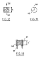
- FIG. 15 shows a device 130 according to an eighth exemplary embodiment of the invention.
- This device 130 is identical for its lower part to that shown in Figure 14, and includes a container which differs from the previous container 113 by the absence of hoop 122, replaced by an externally threaded skirt 131.
- the device 130 comprises an applicator 132 consisting of a gripping member and an applicator rod 123, the part of which lower is identical to that described with reference to FIG. 14.
- the rod 123 is connected to an internal part 133 fixed to the lower end of an internal tubular skirt 134 of the member gripping.
- An external flange 135 limits the insertion of the part internal 133 in the skirt 134.
- the gripping member comprises an external tubular skirt 136 coaxial with the internal skirt 134 and internally threaded to screw on the skirt 131 of the container.
- the collar 135 is pressed against the upper edge of the neck 118 to obtain a tight closure of the container.
- the thread of the skirt 131 is distant of the neck 118 because it thus avoids a deposit of product on the neck 118 hinders the closing of the container by soiling the threads of the skirts 131 and 136, the space provided between the opening of the container and the threads that can accommodate possible product overflows.
- FIG. 16 shows a block of foam 140 used as a wringing device, height h.
- this block of foam is split axially crosswise at 141 to form a passage allowing the crossing of the application element.
- the foam block may have at its upper part a conical recess 150, as illustrated in FIG. 19, for facilitate the retraction of the application element.
- the rod 151 (partially shown) supporting the application element is connected to the gripping 152 via a conical portion 153 intended to be housed in the recess 150 when the application element is in place inside the container, to limit the volume of air above the foam block.
- FIG. 20 shows a device 154 according to a ninth embodiment of the invention.
- This device 154 comprises a container formed by the assembly an upper part 155 and a lower part 156, the part upper 155 with an externally threaded neck 160 and on which screws the gripping member 161 of the applicator.
- a block of foam 157 comprising at least 5% of cells open is fixed by gluing or welding by its upper face 158 on a shoulder located at the base of the neck 160, inside a centering and sealing skirt 162, the internal diameter of which roughly corresponds to the outside diameter of the foam block 157 and whose height represents about a quarter of the height of the foam block 157.
- this element has been represented in this figure application in the form of a hollow body 163, having a cavity 164 capable of accommodating a reserve of product.
- the upper part 155 of the container is shaped so to provide a space around the foam block 157 and the skirt 162 annular 159 which allows the foam to deform axially and radially when the applicator element 163 passes.
- FIG. 21 Partly shown in FIG. 21 is a device 165 according to a tenth exemplary embodiment of the invention.
- the applicator is not shown, which can be of any type suitable for the use to be made of it.
- the device 165 has the particularity of comprising a wiping lip 166 in addition to a wiping member constituted by a foam block 167 split axially and having at least 5% of open cells.
- the device 165 comprises a cylindrical container 168 and the wiping lip 166 is produced in a tip 169 which comes insert into the upper part of the container 168.
- the wiping lip 166 partially covers the face upper 170 of foam block 167, leaving a diameter passage adapted to the nature and shape of the application element.
- the tip 169 comprises a tubular wall 171 which defines a cylindrical housing in which the foam block 167 is received.
- a retaining piece 172 having in axial section the shape general of a U, which is housed at its upper part in a annular space present between the wall 171 and the container 168 and snaps onto reliefs 173 of the wall 171.
- the piece of retainer 172 is pierced in its center for the passage of the element application.
- the tip 169 is shaped to guide the application element when it enters the container 168, and has a surface 173 converging towards the wiping lip 166.
- FIG. 22 shows a device 175 in accordance with an eleventh embodiment of the invention.
- This device includes, like the previous one, a lip spin 176 in addition to a block of foam 177 comprising at least 5% open cells.
- the wiping lip 176 is formed in a nozzle 178 which is inserted into the neck of the container.
- the wiping lip is extended above by a wall conical 179, serving as a guide during the retraction of the element application.
- the foam block 177 is hollowed out at its upper part to partially engage around the wiping lip 176.
- the presence of a wall guiding the application element towards the center of the block of foam allows when returning the applicator to avoid damage the application element, especially when the diameter outside of the foam block is relatively small.
- the application element may not be presented in the center of the foam block, where finds the axial recess or the slots allowing the passage of the foam block.
- the effort that would be required to insert the application element in the foam block could then be relatively large, especially if the foam block is weak diameter.
- the foam block which is fixed at its periphery has a rigid wall, would hardly deform into a hollow to guide the applicator element towards the center of the foam block.
- the foam block is glued or welded to the tip 169 or 178, made for example of polyethylene or polypropylene.
- the foam block can receive, prior to its attachment, an appropriate surface treatment.
- the container can be filled before the establishment of the wiper member, or after. In this last case, we can even take advantage of the porosity of the foam to achieve filling the container through it.
- the container can be offered for sale and the applicator separately, the container being in this case provided with a closure cap to be replaced by the applicator when use.
- the container sold separately then constitutes an element of refill intended to replace an empty container, with conservation of the same applicator.
- the invention makes it possible to wring so particularly satisfactory the application element and contributes to obtaining a neat makeup. If necessary, we can fix a small mirror on the outer wall of the container.
- the invention also allows, if necessary, the spinning of a application element whose maximum diameter is less than or equal to that of the applicator rod, which is not possible with the wiping members known from the prior art. Thanks to its great deformability, the foam can be applied to the rod and clean the latter so as to avoid the formation of a solid deposit likely to flake later, while spinning effective of the application element, even if the latter has a diameter greater or less than that of the rod.
- the invention also makes it possible to improve the emptying of the container insofar as the deformability of the wiper member allows to tilt the applicator rod to come with the element application, as shown in dotted lines in Figure 1, take of product on regions of the inner surface of the container inaccessible in the prior art.
- the rod the applicator is straight at rest, it is possible without leaving the frame of the invention use a curved rod, taking advantage of the fact that the dewatering member allows, thanks to its deformability, to house this in the container.
- the invention also advantageously makes it possible to use a applicator element having a cross-sectional shape not symmetrical of revolution, oval, square or other.
- the application member also constitutes a filter particularly effective in retaining possible product residues having dried and being deposited on the application element or on the applicator rod.
- the invention also makes it possible to avoid the emission of a noise of suction when passing through the wiper member, due to the porosity foam.
- the invention preferably applies to packaging and the application of a liquid or pasty product.
Claims (29)
- Vorrichtung zum Aufbewahren und Auftragen eines flüssigen, breiförmigen oder pulverförmigen Produkts, insbesondere eines kosmetischen Produkts, die einen an einem Ende offenen, das Produkt enthaltenden Behälter und einen Auftrager umfasst, der eine an einem Ende mit einem Auftragelement und am anderen Ende mit einem Greiforgan versehene Stange besitzt, wobei das Auftragelement im Kontakt mit einem elastisch verformbaren Abstreiforgan in den Behälter eingeführt und aus diesem herausgezogen wird, wobei das Auftragelement in dem Behälter untergebracht ist, wenn dieser geschlossen ist, und das Abstreiforgan mindestens zum Teil aus einem Schaumstoff besteht, der mit dem Boden des Behälters einen freien Raum bildet, in dem das Produkt frei enthalten ist (11;16;18;19;21;23;37;45;64;86;110;129;140), dadurch gekennzeichnet, dass der Schaumstoff mindestens 5 % offene Zellen besitzt und einen Schlitz aufweist, der sich bei Durchgang des Auftragelements öffnen kann.
- Vorrichtung nach Anspruch 1, dadurch gekennzeichnet, dass der Schaumstoff nur den oberen Teil des Behälters einnimmt.
- Vorrichtung nach dem vorhergehenden Anspruch, dadurch gekennzeichnet, dass der obere Teil des Behälters so ausgeformt ist, dass er um den Schaumstoff herum einen ringförmigen Raum bildet, der es dem Schaumstoff gestattet, sich bei dem Durchgang des Auftragelements axial und radial zu verformen.
- Vorrichtung nach einem der vorhergehenden Ansprüche, dadurch gekennzeichnet, dass der Schaumstoff mit seiner Oberseite an einer Schulter des Behälters befestigt ist.
- Vorrichtung nach einem der vorhergehenden Ansprüche, dadurch gekennzeichnet, dass die Stange einen Abschnitt besitzt, der sich im Kontakt mit dem Schaumstoffblock befindet, ohne ihn zu sehr zu komprimieren, wobei dieser Abschnitt an seinem unteren Ende an einen verbreiterten Teil anschließt, der zur Befestigung des Auftragelements dient.
- Vorrichtung nach einem der vorhergehenden Ansprüche, dadurch gekennzeichnet, dass die Unterseite des Schaumstoffs frei ist.
- Vorrichtung nach einem der vorhergehenden Ansprüche, dadurch gekennzeichnet, dass das Greiforgan ausgebildet ist, um praktisch das ganze Luftvolumen über dem Schaumstoff einzunehmen, wenn es auf dem Behälter an Platz ist.
- Vorrichtung nach einem der vorhergehenden Ansprüche, dadurch gekennzeichnet, dass das Auftragelement im Querschnitt eine nicht rotationssymmetrische Form besitzt.
- Vorrichtung nach einem der vorhergehenden Ansprüche, dadurch gekennzeichnet, dass der Schaumstoff mit der Stange des Auftragers in Kontakt ist, wenn dieser auf dem Behälter an Platz ist.
- Vorrichtung nach einem der vorhergehenden Ansprüche, dadurch gekennzeichnet, dass der Schaumstoff so angeordnet ist, dass er mit dem an das Greiforgan anschließenden Stangenabschnitt in Kontakt ist, wenn der Auftrager (114) auf dem Behälter an Platz ist.
- Vorrichtung nach Anspruch 1, dadurch gekennzeichnet, dass der Schaumstoff mit dem Produkt in ständigem Kontakt ist.
- Vorrichtung nach einem der vorhergehenden Ansprüche, dadurch gekennzeichnet, dass das Abstreiforgan einen Schaumstoffblock (16;110) umfasst, der an seinem Umfang auf mindestens einem Teil seiner Höhe versteift ist.
- Vorrichtung nach einem der vorhergehenden Ansprüche, dadurch gekennzeichnet, dass die Stange (103;123) des Auftragers einen mittleren Abschnitt und einen an das Auftragelement anschließenden Abschnitt (109;127) aufweist, wobei der Außendurchmesser dieses an das Auftragelement anschließenden Abschnitts größer als der des mittleren Abschnitts ist.
- Vorrichtung nach einem der vorhergehenden Ansprüche, dadurch gekennzeichnet, dass das Produkt flüssig ist.
- Vorrichtung nach einem der vorhergehenden Ansprüche, dadurch gekennzeichnet, dass die Stange des Auftragers geradlinig ist und dass der Behälter eine langgestreckte Form mit einer Mündung besitzt, deren Öffnungsbreite breit genug ist, um eine Neigung der Stange im Inneren des Behälters von mindestens 10° gegen die Längsachse des Behälters zu gestatten.
- Vorrichtung nach einem der vorhergehen Ansprüche mit Ausnahme von Anspruch 6, dadurch gekennzeichnet, dass das Abstreiforgan eine starre Scheibe (28) aufweist, die durch den Auftrager bei dessen Ausziehen mitgenommen werden kann, um den Schaumstoff auszudrücken.
- Vorrichtung nach einem der vorhergehenden Ansprüche, dadurch gekennzeichnet, dass das Abstreiforgan mehrere Schaumstoffblöcke (25;26;27) mit verschiedenen Dichten umfasst.
- Vorrichtung nach einem der vorhergehenden Ansprüche mit Ausnahme des Anspruchs 6, dadurch gekennzeichnet, dass das Abstreiforgan (11) axial im Inneren des Behälters durch eine Einschnürung blockiert wird, die von einer nach innen gebogenen flexiblen ringförmigen Wand (44) gebildet wird, die durch Formguss mit dem Behälter (40) gebildet ist.
- Vorrichtung nach einem der vorhergehenden Ansprüche mit Ausnahme des Anspruchs 5, dadurch gekennzeichnet, dass der Behälter (54) durch Zusammenfügen von zwei Teilen (56;57) gebildet ist, wobei das Abstreiforgan in einem der Teile durch den anderen Teil axial blockiert wird.
- Vorrichtung nach einem der vorhergehenden Ansprüche, dadurch gekennzeichnet, dass das Abstreiforgan in seiner Mitte axial ausgespart ist.
- Vorrichtung nach einem der vorhergehenden Ansprüche, dadurch gekennzeichnet, dass sie außerdem eine Abstreiflippe (166;176) aufweist.
- Vorrichtung nach einem der vorhergehenden Ansprüche, dadurch gekennzeichnet, dass die Abstreiflippe an der äußeren Mündung des Behälters gelegen ist und dass sie nach außen durch eine Wand (173;179) verlängert ist, die divergiert, indem sie sich vom Schaumstoff entfernt.
- Vorrichtung nach einem der vorhergehenden Ansprüche, dadurch gekennzeichnet, dass der Schaumstoff eine konische Aussparung (150) besitzt.
- Vorrichtung nach einem der vorhergehenden Ansprüche, dadurch gekennzeichnet, dass das Greiforgan den Behälter dicht verschließen kann, wenn es auf diesem an Platz ist.
- Vorrichtung nach einem der vorhergehenden Ansprüche, dadurch gekennzeichnet, dass das Greiforgan auf ein Gewinde (131) des Behälters aufgeschraubt werden kann, dessen Durchmesser beträchtlich größer als der der Öffnung des Behälters ist.
- Vorrichtung nach einem der vorhergehenden Ansprüche, dadurch gekennzeichnet, dass der Behälter eine doppelte Wand (58,60;77,80;92,94;115,120) besitzt.
- Vorrichtung nach einem der vorhergehenden Ansprüche, dadurch gekennzeichnet, dass das Auftragelement aus der folgenden Liste ausgewählt ist: Pinsel, Schaumstoff, Filz, beflockter Kunststoff oder Elastomeraufsatz.
- Vorrichtung nach einem der vorhergehenden Ansprüche mit Ausnahme von Anspruch 6, dadurch gekennzeichnet, dass der Schaumstoff in einer Aufnahme des Behälters angeordnet ist, deren Höhe (h') kleiner als die axiale Abmessung (h) des Schaumstoffs vor seiner Montage in dem Behälter ist.
- Mit einem Abstreiforgan versehener Behälter gemäß einem der vorhergehenden Ansprüche, der mit einer Verschlusskapsel versehen ist, um eine Nachfüllelement zu bilden.
Priority Applications (4)
| Application Number | Priority Date | Filing Date | Title |
|---|---|---|---|
| EP01131019A EP1199005B1 (de) | 1996-02-28 | 1997-02-27 | Vorrichtung zum Aufbewahrung und Auftragen, und Nachfüllelement für eine solche Vorrichtung |
| EP01131021A EP1190641B1 (de) | 1996-02-28 | 1997-02-27 | Vorrichtung zum Aufbewahren und Auftragen |
| EP01131020A EP1419710B1 (de) | 1996-02-28 | 1997-02-27 | Vorrichtung zum Aufbewahren und Auftragen, und Nachfüllelement für eine solche Vorrichtung |
| EP01131016A EP1199004B1 (de) | 1996-02-28 | 1997-02-27 | Vorrichtung zum Aufbewahren und Auftragen, und Nachfüllelement für eine solche Vorrichtung |
Applications Claiming Priority (3)
| Application Number | Priority Date | Filing Date | Title |
|---|---|---|---|
| FR9602477 | 1996-02-28 | ||
| FR9602477A FR2745272B1 (fr) | 1996-02-28 | 1996-02-28 | Dispositif de conditionnement et d'application et element de recharge pour un tel dispositif |
| PCT/FR1997/000353 WO1997031553A1 (fr) | 1996-02-28 | 1997-02-27 | Dispositif de conditionnement et d'application et element de recharge pour un tel dispositif |
Related Child Applications (4)
| Application Number | Title | Priority Date | Filing Date |
|---|---|---|---|
| EP01131019A Division EP1199005B1 (de) | 1996-02-28 | 1997-02-27 | Vorrichtung zum Aufbewahrung und Auftragen, und Nachfüllelement für eine solche Vorrichtung |
| EP01131016A Division EP1199004B1 (de) | 1996-02-28 | 1997-02-27 | Vorrichtung zum Aufbewahren und Auftragen, und Nachfüllelement für eine solche Vorrichtung |
| EP01131020A Division EP1419710B1 (de) | 1996-02-28 | 1997-02-27 | Vorrichtung zum Aufbewahren und Auftragen, und Nachfüllelement für eine solche Vorrichtung |
| EP01131021A Division EP1190641B1 (de) | 1996-02-28 | 1997-02-27 | Vorrichtung zum Aufbewahren und Auftragen |
Publications (2)
| Publication Number | Publication Date |
|---|---|
| EP0824329A1 EP0824329A1 (de) | 1998-02-25 |
| EP0824329B1 true EP0824329B1 (de) | 2002-07-31 |
Family
ID=9489662
Family Applications (5)
| Application Number | Title | Priority Date | Filing Date |
|---|---|---|---|
| EP01131019A Expired - Lifetime EP1199005B1 (de) | 1996-02-28 | 1997-02-27 | Vorrichtung zum Aufbewahrung und Auftragen, und Nachfüllelement für eine solche Vorrichtung |
| EP01131021A Expired - Lifetime EP1190641B1 (de) | 1996-02-28 | 1997-02-27 | Vorrichtung zum Aufbewahren und Auftragen |
| EP01131016A Expired - Lifetime EP1199004B1 (de) | 1996-02-28 | 1997-02-27 | Vorrichtung zum Aufbewahren und Auftragen, und Nachfüllelement für eine solche Vorrichtung |
| EP01131020A Expired - Lifetime EP1419710B1 (de) | 1996-02-28 | 1997-02-27 | Vorrichtung zum Aufbewahren und Auftragen, und Nachfüllelement für eine solche Vorrichtung |
| EP97907143A Expired - Lifetime EP0824329B1 (de) | 1996-02-28 | 1997-02-27 | Vorrichtung zum aufbewahren und auftragen, und nachfüllelement für eine solche vorrichtung |
Family Applications Before (4)
| Application Number | Title | Priority Date | Filing Date |
|---|---|---|---|
| EP01131019A Expired - Lifetime EP1199005B1 (de) | 1996-02-28 | 1997-02-27 | Vorrichtung zum Aufbewahrung und Auftragen, und Nachfüllelement für eine solche Vorrichtung |
| EP01131021A Expired - Lifetime EP1190641B1 (de) | 1996-02-28 | 1997-02-27 | Vorrichtung zum Aufbewahren und Auftragen |
| EP01131016A Expired - Lifetime EP1199004B1 (de) | 1996-02-28 | 1997-02-27 | Vorrichtung zum Aufbewahren und Auftragen, und Nachfüllelement für eine solche Vorrichtung |
| EP01131020A Expired - Lifetime EP1419710B1 (de) | 1996-02-28 | 1997-02-27 | Vorrichtung zum Aufbewahren und Auftragen, und Nachfüllelement für eine solche Vorrichtung |
Country Status (10)
| Country | Link |
|---|---|
| US (5) | US6305861B1 (de) |
| EP (5) | EP1199005B1 (de) |
| JP (1) | JP3681399B2 (de) |
| CN (1) | CN1101165C (de) |
| BR (1) | BR9702097A (de) |
| DE (5) | DE69734300T2 (de) |
| ES (5) | ES2269292T3 (de) |
| FR (1) | FR2745272B1 (de) |
| MX (1) | MX9708207A (de) |
| WO (1) | WO1997031553A1 (de) |
Cited By (7)
| Publication number | Priority date | Publication date | Assignee | Title |
|---|---|---|---|---|
| EP1481607A1 (de) | 2003-05-27 | 2004-12-01 | L'oreal | Vorrichtung zum Aufbewahren und Auftragen eines Produktes mit einem Abstreifelement |
| EP1726235A2 (de) | 2005-05-24 | 2006-11-29 | L'oreal | Vorrichtung zum Aufbewahren und zum Auftragen |
| US7866906B2 (en) | 2004-07-13 | 2011-01-11 | L'oreal | Packaging and applicator device for applying a cosmetic or another care product |
| US7918619B2 (en) | 2005-05-24 | 2011-04-05 | L'oreal | Packaging and applicator device, and method of making up skin or lips |
| US7967519B2 (en) | 2003-05-27 | 2011-06-28 | L'oreal | Device for packaging and applying a substance, the device including a wiper member |
| USD892614S1 (en) | 2018-06-11 | 2020-08-11 | Ecolab Usa Inc. | Cap for container |
| WO2021259680A1 (en) | 2020-06-26 | 2021-12-30 | L'oreal | Cosmetic applicator having a cavity supported by support arms |
Families Citing this family (78)
| Publication number | Priority date | Publication date | Assignee | Title |
|---|---|---|---|---|
| FR2745481B1 (fr) | 1996-02-29 | 1998-04-30 | Oreal | Brosse progressive pour appliquer un produit cosmetique, notamment du mascara |
| USRE38397E1 (en) | 1996-11-13 | 2004-01-27 | L'oreal | Brush for applying a cosmetic product and make-up device comprising it |
| FR2762494B1 (fr) * | 1997-04-28 | 1999-06-25 | Oreal | Applicateur et ensemble de conditionnement et d'application utilisant un tel applicateur |
| FR2762509B1 (fr) | 1997-04-28 | 2003-03-07 | Oreal | Composition cosmetique ou dermatologique comprenant un polymere filmogene, procede de maquillage et de traitement non therapeutique |
| FR2771077B1 (fr) | 1997-11-14 | 2000-01-14 | Oreal | Dispositif de conditionnement et d'application comportant un recipient, un applicateur ergonomique et un organe d'essorage |
| FR2774296B1 (fr) * | 1998-01-30 | 2000-06-09 | Oreal | Dispositif pour l'application d'une composition filmogene |
| FR2777432B1 (fr) * | 1998-04-17 | 2000-07-13 | Lvmh Rech | Boitier de maquillage des cils de l'oeil |
| US6276856B1 (en) * | 1999-01-12 | 2001-08-21 | The Procter & Gamble Company | Self cleaning dip-in package for liquids |
| US20050191337A1 (en) * | 1999-03-31 | 2005-09-01 | L'oreal S.A. | Patch with a magnetic field effect |
| CN1182809C (zh) | 1999-07-21 | 2005-01-05 | 莱雅公司 | 往角质纤维上涂抹制品的梳子、涂抹装置及其用途 |
| US20040234321A1 (en) * | 2001-04-25 | 2004-11-25 | Breidenbach Diane C. | Dual cosmetic container |
| FR2805720B1 (fr) * | 2000-03-03 | 2002-08-16 | Oreal | Dispositif comprenant un applicateur et/ou un organe d'essorage magnetique |
| FR2808980B1 (fr) * | 2000-05-19 | 2002-12-20 | Oreal | Ensemble pour le conditionnement et l'application d'une poudre liquide |
| FR2812176B1 (fr) * | 2000-07-26 | 2003-01-10 | Oreal | Applicateur pour l'application d'un produit sur des fibres keratiniques, ensemble d'application equipe d'un tel applicateur, et utilisation de cet ensemble |
| FR2821536B1 (fr) | 2001-03-01 | 2003-05-16 | Oreal | Brosse pour l'application d'un produit sur les fibres keratiniques |
| FR2821533B1 (fr) | 2001-03-01 | 2004-01-23 | Oreal | Brosse pour l'application d'un produit sur les fibres keratiniques |
| FR2821532B1 (fr) | 2001-03-01 | 2003-12-12 | Oreal | Brosse pour l'application d'un produit sur les fibres keratiniques |
| FR2830240B1 (fr) | 2001-10-01 | 2004-08-20 | Oreal | Dispositif de conditionnement d'un produit, notamment un produit cosmetique et/ou de soins |
| US7303347B1 (en) * | 2002-11-19 | 2007-12-04 | Duncan Georgetta P | Stain removal kit |
| US20040096259A1 (en) * | 2002-11-20 | 2004-05-20 | Theile Frederick C. | Device including recessed container and method of cosmetic product application |
| US20050033194A1 (en) * | 2003-08-09 | 2005-02-10 | Fischer Nathan R. | Method and apparatus for sampling and collection of cervical cells |
| FR2881931B1 (fr) * | 2005-02-11 | 2007-04-27 | Oreal | Dispositif de conditionnement et d'application |
| FR2882506B1 (fr) | 2005-02-25 | 2007-05-18 | Oreal | Procede de maquillage au moyen d'un applicateur vibrant |
| DE202006007492U1 (de) * | 2005-06-24 | 2006-08-24 | Jenner, Günter | Verbindungsteil für Applikatoren |
| US20070181143A1 (en) * | 2005-12-30 | 2007-08-09 | Antonio Montoli | Flocked cosmetic applicators |
| FR2908018B1 (fr) | 2006-11-02 | 2009-10-30 | Oreal | Applicateur pour appliquer un produit sur les cils ou les sourcils |
| FR2918255B1 (fr) * | 2007-07-05 | 2009-10-02 | Chanel Parfums Beaute Sas Unip | Dispositif de maquillage comprenant un essoreur |
| FR2934477B1 (fr) | 2008-07-31 | 2012-12-21 | Oreal | Brosse a mascara comportant des poils de differents diametres. |
| EP2165623B1 (de) * | 2008-09-23 | 2011-12-14 | Albéa Services | Kosmetikapplikator mit Doppelabstreifer |
| US8434959B2 (en) * | 2009-01-22 | 2013-05-07 | Kyle M. Bennett | Cosmetic container with mirrored element |
| DE102009011026B4 (de) * | 2009-03-02 | 2010-11-18 | Geka Brush Gmbh | Kosmetikeinheit mit Schwenkverschluss |
| CN102427746A (zh) * | 2009-05-18 | 2012-04-25 | Elc管理有限责任公司 | 可压缩化妆用涂抹器 |
| FR2945921B1 (fr) * | 2009-05-28 | 2014-07-25 | Rexam Beauty & Closures Inc | Recipient cosmetique |
| US8944712B2 (en) * | 2010-03-12 | 2015-02-03 | Hct Asia Ltd | Cosmetic bottle with automatic extending applicator |
| BRPI1001200A2 (pt) * | 2010-04-19 | 2011-12-06 | Sandra Regina Bulcao Palmeira | aparelho tubular para higienização dos orifìcios do corpo |
| JP4840831B2 (ja) | 2010-04-27 | 2011-12-21 | 株式会社 資生堂 | 化粧用塗布体 |
| KR200464879Y1 (ko) * | 2010-10-13 | 2013-01-22 | (주)아모레퍼시픽 | 펌프식 화장품용기 |
| US8721210B2 (en) | 2010-11-18 | 2014-05-13 | Hct Asia Ltd | Cosmetic multi-layered wiper |
| FR2969127B1 (fr) * | 2010-12-21 | 2014-04-18 | Oreal | Dispositif de conditionnement d'un produit, notamment cosmetique, avec un organe d'etancheite |
| DE102010055561B4 (de) * | 2010-12-23 | 2015-12-31 | Heraeus Medical Gmbh | Beschichtungsverfahren und Beschichtungsvorrichtung |
| FR2979807B1 (fr) | 2011-09-09 | 2015-03-27 | Oreal | Applicateur pour appliquer un produit sur les cils ou les sourcils |
| US8915355B2 (en) | 2011-09-23 | 2014-12-23 | Robert MONSON | Flux applicator brush and flux container system |
| US20130101334A1 (en) | 2011-10-24 | 2013-04-25 | Avon Products, Inc. | Functional Dynamic Cosmetic Package |
| WO2014003480A1 (ko) * | 2012-06-29 | 2014-01-03 | (주)아모레퍼시픽 | 도포용 스펀지를 포함하는 화장료 조성물 용기 |
| FR2992839B1 (fr) * | 2012-07-09 | 2014-07-25 | Albea Services | Reservoir de distributeur applicateur pour un produit cosmetique fluide ou pateux et distributeur applicateur associe |
| WO2015027338A1 (en) * | 2013-08-30 | 2015-03-05 | Kapitor-Robertson Rose | Paint touch up kit |
| FR3024714B1 (fr) * | 2014-08-06 | 2016-09-09 | Vuitton Louis Sa | Systeme pour tester un parfum |
| WO2016036761A1 (en) | 2014-09-02 | 2016-03-10 | HCT Group Holdings Limited | Container with dispensing tip |
| US9867448B2 (en) | 2014-09-15 | 2018-01-16 | HCT Group Holdings Limited | Container with collapsible applicator |
| US20160081453A1 (en) * | 2014-09-24 | 2016-03-24 | World Wide Packaging, Inc. | Fluid Container |
| FR3035307B1 (fr) * | 2015-04-23 | 2018-10-26 | Albea Services | Receptacle, notamment flaconnette destinee a recevoir un produit cosmetique |
| FR3036592B1 (fr) * | 2015-05-26 | 2017-05-19 | Oreal | Ensemble de conditionnement et d'application d'un produit cosmetique comprenant au moins un solvant volatil |
| KR101714348B1 (ko) * | 2015-06-22 | 2017-03-09 | (주)연우 | 스폰지 와이퍼가 구비된 용기 |
| EP3319476A4 (de) | 2015-07-10 | 2019-05-29 | HCT Group Holding Limited | Dekorative wischer für kosmetikbehälter |
| US9993059B2 (en) | 2015-07-10 | 2018-06-12 | HCT Group Holdings Limited | Roller applicator |
| KR101573703B1 (ko) * | 2015-08-07 | 2015-12-02 | 변영찬 | 와이퍼가 구비된 스크레이퍼용 화장품 용기 |
| FR3042392B1 (fr) * | 2015-10-20 | 2021-03-19 | Oreal | Ensemble de conditionnement de produit cosmetique a double paroi |
| WO2017075816A1 (zh) * | 2015-11-06 | 2017-05-11 | 陈文胜 | 化妆品容器 |
| US10244847B2 (en) | 2016-03-16 | 2019-04-02 | HCT Group Holdings Limited | Cosmetic applicator with aligning cap |
| USD818641S1 (en) | 2016-03-16 | 2018-05-22 | HCT Group Holdings Limited | Cosmetics applicator with cap |
| US10611048B1 (en) | 2016-05-27 | 2020-04-07 | SmartFume Co. | Wood treatment device |
| FR3053220A1 (fr) * | 2016-06-29 | 2018-01-05 | Albea Services | Ensemble applicateur pour produit cosmetique |
| FR3055196B1 (fr) * | 2016-08-25 | 2022-07-01 | Oreal | Applicateur de produit cosmetique articule et ensemble de conditionnement et d'application associe |
| KR102349215B1 (ko) * | 2016-09-30 | 2022-01-10 | (주)아모레퍼시픽 | 다양한 배출특성을 가지는 담지체 및 이를 포함하는 화장용구 |
| US10660419B2 (en) | 2016-12-15 | 2020-05-26 | Elc Management Llc | Packaged skin treatment composition and method |
| USD866080S1 (en) | 2017-03-14 | 2019-11-05 | HCT Group Holdings Limited | Cosmetic stick |
| USD842548S1 (en) | 2017-03-14 | 2019-03-05 | HCT Group Holdings Limited | Cosmetic applicator |
| USD841235S1 (en) | 2017-03-15 | 2019-02-19 | HCT Group Holdings Limited | Spatula cosmetic applicator |
| FR3066079B1 (fr) * | 2017-05-10 | 2021-06-11 | Oreal | Essoreur pour recipient de produit cosmetique |
| USD850007S1 (en) | 2017-07-07 | 2019-05-28 | HCT Group Holdings Limited | Cosmetic stick |
| USD846197S1 (en) | 2017-07-07 | 2019-04-16 | HCT Group Holdings Limited | Combined cosmetic stick and compact |
| US10517372B2 (en) * | 2017-08-31 | 2019-12-31 | L'oreal | Wiper assembly |
| FR3074021B1 (fr) * | 2017-11-28 | 2021-02-19 | Oreal | Dispositif de conditionnement et d’application d’une composition cosmetique biphasique |
| US10874193B2 (en) | 2018-03-14 | 2020-12-29 | HCT Group Holdings Limited | Wheel actuated cosmetic stick |
| USD886633S1 (en) | 2018-05-18 | 2020-06-09 | HCT Group Holdings Limited | Cosmetic dispenser with cap |
| USD889745S1 (en) | 2018-09-06 | 2020-07-07 | HCT Group Holdings Limited | Dual purpose makeup applicator |
| USD910236S1 (en) | 2018-11-20 | 2021-02-09 | HCT Group Holdings Limited | Ball tip applicator |
| FR3091983B1 (fr) | 2019-01-28 | 2021-04-30 | Texen Services | Application d’un produit sur une partie superficielle du corps humain |
Family Cites Families (24)
| Publication number | Priority date | Publication date | Assignee | Title |
|---|---|---|---|---|
| GB190628813A (en) * | 1906-12-18 | 1907-10-24 | William Lister Newcombe | Improvements in or relating to Caps or Covers to Bottles for the purpose of containing Adhesive Paste, Mucilage, Gum and the like. |
| US2001086A (en) * | 1931-03-21 | 1935-05-14 | Mundet & Son Inc L | Closure |
| GB452640A (en) | 1936-02-25 | 1936-08-26 | Ralph Barnes | Improvements in or relating to jars, bottles and the like containers |
| CH338327A (fr) * | 1957-09-12 | 1959-05-15 | Bouchard Marcel | Dispositif pour essuyer la jauge d'huile d'une machine |
| US3072953A (en) * | 1958-05-07 | 1963-01-15 | United Shoe Machinery Corp | Applicator tubes |
| US3033213A (en) * | 1958-05-26 | 1962-05-08 | Rubinstein Inc H | Mascara applicator |
| US3010140A (en) * | 1959-04-02 | 1961-11-28 | Walter N Thomas | Liquid shoe polish applicator |
| US3150220A (en) * | 1961-05-18 | 1964-09-22 | Metal Box Co Ltd | Method of making applicator-type containers |
| US3132653A (en) * | 1961-12-22 | 1964-05-12 | Gazdik Eva | Multi-applicator for liquid cosmetic |
| US3146806A (en) * | 1962-08-09 | 1964-09-01 | Ginsburg Henry | Dispensing container for liquids |
| FR2098940A5 (de) * | 1970-07-31 | 1972-03-10 | Aubry Albert | |
| FR2285101A1 (fr) * | 1974-09-23 | 1976-04-16 | Bellon Labor Sa Roger | Dispositif applicateur d'ombre a paupieres en poudre |
| US4282891A (en) * | 1978-06-05 | 1981-08-11 | Revelations Antoine Ltee | Fingernail treating device |
| US4440181A (en) * | 1981-01-05 | 1984-04-03 | Scherer John S | Nail polish remover kit |
| WO1982002326A1 (en) * | 1981-01-05 | 1982-07-22 | John Stephen Scherer | Nail polish remover kit |
| US4380841A (en) * | 1981-02-25 | 1983-04-26 | Hopkins Manufacturing Corporation | Oil dip stick wiper unit |
| US4446965A (en) * | 1981-09-14 | 1984-05-08 | Alexandra Montiel | Applicator for liquids |
| FR2567006A1 (fr) | 1984-07-06 | 1986-01-10 | Araujo Aides | Dispositif permettant de traiter les extremites des doigts des mains. |
| DE8609637U1 (de) | 1986-04-09 | 1986-06-05 | Mackenbach, Klaus, 4792 Bad Lippspringe | Reinigungsbehältnis |
| FR2624403B1 (de) * | 1987-12-11 | 1990-05-18 | Emballages Conseils Etudes | |
| US4931484A (en) | 1988-10-13 | 1990-06-05 | Applied Extrusion Technologies, Inc. | Extruded ethylenic polymer foam containing both open and closed cells |
| GB2243762A (en) * | 1990-05-01 | 1991-11-13 | Michael Joseph Mahon | Dipstick cleaner |
| US5188131A (en) * | 1991-12-16 | 1993-02-23 | Charlotte Toll | Eyelash mascara case and applicator |
| DE19516764A1 (de) * | 1995-05-06 | 1996-11-07 | Henkel Raycap Produktie Bv | Behälter für ein fließfähiges Produkt |
-
1996
- 1996-02-28 FR FR9602477A patent/FR2745272B1/fr not_active Expired - Fee Related
-
1997
- 1997-02-25 US US08/805,934 patent/US6305861B1/en not_active Expired - Lifetime
- 1997-02-27 DE DE69734300T patent/DE69734300T2/de not_active Expired - Lifetime
- 1997-02-27 DE DE69734365T patent/DE69734365T2/de not_active Expired - Lifetime
- 1997-02-27 DE DE69736993T patent/DE69736993T2/de not_active Expired - Lifetime
- 1997-02-27 JP JP53067397A patent/JP3681399B2/ja not_active Expired - Fee Related
- 1997-02-27 ES ES01131020T patent/ES2269292T3/es not_active Expired - Lifetime
- 1997-02-27 ES ES01131016T patent/ES2246990T3/es not_active Expired - Lifetime
- 1997-02-27 DE DE69736571T patent/DE69736571T2/de not_active Expired - Lifetime
- 1997-02-27 EP EP01131019A patent/EP1199005B1/de not_active Expired - Lifetime
- 1997-02-27 EP EP01131021A patent/EP1190641B1/de not_active Expired - Lifetime
- 1997-02-27 MX MX9708207A patent/MX9708207A/es unknown
- 1997-02-27 CN CN97190265A patent/CN1101165C/zh not_active Expired - Fee Related
- 1997-02-27 ES ES01131021T patent/ES2246991T3/es not_active Expired - Lifetime
- 1997-02-27 WO PCT/FR1997/000353 patent/WO1997031553A1/fr active IP Right Grant
- 1997-02-27 BR BR9702097A patent/BR9702097A/pt not_active IP Right Cessation
- 1997-02-27 EP EP01131016A patent/EP1199004B1/de not_active Expired - Lifetime
- 1997-02-27 DE DE69714357T patent/DE69714357T2/de not_active Expired - Lifetime
- 1997-02-27 ES ES97907143T patent/ES2180026T3/es not_active Expired - Lifetime
- 1997-02-27 ES ES01131019T patent/ES2275610T3/es not_active Expired - Lifetime
- 1997-02-27 EP EP01131020A patent/EP1419710B1/de not_active Expired - Lifetime
- 1997-02-27 EP EP97907143A patent/EP0824329B1/de not_active Expired - Lifetime
-
1999
- 1999-03-04 US US09/262,361 patent/US6290416B1/en not_active Expired - Lifetime
- 1999-03-04 US US09/262,013 patent/US6261017B1/en not_active Expired - Lifetime
- 1999-03-04 US US09/262,360 patent/US6283659B1/en not_active Expired - Lifetime
- 1999-03-04 US US09/262,014 patent/US6076985A/en not_active Expired - Lifetime
Cited By (9)
| Publication number | Priority date | Publication date | Assignee | Title |
|---|---|---|---|---|
| EP1481607A1 (de) | 2003-05-27 | 2004-12-01 | L'oreal | Vorrichtung zum Aufbewahren und Auftragen eines Produktes mit einem Abstreifelement |
| US7967519B2 (en) | 2003-05-27 | 2011-06-28 | L'oreal | Device for packaging and applying a substance, the device including a wiper member |
| US7866906B2 (en) | 2004-07-13 | 2011-01-11 | L'oreal | Packaging and applicator device for applying a cosmetic or another care product |
| EP1726235A2 (de) | 2005-05-24 | 2006-11-29 | L'oreal | Vorrichtung zum Aufbewahren und zum Auftragen |
| US7918619B2 (en) | 2005-05-24 | 2011-04-05 | L'oreal | Packaging and applicator device, and method of making up skin or lips |
| USD892614S1 (en) | 2018-06-11 | 2020-08-11 | Ecolab Usa Inc. | Cap for container |
| USD903504S1 (en) | 2018-06-11 | 2020-12-01 | Ecolab Usa Inc. | Pouch container |
| WO2021259680A1 (en) | 2020-06-26 | 2021-12-30 | L'oreal | Cosmetic applicator having a cavity supported by support arms |
| FR3111773A1 (fr) | 2020-06-26 | 2021-12-31 | L'oreal | Applicateur cosmétique à cavité supportée par des branches support |
Also Published As
Similar Documents
| Publication | Publication Date | Title |
|---|---|---|
| EP0824329B1 (de) | Vorrichtung zum aufbewahren und auftragen, und nachfüllelement für eine solche vorrichtung | |
| EP0916282B1 (de) | Vorrichtung zum Aufbewahren und Auftragen mit einem Behälter, einem ergonomischen Applikator und einem Abstreifer | |
| EP0549780B1 (de) | Vorrichtung zum auftragen von flüssigkeiten, insbesondere von kosmetischen produkten | |
| EP0761122B1 (de) | Transportierbare Einheit zum Verpacken eines Produktes, wie Mascara | |
| EP0923894B1 (de) | Verpackungseinheit für Mascara | |
| EP1312280B1 (de) | Verpackungseinheit zum Aufbewahren und Auftragen eines Produkts | |
| EP0701785B1 (de) | Vorrichtung zum Aufbewahren und Auftragen von Schminkprodukten | |
| EP1275322B1 (de) | Abstreifer mit vereinfachter Montage | |
| EP0688516B1 (de) | Mit einem perforierten Kolben versehene Auftragsvorrichtung für ein Produkt, insbesondere ein Schmink- oder Pflegeprodukt | |
| CA2170193C (fr) | Dispositif pour distribuer un produit liquide ou pulverulent comportant un organe d'essorage | |
| EP1304057A2 (de) | Auftragsvorrichtung für ein Kosmetikprodukt mit abnehmbarem Auftragsorgan | |
| FR2875110A1 (fr) | Dispositif d'application d'un produit muni d'un organe d'application amovible | |
| CH642523A5 (fr) | Ensemble reservoir - applicateur de maquillage. | |
| EP1369055A2 (de) | Applikator mit einer gelenkigen, mit einem Fingergriff verbundenen Stange | |
| FR2962890A1 (fr) | Applicateur a membrane | |
| FR2890296A1 (fr) | Dispositif de conditionnement et d'application d'un eye-liner liquide. | |
| CA2203291C (fr) | Ensemble de conditionnement pour mascara | |
| CA2203293C (fr) | Ensemble de conditionnement transportable pour un produit tel que du mascara |
Legal Events
| Date | Code | Title | Description |
|---|---|---|---|
| PUAI | Public reference made under article 153(3) epc to a published international application that has entered the european phase |
Free format text: ORIGINAL CODE: 0009012 |
|
| AK | Designated contracting states |
Kind code of ref document: A1 Designated state(s): DE ES FR GB IT |
|
| 17P | Request for examination filed |
Effective date: 19980225 |
|
| 17Q | First examination report despatched |
Effective date: 19991104 |
|
| GRAG | Despatch of communication of intention to grant |
Free format text: ORIGINAL CODE: EPIDOS AGRA |
|
| GRAG | Despatch of communication of intention to grant |
Free format text: ORIGINAL CODE: EPIDOS AGRA |
|
| GRAH | Despatch of communication of intention to grant a patent |
Free format text: ORIGINAL CODE: EPIDOS IGRA |
|
| GRAG | Despatch of communication of intention to grant |
Free format text: ORIGINAL CODE: EPIDOS AGRA |
|
| GRAH | Despatch of communication of intention to grant a patent |
Free format text: ORIGINAL CODE: EPIDOS IGRA |
|
| GRAA | (expected) grant |
Free format text: ORIGINAL CODE: 0009210 |
|
| AK | Designated contracting states |
Kind code of ref document: B1 Designated state(s): DE ES FR GB IT |
|
| REG | Reference to a national code |
Ref country code: GB Ref legal event code: FG4D Free format text: NOT ENGLISH |
|
| REF | Corresponds to: |
Ref document number: 69714357 Country of ref document: DE Date of ref document: 20020905 |
|
| GBT | Gb: translation of ep patent filed (gb section 77(6)(a)/1977) |
Effective date: 20021106 |
|
| REG | Reference to a national code |
Ref country code: ES Ref legal event code: FG2A Ref document number: 2180026 Country of ref document: ES Kind code of ref document: T3 |
|
| PLBE | No opposition filed within time limit |
Free format text: ORIGINAL CODE: 0009261 |
|
| STAA | Information on the status of an ep patent application or granted ep patent |
Free format text: STATUS: NO OPPOSITION FILED WITHIN TIME LIMIT |
|
| 26N | No opposition filed |
Effective date: 20030506 |
|
| PGFP | Annual fee paid to national office [announced via postgrant information from national office to epo] |
Ref country code: IT Payment date: 20120220 Year of fee payment: 16 |
|
| PGFP | Annual fee paid to national office [announced via postgrant information from national office to epo] |
Ref country code: GB Payment date: 20130228 Year of fee payment: 17 Ref country code: FR Payment date: 20130301 Year of fee payment: 17 Ref country code: DE Payment date: 20130220 Year of fee payment: 17 |
|
| PGFP | Annual fee paid to national office [announced via postgrant information from national office to epo] |
Ref country code: ES Payment date: 20140113 Year of fee payment: 18 |
|
| REG | Reference to a national code |
Ref country code: DE Ref legal event code: R119 Ref document number: 69714357 Country of ref document: DE |
|
| GBPC | Gb: european patent ceased through non-payment of renewal fee |
Effective date: 20140227 |
|
| REG | Reference to a national code |
Ref country code: FR Ref legal event code: ST Effective date: 20141031 |
|
| REG | Reference to a national code |
Ref country code: DE Ref legal event code: R119 Ref document number: 69714357 Country of ref document: DE Effective date: 20140902 |
|
| PG25 | Lapsed in a contracting state [announced via postgrant information from national office to epo] |
Ref country code: DE Free format text: LAPSE BECAUSE OF NON-PAYMENT OF DUE FEES Effective date: 20140902 Ref country code: FR Free format text: LAPSE BECAUSE OF NON-PAYMENT OF DUE FEES Effective date: 20140228 Ref country code: GB Free format text: LAPSE BECAUSE OF NON-PAYMENT OF DUE FEES Effective date: 20140227 |
|
| REG | Reference to a national code |
Ref country code: ES Ref legal event code: FD2A Effective date: 20160329 |
|
| PG25 | Lapsed in a contracting state [announced via postgrant information from national office to epo] |
Ref country code: ES Free format text: LAPSE BECAUSE OF NON-PAYMENT OF DUE FEES Effective date: 20150228 |
|
| PG25 | Lapsed in a contracting state [announced via postgrant information from national office to epo] |
Ref country code: IT Free format text: LAPSE BECAUSE OF NON-PAYMENT OF DUE FEES Effective date: 20140227 |