EP0824329B1 - Packaging and application device, and reloading element therefor - Google Patents
Packaging and application device, and reloading element therefor Download PDFInfo
- Publication number
- EP0824329B1 EP0824329B1 EP97907143A EP97907143A EP0824329B1 EP 0824329 B1 EP0824329 B1 EP 0824329B1 EP 97907143 A EP97907143 A EP 97907143A EP 97907143 A EP97907143 A EP 97907143A EP 0824329 B1 EP0824329 B1 EP 0824329B1
- Authority
- EP
- European Patent Office
- Prior art keywords
- container
- foam
- applicator
- product
- applicator element
- Prior art date
- Legal status (The legal status is an assumption and is not a legal conclusion. Google has not performed a legal analysis and makes no representation as to the accuracy of the status listed.)
- Expired - Lifetime
Links
Images


Classifications
-
- A—HUMAN NECESSITIES
- A45—HAND OR TRAVELLING ARTICLES
- A45D—HAIRDRESSING OR SHAVING EQUIPMENT; EQUIPMENT FOR COSMETICS OR COSMETIC TREATMENTS, e.g. FOR MANICURING OR PEDICURING
- A45D34/00—Containers or accessories specially adapted for handling liquid toiletry or cosmetic substances, e.g. perfumes
- A45D34/04—Appliances specially adapted for applying liquid, e.g. using roller or ball
- A45D34/042—Appliances specially adapted for applying liquid, e.g. using roller or ball using a brush or the like
- A45D34/045—Appliances specially adapted for applying liquid, e.g. using roller or ball using a brush or the like connected to the cap of the container
- A45D34/046—Appliances specially adapted for applying liquid, e.g. using roller or ball using a brush or the like connected to the cap of the container comprising a wiper
-
- A—HUMAN NECESSITIES
- A45—HAND OR TRAVELLING ARTICLES
- A45D—HAIRDRESSING OR SHAVING EQUIPMENT; EQUIPMENT FOR COSMETICS OR COSMETIC TREATMENTS, e.g. FOR MANICURING OR PEDICURING
- A45D40/00—Casings or accessories specially adapted for storing or handling solid or pasty toiletry or cosmetic substances, e.g. shaving soaps or lipsticks
- A45D40/26—Appliances specially adapted for applying pasty paint, e.g. using roller, using a ball
- A45D40/262—Appliances specially adapted for applying pasty paint, e.g. using roller, using a ball using a brush or the like
- A45D40/265—Appliances specially adapted for applying pasty paint, e.g. using roller, using a ball using a brush or the like connected to the cap of the container
- A45D40/267—Appliances specially adapted for applying pasty paint, e.g. using roller, using a ball using a brush or the like connected to the cap of the container comprising a wiper
-
- A—HUMAN NECESSITIES
- A45—HAND OR TRAVELLING ARTICLES
- A45D—HAIRDRESSING OR SHAVING EQUIPMENT; EQUIPMENT FOR COSMETICS OR COSMETIC TREATMENTS, e.g. FOR MANICURING OR PEDICURING
- A45D2200/00—Details not otherwise provided for in A45D
- A45D2200/10—Details of applicators
- A45D2200/1009—Applicators comprising a pad, tissue, sponge, or the like
- A45D2200/1018—Applicators comprising a pad, tissue, sponge, or the like comprising a pad, i.e. a cushion-like mass of soft material, with or without gripping means
Definitions
- the present invention relates to the field of devices for packaging and application of a liquid, pasty or powder, in particular a cosmetic product.
- the invention relates more particularly to a device of the type comprising a container open at one end, capable of containing said product, and an applicator comprising a rod provided at one end an application element and at the other end of a gripping, the application element being introduced into the container and removed from the latter in contact with a wiper member elastically deformable housed in the container.
- the organ of spin consists for example of a rubber foam or cork, leaving a free space with the bottom of the container in which the product is freely contained.
- the application element crossing the organs known to spin, also behaves like a piston and causes the emission of an unpleasant suction noise.
- the breath of air associated with the sucking noise may cause the powder to fly, which of course is not desirable.
- Such a device comprises a container whose neck is provided with an insert trapping a block of foam between two retaining discs provided with slits radials.
- a cotton swab is introduced into the container at through foam block and holding discs.
- the element used for the application consisting of a cotton swab, is intended to be discarded after each use and is therefore not housed in the container when this last one is closed.
- Such a device is not suitable for wringing out an application element used to apply a cosmetic product, such as a brush or an elastomer tip, whose spin must be of high quality to lead to satisfactory makeup.
- the present invention relates to a device for improved packaging and application.
- This device is characterized by the characteristics set out in claim 1.
- the foam can soak up the product and moisten the stem the applicator, thus preventing the formation of a solid deposit likely to flake off and generate solid fragments which may affect the quality of makeup.
- the foam is in contact with the applicator rod when the latter is in place on the container.
- an axially traversing slot can be produced foam and use an extremely thin metal rod preferably, of diameter for example between 0.2 and 0.5 mm.
- the foam the wiper member is arranged so as to be in contact with the portion of the rod adjacent to the gripping member when the applicator is in place on the container. This avoids the presence of a volume of air above the wiper member when the applicator is in place and the formation by drying of residues solid.
- the foam is in permanent contact with the product contained in the container.
- the foam is soaked with all of the product in the container. Then, preferably, the foam occupies substantially all of inside the container.
- the organ of spinning has a rigidified block of foam at its periphery and over at least part of its height by gluing to the wall of the container, in particular to prevent it from compressing during the introduction of the applicator into the container.
- the container has an elongated shape and the applicator stem is straight.
- the opening width of the container mouth is chosen so as to avoid soiling the edges of the container with passage of the applicator and preferably the opening width of the mouth of the container is chosen so as to be able to tilt the rod inside the container at least 10 ° from the axis longitudinal of the container.
- the rod the applicator has a middle portion and a portion adjacent to the application element, the outside diameter of said portion adjacent being greater than that of said middle portion.
- the device further comprises a wiping lip.
- this wiping lip is located at the outer mouth of the container and it is extended towards the exterior by a wall diverging away from the foam.
- the foam has a conical recess.
- the invention also relates to a recharging element for a packaging and application device as mentioned above.
- FIG. 1 a device 1 according to a first embodiment of the invention.
- This device 1 comprises a container 2 and an applicator 6.
- the container 2 is formed by a tubular body 3 coming from injection molding and a base 4 fixed in the body 3 by snap.
- the latter has at its upper part a collar 5 externally threaded.
- the container 2 contains in the example described a product liquid cosmetic P whose solvent is water, for example a aqueous acrylic or polyurethane resin formula. It could be for example a liquid lipstick.
- a product liquid cosmetic P whose solvent is water, for example a aqueous acrylic or polyurethane resin formula. It could be for example a liquid lipstick.
- the applicator 6 comprises a gripping member 7 forming also closure cap for container 2, suitable for being screwed onto the neck 5, extended downwards by a rod 8 which may be rigid or flexible, provided at the end with an applicator element 9 which can be of any type known per se, and which has only been represented very schematically in Figure 1.
- the element of application has an external diameter greater than that of the rod.
- the rod 8 has for example a diameter between 0.2 and 0.5 mm.
- the application element 9 may have a section transverse circular or not, and have on its lateral surface reliefs, being constituted for example by an applicator not absorbent such as a brush, by a flocked foam or not, by a felt, by a brush, by a flocked plastic, or by a nozzle made of elastomer.
- an applicator not absorbent such as a brush, by a flocked foam or not, by a felt, by a brush, by a flocked plastic, or by a nozzle made of elastomer.
- the application element can also be constituted by a hollow body capable of accommodating a reserve of product.
- the neck 5 is internally shouldered to form a housing 10 intended to receive from above a block of foam 11 serving wringing element.
- This block of foam 11 abuts axially in the bottom of the housing 10 being retained in the latter by means of a ring retainer 12 snapped onto the neck 5.
- the internal surface 13 of the neck 5 extending below the housing 10 is conical, diverging downwards, and defines a opening whose diameter is significantly greater than the diameter maximum external of the application element 9.
- the retaining ring 12 defines an opening 14, conical converging downwards to facilitate the return of the element 9 in container 2.
- the foam block 11 is in the embodiment of the Figure 1, cylindrical of revolution, and it is crossed by a axial recess 15 of circular section, of substantially diameter equal to the external diameter of the rod 8, therefore less than the diameter maximum of the application element 9.
- the wiper member can be made of a foam of a elastomer such as polyurethane or polyether in particular.
- the foam contains at least 5% open cells, the cells preferably having a diameter between 5 ⁇ m and 3 mm.
- the height of the foam block 11 is for example between 1.5 mm and 80 mm and preferably between 5 and 30 mm.
- the external diameter of the foam block is for example included between 8 and 30mm, and preferably between 10 and 20mm.
- the flexibility of the foam block 11 allows it to deform when passage of the application element 9 to closely fit the contour of the latter and obtain an effective spin.
- the member wringing advantageously wipes not only the element 9 but also the rod 8 when crossing the block of foam 11 and this prevents the product from drying on the rod 8 forming a solid deposit, liable to flake later and pollute the product in the container.
- the wiper member can remain soaked in product while it remains in the container. So, in case the product used is an aqueous formula of an acrylic resin or polyurethane, the wiper keeps enough moisture to prevent crosslinking of the resin within it and moistens the rod and the applicator element as they pass.
- the foam block 11 described with reference to Figures 1 and 2 can thus be replaced by a block of foam 16 shown in the Figure 3, which is not crossed by an axial recess but is axially incised crosswise to form slots 17 passing through it right through and being able to deviate as the element passes of application 9.
- the foam block can be both axially crossed by a central recess and split.
- the application element When removing the applicator or positioning it on the container, the application element is likely to compress axially the foam before penetrating inside thereof, in particularly if the application element has a front face flattened or concave outward.
- the block of foam thus compressed tends to become more compact in the center, offering more resistance to the penetration of the application element.
- the foam block advantageously stiffens over all or part of its height the foam block at its periphery, for example by coating it of a curable resin forming, after polymerization, a skin 18 preventing the foam block from crashing into itself.
- FIG. 4 shows a variant in which the wiper member is formed by the union of two half-cylinders full 19 of foam, held against each other by the neck 5 of the container and defining between them a slot 20 which can open at passage of the application element 9.
- the wiping member can be produced by the winding of a strip of foam 21 on itself, defining a central recess 22 for the passage of the application element 9.
- the wiper member can also be produced by the superimposition of several nature foam washers different.
- a wiper member 23 constituted by the superposition of three washers 25, 26 and 27 produced in foams having increasing cell densities as we get closer to the outlet of the container, the assembly being traversed by an axial recess 24 for the passage of the application element 9.
- the wiper member may also include a foam block 11 and a rigid disc 28 used to spin the foam block 11, as shown in Figures 7 and 8.
- the spinning disc 28 is placed under the foam block 11 being retained in the neck 5 by the delimiting shoulder lower housing 10. It is crossed in its center by a drilling 30 for the passage of the application element 9. The latter is topped in the example considered by an elastic bead 29 projecting from the rod 8 and intended to come into abutment against the disc 28 when the applicator 6 is removed from the container.
- the diameter of the bore 30 is less than the maximum diameter of the bead 29 so that the disc 28 is driven upwards by the applicator for axially packing the foam block 11 which is thus wrung out.
- the bead 29 can pass through hole 30 through elastic deformation.
- the disc 28 is crossed by holes 31 which allow the outward flow of excess product into the container leaves the foam block 11 in the compressed state.
- the absorbency of the foam block 11 when passing the application element is then increased.
- bead 29 makes it possible, if necessary, to have a very flexible application element, which in itself could not of its flexibility drive up the disc 28.
- the wiper can be retained in many ways in the container.
- the foam block can be simply glued or welded at its periphery to the wall of the container.
- FIG. 9 shows a device 32 which comprises a container 33 produced by a blowing injection technique and a applicator not shown, identical to the applicator in the example of realization of figure 1.
- the container 33 has a neck 34, into which is snapped a sleeve 35 internally shouldered to form a housing 36 intended to receive from below a block of foam 37, retained in the sleeve 35 by a ring 38 snapped onto the lower end of the sleeve 35.
- the foam block 37 and the retaining ring 38 are put in place on sleeve 35 before insertion of the latter into the collar 34 of container 33.
- FIG. 10 shows a device 39 comprising a container 40 and an applicator 41.
- the container 40 has a body in two upper parts 42 and lower 43 connected by a thinned annular wall 44, folded towards the inside of the container and defining therein a narrowing of the section on which the lower end rests of a block of foam 45 serving as a wringing member.
- the foam block 45 is retained at its upper end by a snap ring 46 at the free end of the upper part 42 of the container 40.
- the applicator 41 comprises a rod 47, provided at one end of a gripping member 48 capable of fitting onto a collar formed on the top of the ring 46, and at the other end, of a member of application 49.
- the gripping member 48 also includes a hoop 50 pivoting around a pin 51 and capable of coming to bear in a first position on the outer face of the bottom 52 of the container for hold the applicator 41 on the ring 46 and close the container 40 and, in a second position, diametrically opposite the first, serve as a handle facilitating the use of the applicator.
- the wall 44 has a certain flexibility which allows resiliently bring parts 42 and 43 to put the arch 50 in the closed position of the container. When the container is released, the wall 44 tends by elasticity to regain its shape initial and discard the upper 42 and lower 43 parts, the latter then exerting a certain contact pressure on the arch 50, which is thus prevented from pivoting freely.
- the ring 46 has an upper sealing lip which adjusts to the closure in a lower groove of the organ of grip 48.
- FIG. 11 shows a device 53 conforming to a fourth embodiment of the invention.
- This device 53 comprises a double-walled container 54 and an applicator 55.
- the container 54 is formed by the assembly of a part lower 56 and an upper part 57.
- the lower part 56 has a central tubular wall 58, closed at its lower end by an attached bottom 59, and extended radially outward upward from its lower end by an external skirt 60.
- the tubular wall central 58 has at its upper end an internal rim 63.
- the upper part 57 has a central tubular wall 61, extended outside downwards by an external skirt 62, shaped to snap at its lower end into the skirt external 60 so as to obtain continuity of the external surface of the container.
- the central tubular wall 61 is provided at its upper end of an internal rim 65.
- the wall 58 engages in a sealed manner in the wall 61 and contains the cosmetic product to be distributed.
- the rim 63 serves as a support for the lower end of a block foam 64 serving as a wiping member, occupying substantially all of the volume inside the central tubular wall 61 between the edges 63 and 65.
- the foam block 64 is thus retained in the upper part 57 by lower part 56.
- the applicator 55 comprises a rod 67 provided at one end an application element 68 and secured to the other end of a grip 69.
- a hoop 70 is articulated on the upper part 57 of the container 54 for retaining the gripping member 69 pressed against the rim 65 when the applicator is not in use and thus close tightly the container 54.
- the external skirt 62 is connected to the central tubular wall 61 by an annular portion oriented substantially perpendicular to the longitudinal axis of the rod 67, and the arch 70 pivots on this annular portion by means of hinges 71.
- the arch 70 has, at its top, a boss 72 directed towards the interior and able to engage in a hollow 73 formed at the top of the gripping member 69, to keep the latter pressed against the ledge 65.
- the rim 65 defines a conical opening 66 converging towards inside the container.
- the double wall 54 gives the impression to the user the container has a thick wall, made for example in a thick glass, which adds to the aesthetics of the container.
- FIG. 12 shows a device 87 in accordance with a fifth embodiment of the invention.
- This device comprises a container 88 and an applicator 89.
- the container 88 is formed by the assembly of a part lower 90 and upper 91.
- the lower part 90 has a central tubular wall 92 closed below by an added base 93 and extended superiorly, from its lower end, by a skirt external 94 concave upwards.
- the tubular wall 92 is supported at its upper part and is ends with a rim 95 radially projecting towards inside.
- the upper part 91 of the container 88 has a wall central tubular 96 extended radially outwards, at near its upper end, by an external skirt 97 which is rounded down and on the inner surface of which snaps on the outer skirt 94 of the lower part 90.
- the wall tubular central unit 96 then engages in a sealed manner on the part upper part of the central tubular wall 92.
- a hoop 98 molded with the upper part 91 of the container, is articulated on the outer skirt 97 by means of bridges material 99 forming hinges.
- the tubular central wall 96 has, at the level of the connection of the external skirt 97, a step 100 towards inside, extended upwards by a collar 101.
- the applicator 89 includes a gripping member 102, extended downwards by a rod 103 provided at its end lower part of an application element 104.
- the gripping member 102 is formed by the assembly of a external body 105, of ogival shape, open at its end lower part and an internal part 106 fitted into the body 105 and having a hollow housing 107 in which is retained a spherical head 108 formed at the upper end of the rod 103, so as to constitute a ball joint.
- the external body 105 of the gripping member 102 adjusts to the neck 101.
- the seal at closing is obtained by tightening the internal part 106 against the upper end edge of the neck 101.
- the rod 103 of the applicator 89 widens at its end lower 109 to form a housing used for fixing the application element 104, constituted in the example described by a felt tip.
- a block of foam 110 is housed inside the wall central tubular 96, being held axially at its end lower by the internal rim 95 and at its upper end by the offset 100.
- the foam block 110 is coated at its periphery with a skin 111 relatively rigid designed to prevent it from being crushed in passing of the enlarged portion 109 of the rod 103, like what has been previously described with reference to Figure 3.
- the foam block serving as a wringing device occupies only the part inside the container.
- FIG. 13 shows a device 74 in accordance with a sixth embodiment of the invention.
- This device 74 comprises a container 75 and an applicator 76.
- the container 75 has an upper part 79 and a lower part having a central tubular wall 77 closed at its lower end and extended from the latter towards upwards and outwards by an external skirt 78.
- the upper part 79 has a central tubular wall which is fixed by snap-fastening in the tubular wall 77 and a skirt outer 80 which extends down around the tubular wall 77 and is applied against the free edge of the outer skirt 78.
- Semicircular notches are formed on the edges coming into contact with the external skirts 78 and 80 to constitute, after assembly of the lower and upper parts of the container, holes for the rotational mounting of the ends of a hoop 81.
- the applicator 76 comprises a rod 82 provided at one end an application element 83 and secured to the other end of a gripper 84, which is held in place on the part superior 79, if the applicator is not used, for example the arch 81.
- the upper part 79 is crossed at its top by an opening 85 whose diameter is greater than the maximum diameter of the application element 83.
- the interior of the container 74 is occupied by a block foam 86 which is axially hollowed out or incised to accommodate the rod 82 and the applicator element 83 when the applicator 76 is in place on the container 74.
- the free space is not shown in FIG. 14.
- the product to be distributed soaks at least part of the saturation bottom of foam block 86 in contact with the applicator element 83 when the applicator closes the container.
- the upper part of the foam block 86 then plays the role wringing element.
- the gripping member 84 has an external skirt which applies to the closure of the container on the upper part of this latest.
- FIG. 14 shows a device 112 comprising a container 113 and an applicator 114.
- the container 113 has a central tubular wall 115 closed at its lower end by a bottom 116, reported.
- the central tubular wall 115 has at its end upper a recess 117, directed inwards, extended upwards by a collar 118.
- the central tubular wall 115 is extended radially towards the exterior, at the level of the recess 117, by an external skirt 119 curled down.
- a tubular covering 120 having a concave shape towards the top, is snapped onto the lower end of the outer skirt 119.
- the covering 120 is crossed at its lower end by a hole 121, in which the lower end of the tubular wall 115, the outer face of the bottom 116 coming to flush with the lower annular surface of the covering 120 externally bordering said bore.
- a retaining hoop 122 is articulated on the skirt 119, at like the arch 98 described above.
- the applicator 114 includes an extended gripping member lower by a rod 123.
- the gripping member has an identical external body 124 to that, referenced 105, of the gripping member 89 previously described and an internal part 125 used for fixing the rod 123 and to ensure a tight closure of the container in the absence use.
- the internal part 125 forms a groove with the external body annular opening downwards and into which the neck 118 engages when the gripping member is in place on the container.
- the internal part 125 is slightly conical at its end lower, widening upwards, so as to engage easily in the opening of the container while being able to be applied tightly, at the end of the insertion on the neck 118, on the surface internal of the latter to obtain a sealed closure of the container.
- the internal part 125 is delimited below by a flat wall 126, occupying almost the entire internal section of the neck 118 and on which the rod 123 is connected.
- the latter is provided below with an enlarged portion 127 used for the fixing of the application element 128, in an identical manner to that which has been described with reference to Figure 12.
- the internal volume of the central tubular wall 115 is occupied by a block of foam 129, like of the exemplary embodiment of FIG. 13.
- This block of foam 129 provides a free space with the bottom of the container. shown and can be axially hollowed out to accommodate the rod and the applicator element or simply be incised axially.
- FIG. 15 shows a device 130 according to an eighth exemplary embodiment of the invention.
- This device 130 is identical for its lower part to that shown in Figure 14, and includes a container which differs from the previous container 113 by the absence of hoop 122, replaced by an externally threaded skirt 131.
- the device 130 comprises an applicator 132 consisting of a gripping member and an applicator rod 123, the part of which lower is identical to that described with reference to FIG. 14.
- the rod 123 is connected to an internal part 133 fixed to the lower end of an internal tubular skirt 134 of the member gripping.
- An external flange 135 limits the insertion of the part internal 133 in the skirt 134.
- the gripping member comprises an external tubular skirt 136 coaxial with the internal skirt 134 and internally threaded to screw on the skirt 131 of the container.
- the collar 135 is pressed against the upper edge of the neck 118 to obtain a tight closure of the container.
- the thread of the skirt 131 is distant of the neck 118 because it thus avoids a deposit of product on the neck 118 hinders the closing of the container by soiling the threads of the skirts 131 and 136, the space provided between the opening of the container and the threads that can accommodate possible product overflows.
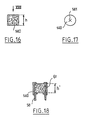
- FIG. 16 shows a block of foam 140 used as a wringing device, height h.
- this block of foam is split axially crosswise at 141 to form a passage allowing the crossing of the application element.
- the foam block may have at its upper part a conical recess 150, as illustrated in FIG. 19, for facilitate the retraction of the application element.
- the rod 151 (partially shown) supporting the application element is connected to the gripping 152 via a conical portion 153 intended to be housed in the recess 150 when the application element is in place inside the container, to limit the volume of air above the foam block.
- FIG. 20 shows a device 154 according to a ninth embodiment of the invention.
- This device 154 comprises a container formed by the assembly an upper part 155 and a lower part 156, the part upper 155 with an externally threaded neck 160 and on which screws the gripping member 161 of the applicator.
- a block of foam 157 comprising at least 5% of cells open is fixed by gluing or welding by its upper face 158 on a shoulder located at the base of the neck 160, inside a centering and sealing skirt 162, the internal diameter of which roughly corresponds to the outside diameter of the foam block 157 and whose height represents about a quarter of the height of the foam block 157.
- this element has been represented in this figure application in the form of a hollow body 163, having a cavity 164 capable of accommodating a reserve of product.
- the upper part 155 of the container is shaped so to provide a space around the foam block 157 and the skirt 162 annular 159 which allows the foam to deform axially and radially when the applicator element 163 passes.
- FIG. 21 Partly shown in FIG. 21 is a device 165 according to a tenth exemplary embodiment of the invention.
- the applicator is not shown, which can be of any type suitable for the use to be made of it.
- the device 165 has the particularity of comprising a wiping lip 166 in addition to a wiping member constituted by a foam block 167 split axially and having at least 5% of open cells.
- the device 165 comprises a cylindrical container 168 and the wiping lip 166 is produced in a tip 169 which comes insert into the upper part of the container 168.
- the wiping lip 166 partially covers the face upper 170 of foam block 167, leaving a diameter passage adapted to the nature and shape of the application element.
- the tip 169 comprises a tubular wall 171 which defines a cylindrical housing in which the foam block 167 is received.
- a retaining piece 172 having in axial section the shape general of a U, which is housed at its upper part in a annular space present between the wall 171 and the container 168 and snaps onto reliefs 173 of the wall 171.
- the piece of retainer 172 is pierced in its center for the passage of the element application.
- the tip 169 is shaped to guide the application element when it enters the container 168, and has a surface 173 converging towards the wiping lip 166.
- FIG. 22 shows a device 175 in accordance with an eleventh embodiment of the invention.
- This device includes, like the previous one, a lip spin 176 in addition to a block of foam 177 comprising at least 5% open cells.
- the wiping lip 176 is formed in a nozzle 178 which is inserted into the neck of the container.
- the wiping lip is extended above by a wall conical 179, serving as a guide during the retraction of the element application.
- the foam block 177 is hollowed out at its upper part to partially engage around the wiping lip 176.
- the presence of a wall guiding the application element towards the center of the block of foam allows when returning the applicator to avoid damage the application element, especially when the diameter outside of the foam block is relatively small.
- the application element may not be presented in the center of the foam block, where finds the axial recess or the slots allowing the passage of the foam block.
- the effort that would be required to insert the application element in the foam block could then be relatively large, especially if the foam block is weak diameter.
- the foam block which is fixed at its periphery has a rigid wall, would hardly deform into a hollow to guide the applicator element towards the center of the foam block.
- the foam block is glued or welded to the tip 169 or 178, made for example of polyethylene or polypropylene.
- the foam block can receive, prior to its attachment, an appropriate surface treatment.
- the container can be filled before the establishment of the wiper member, or after. In this last case, we can even take advantage of the porosity of the foam to achieve filling the container through it.
- the container can be offered for sale and the applicator separately, the container being in this case provided with a closure cap to be replaced by the applicator when use.
- the container sold separately then constitutes an element of refill intended to replace an empty container, with conservation of the same applicator.
- the invention makes it possible to wring so particularly satisfactory the application element and contributes to obtaining a neat makeup. If necessary, we can fix a small mirror on the outer wall of the container.
- the invention also allows, if necessary, the spinning of a application element whose maximum diameter is less than or equal to that of the applicator rod, which is not possible with the wiping members known from the prior art. Thanks to its great deformability, the foam can be applied to the rod and clean the latter so as to avoid the formation of a solid deposit likely to flake later, while spinning effective of the application element, even if the latter has a diameter greater or less than that of the rod.
- the invention also makes it possible to improve the emptying of the container insofar as the deformability of the wiper member allows to tilt the applicator rod to come with the element application, as shown in dotted lines in Figure 1, take of product on regions of the inner surface of the container inaccessible in the prior art.
- the rod the applicator is straight at rest, it is possible without leaving the frame of the invention use a curved rod, taking advantage of the fact that the dewatering member allows, thanks to its deformability, to house this in the container.
- the invention also advantageously makes it possible to use a applicator element having a cross-sectional shape not symmetrical of revolution, oval, square or other.
- the application member also constitutes a filter particularly effective in retaining possible product residues having dried and being deposited on the application element or on the applicator rod.
- the invention also makes it possible to avoid the emission of a noise of suction when passing through the wiper member, due to the porosity foam.
- the invention preferably applies to packaging and the application of a liquid or pasty product.
Description
La présente invention concerne le domaine des dispositifs de conditionnement et d'application d'un produit liquide, pâteux ou pulvérulent, notamment un produit cosmétique.The present invention relates to the field of devices for packaging and application of a liquid, pasty or powder, in particular a cosmetic product.
L'invention vise plus particulièrement un dispositif du type comportant un récipient ouvert à une extrémité, apte à contenir ledit produit, et un applicateur comportant une tige munie à une extrémité d'un élément d'application et à l'autre extrémité d'un organe de préhension, l'élément d'application étant introduit dans le récipient et retiré de ce dernier au contact d'un organe d'essorage élastiquement déformable logé dans le récipient.The invention relates more particularly to a device of the type comprising a container open at one end, capable of containing said product, and an applicator comprising a rod provided at one end an application element and at the other end of a gripping, the application element being introduced into the container and removed from the latter in contact with a wiper member elastically deformable housed in the container.
On connait par la demande de brevet français 2 285 101 un
dispositif de conditionnement et d'application de ce type, contenant
de l'ombre à paupières en poudre. Dans ce dispositif connu, l'organe
d'essorage est constitué par exemple par une mousse de caoutchouc ou
du liège, ménageant avec le fond du récipient un espace libre dans lequel
le produit est contenu librement.We know by the
Un maquillage soigné n'est possible qu'à la condition que l'essorage de l'élément d'application soit satisfaisant.Careful makeup is only possible provided that wringing of the application element is satisfactory.
Un essorage excessif de l'élément d'application oblige l'utilisateur à recharger fréquemment celui-ci en produit.Excessive wringing of the applicator element forces the user to frequently recharge it with product.
Un essorage incomplet laisse au contraire une quantité de produit en excès sur l'élément d'application, ce qui gêne le maquillage et conduit à une perte de produit. Ce dernier peut sécher sur la tige notamment et former un résidu solide, susceptible de s'écailler et de produire des fragments solides nuisant à la qualité du maquillage.On the contrary, an incomplete spin leaves a quantity of excess product on the application element, which hinders the makeup and leads to product loss. The latter can dry especially on the stem and form a solid residue capable of flaking and producing solid fragments detrimental to quality make-up.
L'élément d'application, en franchissant les organes d'essorage connus, se comporte en outre comme un piston et provoque l'émission d'un bruit de succion désagréable.The application element, crossing the organs known to spin, also behaves like a piston and causes the emission of an unpleasant suction noise.
Lorsque le produit est une poudre, le souffle d'air associé au bruit de succion risque de faire voler la poudre, ce qui bien entendu n'ect pas souhaitable.When the product is a powder, the breath of air associated with the sucking noise may cause the powder to fly, which of course is not desirable.
On connaít par le brevet US 3 146 806 un dispositif pour distribuer une préparation médicale à base de solvants hautement volatils.Known from US Patent 3,146,806 a device for dispensing a medical preparation based on highly volatile solvents.
Un tel dispositif comporte un récipient dont le col est muni d'un insert emprisonnant un bloc de mousse entre deux disques de maintien pourvus de fentes radiales.Such a device comprises a container whose neck is provided with an insert trapping a block of foam between two retaining discs provided with slits radials.
Pour prélever du produit, un coton tige est introduit dans le récipient au travers du bloc de mousse et des disques de maintien.To take the product, a cotton swab is introduced into the container at through foam block and holding discs.
Lors de l'extraction du coton tige, le bloc de mousse et les disques essorent le coton.When extracting the cotton swab, the foam block and the discs wring out the cotton.
Ce brevet antérieur décrit l'utilisation d'une mousse sans préciser si ses cellules sont ouvertes ou fermées.This prior patent describes the use of a foam without specifying whether its cells are open or closed.
De plus, l'élément servant à l'application, constitué par un coton tige, est destiné à être jeté après chaque usage et n'est donc pas logé dans le récipient lorsque ce dernier est fermé.In addition, the element used for the application, consisting of a cotton swab, is intended to be discarded after each use and is therefore not housed in the container when this last one is closed.
Enfin, le bloc de mousse est traversé par un perçage circulaire.Finally, the foam block is crossed by a circular bore.
Un tel dispositif ne convient pas pour essorer un élément d'application utilisé pour appliquer un produit cosmétique, tel qu'une brosse ou un embout en élastomère, dont l'essorage doit être de grande qualité pour conduire à un maquillage satisfaisant.Such a device is not suitable for wringing out an application element used to apply a cosmetic product, such as a brush or an elastomer tip, whose spin must be of high quality to lead to satisfactory makeup.
La présente invention a pour objet un dispositif de conditionnement et d'application amélioré. The present invention relates to a device for improved packaging and application.
Ce dispositif est caractérisé par les caractéristiques énoncées dans la revendication 1.This device is characterized by the characteristics set out in
L'utilisation d'une telle mousse présente de nombreux avantages. Dans le cas où le produit de maquillage est un liquide ou une pâte, la mousse peut s'imbiber de produit et humecter la tige de l'applicateur, empêchant ainsi la formation d'un dépôt solide susceptible de s'écailler et de générer des fragments solides pouvant nuire à la qualité du maquillage.The use of such foam has many benefits. In the case where the makeup product is a liquid or a paste, the foam can soak up the product and moisten the stem the applicator, thus preventing the formation of a solid deposit likely to flake off and generate solid fragments which may affect the quality of makeup.
Du fait de la porosité de la mousse, on autorise en outre un passage d'air à travers elle lors de la mise en place et du retrait de l'applicateur.Due to the porosity of the foam, a air passing through it during placement and removal of the applicator.
On évite ainsi l'apparition d'une dépression ou d'une surpression dans le récipient et l'émission d'un bruit de succion. Lorsque le produit est une poudre, on évite de faire voler cette dernière.This avoids the appearance of depression or overpressure in the container and the emission of a suction noise. When the product is a powder, we avoid flying this last.
Dans une réalisation particulière de l'invention, la mousse est au contact de la tige de l'applicateur lorsque ce dernier est en place sur le récipient.In a particular embodiment of the invention, the foam is in contact with the applicator rod when the latter is in place on the container.
Avantageusement, on veille à ce que la mousse ne soit pas comprimée excessivement par la tige de l'applicateur, lorsque ce dernier est logé dans le récipient, pour éviter tout risque de déformation permanente de la mousse qui pourrait nuire à la qualité de l'essorage.Advantageously, care is taken that the foam is not excessively compressed by the applicator rod, when this the latter is housed in the container, to avoid any risk of permanent deformation of the foam which could affect the quality spinning.
Pour ce faire, on peut réaliser conformément à une première variante de l'invention un évidement traversant la mousse axialement, de diamètre égal ou légèrement inférieur à celui de la tige. Dans une deuxième variante, on peut réaliser une fente traversant axialement la mousse et utiliser une tige extrêmement fine, en métal de préférence, de diamètre compris par exemple entre 0,2 et 0,5 mm.To do this, we can realize according to a first variant of the invention a recess passing axially through the foam, diameter equal to or slightly less than that of the stem. In second variant, an axially traversing slot can be produced foam and use an extremely thin metal rod preferably, of diameter for example between 0.2 and 0.5 mm.
Dans une réalisation particulière de l'invention, la mousse de l'organe d'essorage est disposée de manière à se situer au contact de la portion de tige adjacente à l'organe de préhension lorsque l'applicateur est en place sur le récipient. On évite ainsi la présence d'un volume d'air au-dessus de l'organe d'essorage lorsque l'applicateur est en place et la formation par séchage de résidus solides. In a particular embodiment of the invention, the foam the wiper member is arranged so as to be in contact with the portion of the rod adjacent to the gripping member when the applicator is in place on the container. This avoids the presence of a volume of air above the wiper member when the applicator is in place and the formation by drying of residues solid.
Dans une réalisation particulière de l'invention, la mousse est en contact permanent avec le produit contenu dans le récipient.In a particular embodiment of the invention, the foam is in permanent contact with the product contained in the container.
Dans une réalisation particulière de l'invention, la mousse est imbibée par la totalité du produit contenu dans le récipient. Alors, de préférence, la mousse occupe sensiblement la totalité de l'intérieur du récipient.In a particular embodiment of the invention, the foam is soaked with all of the product in the container. Then, preferably, the foam occupies substantially all of inside the container.
Dans une réalisation particulière de l'invention, l'organe d'essorage comporte un bloc de mousse rigidifié à sa périphérie et sur au moins une partie de sa hauteur par collage à la paroi du récipient, notamment pour l'empêcher de se comprimer lors de l'introduction de l'applicateur dans le récipient.In a particular embodiment of the invention, the organ of spinning has a rigidified block of foam at its periphery and over at least part of its height by gluing to the wall of the container, in particular to prevent it from compressing during the introduction of the applicator into the container.
Dans une réalisation particulière de l'invention, le récipient présente une forme allongée et la tige de l'applicateur est rectiligne. La largeur d'ouverture de l'embouchure du récipient est choisie de manière à éviter de souiller les bords du récipient au passage de l'applicateur et de préférence la largeur d'ouverture de l'embouchure du récipient est choisie de façon à pouvoir incliner la tige à l'intérieur du récipient d'au moins 10° par rapport à l'axe longitudinal du récipient.In a particular embodiment of the invention, the container has an elongated shape and the applicator stem is straight. The opening width of the container mouth is chosen so as to avoid soiling the edges of the container with passage of the applicator and preferably the opening width of the mouth of the container is chosen so as to be able to tilt the rod inside the container at least 10 ° from the axis longitudinal of the container.
Dans une réalisation particulière de l'invention, la tige de l'applicateur présente une portion médiane et une portion adjacente à l'élément d'application, le diamètre extérieur de ladite portion adjacente étant supérieur à celui de ladite portion médiane.In a particular embodiment of the invention, the rod the applicator has a middle portion and a portion adjacent to the application element, the outside diameter of said portion adjacent being greater than that of said middle portion.
Dans une réalisation particulière de l'invention, le dispositif comporte en outre une lèvre d'essorage.In a particular embodiment of the invention, the device further comprises a wiping lip.
De préférence, cette lèvre d'essorage est située à l'embouchure extérieure du récipient et elle est prolongée vers l'extérieur par une paroi divergeant en éloignement de la mousse.Preferably, this wiping lip is located at the outer mouth of the container and it is extended towards the exterior by a wall diverging away from the foam.
Dans une réalisation particulière de l'invention, la mousse présente un évidement conique.In a particular embodiment of the invention, the foam has a conical recess.
L'invention a encore pour objet un élément de recharge pour un dispositif de conditionnement et d'application tel que précité.The invention also relates to a recharging element for a packaging and application device as mentioned above.
D'autres caractéristiques et avantages de la présente invention ressortiront à la lecture de la description détaillée qui suit, d'exemples de réalisation non limitatifs de l'invention, et à l'examen du dessin annexé sur lequel :
- la figure 1 est une coupe schématique axiale d'un dispositif conforme à un premier exemple de réalisation de l'invention,
- la figure 2 est une vue illustrant la traversée par l'élément d'application de l'organe d'essorage du dispositif représenté sur la figure 1,
- les figures 3 à 6 illustrent différentes possibilités de réalisation de l'organe d'essorage,
- les figures 7 et 8 illustrent une variante de réalisation du dispositif représenté sur la figure 1,
- la figure 9 est une vue en coupe axiale, schématique, d'un dispositif conforme à un deuxième exemple de réalisation de l'invention,
- la figure 10 est une vue schématique en coupe axiale d'un dispositif conforme à un troisième exemple de réalisation de l'invention,
- la figure 11 est une vue schématique en coupe axiale d'un dispositif conforme à un quatrième exemple de réalisation de l'invention,
- la figure 12 est une vue schématique en coupe axiale d'un dispositif conforme à un cinquième exemple de réalisation de l'invention,
- la figure 13 est une vue schématique en coupe axiale d'un dispositif conforme à un sixième exemple de réalisation de l'invention,
- la figure 14 est une vue schématique en coupe axiale d'un dispositif conforme à un septième exemple de réalisation de l'invention, l'espace libre n'y étant pas représenté,
- la figure 15 est une vue schématique en coupe axiale partielle, d'un dispositif conforme à un huitième exemple de réalisation de l'invention,
- la figure 16 montre en élévation latérale un bloc de mousse utilisé comme organe d'essorage, à l'état non comprimé,
- la figure 17 est une vue du bloc de mousse représenté sur la figure 16, en vue de dessus, faisant apparaítre une fente en croix traversant axialement le bloc de mousse,
- la figure 18 montre le bloc de mousse représenté sur la figure 16, comprimé axialement lorsqu'il est en place dans le récipient,
- la figure 19 illustre une particularité de réalisation du bloc de mousse,
- la figure 20 est une vue schématique en coupe axiale d'un dispositif conforme à un neuvième exemple de réalisation de l'invention,
- la figure 21 est une vue schématique en coupe axiale d'un dispositif conforme à un dixième exemple de réalisation de l'invention, et
- la figure 22 est une vue schématique en coupe axiale d'un dispositif conforme à un onzième exemple de réalisation de l'invention.
- FIG. 1 is a schematic axial section of a device according to a first embodiment of the invention,
- FIG. 2 is a view illustrating the passage through the application element of the wiping member of the device shown in FIG. 1,
- FIGS. 3 to 6 illustrate different possibilities for producing the wiping member,
- FIGS. 7 and 8 illustrate an alternative embodiment of the device shown in FIG. 1,
- FIG. 9 is a schematic view in axial section of a device according to a second embodiment of the invention,
- FIG. 10 is a schematic view in axial section of a device according to a third embodiment of the invention,
- FIG. 11 is a schematic view in axial section of a device according to a fourth embodiment of the invention,
- FIG. 12 is a schematic view in axial section of a device according to a fifth embodiment of the invention,
- FIG. 13 is a schematic view in axial section of a device according to a sixth embodiment of the invention,
- FIG. 14 is a schematic view in axial section of a device according to a seventh embodiment of the invention, the free space not being shown therein,
- FIG. 15 is a schematic view in partial axial section of a device according to an eighth embodiment of the invention,
- FIG. 16 shows in side elevation a block of foam used as a wiping member, in the uncompressed state,
- FIG. 17 is a view of the foam block shown in FIG. 16, seen from above, showing a cross slot axially passing through the foam block,
- FIG. 18 shows the block of foam shown in FIG. 16, compressed axially when it is in place in the container,
- FIG. 19 illustrates a particular embodiment of the foam block,
- FIG. 20 is a schematic view in axial section of a device according to a ninth embodiment of the invention,
- FIG. 21 is a schematic view in axial section of a device according to a tenth embodiment of the invention, and
- Figure 22 is a schematic view in axial section of a device according to an eleventh embodiment of the invention.
On a représenté sur la figure 1 un dispositif 1 conforme à un
premier exemple de réalisation de l'invention.There is shown in Figure 1 a
Ce dispositif 1 comporte un récipient 2 et un applicateur 6.This
Le récipient 2 est formé d'un corps tubulaire 3 venu de
moulage par injection et d'un fond 4 fixé dans le corps 3 par
encliquetage. Ce dernier présente à sa partie supérieure un col 5
fileté extérieurement.The
Le récipient 2 contient dans l'exemple décrit un produit
cosmétique liquide P dont le solvant est l'eau, par exemple une
formule aqueuse de résine acrylique ou polyuréthane. Il peut s'agir
par exemple d'un rouge à lèvre liquide.The
L'applicateur 6 comporte un organe de préhension 7 formant
également capuchon de fermeture du récipient 2, apte à être vissé sur
le col 5, prolongé vers le bas par une tige 8 qui peut être rigide ou
souple, munie en extrémité d'un élément d'application 9 qui peut être
de tout type connu en soi, et qui n'a été représenté que très
schématiquement sur la figure 1. Dans l'exemple décrit, l'élément
d'application présente un diamètre externe supérieur à celui de la
tige.The
La tige 8 présente par exemple un diamètre compris entre 0,2
et 0,5 mm.The
L'élément d'application 9 peut présenter une section
transversale circulaire ou non, et comporter sur sa surface latérale
des reliefs, être constitué par exemple par un applicateur non
absorbant tel qu'une brosse, par une mousse floquée ou non, par un
feutre, par un pinceau, par un plastique floqué, ou par un embout
en élastomère.The
L'élément d'application peut encore être constitué par un corps creux capable de loger une réserve de produit.The application element can also be constituted by a hollow body capable of accommodating a reserve of product.
Le col 5 est épaulé intérieurement pour former un logement 10
destiné à recevoir par le dessus un bloc de mousse 11 servant
d'organe d'essorage.The
Ce bloc de mousse 11 vient en butée axialement dans le fond du
logement 10 en étant retenu dans ce dernier au moyen d'une bague de
retenue 12 encliquetée sur le col 5.This block of
La surface interne 13 du col 5 prolongeant inférieurement le
logement 10 est conique, divergeant vers le bas, et définit une
ouverture dont le diamètre est sensiblement supérieur au diamètre
externe maximum de l'élément d'application 9.The
La bague de retenue 12 définit une ouverture 14, conique
convergeant vers le bas pour faciliter la rentrée de l'élément
d'application 9 dans le récipient 2.The retaining
Le bloc de mousse 11 est dans l'exemple de réalisation de la
figure 1, cylindrique de révolution, et il est traversé par un
évidement axial 15 de section circulaire, de diamètre sensiblement
égal au diamètre externe de la tige 8, donc inférieur au diamètre
maximum de l'élément d'application 9.The
Le serrage de la bague 12 contre le fond de l'organe de
préhension 7 permet d'obtenir l'étancheité à la fermeture.The tightening of the
On remarquera à l'examen de la figure 1 que, lorsque
l'applicateur 6 est en place sur le récipient 2, il n'existe
pratiquement aucun volume d'air au dessus du bloc de mousse 11. La
tige 8 se raccorde à l'organe de préhension par une partie
tronconique 8' qui est conformée pour s'engager dans la bague 12
jusqu'au contact du bloc de mousse 11.It will be noted on examining FIG. 1 that, when
the
L'organe d'essorage peut être réalisé en une mousse d'un élastomère tel que le polyuréthane ou le polyéther notamment.The wiper member can be made of a foam of a elastomer such as polyurethane or polyether in particular.
La mousse comporte au moins 5% de cellules ouvertes, les cellules ayant un diamètre de préférence compris entre 5 µm et 3 mm.The foam contains at least 5% open cells, the cells preferably having a diameter between 5 μm and 3 mm.
La hauteur du bloc de mousse 11 est comprise par exemple entre
1,5 mm et 80 mm et de préférence comprise entre 5 et 30mm.The height of the
Le diamètre externe du bloc de mousse est par exemple compris entre 8 et 30mm, et de préférence entre 10 et 20mm.The external diameter of the foam block is for example included between 8 and 30mm, and preferably between 10 and 20mm.
La souplesse du bloc de mousse 11 lui permet de se déformer au
passage de l'élément d'application 9 pour épouser étroitement le
contour de ce dernier et obtenir un essorage efficace.The flexibility of the
On a illustré sur la figure 2 la déformation du bloc de mousse
11 lors de la rentrée ou de la sortie de l'élément d'application 9.Illustrated in Figure 2 the deformation of the
En choisissant l'évidement axial 15 avec une section de
diamètre légèrement inférieur ou égal à celui de la tige 8, l'organe
d'essorage essuie avantageusement non pas seulement l'élément
d'application 9 mais aussi la tige 8 lors de la traversée du bloc de
mousse 11 et l'on évite ainsi que du produit ne sèche sur la tige 8
en formant un dépôt solide, susceptible de s'écailler ultérieurement
et de polluer le produit présent dans le récipient.By choosing the
Grâce à sa porosité, l'organe d'essorage peut rester imbibé de produit tant qu'il en reste dans le récipient. Ainsi, dans le cas où le produit utilisé est une formule aqueuse d'une résine acrylique ou polyuréthane, l'organe d'essorage conserve suffisamment d'humidité pour empêcher la réticulation de la résine en son sein et humecte la tige et l'élément d'application à leur passage.Thanks to its porosity, the wiper member can remain soaked in product while it remains in the container. So, in case the product used is an aqueous formula of an acrylic resin or polyurethane, the wiper keeps enough moisture to prevent crosslinking of the resin within it and moistens the rod and the applicator element as they pass.
L'organe d'essorage peut ainsi exercer à la fois :
- une action mécanique d'essorage et de nettoyage de l'élément d'application en enserrant ce dernier et en retenant par raclage le produit en excès, et les éventuels résidus solides résultant du séchage du produit lorsque celui-ci est un liquide ou une pâte,
- une action d'absorbtion par capillarité, et
- une action d'absorbtion par aspiration lorsque la mousse reprend sa forme initiale après avoir été comprimée localement par le passage de l'élément d'application,
- éventuellement une action d'imprégnation en produit lorsque l'élément d'application est moins chargé que ne l'est l'organe d'essorage.
- a mechanical action of wringing and cleaning the application element by enclosing the latter and retaining by scraping the excess product, and any solid residues resulting from the drying of the product when the latter is a liquid or a paste ,
- an action of absorption by capillarity, and
- an absorption action by suction when the foam returns to its initial shape after being compressed locally by the passage of the application element,
- possibly a product impregnation action when the application element is less loaded than is the wiper member.
L'exemple de réalisation des figures 1 et 2 n'est nullement limitatif.The embodiment of Figures 1 and 2 is by no means limiting.
Le bloc de mousse 11 décrit en référence aux figures 1 et 2
peut ainsi être remplacé par un bloc de mousse 16 représenté sur la
figure 3, qui n'est pas traversé par un évidement axial mais est
incisé axialement en croix pour former des fentes 17 le traversant de
part en part et pouvant s'écarter au passage de l'élément
d'application 9.The
Dans une variante non représentée, le bloc de mousse peut être à la fois traversé axialement par un évidement central et fendu.In a variant not shown, the foam block can be both axially crossed by a central recess and split.
Lors du retrait de l'applicateur ou de son positionnement sur le récipient, l'élément d'application est susceptible de comprimer axialement la mousse avant de pénétrer à l'intérieur de celle-ci, en particulier si l'élément d'application présente une face frontale aplatie ou concave vers l'extérieur.When removing the applicator or positioning it on the container, the application element is likely to compress axially the foam before penetrating inside thereof, in particularly if the application element has a front face flattened or concave outward.
Le bloc de mousse ainsi comprimé tend à devenir plus compact au centre, opposant davantage de résistance à la pénétration de l'élément d'application.The block of foam thus compressed tends to become more compact in the center, offering more resistance to the penetration of the application element.
Pour éviter que le bloc de mousse ne se contracte sur lui-même
et rende difficile la rentrée ou l'extraction de l'élément
d'application, on rigidifie avantageusement sur tout ou partie de sa
hauteur le bloc de mousse à sa périphérie, par exemple en l'enduisant
d'une résine durcissable formant après polymérisation une peau 18
empêchant le bloc de mousse de s'écraser sur lui-même.To prevent the foam block from contracting on itself
and makes it difficult to re-enter or extract the element
of application, advantageously stiffens over all or part of its
height the foam block at its periphery, for example by coating it
of a curable resin forming, after polymerization, a
En variante ou additionnellement, on peut coller ou souder le bloc de mousse à sa périphérie à la surface interne du col du récipient.As a variant or additionally, it is possible to glue or weld the block of foam at its periphery on the inner surface of the neck of the container.
On a représenté sur la figure 4 une variante dans laquelle
l'organe d'essorage est formé par la réunion de deux demi-cylindres
pleins 19 en mousse, maintenus l'un contre l'autre par le col 5 du
récipient et définissant entre eux une fente 20 pouvant s'ouvrir au
passage de l'élément d'application 9.FIG. 4 shows a variant in which
the wiper member is formed by the union of two half-cylinders
full 19 of foam, held against each other by the
En variante encore, l'organe d'essorage peut être réalisé par
l'enroulement d'une bande de mousse 21 sur elle-même, définissant un
évidement central 22 pour le passage de l'élément d'application 9.In another variant, the wiping member can be produced by
the winding of a strip of
L'organe d'essorage peut également être réalisé par la superposition de plusieurs rondelles en mousses de natures différentes.The wiper member can also be produced by the superimposition of several nature foam washers different.
On a représenté à titre d'exemple non limitatif sur la figure
6 un organe d'essorage 23 constitué par la superposition de trois
rondelles 25, 26 et 27 réalisées dans des mousses présentant des
densités de cellules croissantes à mesure que l'on se rapproche de la
sortie du récipient, l'ensemble étant traversé par un évidement axial
24 pour le passage de l'élément d'application 9.There is shown by way of nonlimiting example in the figure
6 a
L'organe d'essorage peut également comporter un bloc de mousse
11 et un disque rigide 28 servant à l'essorage du bloc de mousse 11,
comme représenté sur les figures 7 et 8.The wiper member may also include a
Le disque d'essorage 28 est disposé sous le bloc du mousse 11
en étant retenu dans le col 5 par l'épaulement délimitant
inférieurement le logement 10. Il est traversé en son centre par un
perçage 30 pour le passage de l'élément d'application 9. Ce dernier
est surmonté dans l'exemple considéré par un bourrelet élastique 29
formant saillie sur la tige 8 et destiné à venir en appui contre le
disque 28 lorsque l'applicateur 6 est retiré du récipient.The
Le diamètre du perçage 30 est inférieur au diamètre maximum du
bourrelet 29 de sorte que le disque 28 est entraíné vers le haut par
l'applicateur pour tasser axialement le bloc de mousse 11 qui est
ainsi essoré.The diameter of the
Après compression axiale du bloc de mousse 11, le bourrelet 29
peut franchir par déformation élastique le perçage 30.After axial compression of the
Le disque 28 est traversé par des orifices 31 qui permettent
l'écoulement vers l'intérieur du récipient du produit en excès qui
quitte le bloc de mousse 11 à l'état comprimé.The
La capacité d'absorbtion du bloc de mousse 11 au passage de
l'élément d'application est alors augmentée.The absorbency of the
La présence du bourrelet 29 permet d'avoir le cas échéant un
élément d'application très souple, qui ne pourrait à lui-seul du fait
de sa souplesse entraíner vers le haut le disque 28.The presence of the
Bien que cela ne soit pas représenté sur les figures, on peut sans sortir du cadre de l'invention disposer un organe d'essorage supplémentaire connu en lui-même à l'intérieur du récipient, destiné à être traversé avant le bloc de mousse par l'élément d'application lors de sa sortie du récipient.Although not shown in the figures, one can without departing from the scope of the invention have a wiping member additional known in itself inside the container, intended to be crossed before the foam block by the application element when it comes out of the container.
L'organe d'essorage peut être retenu de nombreuses manières dans le récipient.The wiper can be retained in many ways in the container.
Comme évoqué précédemment, le bloc de mousse peut être simplement collé ou soudé à sa périphérie à la paroi du récipient. As mentioned above, the foam block can be simply glued or welded at its periphery to the wall of the container.
On a représenté sur les figures 9 à 12 diverses autres possibilités de maintien de l'organe d'essorage, pouvant se combiner le cas échéant avec le collage ou le soudage du bloc de mousse au récipient.Various other figures are shown in Figures 9 to 12 possibilities of holding the wiper member, which can be combined if necessary with bonding or welding the foam block to the container.
On a représenté sur la figure 9 un dispositif 32 qui comporte
un récipient 33 réalisé par une technique d'injection soufflage et un
applicateur non représenté, identique à l'applicateur de l'exemple de
réalisation de la figure 1.FIG. 9 shows a
Le récipient 33 présente un col 34, dans lequel est encliqueté
un manchon 35 épaulé intérieurement pour former un logement 36
destiné à recevoir par le bas un bloc de mousse 37, retenu dans le
manchon 35 par une bague 38 encliquetée à l'extrémité inférieure du
manchon 35.The
Le bloc de mousse 37 et la bague de maintien 38 sont mis en
place sur le manchon 35 avant l'insertion de ce dernier dans le col
34 du récipient 33.The
On a représenté sur la figure 10 un dispositif 39 comportant
un récipient 40 et un applicateur 41.FIG. 10 shows a
Le récipient 40 comporte un corps en deux parties supérieure
42 et inférieure 43 reliées par une paroi annulaire amincie 44,
repliée vers l'intérieur du récipient et définissant dans celui-ci un
rétrécissement de section sur lequel s'appuie l'extrémité inférieure
d'un bloc de mousse 45 servant d'organe d'essorage. Le bloc de mousse
45 est retenu à son extrémité supérieure par une bague 46 encliquetée
à l'extrémité libre de la partie supérieure 42 du récipient 40.The
L'applicateur 41 comporte une tige 47, munie à une extrémité
d'un organe de préhension 48 apte à s'emboíter sur un col formé sur
le dessus de la bague 46, et à l'autre extrémité, d'un organe
d'application 49.The
L'organe de préhension 48 comporte également un arceau 50
pivotant autour d'un tourillon 51 et pouvant venir en appui dans une
première position sur la face externe du fond 52 du récipient pour
retenir l'applicateur 41 sur la bague 46 et fermer le récipient 40
et, dans une deuxième position, diamétralement à l'opposé de la
première, servir de poignée facilitant l'utilisation de l'applicateur.The gripping
La paroi 44 présente une certaine flexibilité qui permet de
rapprocher élastiquemeht les parties 42 et 43 pour mettre l'arceau 50
en position de fermeture du récipient. Lorsque le récipient est
relâché, la paroi 44 tend par élasticité à reprendre sa forme
initiale et à écarter les parties supérieure 42 et inférieure 43,
cette dernière exerçant alors une certaine pression de contact sur
l'arceau 50, qui est ainsi empêché de pivoter librement.The
La bague 46 présente une lèvre supérieure d'étancheité qui
s'ajuste à la fermeture dans une gorge inférieure de l'organe de
préhension 48.The
On a représenté sur la figure 11 un dispositif 53 conforme à
un quatrième exemple de réalisation de l'invention. Ce dispositif 53
comporte un récipient 54 à double paroi et un applicateur 55.FIG. 11 shows a
Le récipient 54 est formé par l'assemblage d'une partie
inférieure 56 et d'une partie supérieure 57.The
La partie inférieure 56 comporte une paroi tubulaire centrale
58, fermée à son extrémité inférieure par un fond 59 rapporté, et
prolongée radialement à l'extérieur vers le haut à partir de son
extrémité inférieure par une jupe externe 60. La paroi tubulaire
centrale 58 présente à son extrémité supérieure un rebord interne 63.The
La partie supérieure 57 comporte une paroi tubulaire centrale
61, prolongée à l'extérieur vers le bas par une jupe externe 62,
conformée pour s'encliqueter à son extrémité inférieure dans la jupe
externe 60 de manière à obtenir une continuité de la surface externe
du récipient. La paroi tubulaire centrale 61 est munie à son
extrémité supérieure d'un rebord interne 65.The
La paroi 58 s'engage de façon étanche dans la paroi 61 et
contient le produit cosmétique à distribuer.The
Le rebord 63 sert d'appui à l'extrémité inférieure d'un bloc
de mousse 64 servant d'organe d'essorage, occupant sensiblement tout
le volume à l'intérieur de la paroi tubulaire centrale 61 entre les
rebords 63 et 65. Le bloc de mousse 64 est ainsi retenu dans la
partie supérieure 57 par la partie inférieure 56.The
L'applicateur 55 comporte une tige 67 munie à une extrémité
d'un élément d'application 68 et solidaire à l'autre extrémité d'un
organe de préhension 69.The
Un arceau 70 est articulé sur la partie supérieure 57 du
récipient 54 pour retenir l'organe de préhension 69 plaqué sur le
rebord 65 en l'absence d'utilisation de l'applicateur et fermer ainsi
de façon étanche le récipient 54.A
La jupe externe 62 se raccorde sur la paroi tubulaire centrale
61 par une portion annulaire orientée sensiblement
perpendiculairement à l'axe longitudinal de la tige 67, et l'arceau
70 pivote sur cette portion annulaire au moyen de charnières 71.
L'arceau 70 présente, à son sommet, un bossage 72 dirigé vers
l'intérieur et apte à s'engager dans un creux 73 formé au sommet de
l'organe de préhension 69, pour maintenir ce dernier plaqué sur le
rebord 65.The
Le rebord 65 définit une ouverture 66 conique convergeant vers
l'intérieur du récipient.The
Lorsque le récipient est réalisé dans une matière plastique
transparente, la double paroi 54 donne l'impression à l'utilisateur
que le récipient présente une paroi épaisse, réalisée par exemple
dans un verre épais, ce qui ajoute à l'esthétique du récipient.When the container is made of a plastic material
transparent, the
On a représenté sur 1a figure 12 un dispositif 87 conforme à
un cinquième exemple de réalisation de l'invention.FIG. 12 shows a
Ce dispositif comporte un récipient 88 et un applicateur 89.This device comprises a
Le récipient 88 est formé par l'assemblage d'une partie
inférieure 90 et d'une partie supérieure 91.The
La partie inférieure 90 présente une paroi tubulaire centrale
92 fermée inférieurement par un fond rapporté 93 et prolongée
supérieurement, à partir de son extrémité inférieure, par une jupe
externe 94 concave vers le haut.The
La paroi tubulaire 92 est épaulée à sa partie supérieure et se
termine par un rebord 95 formant radialement saillie vers
l'intérieur.The
La partie supérieure 91 du récipient 88 comporte une paroi
tubulaire centrale 96 prolongée radialement vers l'extérieur, au
voisinage de son extrémité supérieure, par une jupe externe 97 qui
est arrondie vers le bas et sur la surface interne de laquelle
s'encliquette la jupe externe 94 de la partie inférieure 90. La paroi
centrale tubulaire 96 s'engage alors de façon étanche sur la partie
supérieure de la paroi centrale tubulaire 92. The
Un arceau 98, venu de moulage avec la partie supérieure 91 du
récipient, s'articule sur la jupe externe 97 au moyen de ponts de
matière 99 formant charnières.A
La paroi centrale tubulaire 96 présente, au niveau du
raccordement de la jupe externe 97, un décrochement 100 vers
l'intérieur, prolongé vers le haut par un col 101.The tubular
L'applicateur 89 comporte un organe de préhension 102,
prolongé vers le bas par une tige 103 munie à son extrémité
inférieure d'un élément d'application 104.The
L'organe de préhension 102 est formé par l'assemblage d'un
corps externe 105, de forme ogivale, ouvert à son extrémité
inférieure et d'une partie interne 106 emmanchée dans le corps
externe 105 et présentant un logement creux 107 dans lequel est
retenue une tête sphérique 108 formée à l'extrémité supérieure de la
tige 103, de manière à constituer une rotule.The gripping
En position de fermeture du récipient 88, le corps externe 105
de l'organe de préhension 102 s'ajuste sur le col 101.In the closed position of the
L'étancheité à la fermeture est obtenue par le serrage de la
partie interne 106 contre la tranche d'extrémité supérieure du col
101.The seal at closing is obtained by tightening the
La tige 103 de l'applicateur 89 s'élargit à son extrémité
inférieure 109 pour former un logement servant à la fixation de
l'élément d'application 104, constitué dans l'exemple décrit par une
pointe en feutre.The
Un bloc de mousse 110 est logé à l'intérieur de la paroi
tubulaire centrale 96, en étant retenu axialement à son extrémité
inférieure par le rebord interne 95 et à son extrémité supérieure par
le décrochement 100.A block of
Le bloc de mousse 110 est revêtu à sa périphérie d'une peau
111 relativement rigide destinée à éviter son écrasement au passage
de la partie élargie 109 de la tige 103, à l'instar de ce qui a été
décrit précédemment en référence à la figure 3.The
Dans les exemples de réalisation qui viennent d'être décrits, le bloc de mousse servant d'organe d'essorage n'occupe que la partie supérieure de l'intérieur du récipient. In the exemplary embodiments which have just been described, the foam block serving as a wringing device occupies only the part inside the container.
On va maintenant décrire en référence aux figures 13 et 14 deux exemples de réalisation de l'invention dans lesquels le bloc de mousse occupe la quasi totalité du volume intérieur du récipient.We will now describe with reference to Figures 13 and 14 two embodiments of the invention in which the block of foam occupies almost the entire interior volume of the container.
On a représenté sur la figure 13 un dispositif 74 conforme à
un sixième exemple de réalisation de l'invention. Ce dispositif 74
comporte un récipient 75 et un applicateur 76.FIG. 13 shows a
Le récipient 75 comporte une partie supérieure 79 et une
partie inférieure présentant une paroi tubulaire centrale 77 fermée à
son extrémité inférieure et prolongée à partir de cette dernière vers
le haut et vers l'extérieur par une jupe externe 78.The
La partie supérieure 79 présente une paroi tubulaire centrale
qui est fixée par encliquetage dans la paroi tubulaire 77 et une jupe
externe 80 qui s'étend vers le bas autour de la paroi tubulaire 77 et
vient s'appliquer contre le bord libre de la jupe externe 78.The
Des encoches demi-circulaires sont formées sur les bords
venant en contact des jupes externes 78 et 80 pour constituer, après
assemblage des parties inférieure et supérieure du récipient, des
perçages pour le montage à rotation des extrémités d'un arceau 81.Semicircular notches are formed on the edges
coming into contact with the
L'applicateur 76 comporte une tige 82 munie à une extrémité
d'un élément d'application 83 et solidaire à l'autre extrémité d'un
organe de préhension 84, qui est maintenu en place sur la partie
supérieure 79, en l'absence d'utilisation de l'applicateur, par
l'arceau 81. La partie supérieure 79 est traversée à son sommet par
une ouverture 85 dont le diamètre est supérieur au diamètre maximum
de l'élément d'application 83.The
L'intérieur du récipient 74 est occupé par un bloc
de mousse 86 qui est évidé axialement ou incisé pour loger la tige 82
et l'élément d'application 83 lorsque l'applicateur 76 est en place
sur le récipient 74. L'espace libre n'est pas représenté à la fig. 14.The interior of the
Le produit à distribuer imbibe à saturation au moins la partie
inférieure du bloc de mousse 86 au contact de l'élément d'application
83 lorsque l'applicateur ferme le récipient.The product to be distributed soaks at least part of the saturation
bottom of
La partie supérieure du bloc de mousse 86 joue alors le rôle
d'organe d'essorage.The upper part of the
L'organe de préhension 84 présente une jupe externe qui
s'applique à la fermeture du récipient sur la partie supérieure de ce
dernier. The gripping
L'étancheité à la fermeture est ainsi obtenue à la fois par
l'application contre la face supérieure du récipient bordant
l'ouverture 85 de la partie centrale de l'organe de préhension sur
laquelle se raccorde la tige 82 et par la jupe externe précitée.The seal at closing is thus obtained both by
the application against the upper face of the bordering container
the
On a représenté sur la figure 14 un dispositif 112 comportant
un récipient 113 et un applicateur 114.FIG. 14 shows a
Le récipient 113 présente une paroi tubulaire centrale 115
fermée à son extrémité inférieure par un fond 116, rapporté.The
La paroi tubulaire centrale 115 présente à son extrémité
supérieure un décrochement 117, dirigé vers l'intérieur, prolongé
vers le haut par un col 118.The central
La paroi tubulaire centrale 115 est prolongée radialement vers
l'extérieur, à hauteur du décrochement 117, par une jupe externe 119
recourbée vers le bas.The central
Un habillage tubulaire 120, ayant une forme concave vers le
haut, est encliqueté à l'extrémité inférieure de la jupe externe 119.A tubular covering 120, having a concave shape towards the
top, is snapped onto the lower end of the
L'habillage 120 est traversé à son extrémité inférieure par un
perçage 121, dans lequel vient s'ajuster l'extrémité inférieure de la
paroi tubulaire 115, la face externe du fond 116 venant à
affleurement de la surface annulaire inférieure de l'habillage 120
bordant extérieurement ledit perçage.The covering 120 is crossed at its lower end by a
Un arceau de retenue 122 est articulé sur la jupe 119, à
l'instar de l'arceau 98 décrit précédemment.A retaining
L'applicateur 114 comporte un organe de préhension prolongé
inférieurement par une tige 123.The
L'organe de préhension comporte un corps externe 124 identique
à celui, référencé 105, de l'organe de préhension 89 précédemment
décrit et une partie interne 125 servant à la fixation de la tige 123
et à assurer une fermeture étanche du récipient en l'absence
d'utilisation.The gripping member has an identical
La partie interne 125 ménage avec le corps externe une gorge
annulaire s'ouvrant vers le bas et dans laquelle s'engage le col 118
lorsque l'organe de préhension est en place sur le récipient.The
La partie interne 125 est légèrement conique à son extrémité
inférieure, s'élargissant vers le haut, de manière à s'engager
facilement dans l'ouverture du récipient tout en pouvant s'appliquer
étroitement, au terme de l'insertion sur le col 118, sur la surface
interne de ce dernier pour obtenir une fermeture étanche du récipient.The
La partie interne 125 est délimitée inférieurement par une
paroi plane 126, occupant presque la totalité de la section interne
du col 118 et sur laquelle se raccorde la tige 123. Cette dernière
est munie inférieurement d'une partie élargie 127 servant à la
fixation de l'élément d'application 128, de façon identique à ce qui
a été décrit en référence à la figure 12.The
Le volume interne de la paroi tubulaire centrale 115 est
occupé par un bloc de mousse 129, à l'instar
de l'exemple de réalisation de la figure 13.The internal volume of the central
Ce bloc de mousse 129 ménage avec le fond du récipient un espace libre non
représenté et peut être évidé axialement pour loger la
tige et l'élément d'application ou être simplement incisé axialement.This block of
Il est avantageux, lorsque l'applicateur est en place sur le
récipient, que la paroi 126 vienne à affleurement de la face
supérieure du bloc de mousse, car on évite de cette façon le séchage
de la tige 123 sur toute sa longueur et la formation de tout dépôt
solide sur cette dernière, qui serait susceptible de s'écailler par
la suite.It is advantageous, when the applicator is in place on the
container, that the
On a représenté sur la figure 15 un dispositif 130 conforme à
un huitième exemple de réalisation de l'invention.FIG. 15 shows a
Ce dispositif 130 est identique pour sa partie inférieure à
celui représenté sur la figure 14, et comporte un récipient qui
diffère du récipient précédent 113 par l'absence d'arceau 122,
remplacé par une jupe filetée extérieurement 131.This
Le dispositif 130 comporte un applicateur 132 constitué d'un
organe de préhension et d'une tige d'applicateur 123 dont la partie
inférieure est identique à celle décrite en référence à la figure 14.The
La tige 123 se raccorde sur une partie interne 133 fixée à
l'extrémité inférieure d'une jupe tubulaire interne 134 de l'organe
de préhension.The
Une collerette externe 135 limite l'insertion de la partie
interne 133 dans la jupe 134.An
L'organe de préhension comporte une jupe tubulaire externe 136
coaxiale à la jupe interne 134 et filetée intérieurement pour se
visser sur la jupe 131 du récipient. The gripping member comprises an external
Lorsque l'organe de préhension est vissé sur le récipient, la
collerette 135 est pressée contre la tranche supérieure du col 118
pour l'obtention d'une fermeture étanche du récipient.When the gripping member is screwed onto the container, the
Il est avantageux que le filetage de la jupe 131 soit éloigné
du col 118 car l'on évite ainsi qu'un dépôt de produit sur le col 118
gêne la fermeture du récipient en souillant les filetages des jupes
131 et 136, l'espace ménagé entre l'ouverture du récipient et les
filetages pouvant loger d'éventuels débordements de produit.It is advantageous that the thread of the
On a représenté sur la figure 16 un bloc de mousse 140 utilisé
comme organe d'essorage, de hauteur h.FIG. 16 shows a block of
Comme on peut le voir à l'examen de la figure 17, ce bloc de mousse est fendu axialement en croix en 141 pour former un passage permettant la traversée de l'élément d'application.As can be seen on examining Figure 17, this block of foam is split axially crosswise at 141 to form a passage allowing the crossing of the application element.
En fonction du type d'élément d'application utilisé, ou de la nature du produit contenu dans le récipient, il peut être souhaitable d'exercer une force radiale plus ou moins grande sur l'élément d'application à son passage au travers de l'organe d'essorage.Depending on the type of application element used, or the nature of the product in the container, it may be desirable to exert a greater or lesser radial force on the element of application when it passes through the wiping member.
On peut alors choisir des mousses à structure de cellules ouvertes présentant des duretés plus ou moins grandes.We can then choose cell structure foams open with varying degrees of hardness.
On peut également, avantageusement, n'utiliser qu'un seul type de mousse à structure de cellules ouvertes, et comprimer axialement la mousse plus ou moins selon la friction que l'on souhaite exercer sur l'élément d'application.It is also advantageously possible to use only one type open cell foam, and compress axially the foam more or less depending on the friction that one wishes to exert on the application element.
Ainsi, comme illustré par la figure 18, si l'on comprime
axialement le bloc de mousse 140 représenté sur la figure 16 en le
plaçant dans un logement du récipient tel que par exemple le logement
constitué par l'assemblage des parois 58 et 61 du mode de réalisation
de la figure 11, on augmente la densité de la mousse et par
conséquent les forces radiales exercées sur l'élément d'application.
En jouant sur le degré d'enfoncement de la paroi 58 dans la paroi 61,
on peut ajuster la hauteur h' à la valeur conférant à la mousse la
densité voulue.So, as illustrated in figure 18, if we compress
axially the block of
Le bloc de mousse peut présenter à sa partie supérieure un
évidement conique 150, comme illustré sur la figure 19, pour
faciliter la rentrée de l'élément d'application.The foam block may have at its upper part a
De préférence, la tige 151 (représentée partiellement)
supportant l'élément d'application se raccorde à l'organe de
préhension 152 par l'intermédiaire d'une portion conique 153 destinée
à se loger dans l'évidement 150 lorsque l'élément d'application est
en place à l'intérieur du récipient, pour limiter le volume d'air
au-dessus du bloc de mousse.Preferably, the rod 151 (partially shown)
supporting the application element is connected to the
gripping 152 via a
On a représenté sur la figure 20, un dispositif 154 conforme à
un neuvième exemple de réalisation de l'invention.FIG. 20 shows a
Ce dispositif 154 comporte un récipient formé par l'assemblage
d'une partie supérieure 155 et d'une partie inférieure 156, la partie
supérieure 155 comportant un col 160 fileté extérieurment et sur
lequel se visse l'organe de préhension 161 de l'applicateur.This
Un bloc de mousse 157 comportant au moins 5 % de cellules
ouvertes est fixé par collage ou soudage par sa face supérieure 158
sur un épaulement situé à la base du col 160, à l'intérieur d'une
jupe de centrage et d'étanchéité 162, dont le diamètre intérieur
correspond sensiblement au diamètre extérieur du bloc de mousse 157
et dont la hauteur représente le quart à peu près de la hauteur du
bloc de mousse 157.A block of
A titre d'exemple, on a représenté sur cette figure l'élément
d'application sous la forme d'un corps creux 163, présentant une
cavité 164 apte à loger une réserve de produit.By way of example, this element has been represented in this figure
application in the form of a
La partie supérieure 155 du récipient est conformée de manière
à ménager, autour du bloc de mousse 157 et de la jupe 162, un espace
annulaire 159 qui permet à la mousse de se déformer axialement et
radialement au passage de l'élément d'application 163.The
On a représenté partiellement sur la figure 21 un dispositif
165 conforme à un dixième exemple de réalisation de l'invention.Partly shown in FIG. 21 is a
L'applicateur n'est pas représenté, pouvant être de tout type adapté à l'usage qui doit en être fait.The applicator is not shown, which can be of any type suitable for the use to be made of it.
Le dispositif 165 présente la particularité de comporter une
lèvre d'essorage 166 en plus d'un organe d'essorage constitué par un
bloc de mousse 167 fendu axialement et présentant au moins 5% de
cellules ouvertes.The
Le dispositif 165 comporte un récipient cylindrique 168 et la
lèvre d'essorage 166 est réalisée dans un embout 169 qui vient
s'insérer dans la partie supérieure du récipient 168. The
La lèvre d'essorage 166 couvre partiellement la face
supérieure 170 du bloc de mousse 167, laissant un passage de diamètre
adapté à la nature et à la forme de l'élément d'application.The wiping
L'embout 169 comporte une paroi tubulaire 171 qui définit un
logement cylindrique dans lequel est reçu le bloc de mousse 167.The
Ce dernier est maintenu en place à l'intérieur dudit logement
par une pièce de retenue 172 présentant en section axiale la forme
générale d'un U, qui vient se loger à sa partie supérieure dans un
espace annulaire présent entre la paroi 171 et le récipient 168 et
s'encliquette sur des reliefs 173 de la paroi 171. La pièce de
retenue 172 est percée en son centre pour le passage de l'élément
d'application.The latter is held in place inside said housing
by a retaining
L'embout 169 est conformé pour guider l'élément d'appplication
à sa rentrée dans le récipient 168, et présente une surface 173
convergeant vers la lèvre d'essorage 166.The
On a représenté sur la figure 22 un dispositif 175 conforme à
un onzième exemple de réalisation de l'invention.FIG. 22 shows a
Ce dispositif comporte, comme le précédent, une lèvre
d'essorage 176 en plus d'un bloc de mousse 177 comportant au moins
5 % de cellules ouvertes.This device includes, like the previous one, a
La lèvre d'essorage 176 est formée dans un embout 178 qui est
inséré dans le col du récipient.The wiping
La lèvre d'essorage est prolongée supérieurement par une paroi conique 179, servant de guide lors de la rentrée de l'élément d'application.The wiping lip is extended above by a wall conical 179, serving as a guide during the retraction of the element application.
Le bloc de mousse 177 est évidé à sa partie supérieure pour
s'engager partiellement autour de la lèvre d'essorage 176.The
Comme dans la réalisation précédente, la présence d'une paroi de guidage de l'élément d'application vers le centre du bloc de mousse permet lors du retour de l'applicateur d'éviter d'endommager l'élément d'application, en particulier lorsque le diamètre extérieur du bloc de mousse est relativement faible.As in the previous embodiment, the presence of a wall guiding the application element towards the center of the block of foam allows when returning the applicator to avoid damage the application element, especially when the diameter outside of the foam block is relatively small.
En effet, en l'absence de ce guidage, l'élément d'application risquerait de ne pas être présenté au centre du bloc de mousse, où se trouve l'évidement axial ou la les fentes permettant la traversée du bloc de mousse. L'effort qu'il y aurait à exercer pour insérer l'élément d'application dans le bloc de mousse pourrait être alors relativement important, notamment si le bloc de mousse est de faible diamètre.Indeed, in the absence of this guidance, the application element may not be presented in the center of the foam block, where finds the axial recess or the slots allowing the passage of the foam block. The effort that would be required to insert the application element in the foam block could then be relatively large, especially if the foam block is weak diameter.
Dans ce cas, le bloc de mousse, qui est fixé à sa périphérie a une paroi rigide, se déformerait difficilement en creux pour guider l'élément d'application vers le centre du bloc de mousse.In this case, the foam block, which is fixed at its periphery has a rigid wall, would hardly deform into a hollow to guide the applicator element towards the center of the foam block.
Dans les deux exemples de réalisation décrits en référence aux
figures 21 et 22, le bloc de mousse est collé ou soudé sur l'embout
169 ou 178, réalisé par exemple en polyéthylène ou en polypropylène.In the two exemplary embodiments described with reference to
Figures 21 and 22, the foam block is glued or welded to the
Le bloc de mousse peut recevoir, préalablement à sa fixation, un traitement de surface approprié.The foam block can receive, prior to its attachment, an appropriate surface treatment.
Dans les exemples décrits, le récipient peut être rempli avant la mise en place de l'organe d'essorage, ou après. Dans ce dernier cas, on peut même profiter de la porosité de la mousse pour réaliser le remplissage du récipient au travers de celle-ci.In the examples described, the container can be filled before the establishment of the wiper member, or after. In this last case, we can even take advantage of the porosity of the foam to achieve filling the container through it.
Les dispositifs qui viennent d'être décrits sont avantageusement commercialisés avec l'applicateur en place sur le récipient.The devices which have just been described are advantageously sold with the applicator in place on the container.
Toutefois, on peut offrir à la vente le récipient et l'applicateur séparément, le récipient étant dans ce cas muni d'une capsule de fermeture à remplacer par l'applicateur lors de l'utilisation.However, the container can be offered for sale and the applicator separately, the container being in this case provided with a closure cap to be replaced by the applicator when use.
Le récipient vendu séparément constitue alors un élément de recharge destiné à remplacer un récipient vide, avec conservation du même applicateur.The container sold separately then constitutes an element of refill intended to replace an empty container, with conservation of the same applicator.
Finalement, l'invention permet d'essorer de façon particulièrement satisfaisante l'élément d'application et contribue à l'obtention d'un maquillage soigné. Au besoin, on peut fixer un petit miroir sur la paroi externe du récipient.Finally, the invention makes it possible to wring so particularly satisfactory the application element and contributes to obtaining a neat makeup. If necessary, we can fix a small mirror on the outer wall of the container.
L'invention permet en outre le cas échéant l'essorage d'un élément d'application dont le diamètre maximum est inférieur ou égal à celui de la tige de l'applicateur, ce qui n'est pas possible avec les organes d'essorage connus de l'art antérieur. Grâce à sa grande déformabilité, la mousse peut s'appliquer sur la tige et nettoyer cette dernière de façon à éviter la formation d'un dépôt solide susceptible de s'écailler par la suite, tout en réalisant un essorage efficace de l'élément d'application, même si ce dernier présente un diamètre supérieur ou inférieur à celui de la tige. The invention also allows, if necessary, the spinning of a application element whose maximum diameter is less than or equal to that of the applicator rod, which is not possible with the wiping members known from the prior art. Thanks to its great deformability, the foam can be applied to the rod and clean the latter so as to avoid the formation of a solid deposit likely to flake later, while spinning effective of the application element, even if the latter has a diameter greater or less than that of the rod.
L'invention permet également d'améliorer le vidage du récipient dans la mesure où la déformabilité de l'organe d'essorage permet d'incliner la tige de l'applicateur pour venir avec l'élément d'application, comme illustré en pointillés sur la figure 1, prélever du produit sur des régions de la surface interne du récipient inaccessibles dans l'art antérieur.The invention also makes it possible to improve the emptying of the container insofar as the deformability of the wiper member allows to tilt the applicator rod to come with the element application, as shown in dotted lines in Figure 1, take of product on regions of the inner surface of the container inaccessible in the prior art.
Bien que dans tous les exemples décrits la tige de l'applicateur soit rectiligne au repos, on peut sans sortir du cadre de l'invention utiliser une tige courbe, en profitant du fait que l'organe d'essorage permet, grâce à sa déformabilité, de loger celle-ci dans le récipient.Although in all the examples described the rod the applicator is straight at rest, it is possible without leaving the frame of the invention use a curved rod, taking advantage of the fact that the dewatering member allows, thanks to its deformability, to house this in the container.
L'invention permet encore avantageusement d'utiliser un élément d'application présentant en section transversale une forme non symétrique de révolution, ovale, carrée ou autre.The invention also advantageously makes it possible to use a applicator element having a cross-sectional shape not symmetrical of revolution, oval, square or other.
L'organe d'application constitue en outre un filtre particulièrement efficace pour retenir d'éventuels résidus de produit ayant séché et s'étant déposés sur l'élément d'application ou sur la tige de l'applicateur.The application member also constitutes a filter particularly effective in retaining possible product residues having dried and being deposited on the application element or on the applicator rod.
L'invention permet aussi d'éviter l'émission d'un bruit de succion à la traversée de l'organe d'essorage, du fait de la porosité de la mousse.The invention also makes it possible to avoid the emission of a noise of suction when passing through the wiper member, due to the porosity foam.
L'invention s'applique de préférence au conditionnement et à l'application d'un produit liquide ou pâteux.The invention preferably applies to packaging and the application of a liquid or pasty product.
Toutefois, on ne sort pas du cadre de l'invention lorsque le produit est pulvérulent.However, it is not going beyond the ambit of the invention when the product is powdery.
Claims (29)
- Device for packaging and applying a liquid, pasty or powdered product, especially a cosmetic product, comprising a container open at one end, containing the said product, and an applicator comprising a stem provided at one end with an applicator element and at the other end with a grasping member, the applicator element being inserted into the container and withdrawn therefrom in contact with an elastically deformable wiping member, the applicator element being housed in the container when the latter is closed, the wiping member consisting at least in part of a foam and forming, with the bottom of the container, a free space in which the product is freely contained (11; 16; 18; 19; 21; 23; 37; 45; 64; 86; 110; 129; 140), characterized in that the foam comprises at least 5% open cells and comprises a slot capable of opening upon passage of the applicator element.
- Device according to Claim 1, characterized in that the foam occupies only the upper part of the container.
- Device according to the preceding claim, characterized in that the upper part of the container is shaped so as to form, around the foam, an annular space enabling the foam to deform axially and radially upon passage of the applicator element.
- Device according to one of the preceding claims, characterized in that the foam is attached by its upper face to a shoulder of the container.
- Device according to any one of the preceding claims, characterized in that the stem comprises a portion located in contact with the foam block, without compressing it excessively, this portion being connected at its lower end to a widened part serving to attach the applicator element.
- Device according to any one of the preceding claims, characterized in that the lower face of the foam is free.
- Device according to any one of the preceding claims, characterized in that the grasping member is arranged to occupy virtually the entire air volume above the foam when it is in place on the container.
- Device according to any one of the preceding claims, characterized in that, in transverse section, the applicator element is not axisymmetric in shape.
- Device according to any one of the preceding claims, characterized in that the foam is in contact with the stem of the applicator when the latter is in place on the container.
- Device according to any one of the preceding claims, characterized in that the foam is placed so as to be in contact with the stem portion adjacent to the grasping member when the applicator (114) is in place on the container.
- Device according to Claim 1, characterized in that the said foam is in permanent contact with the said product.
- Device according to any one of the preceding claims, characterized in that the wiping member comprises a foam block (16; 110) stiffened at its periphery over at least part of its height.
- Device according to any one of the preceding claims, characterized in that the stem (103; 123) of the applicator has a mid-portion and a portion (109; 127) adjacent to the applicator element, the external diameter of the said portion adjacent to the applicator element being greater than that of the said mid-portion.
- Device according to any one of the preceding claims, characterized in that the said product is a liquid.
- Device according to any one of the preceding claims, characterized in that the stem of the applicator is rectilinear and in that the container has an elongate shape with a mouth, the width of opening of which is large enough to enable the stem inside the container to make an angle of at least 10° with respect to the longitudinal axis of the container.
- Device according to any one of the preceding claims with the exception of Claim 6, characterized in that the wiping member comprises a rigid disc (28) capable of being driven by the applicator when the latter is withdrawn in order to wipe the said foam.
- Device according to any one of the preceding claims, characterized in that the wiping member comprises several foam blocks (25; 26; 27) of different densities.
- Device according to any one of the preceding claims with the exception of Claim 6, characterized in that the wiping member (11) is immobilized axially inside the container by a narrow section consisting of a flexible annular wall (44) folded inwards and formed by moulding together with the container (40).
- Device according to any one of the preceding claims with the exception of Claim 5, characterized in that the container (54) is formed by assembling two parts (56; 57), the wiping member being immobilized axially in one of the said parts by the other part.
- Device according to any one of the preceding claims, characterized in that the wiping member is recessed axially in its centre.
- Device according to any one of the preceding claims, characterized in that it furthermore comprises a wiping lip (166; 176).
- Device according to any one of the preceding claims, characterized in that the wiping lip is located at the outer mouth of the container and in that it is extended outwards by a wall (173; 179) which diverges away from the foam.
- Device according to any one of the preceding claims, characterized in that the foam has a conical recess (150).
- Device according to any one of the preceding claims, characterized in that the grasping member is capable of closing the container in a sealed manner when it is in place thereon.
- Device according to any one of the preceding claims, characterized in that the grasping member is capable of being screwed onto a thread (131) of the container of a diameter substantially greater than that of the opening of the container.
- Device according to any one of the preceding claims, characterized in that the container has a double wall (58, 60; 77, 80; 92, 94; 115, 120).
- Device according to any one of the preceding claims, characterized in that the applicator element is chosen from the following list: brush, foam, felt, flocked plastic or an elastomer end piece.
- Device according to any one of the preceding claims with the exception of Claim 6, characterized in that the foam is located in a housing of the container, the height (h') of which is less than the axial dimension (h) of the foam before it is mounted into the container.
- Container equipped with a wiping member, as defined in any one of the preceding claims, and fitted with a closure cap in order to form a refill element.
Priority Applications (4)
| Application Number | Priority Date | Filing Date | Title |
|---|---|---|---|
| EP01131019A EP1199005B1 (en) | 1996-02-28 | 1997-02-27 | Packaging and application device, and reloading element therefor |
| EP01131021A EP1190641B1 (en) | 1996-02-28 | 1997-02-27 | Packaging and application device |
| EP01131016A EP1199004B1 (en) | 1996-02-28 | 1997-02-27 | Packaging and application device, and reloading element therefor |
| EP01131020A EP1419710B1 (en) | 1996-02-28 | 1997-02-27 | Packaging and application device, and reloading element therefor |
Applications Claiming Priority (3)
| Application Number | Priority Date | Filing Date | Title |
|---|---|---|---|
| FR9602477 | 1996-02-28 | ||
| FR9602477A FR2745272B1 (en) | 1996-02-28 | 1996-02-28 | PACKAGING AND APPLICATION DEVICE AND CHARGING ELEMENT FOR SUCH A DEVICE |
| PCT/FR1997/000353 WO1997031553A1 (en) | 1996-02-28 | 1997-02-27 | Packaging and application device, and reloading element therefor |
Related Child Applications (4)
| Application Number | Title | Priority Date | Filing Date |
|---|---|---|---|
| EP01131016A Division EP1199004B1 (en) | 1996-02-28 | 1997-02-27 | Packaging and application device, and reloading element therefor |
| EP01131021A Division EP1190641B1 (en) | 1996-02-28 | 1997-02-27 | Packaging and application device |
| EP01131020A Division EP1419710B1 (en) | 1996-02-28 | 1997-02-27 | Packaging and application device, and reloading element therefor |
| EP01131019A Division EP1199005B1 (en) | 1996-02-28 | 1997-02-27 | Packaging and application device, and reloading element therefor |
Publications (2)
| Publication Number | Publication Date |
|---|---|
| EP0824329A1 EP0824329A1 (en) | 1998-02-25 |
| EP0824329B1 true EP0824329B1 (en) | 2002-07-31 |
Family
ID=9489662
Family Applications (5)
| Application Number | Title | Priority Date | Filing Date |
|---|---|---|---|
| EP01131020A Expired - Lifetime EP1419710B1 (en) | 1996-02-28 | 1997-02-27 | Packaging and application device, and reloading element therefor |
| EP01131016A Expired - Lifetime EP1199004B1 (en) | 1996-02-28 | 1997-02-27 | Packaging and application device, and reloading element therefor |
| EP01131021A Expired - Lifetime EP1190641B1 (en) | 1996-02-28 | 1997-02-27 | Packaging and application device |
| EP97907143A Expired - Lifetime EP0824329B1 (en) | 1996-02-28 | 1997-02-27 | Packaging and application device, and reloading element therefor |
| EP01131019A Expired - Lifetime EP1199005B1 (en) | 1996-02-28 | 1997-02-27 | Packaging and application device, and reloading element therefor |
Family Applications Before (3)
| Application Number | Title | Priority Date | Filing Date |
|---|---|---|---|
| EP01131020A Expired - Lifetime EP1419710B1 (en) | 1996-02-28 | 1997-02-27 | Packaging and application device, and reloading element therefor |
| EP01131016A Expired - Lifetime EP1199004B1 (en) | 1996-02-28 | 1997-02-27 | Packaging and application device, and reloading element therefor |
| EP01131021A Expired - Lifetime EP1190641B1 (en) | 1996-02-28 | 1997-02-27 | Packaging and application device |
Family Applications After (1)
| Application Number | Title | Priority Date | Filing Date |
|---|---|---|---|
| EP01131019A Expired - Lifetime EP1199005B1 (en) | 1996-02-28 | 1997-02-27 | Packaging and application device, and reloading element therefor |
Country Status (10)
| Country | Link |
|---|---|
| US (5) | US6305861B1 (en) |
| EP (5) | EP1419710B1 (en) |
| JP (1) | JP3681399B2 (en) |
| CN (1) | CN1101165C (en) |
| BR (1) | BR9702097A (en) |
| DE (5) | DE69714357T2 (en) |
| ES (5) | ES2275610T3 (en) |
| FR (1) | FR2745272B1 (en) |
| MX (1) | MX9708207A (en) |
| WO (1) | WO1997031553A1 (en) |
Cited By (7)
| Publication number | Priority date | Publication date | Assignee | Title |
|---|---|---|---|---|
| EP1481607A1 (en) | 2003-05-27 | 2004-12-01 | L'oreal | Device for storing and applying a product, comprising a wiping element |
| EP1726235A2 (en) | 2005-05-24 | 2006-11-29 | L'oreal | Storing and applying device |
| US7866906B2 (en) | 2004-07-13 | 2011-01-11 | L'oreal | Packaging and applicator device for applying a cosmetic or another care product |
| US7918619B2 (en) | 2005-05-24 | 2011-04-05 | L'oreal | Packaging and applicator device, and method of making up skin or lips |
| US7967519B2 (en) | 2003-05-27 | 2011-06-28 | L'oreal | Device for packaging and applying a substance, the device including a wiper member |
| USD892614S1 (en) | 2018-06-11 | 2020-08-11 | Ecolab Usa Inc. | Cap for container |
| WO2021259680A1 (en) | 2020-06-26 | 2021-12-30 | L'oreal | Cosmetic applicator having a cavity supported by support arms |
Families Citing this family (78)
| Publication number | Priority date | Publication date | Assignee | Title |
|---|---|---|---|---|
| FR2745481B1 (en) | 1996-02-29 | 1998-04-30 | Oreal | PROGRESSIVE BRUSH FOR APPLYING A COSMETIC PRODUCT, ESPECIALLY MASCARA |
| USRE38397E1 (en) | 1996-11-13 | 2004-01-27 | L'oreal | Brush for applying a cosmetic product and make-up device comprising it |
| FR2762494B1 (en) * | 1997-04-28 | 1999-06-25 | Oreal | APPLICATOR AND PACKAGING AND APPLICATION ASSEMBLY USING SUCH AN APPLICATOR |
| FR2762509B1 (en) | 1997-04-28 | 2003-03-07 | Oreal | COSMETIC OR DERMATOLOGICAL COMPOSITION COMPRISING A FILM-FORMING POLYMER, METHOD FOR MAKING-UP AND NON-THERAPEUTIC TREATMENT |
| FR2771077B1 (en) | 1997-11-14 | 2000-01-14 | Oreal | PACKAGING AND APPLICATION DEVICE INCLUDING A CONTAINER, AN ERGONOMIC APPLICATOR AND A SPINNING BODY |
| FR2774296B1 (en) * | 1998-01-30 | 2000-06-09 | Oreal | DEVICE FOR APPLYING A FILM-FORMING COMPOSITION |
| FR2777432B1 (en) * | 1998-04-17 | 2000-07-13 | Lvmh Rech | EYE LASH MAKEUP CASE |
| US6276856B1 (en) * | 1999-01-12 | 2001-08-21 | The Procter & Gamble Company | Self cleaning dip-in package for liquids |
| US20050191337A1 (en) * | 1999-03-31 | 2005-09-01 | L'oreal S.A. | Patch with a magnetic field effect |
| EP1115306A1 (en) | 1999-07-21 | 2001-07-18 | L'oreal | Comb for applying a product on keratinous fibres, application set equipped therewith and use of said set |
| US20040234321A1 (en) * | 2001-04-25 | 2004-11-25 | Breidenbach Diane C. | Dual cosmetic container |
| FR2805720B1 (en) * | 2000-03-03 | 2002-08-16 | Oreal | DEVICE INCLUDING AN APPLICATOR AND / OR A MAGNETIC SPINNER |
| FR2808980B1 (en) * | 2000-05-19 | 2002-12-20 | Oreal | SET FOR PACKAGING AND APPLYING LIQUID POWDER |
| FR2812176B1 (en) | 2000-07-26 | 2003-01-10 | Oreal | APPLICATOR FOR APPLYING A PRODUCT TO KERATINIC FIBERS, APPLICATION ASSEMBLY PROVIDED WITH SUCH AN APPLICATOR, AND USE OF SUCH AN ASSEMBLY |
| FR2821533B1 (en) * | 2001-03-01 | 2004-01-23 | Oreal | BRUSH FOR APPLYING A PRODUCT ON KERATINIC FIBERS |
| FR2821532B1 (en) | 2001-03-01 | 2003-12-12 | Oreal | BRUSH FOR APPLYING A PRODUCT ON KERATINIC FIBERS |
| FR2821536B1 (en) | 2001-03-01 | 2003-05-16 | Oreal | BRUSH FOR APPLYING A PRODUCT ON KERATINIC FIBERS |
| FR2830240B1 (en) | 2001-10-01 | 2004-08-20 | Oreal | DEVICE FOR PACKAGING A PRODUCT, IN PARTICULAR A COSMETIC AND / OR CARE PRODUCT |
| US7303347B1 (en) * | 2002-11-19 | 2007-12-04 | Duncan Georgetta P | Stain removal kit |
| US20040096259A1 (en) * | 2002-11-20 | 2004-05-20 | Theile Frederick C. | Device including recessed container and method of cosmetic product application |
| US20050033194A1 (en) * | 2003-08-09 | 2005-02-10 | Fischer Nathan R. | Method and apparatus for sampling and collection of cervical cells |
| FR2881931B1 (en) * | 2005-02-11 | 2007-04-27 | Oreal | PACKAGING AND APPLICATION DEVICE |
| FR2882506B1 (en) | 2005-02-25 | 2007-05-18 | Oreal | MAKE-UP PROCESS USING A VIBRANT APPLICATOR |
| DE202006007492U1 (en) * | 2005-06-24 | 2006-08-24 | Jenner, Günter | Connecting part for applicators |
| US20070181143A1 (en) * | 2005-12-30 | 2007-08-09 | Antonio Montoli | Flocked cosmetic applicators |
| FR2908018B1 (en) | 2006-11-02 | 2009-10-30 | Oreal | APPLICATOR FOR APPLYING A PRODUCT ON LACQUERS OR EYEBROWS |
| FR2918255B1 (en) * | 2007-07-05 | 2009-10-02 | Chanel Parfums Beaute Sas Unip | MAKE-UP DEVICE COMPRISING A SWEEPER |
| FR2934477B1 (en) | 2008-07-31 | 2012-12-21 | Oreal | MASCARA BRUSH WITH HAIRS OF DIFFERENT DIAMETERS. |
| ATE536763T1 (en) * | 2008-09-23 | 2011-12-15 | Albea Services | COSMETIC APPLICATOR WITH DOUBLE SWIPER |
| WO2010085613A1 (en) * | 2009-01-22 | 2010-07-29 | Rexam Beauty And Closures, Inc. | Cosmetic container with mirrored element |
| DE102009011026B4 (en) * | 2009-03-02 | 2010-11-18 | Geka Brush Gmbh | Cosmetic unit with swivel closure |
| CA2760849C (en) * | 2009-05-18 | 2013-10-29 | Elc Management Llc | Compressible cosmetic applicator |
| FR2945921B1 (en) * | 2009-05-28 | 2014-07-25 | Rexam Beauty & Closures Inc | COSMETIC CONTAINER |
| US8944712B2 (en) * | 2010-03-12 | 2015-02-03 | Hct Asia Ltd | Cosmetic bottle with automatic extending applicator |
| BRPI1001200A2 (en) * | 2010-04-19 | 2011-12-06 | Sandra Regina Bulcao Palmeira | tubular apparatus for sanitizing body orifices |
| JP4840831B2 (en) | 2010-04-27 | 2011-12-21 | 株式会社 資生堂 | Cosmetic application body |
| KR200464879Y1 (en) * | 2010-10-13 | 2013-01-22 | (주)아모레퍼시픽 | Pump type cosmetic vessels |
| US8721210B2 (en) | 2010-11-18 | 2014-05-13 | Hct Asia Ltd | Cosmetic multi-layered wiper |
| FR2969127B1 (en) * | 2010-12-21 | 2014-04-18 | Oreal | DEVICE FOR PACKAGING A PRODUCT, ESPECIALLY COSMETIC, WITH A SEALING DEVICE |
| DE102010055561B4 (en) * | 2010-12-23 | 2015-12-31 | Heraeus Medical Gmbh | Coating method and coating device |
| FR2979807B1 (en) | 2011-09-09 | 2015-03-27 | Oreal | APPLICATOR FOR APPLYING A PRODUCT ON LACQUERS OR EYEBROWS |
| US8915355B2 (en) | 2011-09-23 | 2014-12-23 | Robert MONSON | Flux applicator brush and flux container system |
| US20130101334A1 (en) | 2011-10-24 | 2013-04-25 | Avon Products, Inc. | Functional Dynamic Cosmetic Package |
| WO2014003480A1 (en) * | 2012-06-29 | 2014-01-03 | (주)아모레퍼시픽 | Cosmetic composition container comprising application sponge |
| FR2992839B1 (en) * | 2012-07-09 | 2014-07-25 | Albea Services | APPLICATOR DISTRIBUTOR TANK FOR A FLUID OR PASTY COSMETIC PRODUCT AND APPLICATOR DISTRIBUTOR |
| US20160207677A1 (en) * | 2013-08-30 | 2016-07-21 | Rose Kapitor-Robertson | Paint touch up kit |
| FR3024714B1 (en) * | 2014-08-06 | 2016-09-09 | Vuitton Louis Sa | SYSTEM FOR TESTING A FRAGRANCE |
| WO2016036761A1 (en) | 2014-09-02 | 2016-03-10 | HCT Group Holdings Limited | Container with dispensing tip |
| US9867448B2 (en) | 2014-09-15 | 2018-01-16 | HCT Group Holdings Limited | Container with collapsible applicator |
| US20160081453A1 (en) * | 2014-09-24 | 2016-03-24 | World Wide Packaging, Inc. | Fluid Container |
| FR3035307B1 (en) * | 2015-04-23 | 2018-10-26 | Albea Services | RECEPTACLE, IN PARTICULAR FLACONNETTE FOR RECEIVING A COSMETIC PRODUCT |
| FR3036592B1 (en) * | 2015-05-26 | 2017-05-19 | Oreal | PACKAGING AND APPLICATION ASSEMBLY OF A COSMETIC PRODUCT COMPRISING AT LEAST ONE VOLATILE SOLVENT |
| KR101714348B1 (en) * | 2015-06-22 | 2017-03-09 | (주)연우 | Vessel with a sponge wiper |
| US10188195B2 (en) | 2015-07-10 | 2019-01-29 | HCT Group Holdings Limited | Decorative wipers for cosmetic containers |
| US9993059B2 (en) | 2015-07-10 | 2018-06-12 | HCT Group Holdings Limited | Roller applicator |
| KR101573703B1 (en) * | 2015-08-07 | 2015-12-02 | 변영찬 | Cosmetics containers equipped with a wiper scraper |
| FR3042392B1 (en) * | 2015-10-20 | 2021-03-19 | Oreal | DOUBLE WALL COSMETIC PACKAGING KIT |
| US20180325242A1 (en) * | 2015-11-06 | 2018-11-15 | Wensheng Chen | Cosmetics container |
| USD818641S1 (en) | 2016-03-16 | 2018-05-22 | HCT Group Holdings Limited | Cosmetics applicator with cap |
| US10244847B2 (en) | 2016-03-16 | 2019-04-02 | HCT Group Holdings Limited | Cosmetic applicator with aligning cap |
| US10611048B1 (en) | 2016-05-27 | 2020-04-07 | SmartFume Co. | Wood treatment device |
| FR3053220A1 (en) * | 2016-06-29 | 2018-01-05 | Albea Services | APPLICATOR ASSEMBLY FOR COSMETIC PRODUCT |
| FR3055196B1 (en) * | 2016-08-25 | 2022-07-01 | Oreal | ARTICULATED COSMETIC PRODUCT APPLICATOR AND ASSOCIATED PACKAGING AND APPLICATION ASSEMBLY |
| KR102349215B1 (en) * | 2016-09-30 | 2022-01-10 | (주)아모레퍼시픽 | Cosmetic composition carrier having various discharging property and Cosmetic goods having the same |
| US10660419B2 (en) * | 2016-12-15 | 2020-05-26 | Elc Management Llc | Packaged skin treatment composition and method |
| USD866080S1 (en) | 2017-03-14 | 2019-11-05 | HCT Group Holdings Limited | Cosmetic stick |
| USD842548S1 (en) | 2017-03-14 | 2019-03-05 | HCT Group Holdings Limited | Cosmetic applicator |
| USD841235S1 (en) | 2017-03-15 | 2019-02-19 | HCT Group Holdings Limited | Spatula cosmetic applicator |
| FR3066079B1 (en) | 2017-05-10 | 2021-06-11 | Oreal | WRINKLE FOR COSMETIC CONTAINER |
| USD846197S1 (en) | 2017-07-07 | 2019-04-16 | HCT Group Holdings Limited | Combined cosmetic stick and compact |
| USD850007S1 (en) | 2017-07-07 | 2019-05-28 | HCT Group Holdings Limited | Cosmetic stick |
| US10517372B2 (en) | 2017-08-31 | 2019-12-31 | L'oreal | Wiper assembly |
| FR3074021B1 (en) * | 2017-11-28 | 2021-02-19 | Oreal | PACKAGING AND APPLICATION DEVICE FOR A BIPHASIC COSMETIC COMPOSITION |
| US10874193B2 (en) | 2018-03-14 | 2020-12-29 | HCT Group Holdings Limited | Wheel actuated cosmetic stick |
| USD886633S1 (en) | 2018-05-18 | 2020-06-09 | HCT Group Holdings Limited | Cosmetic dispenser with cap |
| USD889745S1 (en) | 2018-09-06 | 2020-07-07 | HCT Group Holdings Limited | Dual purpose makeup applicator |
| USD910236S1 (en) | 2018-11-20 | 2021-02-09 | HCT Group Holdings Limited | Ball tip applicator |
| FR3091983B1 (en) | 2019-01-28 | 2021-04-30 | Texen Services | Application of a product to a superficial part of the human body |
Family Cites Families (24)
| Publication number | Priority date | Publication date | Assignee | Title |
|---|---|---|---|---|
| GB190628813A (en) * | 1906-12-18 | 1907-10-24 | William Lister Newcombe | Improvements in or relating to Caps or Covers to Bottles for the purpose of containing Adhesive Paste, Mucilage, Gum and the like. |
| US2001086A (en) * | 1931-03-21 | 1935-05-14 | Mundet & Son Inc L | Closure |
| GB452640A (en) | 1936-02-25 | 1936-08-26 | Ralph Barnes | Improvements in or relating to jars, bottles and the like containers |
| CH338327A (en) * | 1957-09-12 | 1959-05-15 | Bouchard Marcel | Device for wiping the oil dipstick of a machine |
| US3072953A (en) * | 1958-05-07 | 1963-01-15 | United Shoe Machinery Corp | Applicator tubes |
| US3033213A (en) * | 1958-05-26 | 1962-05-08 | Rubinstein Inc H | Mascara applicator |
| US3010140A (en) * | 1959-04-02 | 1961-11-28 | Walter N Thomas | Liquid shoe polish applicator |
| US3150220A (en) * | 1961-05-18 | 1964-09-22 | Metal Box Co Ltd | Method of making applicator-type containers |
| US3132653A (en) * | 1961-12-22 | 1964-05-12 | Gazdik Eva | Multi-applicator for liquid cosmetic |
| US3146806A (en) * | 1962-08-09 | 1964-09-01 | Ginsburg Henry | Dispensing container for liquids |
| FR2098940A5 (en) * | 1970-07-31 | 1972-03-10 | Aubry Albert | |
| FR2285101A1 (en) * | 1974-09-23 | 1976-04-16 | Bellon Labor Sa Roger | Container and applicator stick for powdery makeup - are fitted with foam collar round stick to wipe off excess powder |
| US4282891A (en) * | 1978-06-05 | 1981-08-11 | Revelations Antoine Ltee | Fingernail treating device |
| GB2102285B (en) * | 1981-01-05 | 1984-12-05 | John Stephen Scherer | Nail polish remover kit |
| US4440181A (en) * | 1981-01-05 | 1984-04-03 | Scherer John S | Nail polish remover kit |
| US4380841A (en) * | 1981-02-25 | 1983-04-26 | Hopkins Manufacturing Corporation | Oil dip stick wiper unit |
| US4446965A (en) * | 1981-09-14 | 1984-05-08 | Alexandra Montiel | Applicator for liquids |
| FR2567006A1 (en) | 1984-07-06 | 1986-01-10 | Araujo Aides | Device permitting treatment of the fingertips |
| DE8609637U1 (en) | 1986-04-09 | 1986-06-05 | Mackenbach, Klaus, 4792 Bad Lippspringe | Cleaning container |
| FR2624403B1 (en) * | 1987-12-11 | 1990-05-18 | Emballages Conseils Etudes | |
| US4931484A (en) | 1988-10-13 | 1990-06-05 | Applied Extrusion Technologies, Inc. | Extruded ethylenic polymer foam containing both open and closed cells |
| GB2243762A (en) * | 1990-05-01 | 1991-11-13 | Michael Joseph Mahon | Dipstick cleaner |
| US5188131A (en) * | 1991-12-16 | 1993-02-23 | Charlotte Toll | Eyelash mascara case and applicator |
| DE19516764A1 (en) * | 1995-05-06 | 1996-11-07 | Henkel Raycap Produktie Bv | Container for a flowable product |
-
1996
- 1996-02-28 FR FR9602477A patent/FR2745272B1/en not_active Expired - Fee Related
-
1997
- 1997-02-25 US US08/805,934 patent/US6305861B1/en not_active Expired - Lifetime
- 1997-02-27 EP EP01131020A patent/EP1419710B1/en not_active Expired - Lifetime
- 1997-02-27 ES ES01131019T patent/ES2275610T3/en not_active Expired - Lifetime
- 1997-02-27 MX MX9708207A patent/MX9708207A/en unknown
- 1997-02-27 CN CN97190265A patent/CN1101165C/en not_active Expired - Fee Related
- 1997-02-27 EP EP01131016A patent/EP1199004B1/en not_active Expired - Lifetime
- 1997-02-27 ES ES01131020T patent/ES2269292T3/en not_active Expired - Lifetime
- 1997-02-27 DE DE69714357T patent/DE69714357T2/en not_active Expired - Lifetime
- 1997-02-27 EP EP01131021A patent/EP1190641B1/en not_active Expired - Lifetime
- 1997-02-27 ES ES01131016T patent/ES2246990T3/en not_active Expired - Lifetime
- 1997-02-27 ES ES97907143T patent/ES2180026T3/en not_active Expired - Lifetime
- 1997-02-27 DE DE69736571T patent/DE69736571T2/en not_active Expired - Lifetime
- 1997-02-27 EP EP97907143A patent/EP0824329B1/en not_active Expired - Lifetime
- 1997-02-27 EP EP01131019A patent/EP1199005B1/en not_active Expired - Lifetime
- 1997-02-27 ES ES01131021T patent/ES2246991T3/en not_active Expired - Lifetime
- 1997-02-27 DE DE69734300T patent/DE69734300T2/en not_active Expired - Lifetime
- 1997-02-27 JP JP53067397A patent/JP3681399B2/en not_active Expired - Fee Related
- 1997-02-27 DE DE69736993T patent/DE69736993T2/en not_active Expired - Lifetime
- 1997-02-27 BR BR9702097A patent/BR9702097A/en not_active IP Right Cessation
- 1997-02-27 DE DE69734365T patent/DE69734365T2/en not_active Expired - Lifetime
- 1997-02-27 WO PCT/FR1997/000353 patent/WO1997031553A1/en active IP Right Grant
-
1999
- 1999-03-04 US US09/262,013 patent/US6261017B1/en not_active Expired - Lifetime
- 1999-03-04 US US09/262,014 patent/US6076985A/en not_active Expired - Lifetime
- 1999-03-04 US US09/262,360 patent/US6283659B1/en not_active Expired - Lifetime
- 1999-03-04 US US09/262,361 patent/US6290416B1/en not_active Expired - Lifetime
Cited By (9)
| Publication number | Priority date | Publication date | Assignee | Title |
|---|---|---|---|---|
| EP1481607A1 (en) | 2003-05-27 | 2004-12-01 | L'oreal | Device for storing and applying a product, comprising a wiping element |
| US7967519B2 (en) | 2003-05-27 | 2011-06-28 | L'oreal | Device for packaging and applying a substance, the device including a wiper member |
| US7866906B2 (en) | 2004-07-13 | 2011-01-11 | L'oreal | Packaging and applicator device for applying a cosmetic or another care product |
| EP1726235A2 (en) | 2005-05-24 | 2006-11-29 | L'oreal | Storing and applying device |
| US7918619B2 (en) | 2005-05-24 | 2011-04-05 | L'oreal | Packaging and applicator device, and method of making up skin or lips |
| USD892614S1 (en) | 2018-06-11 | 2020-08-11 | Ecolab Usa Inc. | Cap for container |
| USD903504S1 (en) | 2018-06-11 | 2020-12-01 | Ecolab Usa Inc. | Pouch container |
| WO2021259680A1 (en) | 2020-06-26 | 2021-12-30 | L'oreal | Cosmetic applicator having a cavity supported by support arms |
| FR3111773A1 (en) | 2020-06-26 | 2021-12-31 | L'oreal | Cosmetic applicator with cavity supported by support branches |
Also Published As
Similar Documents
| Publication | Publication Date | Title |
|---|---|---|
| EP0824329B1 (en) | Packaging and application device, and reloading element therefor | |
| EP0916282B1 (en) | Device for storing and applying,including a container,an ergonomic applicator and a wiper | |
| EP0549780B1 (en) | Applicator assembly for liquid, particularly cosmetic, composition | |
| EP0761122B1 (en) | Transportable packaging assembly for a product such as mascara | |
| EP0923894B1 (en) | Packaging unit for mascara | |
| EP1312280B1 (en) | Package for storing and applying a product | |
| EP0701785B1 (en) | Device for storing and applying make-up products | |
| EP1275322B1 (en) | Wiper with simplified assembly | |
| EP0688516B1 (en) | Applicator device with a perforated piston for a product, particularly a make-up or care product | |
| CA2170193C (en) | Device for distributing a liquid or pulverulent material comprissing a dewatering unit | |
| EP1304057A2 (en) | Device for dispensing a cosmetic product provided with a removable applicator element | |
| FR3068223A1 (en) | APPLICATOR TIP FOR COSMETIC PRODUCT, APPLICATOR AND APPLICATOR ASSEMBLY | |
| FR2875110A1 (en) | DEVICE FOR APPLYING A PRODUCT PROVIDED WITH A REMOVABLE APPLICATION MEMBER | |
| CH642523A5 (en) | TANK ASSEMBLY - MAKEUP APPLICATOR. | |
| EP1369055A2 (en) | Applicator with a stem joined to a fingergrip by an articulation | |
| FR2890296A1 (en) | Container and applicator for liquid eye-liner has applicator in form of tapering brush of polymer or natural bristles on end of plastic stem | |
| CA2203291C (en) | Packaging assembly for mascara | |
| CA2203293C (en) | Portable packaging assembly for a mascara-type product |
Legal Events
| Date | Code | Title | Description |
|---|---|---|---|
| PUAI | Public reference made under article 153(3) epc to a published international application that has entered the european phase |
Free format text: ORIGINAL CODE: 0009012 |
|
| AK | Designated contracting states |
Kind code of ref document: A1 Designated state(s): DE ES FR GB IT |
|
| 17P | Request for examination filed |
Effective date: 19980225 |
|
| 17Q | First examination report despatched |
Effective date: 19991104 |
|
| GRAG | Despatch of communication of intention to grant |
Free format text: ORIGINAL CODE: EPIDOS AGRA |
|
| GRAG | Despatch of communication of intention to grant |
Free format text: ORIGINAL CODE: EPIDOS AGRA |
|
| GRAH | Despatch of communication of intention to grant a patent |
Free format text: ORIGINAL CODE: EPIDOS IGRA |
|
| GRAG | Despatch of communication of intention to grant |
Free format text: ORIGINAL CODE: EPIDOS AGRA |
|
| GRAH | Despatch of communication of intention to grant a patent |
Free format text: ORIGINAL CODE: EPIDOS IGRA |
|
| GRAA | (expected) grant |
Free format text: ORIGINAL CODE: 0009210 |
|
| AK | Designated contracting states |
Kind code of ref document: B1 Designated state(s): DE ES FR GB IT |
|
| REG | Reference to a national code |
Ref country code: GB Ref legal event code: FG4D Free format text: NOT ENGLISH |
|
| REF | Corresponds to: |
Ref document number: 69714357 Country of ref document: DE Date of ref document: 20020905 |
|
| GBT | Gb: translation of ep patent filed (gb section 77(6)(a)/1977) |
Effective date: 20021106 |
|
| REG | Reference to a national code |
Ref country code: ES Ref legal event code: FG2A Ref document number: 2180026 Country of ref document: ES Kind code of ref document: T3 |
|
| PLBE | No opposition filed within time limit |
Free format text: ORIGINAL CODE: 0009261 |
|
| STAA | Information on the status of an ep patent application or granted ep patent |
Free format text: STATUS: NO OPPOSITION FILED WITHIN TIME LIMIT |
|
| 26N | No opposition filed |
Effective date: 20030506 |
|
| PGFP | Annual fee paid to national office [announced via postgrant information from national office to epo] |
Ref country code: IT Payment date: 20120220 Year of fee payment: 16 |
|
| PGFP | Annual fee paid to national office [announced via postgrant information from national office to epo] |
Ref country code: GB Payment date: 20130228 Year of fee payment: 17 Ref country code: FR Payment date: 20130301 Year of fee payment: 17 Ref country code: DE Payment date: 20130220 Year of fee payment: 17 |
|
| PGFP | Annual fee paid to national office [announced via postgrant information from national office to epo] |
Ref country code: ES Payment date: 20140113 Year of fee payment: 18 |
|
| REG | Reference to a national code |
Ref country code: DE Ref legal event code: R119 Ref document number: 69714357 Country of ref document: DE |
|
| GBPC | Gb: european patent ceased through non-payment of renewal fee |
Effective date: 20140227 |
|
| REG | Reference to a national code |
Ref country code: FR Ref legal event code: ST Effective date: 20141031 |
|
| REG | Reference to a national code |
Ref country code: DE Ref legal event code: R119 Ref document number: 69714357 Country of ref document: DE Effective date: 20140902 |
|
| PG25 | Lapsed in a contracting state [announced via postgrant information from national office to epo] |
Ref country code: DE Free format text: LAPSE BECAUSE OF NON-PAYMENT OF DUE FEES Effective date: 20140902 Ref country code: FR Free format text: LAPSE BECAUSE OF NON-PAYMENT OF DUE FEES Effective date: 20140228 Ref country code: GB Free format text: LAPSE BECAUSE OF NON-PAYMENT OF DUE FEES Effective date: 20140227 |
|
| REG | Reference to a national code |
Ref country code: ES Ref legal event code: FD2A Effective date: 20160329 |
|
| PG25 | Lapsed in a contracting state [announced via postgrant information from national office to epo] |
Ref country code: ES Free format text: LAPSE BECAUSE OF NON-PAYMENT OF DUE FEES Effective date: 20150228 |
|
| PG25 | Lapsed in a contracting state [announced via postgrant information from national office to epo] |
Ref country code: IT Free format text: LAPSE BECAUSE OF NON-PAYMENT OF DUE FEES Effective date: 20140227 |