EP0822331B1 - Anordung einer Brennstoffpumpe - Google Patents
Anordung einer Brennstoffpumpe Download PDFInfo
- Publication number
- EP0822331B1 EP0822331B1 EP97105985A EP97105985A EP0822331B1 EP 0822331 B1 EP0822331 B1 EP 0822331B1 EP 97105985 A EP97105985 A EP 97105985A EP 97105985 A EP97105985 A EP 97105985A EP 0822331 B1 EP0822331 B1 EP 0822331B1
- Authority
- EP
- European Patent Office
- Prior art keywords
- fuel
- fuel pump
- pump
- arrangement
- electric motor
- Prior art date
- Legal status (The legal status is an assumption and is not a legal conclusion. Google has not performed a legal analysis and makes no representation as to the accuracy of the status listed.)
- Expired - Lifetime
Links
- 239000000446 fuel Substances 0.000 title claims description 19
- 239000002828 fuel tank Substances 0.000 claims description 4
- 238000005096 rolling process Methods 0.000 claims description 4
- 238000002485 combustion reaction Methods 0.000 description 7
- 101100298225 Caenorhabditis elegans pot-2 gene Proteins 0.000 description 3
- 238000001816 cooling Methods 0.000 description 2
- 238000010438 heat treatment Methods 0.000 description 2
Images
Classifications
-
- F—MECHANICAL ENGINEERING; LIGHTING; HEATING; WEAPONS; BLASTING
- F02—COMBUSTION ENGINES; HOT-GAS OR COMBUSTION-PRODUCT ENGINE PLANTS
- F02M—SUPPLYING COMBUSTION ENGINES IN GENERAL WITH COMBUSTIBLE MIXTURES OR CONSTITUENTS THEREOF
- F02M37/00—Apparatus or systems for feeding liquid fuel from storage containers to carburettors or fuel-injection apparatus; Arrangements for purifying liquid fuel specially adapted for, or arranged on, internal-combustion engines
- F02M37/04—Feeding by means of driven pumps
- F02M37/18—Feeding by means of driven pumps characterised by provision of main and auxiliary pumps
-
- F—MECHANICAL ENGINEERING; LIGHTING; HEATING; WEAPONS; BLASTING
- F02—COMBUSTION ENGINES; HOT-GAS OR COMBUSTION-PRODUCT ENGINE PLANTS
- F02M—SUPPLYING COMBUSTION ENGINES IN GENERAL WITH COMBUSTIBLE MIXTURES OR CONSTITUENTS THEREOF
- F02M37/00—Apparatus or systems for feeding liquid fuel from storage containers to carburettors or fuel-injection apparatus; Arrangements for purifying liquid fuel specially adapted for, or arranged on, internal-combustion engines
- F02M37/04—Feeding by means of driven pumps
- F02M37/08—Feeding by means of driven pumps electrically driven
- F02M37/10—Feeding by means of driven pumps electrically driven submerged in fuel, e.g. in reservoir
- F02M37/106—Feeding by means of driven pumps electrically driven submerged in fuel, e.g. in reservoir the pump being installed in a sub-tank
Definitions
- the invention relates to an arrangement of a fuel pump in a swirl pot Fuel tanks according to the preamble of claim 1 (see DE-A-37 13 276).
- a supply device is known in which a between Fuel pump and manifold used pressure switch depending on the Pump outlet pressure switches between conductive and non-conductive and thereby the Fuel pump via a control circuit with different electrical power is supplied when the pump outlet pressure exceeds or exceeds a threshold value of the pressure switch falls below.
- the invention is therefore based on the object of measures to find with which the fuel pump can be switched on and off without impermissible Heating is achievable.
- the invention is based on the consideration that the consumption of the internal combustion engine adjusted flow rate does not cool the electric motor sufficiently. Against this the inventive features. They ensure adequate cooling of the electric motor.
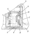
- the drawing shows a section through an arrangement according to the invention Fuel pump 1 in a swirl pot 2 of a fuel tank 3 of a vehicle internal combustion engine.
- the swirl pot 2 has an upwardly open storage chamber 4, in the central the fuel pump 1 is arranged and via a first pump stage 5 from the Fuel tank 3 sucks fuel through a filter 6 and into the storage chamber 4 promotes. The fuel delivered in excess fills the storage chamber 4 to Overflow 7. A second pump stage 8 sucks fuel out of the storage chamber 4 and promotes this, adapted to the needs of the internal combustion engine, via a line 9 to Internal combustion engine.
- the first pump stage 5 by a Electric motor chamber 10 of the fuel pump 1 in the storage chamber 4 of the Rolling pot 2 promotes so that the electric motor / fuel pump through in excess amount of fuel delivered is cooled.
Landscapes
- Engineering & Computer Science (AREA)
- Chemical & Material Sciences (AREA)
- Combustion & Propulsion (AREA)
- Mechanical Engineering (AREA)
- General Engineering & Computer Science (AREA)
- Cooling, Air Intake And Gas Exhaust, And Fuel Tank Arrangements In Propulsion Units (AREA)
- Details Of Reciprocating Pumps (AREA)
- Output Control And Ontrol Of Special Type Engine (AREA)
Description
Claims (1)
- Anordnung einer Brennstoffpumpe in einen Schlingertopf (2) eines Brennstofftanks einer Fahrzeug-Brennkraftmaschine, bei der eine erste Pumpenstufe (5) gegenüber einer zweiten im Überschuß in den Schlingertopf (2) hinein und die zweite heraus fördern, dadurch gekennzeichnet, daß die erste Pumpenstufe (5) durch eine Elektromotorkammer (10), der Brennstoffpumpe in den Schlingertopf (2) fördert.
Applications Claiming Priority (2)
| Application Number | Priority Date | Filing Date | Title |
|---|---|---|---|
| DE19627581A DE19627581A1 (de) | 1996-07-09 | 1996-07-09 | Anordnung einer Brennstoffpumpe |
| DE19627581 | 1996-07-09 |
Publications (3)
| Publication Number | Publication Date |
|---|---|
| EP0822331A2 EP0822331A2 (de) | 1998-02-04 |
| EP0822331A3 EP0822331A3 (de) | 1998-03-18 |
| EP0822331B1 true EP0822331B1 (de) | 2001-01-03 |
Family
ID=7799307
Family Applications (1)
| Application Number | Title | Priority Date | Filing Date |
|---|---|---|---|
| EP97105985A Expired - Lifetime EP0822331B1 (de) | 1996-07-09 | 1997-04-11 | Anordung einer Brennstoffpumpe |
Country Status (3)
| Country | Link |
|---|---|
| EP (1) | EP0822331B1 (de) |
| DE (2) | DE19627581A1 (de) |
| ES (1) | ES2154000T3 (de) |
Families Citing this family (2)
| Publication number | Priority date | Publication date | Assignee | Title |
|---|---|---|---|---|
| DE10062452A1 (de) * | 2000-12-14 | 2002-06-20 | Siemens Ag | Kraftstoffpumpe für ein Kraftfahrzeug |
| DE102004010357A1 (de) * | 2004-03-03 | 2005-09-22 | Siemens Ag | Fördereinheit |
Family Cites Families (2)
| Publication number | Priority date | Publication date | Assignee | Title |
|---|---|---|---|---|
| DE3713276C2 (de) * | 1987-04-18 | 1996-03-21 | Pierburg Gmbh | Brennstoffördereinrichtung für eine Brennkraftmaschine |
| FR2695964B1 (fr) * | 1992-09-24 | 1995-07-21 | Walbro Corp | Circuit de distribution de carburant pour moteur a combustion interne. |
-
1996
- 1996-07-09 DE DE19627581A patent/DE19627581A1/de not_active Withdrawn
-
1997
- 1997-04-11 DE DE59702840T patent/DE59702840D1/de not_active Expired - Fee Related
- 1997-04-11 ES ES97105985T patent/ES2154000T3/es not_active Expired - Lifetime
- 1997-04-11 EP EP97105985A patent/EP0822331B1/de not_active Expired - Lifetime
Also Published As
| Publication number | Publication date |
|---|---|
| DE19627581A1 (de) | 1998-01-15 |
| DE59702840D1 (de) | 2001-02-08 |
| EP0822331A2 (de) | 1998-02-04 |
| EP0822331A3 (de) | 1998-03-18 |
| ES2154000T3 (es) | 2001-03-16 |
Similar Documents
| Publication | Publication Date | Title |
|---|---|---|
| EP1012470B1 (de) | Kraftstoffversorgungssystem | |
| DE4231731C2 (de) | Auf Druck ansprechendes Kraftstoffzuführsystem | |
| DE19525542A1 (de) | Heizeinrichtung | |
| DE3034730A1 (de) | Verfahren zur aufloesung bzw. zur verhinderung von bei tiefer temperatur entstehenden ausscheidungen in einer fluessigkeit, insbesondere in einem treibstoff, und anordnung zur durchfuehrung des verfahrens | |
| DE3726332C1 (de) | Ansaugleitungsteil einer Brennkraftmaschine | |
| DE2736153A1 (de) | Filter- und mischeinrichtung zur vermischung von schmieroel und kraftstoff | |
| DE69909693T2 (de) | Brennstoffzufuhrvorrichtung für Dieselmotor und Filter dafür | |
| EP0822331B1 (de) | Anordung einer Brennstoffpumpe | |
| DE2952375C2 (de) | Ansaug-Drosselventilanordnung für eine Brennkraftmaschine | |
| DE19510494A1 (de) | Brennstoffversorgungssystem für Brennkraftmaschinen | |
| DE19631981B4 (de) | Vorrichtung zum Kühlen eines Kraftstoffes eines geschlossenen Kraftstoffversorgungskreislaufes eines Dieselaggregats | |
| DE19609799C2 (de) | Druckspeichereinspritzsystem | |
| DE3709591C2 (de) | ||
| DE2810980A1 (de) | Oelgekuehlter verbrennungsmotor | |
| DE3716429A1 (de) | Kraftstoffeinspritzduese | |
| DE19736133A1 (de) | Kühlmittelkreislauf für einen Verbrennungsmotor eines Kraftfahrzeuges | |
| DE4100973C1 (en) | Fuel pump for IC engine - has electromotor driving two units, first delivering greater vol. and formed as side channel pump | |
| DE10322197B4 (de) | Vorrichtung zur Kraftstoffzuführung | |
| DE3231903A1 (de) | Heizeinrichtung | |
| DE29509774U1 (de) | Brennstoffversorgungssystem für Brennkraftmaschinen | |
| EP0822330B1 (de) | Brennstoffversorgungssystem für Brennkraftmaschinen | |
| DE396593C (de) | Spritzvergaser mit verdeckt liegender Brennstoffduese | |
| DE3421815A1 (de) | Elektrische heizeinrichtung fuer dieselkraftstoff | |
| EP0780568A1 (de) | Kraftstoff-Fördersystem | |
| DE6604583U (de) | Heizvorrichtung fuer fluechtige brennstoffe, insbesondere zur verwendung in motorfahrzeugen |
Legal Events
| Date | Code | Title | Description |
|---|---|---|---|
| PUAI | Public reference made under article 153(3) epc to a published international application that has entered the european phase |
Free format text: ORIGINAL CODE: 0009012 |
|
| PUAL | Search report despatched |
Free format text: ORIGINAL CODE: 0009013 |
|
| 17P | Request for examination filed |
Effective date: 19970411 |
|
| AK | Designated contracting states |
Kind code of ref document: A2 Designated state(s): DE ES FR GB IT |
|
| AK | Designated contracting states |
Kind code of ref document: A3 Designated state(s): DE ES FR GB IT |
|
| AKX | Designation fees paid |
Free format text: DE ES FR GB IT |
|
| RBV | Designated contracting states (corrected) |
Designated state(s): DE ES FR GB IT |
|
| GRAG | Despatch of communication of intention to grant |
Free format text: ORIGINAL CODE: EPIDOS AGRA |
|
| 17Q | First examination report despatched |
Effective date: 20000427 |
|
| GRAG | Despatch of communication of intention to grant |
Free format text: ORIGINAL CODE: EPIDOS AGRA |
|
| GRAH | Despatch of communication of intention to grant a patent |
Free format text: ORIGINAL CODE: EPIDOS IGRA |
|
| GRAH | Despatch of communication of intention to grant a patent |
Free format text: ORIGINAL CODE: EPIDOS IGRA |
|
| ITF | It: translation for a ep patent filed | ||
| GRAA | (expected) grant |
Free format text: ORIGINAL CODE: 0009210 |
|
| AK | Designated contracting states |
Kind code of ref document: B1 Designated state(s): DE ES FR GB IT |
|
| ET | Fr: translation filed | ||
| REF | Corresponds to: |
Ref document number: 59702840 Country of ref document: DE Date of ref document: 20010208 |
|
| REG | Reference to a national code |
Ref country code: ES Ref legal event code: FG2A Ref document number: 2154000 Country of ref document: ES Kind code of ref document: T3 |
|
| GBT | Gb: translation of ep patent filed (gb section 77(6)(a)/1977) |
Effective date: 20010222 |
|
| PLBE | No opposition filed within time limit |
Free format text: ORIGINAL CODE: 0009261 |
|
| STAA | Information on the status of an ep patent application or granted ep patent |
Free format text: STATUS: NO OPPOSITION FILED WITHIN TIME LIMIT |
|
| REG | Reference to a national code |
Ref country code: GB Ref legal event code: IF02 |
|
| 26N | No opposition filed | ||
| PGFP | Annual fee paid to national office [announced via postgrant information from national office to epo] |
Ref country code: GB Payment date: 20030326 Year of fee payment: 7 |
|
| PGFP | Annual fee paid to national office [announced via postgrant information from national office to epo] |
Ref country code: DE Payment date: 20030331 Year of fee payment: 7 |
|
| PGFP | Annual fee paid to national office [announced via postgrant information from national office to epo] |
Ref country code: FR Payment date: 20030408 Year of fee payment: 7 |
|
| PGFP | Annual fee paid to national office [announced via postgrant information from national office to epo] |
Ref country code: ES Payment date: 20030422 Year of fee payment: 7 |
|
| REG | Reference to a national code |
Ref country code: FR Ref legal event code: CJ |
|
| PG25 | Lapsed in a contracting state [announced via postgrant information from national office to epo] |
Ref country code: GB Free format text: LAPSE BECAUSE OF NON-PAYMENT OF DUE FEES Effective date: 20040411 |
|
| PG25 | Lapsed in a contracting state [announced via postgrant information from national office to epo] |
Ref country code: ES Free format text: LAPSE BECAUSE OF NON-PAYMENT OF DUE FEES Effective date: 20040412 |
|
| PG25 | Lapsed in a contracting state [announced via postgrant information from national office to epo] |
Ref country code: DE Free format text: LAPSE BECAUSE OF NON-PAYMENT OF DUE FEES Effective date: 20041103 |
|
| GBPC | Gb: european patent ceased through non-payment of renewal fee |
Effective date: 20040411 |
|
| PG25 | Lapsed in a contracting state [announced via postgrant information from national office to epo] |
Ref country code: FR Free format text: LAPSE BECAUSE OF NON-PAYMENT OF DUE FEES Effective date: 20041231 |
|
| REG | Reference to a national code |
Ref country code: FR Ref legal event code: ST |
|
| PG25 | Lapsed in a contracting state [announced via postgrant information from national office to epo] |
Ref country code: IT Free format text: LAPSE BECAUSE OF NON-PAYMENT OF DUE FEES Effective date: 20050411 |
|
| REG | Reference to a national code |
Ref country code: ES Ref legal event code: FD2A Effective date: 20040412 |