EP0822105A2 - Notlaufreifen und Verfahren zu dessen Herstellung - Google Patents
Notlaufreifen und Verfahren zu dessen Herstellung Download PDFInfo
- Publication number
- EP0822105A2 EP0822105A2 EP97113216A EP97113216A EP0822105A2 EP 0822105 A2 EP0822105 A2 EP 0822105A2 EP 97113216 A EP97113216 A EP 97113216A EP 97113216 A EP97113216 A EP 97113216A EP 0822105 A2 EP0822105 A2 EP 0822105A2
- Authority
- EP
- European Patent Office
- Prior art keywords
- tire
- bead
- sidewall
- crescent
- tread
- Prior art date
- Legal status (The legal status is an assumption and is not a legal conclusion. Google has not performed a legal analysis and makes no representation as to the accuracy of the status listed.)
- Granted
Links
Images


Classifications
-
- B—PERFORMING OPERATIONS; TRANSPORTING
- B60—VEHICLES IN GENERAL
- B60C—VEHICLE TYRES; TYRE INFLATION; TYRE CHANGING; CONNECTING VALVES TO INFLATABLE ELASTIC BODIES IN GENERAL; DEVICES OR ARRANGEMENTS RELATED TO TYRES
- B60C15/00—Tyre beads, e.g. ply turn-up or overlap
- B60C15/0009—Tyre beads, e.g. ply turn-up or overlap features of the carcass terminal portion
- B60C15/0072—Tyre beads, e.g. ply turn-up or overlap features of the carcass terminal portion with ply reverse folding, i.e. carcass layer folded around the bead core from the outside to the inside
-
- B—PERFORMING OPERATIONS; TRANSPORTING
- B29—WORKING OF PLASTICS; WORKING OF SUBSTANCES IN A PLASTIC STATE IN GENERAL
- B29D—PRODUCING PARTICULAR ARTICLES FROM PLASTICS OR FROM SUBSTANCES IN A PLASTIC STATE
- B29D30/00—Producing pneumatic or solid tyres or parts thereof
- B29D30/06—Pneumatic tyres or parts thereof (e.g. produced by casting, moulding, compression moulding, injection moulding, centrifugal casting)
- B29D30/08—Building tyres
- B29D30/20—Building tyres by the flat-tyre method, i.e. building on cylindrical drums
-
- B—PERFORMING OPERATIONS; TRANSPORTING
- B29—WORKING OF PLASTICS; WORKING OF SUBSTANCES IN A PLASTIC STATE IN GENERAL
- B29D—PRODUCING PARTICULAR ARTICLES FROM PLASTICS OR FROM SUBSTANCES IN A PLASTIC STATE
- B29D30/00—Producing pneumatic or solid tyres or parts thereof
- B29D30/06—Pneumatic tyres or parts thereof (e.g. produced by casting, moulding, compression moulding, injection moulding, centrifugal casting)
- B29D30/72—Side-walls
-
- B—PERFORMING OPERATIONS; TRANSPORTING
- B60—VEHICLES IN GENERAL
- B60C—VEHICLE TYRES; TYRE INFLATION; TYRE CHANGING; CONNECTING VALVES TO INFLATABLE ELASTIC BODIES IN GENERAL; DEVICES OR ARRANGEMENTS RELATED TO TYRES
- B60C13/00—Tyre sidewalls; Protecting, decorating, marking, or the like, thereof
-
- B—PERFORMING OPERATIONS; TRANSPORTING
- B60—VEHICLES IN GENERAL
- B60C—VEHICLE TYRES; TYRE INFLATION; TYRE CHANGING; CONNECTING VALVES TO INFLATABLE ELASTIC BODIES IN GENERAL; DEVICES OR ARRANGEMENTS RELATED TO TYRES
- B60C15/00—Tyre beads, e.g. ply turn-up or overlap
- B60C15/0009—Tyre beads, e.g. ply turn-up or overlap features of the carcass terminal portion
- B60C15/0018—Tyre beads, e.g. ply turn-up or overlap features of the carcass terminal portion not folded around the bead core, e.g. floating or down ply
-
- B—PERFORMING OPERATIONS; TRANSPORTING
- B60—VEHICLES IN GENERAL
- B60C—VEHICLE TYRES; TYRE INFLATION; TYRE CHANGING; CONNECTING VALVES TO INFLATABLE ELASTIC BODIES IN GENERAL; DEVICES OR ARRANGEMENTS RELATED TO TYRES
- B60C17/00—Tyres characterised by means enabling restricted operation in damaged or deflated condition; Accessories therefor
-
- B—PERFORMING OPERATIONS; TRANSPORTING
- B60—VEHICLES IN GENERAL
- B60C—VEHICLE TYRES; TYRE INFLATION; TYRE CHANGING; CONNECTING VALVES TO INFLATABLE ELASTIC BODIES IN GENERAL; DEVICES OR ARRANGEMENTS RELATED TO TYRES
- B60C9/00—Reinforcements or ply arrangement of pneumatic tyres
- B60C9/02—Carcasses
- B60C9/0207—Carcasses comprising an interrupted ply, i.e. where the carcass ply does not continuously extend from bead to bead but is interrupted, e.g. at the belt area, into two or more portions of the same ply
-
- B—PERFORMING OPERATIONS; TRANSPORTING
- B60—VEHICLES IN GENERAL
- B60C—VEHICLE TYRES; TYRE INFLATION; TYRE CHANGING; CONNECTING VALVES TO INFLATABLE ELASTIC BODIES IN GENERAL; DEVICES OR ARRANGEMENTS RELATED TO TYRES
- B60C9/00—Reinforcements or ply arrangement of pneumatic tyres
- B60C9/02—Carcasses
- B60C9/14—Carcasses built-up with sheets, webs, or films of homogeneous material, e.g. synthetics, sheet metal, rubber
-
- B—PERFORMING OPERATIONS; TRANSPORTING
- B29—WORKING OF PLASTICS; WORKING OF SUBSTANCES IN A PLASTIC STATE IN GENERAL
- B29D—PRODUCING PARTICULAR ARTICLES FROM PLASTICS OR FROM SUBSTANCES IN A PLASTIC STATE
- B29D30/00—Producing pneumatic or solid tyres or parts thereof
- B29D30/06—Pneumatic tyres or parts thereof (e.g. produced by casting, moulding, compression moulding, injection moulding, centrifugal casting)
- B29D30/08—Building tyres
- B29D30/20—Building tyres by the flat-tyre method, i.e. building on cylindrical drums
- B29D2030/201—Manufacturing run-flat tyres
-
- B—PERFORMING OPERATIONS; TRANSPORTING
- B29—WORKING OF PLASTICS; WORKING OF SUBSTANCES IN A PLASTIC STATE IN GENERAL
- B29D—PRODUCING PARTICULAR ARTICLES FROM PLASTICS OR FROM SUBSTANCES IN A PLASTIC STATE
- B29D30/00—Producing pneumatic or solid tyres or parts thereof
- B29D30/06—Pneumatic tyres or parts thereof (e.g. produced by casting, moulding, compression moulding, injection moulding, centrifugal casting)
- B29D30/72—Side-walls
- B29D2030/724—Stiffening the sidewalls, e.g. by using additional inserts, e.g. made of rubber, plastics or other materials
-
- B—PERFORMING OPERATIONS; TRANSPORTING
- B29—WORKING OF PLASTICS; WORKING OF SUBSTANCES IN A PLASTIC STATE IN GENERAL
- B29L—INDEXING SCHEME ASSOCIATED WITH SUBCLASS B29C, RELATING TO PARTICULAR ARTICLES
- B29L2030/00—Pneumatic or solid tyres or parts thereof
- B29L2030/007—Sidewalls
-
- Y—GENERAL TAGGING OF NEW TECHNOLOGICAL DEVELOPMENTS; GENERAL TAGGING OF CROSS-SECTIONAL TECHNOLOGIES SPANNING OVER SEVERAL SECTIONS OF THE IPC; TECHNICAL SUBJECTS COVERED BY FORMER USPC CROSS-REFERENCE ART COLLECTIONS [XRACs] AND DIGESTS
- Y02—TECHNOLOGIES OR APPLICATIONS FOR MITIGATION OR ADAPTATION AGAINST CLIMATE CHANGE
- Y02T—CLIMATE CHANGE MITIGATION TECHNOLOGIES RELATED TO TRANSPORTATION
- Y02T10/00—Road transport of goods or passengers
- Y02T10/80—Technologies aiming to reduce greenhouse gasses emissions common to all road transportation technologies
- Y02T10/86—Optimisation of rolling resistance, e.g. weight reduction
-
- Y—GENERAL TAGGING OF NEW TECHNOLOGICAL DEVELOPMENTS; GENERAL TAGGING OF CROSS-SECTIONAL TECHNOLOGIES SPANNING OVER SEVERAL SECTIONS OF THE IPC; TECHNICAL SUBJECTS COVERED BY FORMER USPC CROSS-REFERENCE ART COLLECTIONS [XRACs] AND DIGESTS
- Y10—TECHNICAL SUBJECTS COVERED BY FORMER USPC
- Y10T—TECHNICAL SUBJECTS COVERED BY FORMER US CLASSIFICATION
- Y10T152/00—Resilient tires and wheels
- Y10T152/10—Tires, resilient
- Y10T152/10495—Pneumatic tire or inner tube
- Y10T152/10819—Characterized by the structure of the bead portion of the tire
- Y10T152/10828—Chafer or sealing strips
-
- Y—GENERAL TAGGING OF NEW TECHNOLOGICAL DEVELOPMENTS; GENERAL TAGGING OF CROSS-SECTIONAL TECHNOLOGIES SPANNING OVER SEVERAL SECTIONS OF THE IPC; TECHNICAL SUBJECTS COVERED BY FORMER USPC CROSS-REFERENCE ART COLLECTIONS [XRACs] AND DIGESTS
- Y10—TECHNICAL SUBJECTS COVERED BY FORMER USPC
- Y10T—TECHNICAL SUBJECTS COVERED BY FORMER US CLASSIFICATION
- Y10T152/00—Resilient tires and wheels
- Y10T152/10—Tires, resilient
- Y10T152/10495—Pneumatic tire or inner tube
- Y10T152/10855—Characterized by the carcass, carcass material, or physical arrangement of the carcass materials
- Y10T152/10864—Sidewall stiffening or reinforcing means other than main carcass plies or foldups thereof about beads
Definitions
- Run-flat tires have certain advantages over standard tires not designed to allow the vehicle to continue running with a loss of inflation pressure. Some of these advantages are follows :
- run-flat tires Numerous variations of run-flat tires have been developed. These involve changes to the structure of the tire itself and modifications to the rim to hold and support the flat tire. Each variation is limited by safety restrictions on vehicle speed, length of travel, zero inflation pressure handling and the magnitude of the lateral accelerations that force the bead of the tire off the rim seat. Further, the best solutions are those which do not affect the vehicle's nominal performance. The inflated ride comfort and handling should not be compromised by the design of the run-flat tire. Therefore, the need for improvements in the design of run-flat tires continues.
- a number of patents disclose a thickened sidewall design feature including a plurality of reinforcing members and a plurality of carcass layers. These include U.S. Patent Nos. 5,238,040 ; 5,368,082 ; 5,427,166 ; and 5,511,599, and European Patent (EP) No. 385,192.
- U.S. 5,238,040 three reinforcement inserts are interposed between first and second carcass plies.
- a third textile reinforcing strip to the inside of the thickened sidewall portion extends from the crown area of the tire to a mid-height of the sidewall.
- the third strip reduces possible rubbing friction to increase the time for the tire to fail due to temperature and crushing conditions.
- U.S. 5,368,082 describes a run-flat tire with elastomeric first and second fillers and a carcass reinforcing structure with two plies from bead to bead having turnup ends wrapped around each bead.
- the second filler is between the first and second carcass plies.
- the turnup ends terminate in radial proximity of the maximum section width of the tire.
- a special flat base bead core keeps the tire seated on a rim after the difficulty in mounting the tire on the rim has been overcome.
- U.S. 5,427,166 and 5,511,599 both include three carcass layers extending from bead to bead.
- a middle carcass layer has turned up portions around each bead core and is interposed between first and second crescent-shaped reinforcing members in each sidewall.
- a third reinforcing member is disclosed in U.S. 5,511,599 to extend radially outward from and contiguous with a bead filler.
- a lenticular (crescent-shaped) section member disposed at the inside of the sidewall has a textile reinforcement insert.
- the insert divides the lenticular section member and extends radially outward from a side center line to as far as under the end of the belt.
- the insert extends from one end radially outward of a bead filler in one sidewall to the other end in a similar location in the other sidewall.
- the manufacturing of run-flat tires having reinforced sidewalls involves the assembly of a large number of components when compared to a tire with no sidewall reinforcing members.
- the addition of crescent-shaped reinforcing members disposed with a plurality of carcass layers becomes very difficult and time consuming during the tire building process, especially when laying components on a tire building drum.
- carcass layers generally extend from bead to bead and may encircle the bead to wrap around the bead core and extend radially outward into the sidewall. These carcass layers result in further time delays and complexity in the building run-flat tires. A need exists to simplify the run-flat tire and the tire manufacturing process to maintain productivity at generally acceptable levels.
- Tires with reinforced sidewalls as previously discussed may be simplified by truncating carcass layers in either or both the bead area and the crown area of the tire to provide partial.
- Typical patents which illustrate partial carcass layers include U.S. Patent Nos. 4,067,372 ; 4,287,924 ; 5,164,029 ; 5,217,549 ; and 5,361,820, European Patent No. 385,192 and Japanese (JP) Patent No. 3-143710.
- U.S. Patent No. 4,067,374 discloses the use of a crescent-shaped sidewall reinforcing rubber portion positioned to the inside of partial carcass layers.
- the crescent-shape sidewall reinforcing member is put into compression while the cords of the partial carcass layers are put into tension with the loss of inflation pressure in the tire ; thereby inhibiting collapse of the sidewall.
- the partial carcass layers each extend from a respective bead core to overlap the lateral edges of the belt. Partial carcass layers are formed by incorporating reinforcing fibers in a rubbery mixture.
- the other carcass layer is located to the inside of the reinforcing member and extends from bead to bead and is wrapped around each bead. This carcass layer would also be in tension with the loss of inflation pressure.
- a two part crescent-shaped member has a heat conducting sheet or layer between the two parts.
- the layer extends over the whole height of the crescent-shaped portions and the two crescent-shaped parts are of different flexibility.
- the heat conducting layer may have parallel metallic cords extending radially to assist in the heat conductivity.
- the height of the disclosed tire of this patent is only 31 percent of its inflated height when the inflation pressure is zero.
- carcass reinforcing layers are disposed on either one or both sides of a carcass.
- Reinforcing layers are partial layers extending from a lapping arrangement with the belt edge to a location outward of the bead core.
- a two component bead apex is further disclosed having a stiffener portion made of hard rubber and a buffer portion. The reinforcing layers and the bead apex help support the tire by increasing lateral and vertical spring coefficients of the tire.
- the tire of this patent improves the tire's vibration performance and provides only limited self supporting capability.
- the pair of crescent-shaped elastomeric reinforcing members disclosed in U.S. 5,217,549 are preferably for high profile tires having a section height of 5 inches (127 millimeters) or greater.
- Sidewall stiffness is achieved by a single high modulus crescent-shaped reinforcing member in each sidewall to the inside of two carcass plies and a reinforced bias ply adjacent to the two carcass plies.
- the bias ply extends radially inward from each lateral edge of the belt to a location radially outward of the bead core and are bias at an angle of 60 degrees.
- the radial tire disclosed in U.S. 5,361,820 includes a carcass layer composed of a single ply of carcass cords folded up around the bead core to an radial outward position below the belts.
- a hard rubber layer is disposed between the carcass layer and the folded-up portion to insure a high lateral spring constant to maintain good maneuverability.
- the tire of this patent has an improved production rate and a reduced tire weight when compared to other tires with a high lateral spring constant.
- a textile reinforcement insert is positioned in the crown area of the tire and extends radially inward to divide a crescent-shaped reinforcing member.
- the insert stops at a distance radially outward of the bead core beyond the apex of the bead filler.
- the insert lies along the center axis of the crescent-shaped member.
- the crescent-shaped member also terminates at the radial outermost extent of the bead filler in this patent.
- a cord reinforcing unit on the interior surface of the crescent-shaped reinforcing member in JP 3-143710 consists of at least one reinforced ply.
- the reinforcing member is to the inside of two carcass plies which wrap around the bead core.
- the inner reinforcing unit extends outward from a location above the bead core to a lapping arrangement with the belt layer.
- the reinforcing member and the reinforcing unit provides the overall sidewall support for run-flat performance. Only one crescent- shaped reinforcing member is illustrated.
- a typical method for manufacturing tires is illustrated and disclosed in U.S. 5,215,612. Portions of a green tire are assembled or formed by wrapping uncured tire components around a forming or tire building drum. A plurality of pieces or components are placed at both lateral sides of a continuous carcass ply which is subsequently wrapped around a bead core.
- U.S. 5,215,612 the importance of bonding rubber pieces on the end of a sidewall rubber portions in building the tire is disclosed. This method becomes essential in reducing the tire's production time when a large number of sidewall components are present in the formation of the green tire on a building drum.
- references fail to teach how to improve the production time of a run-flat tire having a plurality of crescent-shaped reinforcing members and carcass layers.
- a desirable production capacity would be the ability to produce a run-flat tire having sidewall supporting capabilities in approximately the same time as a standard tire having no sidewall supporting capability.
- Tire manufacturing plants must be able to produce enough tires to meet the constant demand for tires that exists.
- An object of this invention is to provide a run-flat tire which demonstrates improved vehicle performance under deflated conditions and yet achieves the same vehicle performance as a standard tire when inflated.
- the tire of this invention may further include the inner sidewall supporting complexes each having two reinforced partial carcass layers, being first and second partial carcass layers, extending from a respective bead core to a lapping arrangement with a respective lateral end of the tread reinforcing package.
- the inner sidewall supporting complexes may include a filler rubber portion disposed between the two partial carcass layers to extend from the respective bead core to a lapping arrangement with the respective lateral end of the tread reinforcing package.
- Each load bearing sidewall comprises a first crescent-shaped reinforcing member disposed to the outside of the innerliner portion.
- An inner carcass layer is disposed to the outside of the first reinforcing member to extend from sidewall to sidewall and radially inward so that each edge of the inner carcass layer wraps around a respective bead core to form a turned up carcass portion.
- An inner sidewall supporting complex is disposed to the exterior of the inner carcass layer.
- the supporting complex includes first and second partial carcass layers extending from a respective bead core to a lapping arrangement with the tread reinforcing package, a second crescent-shaped reinforcing member located to the inside of the partial carcass layers and a filler rubber portion positioned between the first and second partial carcass layers.
- the reference planes include at least a pair of bead reference planes each associated with a respective bead core and a pair of shoulder reference planes each associated with a respective lateral edge of the tread reinforcing package.
- the reference planes are to be used for assembling the components of the green tire on the drum.
- a second step includes placing the innerliner ply around the building drum to extend generally from one bead reference plane to the other bead reference plane.
- a third step includes providing a pair of first crescent-shaped reinforcing members each placed around the drum to be radially outside the innerliner ply and located in a lapping arrangement with a respective shoulder reference plane.
- the method includes providing an inner carcass layer with generally parallel reinforcing members to provide a radial tire carcass and placing the inner carcass layer around the drum to extend axially outside of the one bead reference plane to a location axially outside the other bead reference plane.
- a sixth step includes providing a pair of pre-assembled inner sidewall supporting complexes of the self-supporting sidewalls each formed as a unit and including a second crescent-shaped reinforcing member, a first partial carcass layer affixed to one side of the second reinforcing member, a filler rubber portion having one side affixed to an outer side of the first partial carcass layer and a second partial carcass layer affixed to an outer side of the filler rubber portion.
- a seventh step includes placing each one of the supporting complexes around the drum to the outside of the inner carcass layer such that the second crescent-shaped reinforcing member contacts the inner carcass layer and the first and second partial carcass layers each extend in a lapping arrangement with a respective shoulder reference plane and the filler rubber portion is also in a lapping arrangement with the respective shoulder reference plane as well as the bead reference plane.
- the method includes placing a respective bead core around the drum at each bead reference plane to be radially outside of and in contact with a respective filler rubber portion.
- a ninth step includes folding both a filler end portion of each filler rubber portion and a turned up carcass portion at each edge of the inner carcass layer around a respective bead core to encircle the respective bead core.
- a tenth step includes providing a pair of pre-assembled sidewall and bead protecting complexes each formed as a unit and including a sidewall rubber, a bead support rubber affixed to an end of the sidewall rubber and a rim protector ply affixed to the bead support rubber.
- the features of the run-flat tire of this invention include the load bearing sidewall portions each having crescent-shaped reinforcing members interposed with carcass layers.
- One of the essential three reinforced carcass layers extend the full width and depth of the tire from bead to bead and wrap around the bead core to extend radially outward into the tire's sidewall.
- the other two carcass layers each have two portions where each portion extends from a bead core radially outward to a lapping arrangement with a tread reinforcing package. These portions provide two partial carcass layers on each side of the tire within the sidewall having reinforcing cords.
- the bias of carcass reinforcing cords from a radial plane is determined by the vehicle application.
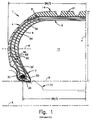
- the inner carcass layer 6A divides the first crescent-shaped member 5A from the second crescent-shaped member 5B.
- the sidewall 4 is outside the middle and outer carcass layers 6B,6C and an innerliner ply 9 is interior to the first crescent-shaped reinforcing member 5A.
- the crescent-shaped members extend radially outward and axially inward to lap over the lateral edge of the belt package 8.
- the bead reference D establishes a reference for defining the section height H of the tire.
- the rim width BW is defined from center to center of the bead cores 3B.
- run-flat tires of this invention have partial carcass layers as illustrated in the embodiments of Figs 4 and 6. These partial carcass layers provide the necessary means for run-flat tires to be manufactured with increased efficiency, without a compromise in performance.
- the following sections further define the structure and procedures necessary to achieve the objects of this invention.
- Manufacturing efficiency in building the run-flat tire is greatly enhanced by considering the self supporting sidewalls to have five components plus the bead core, as illustrated in Fig. 2.
- the five components are arranged as they exist in the run-flat tire radially outward from the innerliner ply 44 (component 1) to the sidewall protecting complex 40 (component 5).
- Each one of these five components is considered as a single unit in forming the green run-flat tire during the tire building process.
- Relative locations of the components in a cross-section can refer to either or both a bead reference plane B and a shoulder reference plane S ; both planes being perpendicular to the cross-section.
- the bead reference plane is defined as a plane through the center of a respective bead core 22 normal to the interior surface of the cured run-flat tire, as illustrated in Figs. 4 and 6.
- the shoulder reference plane is defined as a plane from a respective end 83 of the inner belt 82 of the tread reinforcing package 80 normal to the interior surface of the cured run-flat tire, also illustrated in Figs. 4 and 6.
- a cured run-flat tire can be realized with relatively small changes in production efficiency.
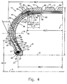
- the cured tire which results is illustrated in Fig. 4.
- the overall section height H is measured from the bead reference D.
- the overall section width SW is measured in the maximum width median plane M.
- the ratio of the section height H to the overall section width SW is the aspect ratio of the tire. Aspect ratios between 0.40 to 0.65 are preferred values for the cured run-flat tire of this invention.
- the bead reference plane B-B and the shoulder reference plane S-S are again inclined with respect to one another in a cured tire 10.
- the location of the various products can be again referenced to these planes in the cured run-flat tire.
- the bead reference D is established by a line parallel to the axis of rotation A from the intersection of a radial line 23 from the center of the bead core 22 and the innermost surface of the bead protector ply 27 at point 25.
- the sidewall and bead protecting complexes 40 of this preferred embodiment run-flat tire 10 each extend from a position radially inside the bead core to a lateral edge of the tread 12.
- the protecting complexes each include a sidewall rubber 42, a bead support rubber 34 and a reinforced bead protector ply 27.
- the bead support rubber and the bead protector ply have been wrapped around the bead core to interface with the innerliner ply 44 to the inside of the run-flat tire at an end 31 of the protector ply.
- the overall profile of the self supporting sidewalls are shaped in a manner to provide the best equilibrium curve for generating normal and lateral forces on the tire during inflated running.
- a thickness T of the load bearing sidewall portion including a sidewall rubber 42, the inner, first partial and second partial carcass layers 68,62,64, the first and second crescent-shaped reinforcing members 54 and 56, the filler rubber portion 24 and the innerliner portion 44, is approximately constant over its radial extent.
- First and second crescent-shaped members 54 and 56 are axially inward of the first partial carcass layer 62 and the first crescent-shaped member is in contact with the outside face of the innerliner portion 44.
- the first and second crescent-shaped reinforcing members extend to a crown points 58 and 52 respectively in the crown area of the tire to provide the lapping arrangement with the inner belt edge 83 of tread reinforcing package 80.
- the first reinforcing member has a lap distance L4 and the second reinforcing member has a lap distance L3 approximately equal to L4. Both lap distances L3 and L4 are at least 20 millimeters.
- the axial distance E2 is at least 10 millimeters.
- the axial distance E2-E3 between the end 65 of the first partial carcass layer and the end 69 of the second partial carcass layer is at least 5 millimeters.
- the reinforcing members 54 and 56 extend radially inward to end points 59 and 53 radially outward of the bead core 22. The properties of these crescent-shaped members are discussed later.
- the belt package 80 is located radially outward of the carcass layers 62, 64 and 68 in the crown portion 14 of the run-flat tire 10.
- the belt package has a wide inner belt 82 and at least one narrower outer belt 84 (Fig. 4).
- a cap ply 86 has a width to axially extend beyond both lateral edges 83 of the innermost belt 82 to a outer lateral edge 81.
- the cap ply may have its lateral edges modified to increase its durability.
- end positions 52 and 53 of the second crescent-shaped reinforcing members as illustrated in Fig. 4, the performance of the run-flat tire can be further adjusted for vehicle suspension variations.
- the preferred tire end positions 58 and 59 of the first crescent-shaped member adjacent are as shown in Fig. 4.
- the radially outward end position 58 is located axially inward of the lateral end 83 of the belt package 80 a distance of at least 20 millimeters.
- the rubber filler portion 24 starts at the bead core 22 and extends radially outward to an end location adjacent the lateral end of the belt package 80.
- FIG. 5a Exemplary changes are illustrated in Figs. 5a through 5e to the preferred supporting complex 50 illustrated as component IV of Fig. 2.
- the change illustrated in Fig. 5a is for the filler rubber portion 24a having been changed to have an apex 29a located approximately mid-distance between the bead reference plane B-B and the shoulder reference plane S-S.
- This supporting complex used in a run-flat tire will give the run-flat tire of Fig. 6, which is further discussed in more detail in a later section of this description.
- the filler rubber portion 24b has been truncated short of the bead reference plane B-B. This embodiment is necessary when tire building means are not available for turning up the filler around a bead core.
- FIG. 5c Another embodiment of an inner sidewall supporting complex 50 is illustrated in Fig. 5c.
- the first partial carcass ply 62a has been extended such that its end 65a approaches the midcircumferential plane P-P.
- the end 65a is at an offset distance E5 from the mid circumferential plane P-P.
- the second partial carcass layer is extended to an end 67a for wrapping around the bead core to thereby provide a second turned up carcass portion.
- Either one or both of the changes illustrated in Fig. 5c can be realized as desired.
- the embodiment of the supporting complex illustrated in Fig. 5d includes both the first and second partial carcass layers having ends 65b and 69b respectively extended axially toward the midcircumferential plane P-P. This embodiment may be necessary to avoid terminating end 65b and/or end 69b under a circumferential groove in the tread 12 of the run-flat tire.
- a fifth change in the supporting complexes 50 is illustrated in Fig. 5e to provide another embodiment of the invention.
- a larger second crescent shaped reinforcing member 56a is provided to better support the sidewalls of the tire.
- Both ends 52a and 53a are extended axially beyond their previous axial extent in making this change.
- the ends 65c and 69c of the partial carcass layers have also been extended to maintain carcass end distances E2 and E3 as illustrated.
- the distance between an end 65-65c of the first partial carcass layer and a respective end 69-69c of the second partial carcass layer, defined by the distance E2-E3, is at least 5 millimeters in each supporting complex.
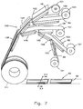
- a system and apparatus for automatically or semi-automatically assembling the inner sidewall supporting complex 50 is illustrated in a generic manner in Fig. 7.
- a system of five spools 101 is provided in which each spool contains one component of the inner sidewall supporting complex.
- a spool is provided for each of the components being assembled to include a belt edge protector 46, a second partial carcass layer 64, a filler rubber portion 24, a first partial carcass layer 62 and a second crescent-shaped reinforcing member 56.
- a continuous length of each component is rolled up on a spool to be unrolled during the assembly of the complex.
- An initial set of conveyors 102 support the products as they are discharged from the rollers 101.
- a second set of conveyors 104 support two components being placed together as a unit.
- the belt edge protector 46 is placed together with the second partial carcass layer 64 and the second partial carcass layer 62 is placed together with the second reinforcing member 56.
- a third conveyor 106 supports three products when combining the filler rubber portion 24 with the previously combined first partial carcass layer and the second reinforcing member.
- the final conveyor 108 supports the complete combination of all five components of the supporting complex 50.
- the inner sidewall supporting complex 50 is assembled for storage on a large spool 110, as illustrated in Fig. 7.
- the spool is transferred to the tire building drum for making the green tire (Fig. 3A).
- the supporting complex is unrolled from the large spool and cut to length for a particular tire type and size being made.
- a typical supporting complex when viewed as a cross-sectional cut along line 2.4 of Fig. 7, has a configuration as illustrated by component 4 of Fig. 2.
- Other shapes and sizes of the components of the supporting complex are within the scope of this invention, as illustrated in Fig. 5.
- the supporting complex is treated the same as any other single component when the green tire is being formed.
- the supporting complex 50 has a single planar cut 55 to provide a predetermined length, as illustrated in Fig. 7.
- This planar cut provides the tire builder with only a single joint to be formed when building the green tire on the tire building drum.
- the tire can be made more uniform with one joint instead of five joints ; being one for each component of the complex. This improves the quality of the run-flat tire produced.
- the outer sidewall protective complex 40 is assembled using the same type system and apparatus as described above for the supporting complex 50. Spools to include the sidewall rubber 42, the bead support rubber 34 and the bead protector ply 27 are used along with conveyors for assembling the protective complex 40. The protective complex is placed on a large spool for transporting to another location where the green tire is being formed. The protective complex is also cut to length along a single plane at each end for providing the tire builder with only a single joint to be formed when building the green tire on the tire building drum. This single joint instead of three joints for the three protective complex components also improves the uniformity of the run-flat tire.
- the run-flat tire of this invention can be constructed with only a limited number of components as well as manufacturing steps.
- the rubber in the tread rubber portion 12 and a sidewall rubber portion 42 may be of any suitable compound based on natural or synthetic rubber or any suitable combination thereof known in the art.
- the innerliner portion 44 is preferably of a halobutyl rubber.
- the first and second crescent-shaped members 54 and 56 have a Shore A hardness in the range of approximately 70 to 90 and a modulus of elasticity in compression at a ten percent unit strain in a range of approximately 7.0 to 15.0 MPa.
- the preferred Shore A hardness of the first and second crescent shaped members 54,56 is approximately 75 to 80 and their preferred modulus of elasticity is about 8.5 MPa.
- the first, second, and third crescent-shaped reinforcing members exhibit a relatively low hysteresis.
- the filler rubber portion 24 is a continuation of a bead filler located axially outward of the first partial carcass layer 62.
- the preferred embodiment of this invention is with the crescent-shaped reinforcing members 54 and 56, along with the filler rubber portion 24, having essentially the same material physical properties.
- Reinforcing members of the inner belt 82 are preferably of an metallic (i.e. steel) material.
- Reinforcing members in each of the outer belts 84 can be of an aromatic polyamide or preferably a metallic (i.e., steel) material.
- Belt reinforcing members are at an acute angle (16 to 30 seconds) with respect to the midcircumferential plane P of the tire.
- the cap ply 86 has reinforcing members preferably of a polyamide multi-filament (i.e., nylon) material which are approximately parallel to the midcircumferential plane.
- Other belt package and cap ply materials that maintain structural integrity of the tire may be used for the reinforcing members within the scope of this invention.
Landscapes
- Engineering & Computer Science (AREA)
- Mechanical Engineering (AREA)
- Tires In General (AREA)
- Tyre Moulding (AREA)
Applications Claiming Priority (2)
| Application Number | Priority Date | Filing Date | Title |
|---|---|---|---|
| US08/691,831 US5795416A (en) | 1996-08-02 | 1996-08-02 | Run-flat tire having partial carcass layers |
| US691831 | 2003-10-23 |
Publications (3)
| Publication Number | Publication Date |
|---|---|
| EP0822105A2 true EP0822105A2 (de) | 1998-02-04 |
| EP0822105A3 EP0822105A3 (de) | 1999-11-03 |
| EP0822105B1 EP0822105B1 (de) | 2004-04-14 |
Family
ID=24778160
Family Applications (1)
| Application Number | Title | Priority Date | Filing Date |
|---|---|---|---|
| EP97113216A Expired - Lifetime EP0822105B1 (de) | 1996-08-02 | 1997-07-31 | Notlaufreifen und Verfahren zu dessen Herstellung |
Country Status (7)
| Country | Link |
|---|---|
| US (2) | US5795416A (de) |
| EP (1) | EP0822105B1 (de) |
| JP (1) | JP3214666B2 (de) |
| BR (1) | BR9704241A (de) |
| CA (1) | CA2210979C (de) |
| DE (1) | DE69728614T2 (de) |
| MX (1) | MX9705907A (de) |
Cited By (20)
| Publication number | Priority date | Publication date | Assignee | Title |
|---|---|---|---|---|
| EP0938986A2 (de) * | 1998-02-27 | 1999-09-01 | Bridgestone Corporation | Luftreifen |
| EP0953462A2 (de) * | 1998-04-30 | 1999-11-03 | Bridgestone Corporation | Gummi/Stahlkord Verbundwerkstoff und PKW-Reifen |
| EP0985558A2 (de) * | 1998-09-08 | 2000-03-15 | Sumitomo Rubber Industries, Ltd. | Notlaufreifen |
| WO2000020235A1 (de) * | 1998-10-05 | 2000-04-13 | Dunlop Gmbh | Fahrzeugluftreifen |
| WO2000021763A1 (de) * | 1998-10-12 | 2000-04-20 | Dunlop Gmbh | Fahrzeugluftreifen |
| WO2000046047A1 (en) * | 1999-02-03 | 2000-08-10 | The Goodyear Tire & Rubber Company | Reinforced wedge-insert construction for extended mobility tires |
| WO2000046048A1 (en) * | 1999-02-05 | 2000-08-10 | The Goodyear Tire & Rubber Company | Discontinuous ply for runflat tire construction |
| US6142205A (en) * | 1998-03-13 | 2000-11-07 | The Goodyear Tire & Rubber Company | Tire with composite ply structure |
| EP1095797A1 (de) * | 1998-12-17 | 2001-05-02 | Bridgestone Corporation | Luftreifen |
| US6358346B1 (en) | 2000-07-28 | 2002-03-19 | The Goodyear Tire & Rubber Company | Method of building tire with composite ply structure |
| US6439283B1 (en) | 1997-05-29 | 2002-08-27 | The Goodyear Tire & Rubber Company | Runflat tire with tread stiffening member |
| US6494242B2 (en) | 1999-05-27 | 2002-12-17 | Michelin Recherche Et Technique | Runflat tire having optimized carcass path |
| WO2003022558A1 (fr) * | 2001-09-06 | 2003-03-20 | Bridgestone Corporation | Procede de fabrication d'un pneu |
| EP1361078A1 (de) * | 2002-05-11 | 2003-11-12 | Continental Aktiengesellschaft | Pannenlauffähiger Fahrzeugluftreifen |
| US6712108B1 (en) | 1999-02-05 | 2004-03-30 | The Goodyear Tire & Rubber Company | Discontinuous ply for runflat tire construction |
| US6763866B1 (en) | 1999-02-03 | 2004-07-20 | The Goodyear Tire & Rubber Company | Reinforced wedge-insert construction for extended mobility tires |
| EP1512524A1 (de) * | 2003-09-05 | 2005-03-09 | Continental Aktiengesellschaft | Verfahren zum Aufbau einer Reifenkarkasse |
| WO2005044546A1 (de) * | 2003-11-05 | 2005-05-19 | Continental Aktiengesellschaft | Verfahren zur herstellung einer profilierten verstärkungseinlage zur verstärkung der seitenwand eines fahrzeugluftreifens mit bei luftdruckverlust selbsttragender reifenseitenwand |
| US7900671B2 (en) | 2005-12-13 | 2011-03-08 | Sumitomo Rubber Industries, Ltd. | Runflat tire |
| CN106003776A (zh) * | 2016-05-17 | 2016-10-12 | 江苏通用科技股份有限公司 | 轮胎的成型工艺 |
Families Citing this family (44)
| Publication number | Priority date | Publication date | Assignee | Title |
|---|---|---|---|---|
| US6026878A (en) * | 1997-05-29 | 2000-02-22 | The Goodyear Tire & Rubber Company | Inextensible high temperature resistant tire |
| US5871602A (en) * | 1997-05-29 | 1999-02-16 | The Goodyear Tire & Rubber Company | Tire with carcass turn up ends under belt structure |
| DE19722521A1 (de) * | 1997-05-30 | 1998-12-03 | Continental Ag | Fahrzeugluftreifen |
| JP4548870B2 (ja) * | 1998-02-27 | 2010-09-22 | 株式会社ブリヂストン | 空気入りタイヤ |
| JP2000263656A (ja) * | 1999-03-15 | 2000-09-26 | Bridgestone Corp | 空気入りタイヤの製造方法および空気入りタイヤ |
| US6305452B1 (en) * | 1999-06-01 | 2001-10-23 | Bridgestone Corporation | Pneumatic radical tire for passenger car with carcass ply cut-out zone |
| US6182728B1 (en) | 1999-06-04 | 2001-02-06 | Hankook Tire | Pneumatic run flat tire |
| US6488797B1 (en) | 2000-05-12 | 2002-12-03 | Bridgestone/Firestone North American Tire, Llc | First stage run flat tire building drum and method of using same |
| US6834696B1 (en) | 2000-06-29 | 2004-12-28 | Bridgestone/Firestone North American Tire, Llc | Runflat tire with cantilever-like sidewall construction |
| AU2001269090A1 (en) * | 2000-06-29 | 2002-01-08 | Michelin Recherche Et Technique S.A. | Double half-carcass tyre |
| JP4053719B2 (ja) | 2000-09-08 | 2008-02-27 | 住友ゴム工業株式会社 | ランフラット性を向上したタイヤ |
| US20030111152A1 (en) * | 2001-12-06 | 2003-06-19 | Laurent Colantonio | Pneumatic tire bead area construction for improved chafer cracking resistance during run-flat operation |
| EP1465947A4 (de) * | 2001-12-13 | 2005-11-30 | Exxonmobil Chem Patents Inc | Thermoplastische vulkanisate für pannenlauffähige reifen |
| US6601446B1 (en) * | 2002-09-04 | 2003-08-05 | Bridgestone/Firestone North American Tire, Llc | Control fixture for a tire bead compression testing machine |
| WO2004033233A2 (en) * | 2002-10-09 | 2004-04-22 | Itzhak Sapir | Tire safety system |
| US20060128907A1 (en) * | 2002-12-12 | 2006-06-15 | Yu Thomas C | Process for making a thermoplastic vulcanizates |
| WO2005068166A1 (ja) * | 2004-01-13 | 2005-07-28 | Bridgestone Corporation | タイヤの製造方法 |
| DE102005018155A1 (de) * | 2005-04-20 | 2006-10-26 | Continental Aktiengesellschaft | Fahrzeugluftreifen |
| KR100645334B1 (ko) * | 2005-08-29 | 2006-11-14 | 한국타이어 주식회사 | 펑크 대비용 공기입 타이어 |
| US20100024960A1 (en) * | 2005-09-01 | 2010-02-04 | Bridgestone Americas Tire Operations, Llc | Body ply and insert assembly method |
| EP2061663B1 (de) * | 2006-08-31 | 2016-11-30 | Compagnie Générale des Etablissements Michelin | Elastomerzusammensetzung mit glasmikrofasern |
| FR2927845B1 (fr) * | 2008-02-21 | 2010-03-19 | Michelin & Cie | Pneumatique pour roulage a plat pourvu d'une armature supplementaire de flanc. |
| US20100051164A1 (en) * | 2008-08-29 | 2010-03-04 | Robert Anthony Neubauer | Modular ply tire with dissimilar materials |
| US8672009B2 (en) * | 2008-09-23 | 2014-03-18 | The Goodyear Tire & Rubber Company | Pneumatic tire with dual layer sidewall |
| JP5315171B2 (ja) * | 2009-08-26 | 2013-10-16 | 株式会社ブリヂストン | ランフラットタイヤ |
| JP5417198B2 (ja) * | 2010-01-26 | 2014-02-12 | 株式会社ブリヂストン | 未加硫タイヤ及び、それを用いたタイヤの製造方法 |
| US8726955B2 (en) | 2010-11-09 | 2014-05-20 | The Goodyear Tire & Rubber Company | Self-balancing pneumatic tire and method of making the same |
| US8991459B2 (en) | 2011-11-10 | 2015-03-31 | Bridgestone Americas Tire Operations, Llc | Reinforced radial tire |
| FR2995251B1 (fr) * | 2012-09-11 | 2014-08-29 | Michelin & Cie | Pneumatique comportant une armature de flanc supplementaire. |
| BR112015014436A2 (pt) | 2012-12-27 | 2017-07-11 | Michelin & Cie | suporte de parede lateral para um pneu runflat |
| US9309386B2 (en) | 2012-12-27 | 2016-04-12 | Compagnie Generale Des Etablissements Michelin | Sidewall support for a run flat tire |
| FR3005471B1 (fr) | 2013-05-13 | 2015-04-24 | Michelin & Cie | Composition de caoutchouc a haute processabilite pour pneumatique adapte pour un roulage a plat |
| US9469162B1 (en) | 2013-11-27 | 2016-10-18 | Bridgestone Americas Tire Operations, Llc | Tire construction having a continuous body ply turn up structure |
| CN106163832A (zh) | 2014-04-07 | 2016-11-23 | 普利司通美国轮胎运营有限责任公司 | 具有预加应力环形元件的轮胎 |
| WO2016130347A1 (en) | 2015-02-11 | 2016-08-18 | Bridgestone Americas Tire Operations, Llc | A runflat tire with sidewall-reinforcing inserts |
| WO2018111274A1 (en) | 2016-12-15 | 2018-06-21 | Compagnie Generale Des Etablissements Michelin | Tire sidewall support for runflat tire |
| EP3619052B1 (de) * | 2017-05-04 | 2021-08-18 | Kordsa Teknik Tekstil Anonim Sirketi | Verstärkung bandage für eine reifen |
| CN107289501B (zh) * | 2017-08-08 | 2023-03-14 | 合肥恒暖暖通设备有限公司 | 一种墙围暖气片 |
| FR3079843B1 (fr) | 2018-04-09 | 2020-10-23 | Michelin & Cie | Pneumatique avec bourrelets comprenant une composition de caoutchouc specifique |
| FR3085954B1 (fr) | 2018-09-17 | 2020-09-11 | Michelin & Cie | Pneumatique avec bourrelets comprenant une composition de caoutchouc specifique |
| CN112867609A (zh) | 2018-10-17 | 2021-05-28 | 株式会社普利司通 | 轮胎 |
| US20210379934A1 (en) * | 2018-10-17 | 2021-12-09 | Bridgestone Corporation | Tire |
| BR102020022231A2 (pt) | 2020-10-30 | 2022-05-17 | Santos Turozi Alexandre | Blindagem anti furos para pneus pneumáticos |
| CN114290858A (zh) * | 2022-03-04 | 2022-04-08 | 山东万达宝通轮胎有限公司 | 一种缺气保用轮胎 |
Citations (8)
| Publication number | Priority date | Publication date | Assignee | Title |
|---|---|---|---|---|
| US4067372A (en) * | 1974-02-26 | 1978-01-10 | Pneumatiques Caoutchouc Manufacture Et Plastiques Kleber-Colombes | Radial tire having sidewalls reinforced with a rubbery mixture having a high modulus |
| US4287924A (en) * | 1978-05-10 | 1981-09-08 | Pneumatiques, Caoutchouc Manufacture Et Plastiques | Safety tire with sidewall support members having two parts with different flexibilities |
| US4875959A (en) * | 1986-09-24 | 1989-10-24 | Bridgestone Corporation | Tire forming method and apparatus |
| EP0385192A1 (de) * | 1989-03-02 | 1990-09-05 | PIRELLI COORDINAMENTO PNEUMATICI Società per Azioni | Hochleistungsluftreifen |
| US5215612A (en) * | 1989-09-18 | 1993-06-01 | Bridgestone Corporation | Method for manufacturing tires |
| US5217549A (en) * | 1991-04-04 | 1993-06-08 | Bridgestone/Firestone, Inc. | Pneumatic safety tire |
| EP0634266A2 (de) * | 1993-07-16 | 1995-01-18 | The Goodyear Tire & Rubber Company | Profilierte Reifenaufbautrommel und Verfahren zum Herstellen eines Reifens mit vergrösserter Beweglichkeit |
| US5427166A (en) * | 1994-01-18 | 1995-06-27 | Michelin Recherche Et Technique S.A. | Run-flat tire with three carcass layers |
Family Cites Families (14)
| Publication number | Priority date | Publication date | Assignee | Title |
|---|---|---|---|---|
| FR1516890A (fr) * | 1966-12-29 | 1968-02-05 | Pneumatiques Caoutchouc Mfg | Pneumatique et son procédé de fabrication |
| US5164029A (en) * | 1976-11-22 | 1992-11-17 | Sumitomo Rubber Industries, Ltd. | Radial tire for high load with excellent vibration damping performance |
| DE2905244A1 (de) * | 1979-02-12 | 1980-08-14 | Continental Gummi Werke Ag | Fahrzeugluftreifen |
| US4573511A (en) * | 1983-11-08 | 1986-03-04 | The Yokohama Rubber Co., Ltd. | Pneumatic tire |
| US5435370A (en) * | 1985-05-08 | 1995-07-25 | Uniroyal Goodrich Licensing Services, Inc. | Pneumatic tire having discontinuous outer carcass ply |
| JP2700668B2 (ja) * | 1988-10-07 | 1998-01-21 | 東洋ゴム工業株式会社 | ラジアルタイヤ |
| JPH07108610B2 (ja) * | 1989-10-27 | 1995-11-22 | 住友ゴム工業株式会社 | 安全タイヤ |
| DE4020531A1 (de) * | 1990-06-28 | 1992-01-02 | Continental Ag | Fahrzeugluftreifen |
| IT1245271B (it) * | 1990-09-14 | 1994-09-13 | Pirelli | Carcassa autoportante per pneumatici di autoveicoli |
| US5361820A (en) * | 1991-09-30 | 1994-11-08 | Sumitomo Rubber Industries, Ltd. | Pneumatic radial tire |
| JPH05286319A (ja) * | 1992-04-10 | 1993-11-02 | Bridgestone Corp | 空気入り安全ラジアルタイヤ |
| JP3157602B2 (ja) * | 1992-05-08 | 2001-04-16 | 株式会社ブリヂストン | ランフラット空気入りラジアルタイヤ |
| US5368082A (en) * | 1992-09-30 | 1994-11-29 | The Goodyear Tire & Rubber Company | Radial ply pneumatic tire |
| US5762740A (en) * | 1995-01-05 | 1998-06-09 | The Goodyear Tire & Rubber Company | Method for building a laminate from an assembly of tire components to form a casing |
-
1996
- 1996-08-02 US US08/691,831 patent/US5795416A/en not_active Expired - Lifetime
-
1997
- 1997-07-31 DE DE69728614T patent/DE69728614T2/de not_active Expired - Lifetime
- 1997-07-31 EP EP97113216A patent/EP0822105B1/de not_active Expired - Lifetime
- 1997-08-01 CA CA002210979A patent/CA2210979C/en not_active Expired - Fee Related
- 1997-08-01 BR BR9704241A patent/BR9704241A/pt not_active IP Right Cessation
- 1997-08-01 MX MX9705907A patent/MX9705907A/es not_active IP Right Cessation
- 1997-08-04 JP JP22191197A patent/JP3214666B2/ja not_active Expired - Fee Related
-
1998
- 1998-06-09 US US09/094,313 patent/US6022434A/en not_active Expired - Lifetime
Patent Citations (9)
| Publication number | Priority date | Publication date | Assignee | Title |
|---|---|---|---|---|
| US4067372A (en) * | 1974-02-26 | 1978-01-10 | Pneumatiques Caoutchouc Manufacture Et Plastiques Kleber-Colombes | Radial tire having sidewalls reinforced with a rubbery mixture having a high modulus |
| US4287924A (en) * | 1978-05-10 | 1981-09-08 | Pneumatiques, Caoutchouc Manufacture Et Plastiques | Safety tire with sidewall support members having two parts with different flexibilities |
| US4875959A (en) * | 1986-09-24 | 1989-10-24 | Bridgestone Corporation | Tire forming method and apparatus |
| EP0385192A1 (de) * | 1989-03-02 | 1990-09-05 | PIRELLI COORDINAMENTO PNEUMATICI Società per Azioni | Hochleistungsluftreifen |
| US5215612A (en) * | 1989-09-18 | 1993-06-01 | Bridgestone Corporation | Method for manufacturing tires |
| US5217549A (en) * | 1991-04-04 | 1993-06-08 | Bridgestone/Firestone, Inc. | Pneumatic safety tire |
| EP0634266A2 (de) * | 1993-07-16 | 1995-01-18 | The Goodyear Tire & Rubber Company | Profilierte Reifenaufbautrommel und Verfahren zum Herstellen eines Reifens mit vergrösserter Beweglichkeit |
| US5427166A (en) * | 1994-01-18 | 1995-06-27 | Michelin Recherche Et Technique S.A. | Run-flat tire with three carcass layers |
| US5511599A (en) * | 1994-01-18 | 1996-04-30 | Michelin Recherche Et Technique S.A. | Run-flat tire with three crescent-shaped reinforcing members |
Cited By (36)
| Publication number | Priority date | Publication date | Assignee | Title |
|---|---|---|---|---|
| US6439283B1 (en) | 1997-05-29 | 2002-08-27 | The Goodyear Tire & Rubber Company | Runflat tire with tread stiffening member |
| EP0938986A2 (de) * | 1998-02-27 | 1999-09-01 | Bridgestone Corporation | Luftreifen |
| EP0938986A3 (de) * | 1998-02-27 | 2001-03-14 | Bridgestone Corporation | Luftreifen |
| US6142205A (en) * | 1998-03-13 | 2000-11-07 | The Goodyear Tire & Rubber Company | Tire with composite ply structure |
| EP0953462A2 (de) * | 1998-04-30 | 1999-11-03 | Bridgestone Corporation | Gummi/Stahlkord Verbundwerkstoff und PKW-Reifen |
| US6630241B1 (en) | 1998-04-30 | 2003-10-07 | Bridgestone Corporation | Rubber-steel cord composite and pneumatic tire for passenger cars |
| EP0953462A3 (de) * | 1998-04-30 | 2001-04-11 | Bridgestone Corporation | Gummi/Stahlkord Verbundwerkstoff und PKW-Reifen |
| US6536493B2 (en) | 1998-05-29 | 2003-03-25 | The Goodyear Tire & Rubber Company | Tire with composite ply structure |
| EP0985558A3 (de) * | 1998-09-08 | 2001-05-16 | Sumitomo Rubber Industries, Ltd. | Notlaufreifen |
| EP0985558A2 (de) * | 1998-09-08 | 2000-03-15 | Sumitomo Rubber Industries, Ltd. | Notlaufreifen |
| US6986373B2 (en) | 1998-10-05 | 2006-01-17 | Dunlop Gmbh | Automobile pneumatic tires including rubber reinforcing plies which take on a supporting function with a deflated tire |
| US6688357B1 (en) | 1998-10-05 | 2004-02-10 | Dunlop Gmbh | Automobile pneumatic tires including rubber reinforcing plies which take on a supporting function with a deflated tire |
| WO2000020235A1 (de) * | 1998-10-05 | 2000-04-13 | Dunlop Gmbh | Fahrzeugluftreifen |
| WO2000021763A1 (de) * | 1998-10-12 | 2000-04-20 | Dunlop Gmbh | Fahrzeugluftreifen |
| US6510883B2 (en) | 1998-10-12 | 2003-01-28 | Dunlop Gmbh | Pneumatic vehicle tire including rubber reinforcing plies in side wall regions |
| US6889736B2 (en) | 1998-12-17 | 2005-05-10 | Bridgestone Corporation | Run flat pneumatic tire with shoulder cushion rubber layer loss tangent less than carcass coating rubber loss tangent |
| US6619354B1 (en) | 1998-12-17 | 2003-09-16 | Bridgestone Corporation | Run flat pneumatic tire with shoulder cushion rubber layer loss tangent less than carcass coating rubber loss tangent |
| US7195046B2 (en) | 1998-12-17 | 2007-03-27 | Bridgestone Corporation | Run flat pneumatic tire with shoulder cushion rubber layer loss tangent less than carcass coating rubber loss tangent |
| EP1095797A1 (de) * | 1998-12-17 | 2001-05-02 | Bridgestone Corporation | Luftreifen |
| EP1095797A4 (de) * | 1998-12-17 | 2002-05-29 | Bridgestone Corp | Luftreifen |
| US6763866B1 (en) | 1999-02-03 | 2004-07-20 | The Goodyear Tire & Rubber Company | Reinforced wedge-insert construction for extended mobility tires |
| WO2000046047A1 (en) * | 1999-02-03 | 2000-08-10 | The Goodyear Tire & Rubber Company | Reinforced wedge-insert construction for extended mobility tires |
| US6712108B1 (en) | 1999-02-05 | 2004-03-30 | The Goodyear Tire & Rubber Company | Discontinuous ply for runflat tire construction |
| WO2000046048A1 (en) * | 1999-02-05 | 2000-08-10 | The Goodyear Tire & Rubber Company | Discontinuous ply for runflat tire construction |
| US6494242B2 (en) | 1999-05-27 | 2002-12-17 | Michelin Recherche Et Technique | Runflat tire having optimized carcass path |
| US6358346B1 (en) | 2000-07-28 | 2002-03-19 | The Goodyear Tire & Rubber Company | Method of building tire with composite ply structure |
| US7104301B2 (en) | 2001-07-11 | 2006-09-12 | The Goodyear Tire & Rubber Company | Discontinuous ply for runflat tire construction |
| US7241353B2 (en) | 2001-09-06 | 2007-07-10 | Bridgestone Corporation | Method of manufacturing tire |
| WO2003022558A1 (fr) * | 2001-09-06 | 2003-03-20 | Bridgestone Corporation | Procede de fabrication d'un pneu |
| EP1361078A1 (de) * | 2002-05-11 | 2003-11-12 | Continental Aktiengesellschaft | Pannenlauffähiger Fahrzeugluftreifen |
| WO2005032807A1 (de) * | 2003-09-05 | 2005-04-14 | Continental Aktiengesellschaft | Verfahren zum aufbau einer reifenkarkasse |
| EP1512524A1 (de) * | 2003-09-05 | 2005-03-09 | Continental Aktiengesellschaft | Verfahren zum Aufbau einer Reifenkarkasse |
| WO2005044546A1 (de) * | 2003-11-05 | 2005-05-19 | Continental Aktiengesellschaft | Verfahren zur herstellung einer profilierten verstärkungseinlage zur verstärkung der seitenwand eines fahrzeugluftreifens mit bei luftdruckverlust selbsttragender reifenseitenwand |
| US7900671B2 (en) | 2005-12-13 | 2011-03-08 | Sumitomo Rubber Industries, Ltd. | Runflat tire |
| CN106003776B (zh) * | 2016-05-17 | 2018-08-10 | 江苏通用科技股份有限公司 | 轮胎的成型工艺 |
| CN106003776A (zh) * | 2016-05-17 | 2016-10-12 | 江苏通用科技股份有限公司 | 轮胎的成型工艺 |
Also Published As
| Publication number | Publication date |
|---|---|
| CA2210979C (en) | 2002-07-30 |
| US5795416A (en) | 1998-08-18 |
| DE69728614T2 (de) | 2005-03-24 |
| JP3214666B2 (ja) | 2001-10-02 |
| MX9705907A (es) | 1998-02-28 |
| BR9704241A (pt) | 1998-11-03 |
| US6022434A (en) | 2000-02-08 |
| EP0822105B1 (de) | 2004-04-14 |
| JPH1071807A (ja) | 1998-03-17 |
| EP0822105A3 (de) | 1999-11-03 |
| CA2210979A1 (en) | 1998-02-02 |
| DE69728614D1 (de) | 2004-05-19 |
Similar Documents
| Publication | Publication Date | Title |
|---|---|---|
| EP0822105B1 (de) | Notlaufreifen und Verfahren zu dessen Herstellung | |
| MXPA97005907A (en) | Rim which works deflated and method of fabricac | |
| EP0984867B1 (de) | Ein unausdehnbarer hochtemperaturfester notlaufreifen | |
| US5511599A (en) | Run-flat tire with three crescent-shaped reinforcing members | |
| EP2050585B1 (de) | Schwebender zweilagiger Reifen | |
| EP0346106A1 (de) | Luftreifen | |
| EP1707404B1 (de) | Gürtelkonstruktion für "Supersingle" LKW Reifen | |
| US4930559A (en) | Pneumatic tire | |
| EP1400374A2 (de) | Notlaufreifen mit einer sich in die Seitenwände erstreckenden Einlage | |
| EP1332894B1 (de) | Reifen mit textiler umfangsorientierter Zwischenlage zur Gürtelverstärkung | |
| EP0984869B1 (de) | Notlaufreifen mit verbessertem plattlaufverhalten | |
| EP0958153B1 (de) | Schwerlast-luftreifen mit spezifischer wulst-gestaltung | |
| JP2002509048A (ja) | 隔離溝のある改良トレッド輪郭形状を持つ乗用車用ラジアルタイヤ | |
| JPH1044721A (ja) | 空気入りラジアルタイヤ | |
| EP2156966B1 (de) | Luftreifen mit einzelner, unterbrochener Karkassenlage | |
| US6443201B1 (en) | Pneumatic tire with extended load carrying capacity | |
| EP1022162B1 (de) | Reifen mit verbesserter Notlaufstruktur | |
| JP2002531317A (ja) | 改善されたビード構造物を備えた、自動車用ホイールのタイヤ | |
| EP2159077B1 (de) | Modularer Zweilagenreigen mit direktionalen Seitenlagen | |
| EP1547818B1 (de) | Luftreifen mit verbesserter Gürtelhaltbarkeit | |
| US6499521B2 (en) | Low aspect ratio pneumatic tire without sidewalls | |
| JP4303424B2 (ja) | ランフラットタイヤ構造用の不連続プライ | |
| EP1094956B1 (de) | Notlaufreifen mit gewebeunterlage zur verbesserung der umfangs-und meridionalsteifigkeit und verfahren zur herstellung | |
| JP2001001716A (ja) | 重荷重用空気入りラジアルタイヤ | |
| JPH06305305A (ja) | 空気入りタイヤ |
Legal Events
| Date | Code | Title | Description |
|---|---|---|---|
| PUAI | Public reference made under article 153(3) epc to a published international application that has entered the european phase |
Free format text: ORIGINAL CODE: 0009012 |
|
| AK | Designated contracting states |
Kind code of ref document: A2 Designated state(s): DE ES FR GB IT |
|
| PUAL | Search report despatched |
Free format text: ORIGINAL CODE: 0009013 |
|
| AK | Designated contracting states |
Kind code of ref document: A3 Designated state(s): AT BE CH DE DK ES FI FR GB GR IE IT LI LU MC NL PT SE |
|
| RIC1 | Information provided on ipc code assigned before grant |
Free format text: 6B 60C 13/00 A, 6B 60C 17/00 B, 6B 60C 9/14 B, 6B 29D 30/30 B |
|
| 17P | Request for examination filed |
Effective date: 20000503 |
|
| AKX | Designation fees paid |
Free format text: DE ES FR GB IT |
|
| 17Q | First examination report despatched |
Effective date: 20010704 |
|
| GRAP | Despatch of communication of intention to grant a patent |
Free format text: ORIGINAL CODE: EPIDOSNIGR1 |
|
| GRAS | Grant fee paid |
Free format text: ORIGINAL CODE: EPIDOSNIGR3 |
|
| GRAA | (expected) grant |
Free format text: ORIGINAL CODE: 0009210 |
|
| AK | Designated contracting states |
Kind code of ref document: B1 Designated state(s): DE ES FR GB IT |
|
| REG | Reference to a national code |
Ref country code: GB Ref legal event code: FG4D |
|
| REF | Corresponds to: |
Ref document number: 69728614 Country of ref document: DE Date of ref document: 20040519 Kind code of ref document: P |
|
| PG25 | Lapsed in a contracting state [announced via postgrant information from national office to epo] |
Ref country code: ES Free format text: LAPSE BECAUSE OF FAILURE TO SUBMIT A TRANSLATION OF THE DESCRIPTION OR TO PAY THE FEE WITHIN THE PRESCRIBED TIME-LIMIT Effective date: 20040725 |
|
| ET | Fr: translation filed | ||
| PLBE | No opposition filed within time limit |
Free format text: ORIGINAL CODE: 0009261 |
|
| STAA | Information on the status of an ep patent application or granted ep patent |
Free format text: STATUS: NO OPPOSITION FILED WITHIN TIME LIMIT |
|
| 26N | No opposition filed |
Effective date: 20050117 |
|
| PGFP | Annual fee paid to national office [announced via postgrant information from national office to epo] |
Ref country code: GB Payment date: 20050727 Year of fee payment: 9 |
|
| PG25 | Lapsed in a contracting state [announced via postgrant information from national office to epo] |
Ref country code: GB Free format text: LAPSE BECAUSE OF NON-PAYMENT OF DUE FEES Effective date: 20060731 |
|
| GBPC | Gb: european patent ceased through non-payment of renewal fee |
Effective date: 20060731 |
|
| PGFP | Annual fee paid to national office [announced via postgrant information from national office to epo] |
Ref country code: IT Payment date: 20080728 Year of fee payment: 12 Ref country code: FR Payment date: 20080718 Year of fee payment: 12 |
|
| REG | Reference to a national code |
Ref country code: FR Ref legal event code: ST Effective date: 20100331 |
|
| PG25 | Lapsed in a contracting state [announced via postgrant information from national office to epo] |
Ref country code: FR Free format text: LAPSE BECAUSE OF NON-PAYMENT OF DUE FEES Effective date: 20090731 |
|
| PG25 | Lapsed in a contracting state [announced via postgrant information from national office to epo] |
Ref country code: IT Free format text: LAPSE BECAUSE OF NON-PAYMENT OF DUE FEES Effective date: 20090731 |
|
| PGFP | Annual fee paid to national office [announced via postgrant information from national office to epo] |
Ref country code: DE Payment date: 20110727 Year of fee payment: 15 |
|
| PG25 | Lapsed in a contracting state [announced via postgrant information from national office to epo] |
Ref country code: DE Free format text: LAPSE BECAUSE OF NON-PAYMENT OF DUE FEES Effective date: 20130201 |
|
| REG | Reference to a national code |
Ref country code: DE Ref legal event code: R119 Ref document number: 69728614 Country of ref document: DE Effective date: 20130201 |