EP0821400A2 - Gesockelte elektrische Lampe - Google Patents
Gesockelte elektrische Lampe Download PDFInfo
- Publication number
- EP0821400A2 EP0821400A2 EP97112298A EP97112298A EP0821400A2 EP 0821400 A2 EP0821400 A2 EP 0821400A2 EP 97112298 A EP97112298 A EP 97112298A EP 97112298 A EP97112298 A EP 97112298A EP 0821400 A2 EP0821400 A2 EP 0821400A2
- Authority
- EP
- European Patent Office
- Prior art keywords
- glass bulb
- pinch seal
- bulb
- hold pieces
- side hold
- Prior art date
- Legal status (The legal status is an assumption and is not a legal conclusion. Google has not performed a legal analysis and makes no representation as to the accuracy of the status listed.)
- Granted
Links
Images

Classifications
-
- H—ELECTRICITY
- H01—ELECTRIC ELEMENTS
- H01J—ELECTRIC DISCHARGE TUBES OR DISCHARGE LAMPS
- H01J5/00—Details relating to vessels or to leading-in conductors common to two or more basic types of discharge tubes or lamps
- H01J5/48—Means forming part of the tube or lamp for the purpose of supporting it
-
- H—ELECTRICITY
- H01—ELECTRIC ELEMENTS
- H01J—ELECTRIC DISCHARGE TUBES OR DISCHARGE LAMPS
- H01J5/00—Details relating to vessels or to leading-in conductors common to two or more basic types of discharge tubes or lamps
- H01J5/32—Seals for leading-in conductors
- H01J5/38—Pinched-stem or analogous seals
-
- H—ELECTRICITY
- H01—ELECTRIC ELEMENTS
- H01K—ELECTRIC INCANDESCENT LAMPS
- H01K1/00—Details
- H01K1/42—Means forming part of the lamp for the purpose of providing electrical connection, or support for, the lamp
-
- H—ELECTRICITY
- H01—ELECTRIC ELEMENTS
- H01R—ELECTRICALLY-CONDUCTIVE CONNECTIONS; STRUCTURAL ASSOCIATIONS OF A PLURALITY OF MUTUALLY-INSULATED ELECTRICAL CONNECTING ELEMENTS; COUPLING DEVICES; CURRENT COLLECTORS
- H01R33/00—Coupling devices specially adapted for supporting apparatus and having one part acting as a holder providing support and electrical connection via a counterpart which is structurally associated with the apparatus, e.g. lamp holders; Separate parts thereof
- H01R33/05—Two-pole devices
- H01R33/06—Two-pole devices with two current-carrying pins, blades or analogous contacts, having their axes parallel to each other
- H01R33/09—Two-pole devices with two current-carrying pins, blades or analogous contacts, having their axes parallel to each other for baseless lamp bulb
Definitions
- the present invention relates to an electric lamp with a base including a bulb capsule and a hold plate for holding the bulb capsule, in which the bulb capsule includes a pinch seal portion formed in one end portion of a glass bulb provided in the bulb capsule, and the hold plate includes two or more hold pieces, while the pinch seal portion of the bulb capsule can be connected with and held by the hold plate in such a manner that the pinch seal portion of the glass bulb of the bulb capsule is held by and between the hold pieces of the hold plate, and, in particular, to a technology which prevents the glass bulb of the bulb capsule against damage when or after the bulb capsule is held by the hold plate.
- Figs. 6 and 7 show an example of a conventional electric lamp with a base.
- reference character a designates a bulb capsule of a halogen lamp.
- Reference character b stands for a glass bulb which is sealed in such a manner that one end of which is closed by a pinch seal portion c , with the other end thereof closed by an air exhaust portion d .
- a reference numerals e designate lead wires which are inserted through the pinch zeal portion c , while the intermediate portions of the lead wires e are held by the pinch seal portion c .
- filaments f are provided between the suitable leading ends of the lead wires e.
- the pinch seal portion c is formed in a substantially flat shape and, on the two sides in the width direction of the pinch seal portion c , there are provided projecting strips g on the two side surfaces of the pinch seal portion c , so that the pinch seal portion c has a section of a substantially I shape. Further, in the substantially central portions of the two side surfaces of the pinch seal portion c , there are provided engaging projection sections h .
- a hold plate i is formed of a metal plate having spring elasticity, has a substantially circular shape when it is viewed from top, and includes a peripheral edge which is bent stepwise.
- the hold plate i includes a hold surface j .
- On the hold surface j there are provided two pairs of intermediate hold pieces k and two pairs of side hold pieces l which are respectively formed by cutting and raising the corresponding portions of the hold surface j .
- the intermediate hold pieces k are formed opposed to each other, are respectively bent downwardly (in Figs. 6 and 7, toward the lower edge side of the present drawing sheet) from the hold surface j , and are inclined in such a manner that the leading ends m of the mutually opposed hold pieces k are allowed to approach each other.
- the side hold pieces l are similarly formed opposed to each other, are respectively bent upwardly from the hold surface j , and are inclined in such a manner that the leading ends n of the mutually opposed hold pieces l are allowed to approach each other.
- the bulb capsule a is inserted into the hold plate i in such a manner that the pinch seal portion c of the bulb capsule a is inserted from above into between the hold pieces k and l until, as can be seen in Fig. 7, the leading ends n of the hold pieces l contact the lower end portion of the glass bulb b , that is, the end portion o thereof on the pinch seal side. In this state (which is shown in Fig.
- the intermediate hold pieces k are arranged in such a manner that the leading ends thereof m are located below the hold surface j and are elastically contacted with the side surface of the intermediate portion of the pinch seal portion c from both sides, while the leading ends thereof m are also engaged with the upper surfaces of the engaging projection sections h provided on the side surfaces of the pinch seal portion c .
- the side hold pieces l are arranged in such a manner that the leading ends thereof n are located above the hold surface j , and are elastically contacted with the side surface of the intermediate portion of the pinch seal portion c from both sides and engaged with the pinch seal portion side end portion o of the glass bulb b , thereby preventing the bulb capsule a from being removed from the hold plate i .
- the present invention aims at eliminating the drawbacks found in the above-mentioned conventional electric lamp with a base. Accordingly, it is an object of the invention to provide an electric lamp with a base which, when the bulb capsule thereof is held by a hold plate serving as a base, prevents the bulb capsule from being damaged, especially, a glass bulb of the bulb capsule from being damaged.
- the pinch seal portion side end portion of the glass bulb is structured such that a section thereof, with which the glass bulb side hold pieces of the hold plate can be engaged, is formed larger in thickness than the remaining sections of the glass bulb side hold pieces.
- the pinch seal portion side end portion of the glass bulb is structured such that the section thereof, with which the glass bulb side hold pieces of the hold plate can be engaged, is formed larger in thickness than the remaining sections thereof, even if stresses due to the engagement of the glass bulb side hold pieces are concentrated on the present section, the present section is able to stand such concentrated stresses.
- the contact surface of the contact section of the pinch seal portion side end portion of the glass bulb, with which the glass bulb side hold pieces are to be engaged is formed such that it makes an angle of almost 90 degrees with respect to the pinch seal portion.
- each of the glass bulb side hold pieces is so formed as to have a bent portion, the outer section of the bent portion is engaged with the pinch seal portion side end portion of the glass bulb, and the leading end of the bent portion is so extended toward the pinch seal portion as to provide a clearance a clearance between the pinch seal portion and itself.
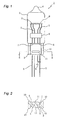
- reference character 1 designates a bulb capsule of a halogen lamp
- reference character 2 stands for a glass bulb which is sealed in such a manner that one end thereof is closed by a pinch seal portion 3 and the other end is closed by an air exhaust portion 4.
- Lead wires 5 are inserted through the pinch seal portion 3, while the intermediate portions of the lead wires 5 are respectively held by the pinch seal portion 3.
- a section of the pinch seal portion side end portion 6 of the glass bulb 2, which is near to the base end of the pinch seal portion 3, is formed larger in thickness than the remaining sections thereof to thereby provide a thick section 7.
- the thick section 7 is formed in such a manner that it projects outwardly (downwardly) of the glass bulb 2, while the lower surface of the thick section 7 is so formed as to be almost at right angles to the pinch seal portion 3.
- Glass bridges 8 are welded in such a manner that they hold the lead wires 5 between them within the glass bulb 2. Filaments 9 are provided between the leading ends of the properly selected ones of the lead wires 5.
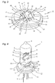
- the pinch seal portion 3 is formed in an substantially flat shape, and includes projecting strips 10 on the two side surfaces thereof which are situated on the two sides thereof in the width direction thereof.
- engaging projection sections 11 which extend in the width direction of the pinch seal portion 3, while the two ends of each of the engaging projection sections 11 are respectively spaced apart from their corresponding projecting strips 10 by a proper clearance.
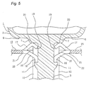
- Reference character 12 stands for a hold plate which is formed of a metal plate having spring elasticity, while it has a substantially circular shape when it is viewed from top. And, the peripheral edge of the hold plate 12 is bent downward stagewise to thereby provide a contact surface 13 facing downward and a staking edge 14 bent downward from the outer peripheral edge of the contact surface 13. Further, when such hold plate 12 is fitted with the outside of a tubular metal member (not shown) and the staking edge 14 thereof is then staked, then there is provided a base body.
- the hold plate 12 includes a hold surface 15 and, in the portions of the hold surface 15 near to the central, portion thereof, there are provided two pairs of pinch seal side hold pieces 16 and two pairs of glass bulb side hold pieces 17, which are respectively formed by cutting and raising their corresponding portions of the hold surface 15.
- the paired pinch seal side hold pieces 16 are formed opposed to each other, are respectively bent from the hold surface 15 in an obliquely downward direction (in Fig. 5, toward the lower edge of the present drawing sheet), and further the leading end portions thereof 18 are respectively bent downward.
- the paired glass bulb side hold pieces 17 are formed opposed to each other, and are respectively bent from the hold surface 15 in an obliquely upward direction, while there are further formed bent portions 20 so that the leading end portions 19 of the glass bulb side hold pieces 17 can be respectively bent in an obliquely downward direction. Also, the distances between the leading end portions of the mutually opposed glass bulb side hold pieces 17 are set slightly larger than the thicknesses of the portions of the pinch seal portion 3 in which no projecting strips are formed.
- a space which is formed due to the formation of the spaces 22 and the above-mentioned respective hold pieces, when viewed from above, can have a substantially I shape which corresponds to the section shape of the pinch seal portion 3 of the bulb capsule 1.
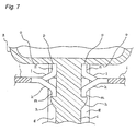
- the pinch seal portion 3 thereof is inserted from above into between the hold pieces 16, 17 of the hold plate 12 until, as can be seen well from Fig. 5, the bent portions 20 of the glass bulb hold pieces 17 are respectively contacted with the thick portion 7 of the pinch seal portion side end portion 6 of the glass bulb 2 as well as the leading end portions 18 of the pinch seal side hold pieces 16 are engaged with the engaging projection sections 11.
- the glass bulb side hold pieces 17 are allowed to slip through between the leading ends of the engaging projections 11 and projections 10 of the pinch seal portion 3 and reach the pinch seal portion side end portion 6 of the glass bulb 2, while the leading end portions 18 of the pinch seal side hold pieces 16 go up onto the engaging projection sections 11 once and, after then, are respectively engaged with the upper sides of the engaging projection sections 11.
- the leading end portions 18 of the pinch seal side hold pieces 16, which are situated below the hold surface 15, are elastically contacted with the side surface of the intermediate portion of the pinch seal portion 3 of the bulb capsule 1 from both sides to thereby hold the pinch seal portion 3. Also, not only the leading end portions 18 of the pinch seal side hold pieces 16 engage with the upper surfaces of the engaging projection sections 11 but also the outer sections of the bent portions 20 of the glass bulb side hold pieces 17 are contacted with the thick portions 7 of the pinch seal portion side end portion 6 of the glass bulb 2, thereby preventing the bulb capsule 1 from being removed from the hold plate 12.
- the portions of the glass bulb 2 with which the glass bulb side hold pieces 17 are contacted are the thick portions 7 formed in the pinch seal portion side end portion 6 of the glass bulb 2, even if stresses caused by the engagement of the glass bulb side hold pieces 17 are concentrated on the present thick portions 7, the present thick portion 7 are able to stand such stresses. Also, because the portions of the glass bulb 2 which engage with the present thick portions 7 are the bent portions 20 of the glass bulb side hold pieces 17, it is possible to prevent the glass bulb 2 against such damage which can occur when the sharp edge portions of the glass bulb hold pieces 17 are engaged with the glass bulb 2.
- leading ends 19 of the glass bulb side hold pieces 17 are formed such that the distances between the mutually opposed ones are slightly larger than the thickness of the pinch seal portion 3, the present leading ends 19 are prevented against contact with the pinch seal portion 3.
- the pinch seal portion side end portion of the glass bulb is structured such that a section thereof, with which the glass bulb side hold pieces of the hold plate can be engaged, is formed larger in thickness than the remaining sections thereof, even if stresses due to the engagement of the glass bulb side hold pieces are concentrated on the present section, the present section is able to stand such concentrated stresses.
- the contact surface of the contact section of the pinch seal portion side end portion of the glass bulb, with which the glass bulb side hold pieces are to engage is formed such that it makes an angle of almost 90 degrees with respect to the pinch seal portion.
- each of the glass bulb side hold pieces is so formed as to have a bent portion, the outer section of the bent portion engages with the pinch seal portion side end portion of the glass bulb, and the leading end of the bent portion is so extended toward the pinch seal portion side as to provide a clearance between the pinch seal portion and itself. Due to this, there is eliminated the possibility that there can be generated any burr in the outer sections of the bent portions of the glass bulb side hold pieces, thereby preventing the pinch seal portion side end portion of the glass bulb against damage. Also, the section of the leading end portion of the glass bulb, in which burrs are produced, is spaced apart from the pinch seal portion, there is also eliminated the danger that the pinch seal portion can be damaged.
Landscapes
- Vessels And Coating Films For Discharge Lamps (AREA)
- Arrangement Of Elements, Cooling, Sealing, Or The Like Of Lighting Devices (AREA)
Applications Claiming Priority (3)
| Application Number | Priority Date | Filing Date | Title |
|---|---|---|---|
| JP20937296 | 1996-07-22 | ||
| JP8209372A JPH1040878A (ja) | 1996-07-22 | 1996-07-22 | 口金付き電球 |
| JP209372/96 | 1996-07-22 |
Publications (3)
| Publication Number | Publication Date |
|---|---|
| EP0821400A2 true EP0821400A2 (de) | 1998-01-28 |
| EP0821400A3 EP0821400A3 (de) | 1999-05-26 |
| EP0821400B1 EP0821400B1 (de) | 2004-04-07 |
Family
ID=16571845
Family Applications (1)
| Application Number | Title | Priority Date | Filing Date |
|---|---|---|---|
| EP97112298A Expired - Lifetime EP0821400B1 (de) | 1996-07-22 | 1997-07-17 | Gesockelte elektrische Lampe |
Country Status (5)
| Country | Link |
|---|---|
| US (1) | US5994825A (de) |
| EP (1) | EP0821400B1 (de) |
| JP (1) | JPH1040878A (de) |
| CN (1) | CN1122298C (de) |
| DE (1) | DE69728479T2 (de) |
Cited By (1)
| Publication number | Priority date | Publication date | Assignee | Title |
|---|---|---|---|---|
| WO2008137695A1 (en) * | 2007-05-04 | 2008-11-13 | Honeywell International Inc. | Halogen burner and receptacle assembly |
Families Citing this family (9)
| Publication number | Priority date | Publication date | Assignee | Title |
|---|---|---|---|---|
| JPH11144689A (ja) * | 1997-11-07 | 1999-05-28 | Koito Mfg Co Ltd | 電 球 |
| US7213258B1 (en) | 1999-06-30 | 2007-05-01 | Bellsouth Intellectual Property Corp. | System and method for managing and controlling data |
| US7441264B2 (en) * | 2002-06-24 | 2008-10-21 | International Business Machines Corporation | Security objects controlling access to resources |
| US20030236996A1 (en) * | 2002-06-24 | 2003-12-25 | International Business Machines Corporation | Security objects controlling timed access to resources |
| US20030236979A1 (en) * | 2002-06-24 | 2003-12-25 | International Business Machines Corporation | Group security objects and concurrent multi-user security objects |
| US20040123146A1 (en) * | 2002-12-19 | 2004-06-24 | International Business Machines Corporation | Security objects with language translation and speech to text conversion |
| DE102004006439A1 (de) * | 2004-02-09 | 2005-08-25 | Patent-Treuhand-Gesellschaft für elektrische Glühlampen mbH | Fahrzeugschweinwerferlampe |
| DE102006060008A1 (de) * | 2006-12-19 | 2008-06-26 | Patent-Treuhand-Gesellschaft für elektrische Glühlampen mbH | Lampe mit verbesserter Quetschungsgeometrie |
| US20080272695A1 (en) * | 2007-05-04 | 2008-11-06 | Osram Sylvania Inc. | Lamp capsule retainer |
Family Cites Families (11)
| Publication number | Priority date | Publication date | Assignee | Title |
|---|---|---|---|---|
| HU169187B (de) * | 1974-07-03 | 1976-10-28 | ||
| DE7526777U (de) * | 1975-08-23 | 1976-06-03 | Philips Patentverwaltung Gmbh, 2000 Hamburg | Elektrische lampe mit sockelplatte |
| US4256989A (en) * | 1978-09-22 | 1981-03-17 | Duro Test Corporation | Incandescent lamp with filament mounting means and socket adaptor |
| EP0061757B1 (de) * | 1981-03-31 | 1986-05-14 | Patent-Treuhand-Gesellschaft für elektrische Glühlampen mbH | Verfahren zur Herstellung einer als Quetschung ausgebildeten Gefässabdichtung für eine elektrische Lampe und Quetschvorrichtung zum Durchführen des Verfahrens |
| JPS6044358U (ja) * | 1983-09-05 | 1985-03-28 | 株式会社小糸製作所 | 口金付電球 |
| US4769574A (en) * | 1986-08-04 | 1988-09-06 | Koito Seisakusho Co., Ltd. | Incandescent lamp with a metal coupling to a plastic lamp base for automotive headlamp and like lighting applications |
| JPH073783B2 (ja) * | 1987-11-30 | 1995-01-18 | 東芝ライテック株式会社 | 高圧ナトリウムランプ |
| JPH01243366A (ja) * | 1988-03-24 | 1989-09-28 | Koito Mfg Co Ltd | 口金付電球 |
| JPH0770306B2 (ja) * | 1988-12-01 | 1995-07-31 | 株式会社小糸製作所 | 口金付電球 |
| DE9017224U1 (de) * | 1990-12-20 | 1991-03-07 | Patent-Treuhand-Gesellschaft für elektrische Glühlampen mbH, 8000 München | Kittlos gesockelte elektrische Lampe |
| US5818154A (en) * | 1994-08-10 | 1998-10-06 | Patent-Treuhand-Gesellschaft Fur Elektrische Gluhlampen Mbh | Halogen incandescent lamp in cementless base |
-
1996
- 1996-07-22 JP JP8209372A patent/JPH1040878A/ja active Pending
-
1997
- 1997-07-17 DE DE69728479T patent/DE69728479T2/de not_active Expired - Fee Related
- 1997-07-17 EP EP97112298A patent/EP0821400B1/de not_active Expired - Lifetime
- 1997-07-21 US US08/897,625 patent/US5994825A/en not_active Expired - Fee Related
- 1997-07-22 CN CN97117807.0A patent/CN1122298C/zh not_active Expired - Fee Related
Cited By (2)
| Publication number | Priority date | Publication date | Assignee | Title |
|---|---|---|---|---|
| WO2008137695A1 (en) * | 2007-05-04 | 2008-11-13 | Honeywell International Inc. | Halogen burner and receptacle assembly |
| US7494262B2 (en) | 2007-05-04 | 2009-02-24 | Honeywell International Inc. | Halogen burner and receptacle assembly |
Also Published As
| Publication number | Publication date |
|---|---|
| EP0821400B1 (de) | 2004-04-07 |
| EP0821400A3 (de) | 1999-05-26 |
| DE69728479T2 (de) | 2004-09-02 |
| CN1122298C (zh) | 2003-09-24 |
| JPH1040878A (ja) | 1998-02-13 |
| CN1172342A (zh) | 1998-02-04 |
| US5994825A (en) | 1999-11-30 |
| DE69728479D1 (de) | 2004-05-13 |
Similar Documents
| Publication | Publication Date | Title |
|---|---|---|
| EP0821400A2 (de) | Gesockelte elektrische Lampe | |
| TWI395682B (zh) | 雨刷片用的接頭元件以及雨刷片 | |
| JP3678751B2 (ja) | 接合剤なしで口金を取付けられたハロゲン電球 | |
| CN102356518A (zh) | 具有导电弹簧元件的接触元件、插接连接器和弹簧元件 | |
| JPS5812706B2 (ja) | 口金ブレ−トを有する電燈 | |
| JPH0869846A (ja) | ランプベース用固定クリップ | |
| EP0996203B1 (de) | Sockel für Keilsockellampe | |
| US6190193B1 (en) | Electrical contact element with a terminal lug and a laterally offset contact zone for use in a lamp socket | |
| US20060066103A1 (en) | Clamp for fastening and connecting tubes | |
| CN1127119C (zh) | 灯泡 | |
| EP0137448B1 (de) | Rahmen aus einem Stück für elektrische Lampe | |
| US4570210A (en) | Vehicle lamp unit and method for an improved supporting arrangement of its light source | |
| JP4507662B2 (ja) | 蛍光灯ソケット | |
| JPH0548388Y2 (de) | ||
| JPS6220135Y2 (de) | ||
| JPH066450Y2 (ja) | 自動車用口金付白熱電球 | |
| JPH0430771Y2 (de) | ||
| CN2201738Y (zh) | 集成电路连接器 | |
| JP3000801B2 (ja) | 流体伝動装置の羽根車の製造方法、流体伝動装置の羽根車、及び位置決め部材 | |
| JPH0331002Y2 (de) | ||
| JPS5855577Y2 (ja) | プラグ用栓刃 | |
| JPH0422538Y2 (de) | ||
| JPS6322611Y2 (de) | ||
| JPH04303551A (ja) | 無口金形電球 | |
| JP3237539B2 (ja) | 口金付き白熱電球 |
Legal Events
| Date | Code | Title | Description |
|---|---|---|---|
| PUAI | Public reference made under article 153(3) epc to a published international application that has entered the european phase |
Free format text: ORIGINAL CODE: 0009012 |
|
| AK | Designated contracting states |
Kind code of ref document: A2 Designated state(s): DE GB NL |
|
| PUAL | Search report despatched |
Free format text: ORIGINAL CODE: 0009013 |
|
| AK | Designated contracting states |
Kind code of ref document: A3 Designated state(s): AT BE CH DE DK ES FI FR GB GR IE IT LI LU MC NL PT SE |
|
| 17P | Request for examination filed |
Effective date: 19990611 |
|
| AKX | Designation fees paid |
Free format text: DE GB NL |
|
| 17Q | First examination report despatched |
Effective date: 20021002 |
|
| GRAP | Despatch of communication of intention to grant a patent |
Free format text: ORIGINAL CODE: EPIDOSNIGR1 |
|
| GRAS | Grant fee paid |
Free format text: ORIGINAL CODE: EPIDOSNIGR3 |
|
| GRAA | (expected) grant |
Free format text: ORIGINAL CODE: 0009210 |
|
| AK | Designated contracting states |
Kind code of ref document: B1 Designated state(s): DE GB NL |
|
| REG | Reference to a national code |
Ref country code: GB Ref legal event code: FG4D |
|
| REF | Corresponds to: |
Ref document number: 69728479 Country of ref document: DE Date of ref document: 20040513 Kind code of ref document: P |
|
| PLBE | No opposition filed within time limit |
Free format text: ORIGINAL CODE: 0009261 |
|
| STAA | Information on the status of an ep patent application or granted ep patent |
Free format text: STATUS: NO OPPOSITION FILED WITHIN TIME LIMIT |
|
| 26N | No opposition filed |
Effective date: 20050110 |
|
| PGFP | Annual fee paid to national office [announced via postgrant information from national office to epo] |
Ref country code: GB Payment date: 20050713 Year of fee payment: 9 |
|
| PGFP | Annual fee paid to national office [announced via postgrant information from national office to epo] |
Ref country code: DE Payment date: 20060713 Year of fee payment: 10 |
|
| PGFP | Annual fee paid to national office [announced via postgrant information from national office to epo] |
Ref country code: NL Payment date: 20060716 Year of fee payment: 10 |
|
| PG25 | Lapsed in a contracting state [announced via postgrant information from national office to epo] |
Ref country code: GB Free format text: LAPSE BECAUSE OF NON-PAYMENT OF DUE FEES Effective date: 20060717 |
|
| GBPC | Gb: european patent ceased through non-payment of renewal fee |
Effective date: 20060717 |
|
| NLV4 | Nl: lapsed or anulled due to non-payment of the annual fee |
Effective date: 20080201 |
|
| PG25 | Lapsed in a contracting state [announced via postgrant information from national office to epo] |
Ref country code: NL Free format text: LAPSE BECAUSE OF NON-PAYMENT OF DUE FEES Effective date: 20080201 Ref country code: DE Free format text: LAPSE BECAUSE OF NON-PAYMENT OF DUE FEES Effective date: 20080201 |