EP0137448B1 - Rahmen aus einem Stück für elektrische Lampe - Google Patents
Rahmen aus einem Stück für elektrische Lampe Download PDFInfo
- Publication number
- EP0137448B1 EP0137448B1 EP84111815A EP84111815A EP0137448B1 EP 0137448 B1 EP0137448 B1 EP 0137448B1 EP 84111815 A EP84111815 A EP 84111815A EP 84111815 A EP84111815 A EP 84111815A EP 0137448 B1 EP0137448 B1 EP 0137448B1
- Authority
- EP
- European Patent Office
- Prior art keywords
- legs
- bending
- frame
- light
- mounting
- Prior art date
- Legal status (The legal status is an assumption and is not a legal conclusion. Google has not performed a legal analysis and makes no representation as to the accuracy of the status listed.)
- Expired - Lifetime
Links
- 238000005452 bending Methods 0.000 claims description 24
- 239000002775 capsule Substances 0.000 claims description 23
- 239000004020 conductor Substances 0.000 claims description 5
- 230000013011 mating Effects 0.000 claims description 5
- 238000004519 manufacturing process Methods 0.000 description 2
- 239000000463 material Substances 0.000 description 2
- 229910001220 stainless steel Inorganic materials 0.000 description 2
- 239000002131 composite material Substances 0.000 description 1
- 238000011161 development Methods 0.000 description 1
- 230000018109 developmental process Effects 0.000 description 1
- 230000008030 elimination Effects 0.000 description 1
- 238000003379 elimination reaction Methods 0.000 description 1
- 230000002349 favourable effect Effects 0.000 description 1
- 229910052736 halogen Inorganic materials 0.000 description 1
- 238000007689 inspection Methods 0.000 description 1
- 239000010935 stainless steel Substances 0.000 description 1
Images

Classifications
-
- H—ELECTRICITY
- H01—ELECTRIC ELEMENTS
- H01K—ELECTRIC INCANDESCENT LAMPS
- H01K1/00—Details
- H01K1/42—Means forming part of the lamp for the purpose of providing electrical connection, or support for, the lamp
- H01K1/44—Means forming part of the lamp for the purpose of providing electrical connection, or support for, the lamp directly applied to, or forming part of, the vessel
-
- H—ELECTRICITY
- H01—ELECTRIC ELEMENTS
- H01K—ELECTRIC INCANDESCENT LAMPS
- H01K1/00—Details
- H01K1/28—Envelopes; Vessels
- H01K1/34—Double wall vessels
-
- Y—GENERAL TAGGING OF NEW TECHNOLOGICAL DEVELOPMENTS; GENERAL TAGGING OF CROSS-SECTIONAL TECHNOLOGIES SPANNING OVER SEVERAL SECTIONS OF THE IPC; TECHNICAL SUBJECTS COVERED BY FORMER USPC CROSS-REFERENCE ART COLLECTIONS [XRACs] AND DIGESTS
- Y02—TECHNOLOGIES OR APPLICATIONS FOR MITIGATION OR ADAPTATION AGAINST CLIMATE CHANGE
- Y02B—CLIMATE CHANGE MITIGATION TECHNOLOGIES RELATED TO BUILDINGS, e.g. HOUSING, HOUSE APPLIANCES OR RELATED END-USER APPLICATIONS
- Y02B20/00—Energy efficient lighting technologies, e.g. halogen lamps or gas discharge lamps
Definitions
- the invention relates to a one-piece frame for mounting a light-source capsule within the outer envelope of an electric lamp comprising a one-piece body formed by means of bending a single sheet of stiff electrically conductive material, said one-piece body having two struts and bridges between said struts to provide support for mounting said light-source capsule thereon and having electrical conductivity to act as a part of an electrical circuit through which electrical power is conveyed to said light-source capsule from an external source, as disclosed by US-A-30 94 640.
- FR-A-11 36 381 discloses a one-piece frame for mounting a light-source capsule within the outer envelope of an electric lamp comprising a one-piece body formed by means of bending a single strand of stiff electrically conductive wire, said one-piece body having two struts and bridges between said struts to provide support for mounting said light-source capsule thereon and having electric conductivity to act as a part of an electrical circuit through which electrical power is conveyed to said light-source capsule from an external source.
- the object underlying the invention is to be seen in not only enabling the manufacture of the lamps in question to be simpler and more economical and to improve the structural and electrical integrity of such lamps but also to simplify and enhance the mounting and securing of the one-piece frames to the outer envelopes of such lamps.
- a one-piece frame for mounting a lightsource capsule within the outer envelope of an electric lamp comprising a one-piece body formed by means of bending a single sheet of stiff electrically conductive material, said one-piece body having two legs and a single bridge between said legs, said body being rigid enough to provide support for mounting said light-source capsule thereon and having electrical conductivity enough to act as a part of an electrical circuit through which electrical power is conveyed to said light-source capsule from an external source, the legs having also lower free ends attached to the outer envelope by clamping means for elastically mounting and locking said frame on said outer envelope.
- a one-piece frame for mounting a light-source capsule within the outer envelope of an electric lamp comprising a one-piece body formed by means of bending a single wire of stiff electrically conducting material, said one-piece body having two legs and a single bridge between said legs, said body being rigid enough to provide support for mounting said light-source capsule thereon and having electrical conductivity enough to act as a part of an electrical circuit through which electrical power is conveyed to said light-source capsule from an external source, the legs having also lower free feet fitting into mating grooves of the outer envelope for elestically mounting and locking said frame on said outer envelope.
- FIG. 1 illustrates frame 2, being the "clamp-on" type.
- Frame 2 has clamps 4 and 6 as means for mounting frame 2 on the outer envelope of the lamp.
- Leg 12 may be longer than leg 14, as shown in the drawing, in which case extension 16 provides a convenient mount for one lead-in wire of the light-source capsule.
- FIG. 2 shows a pre-cut flat blank from which frame 2 can be formed by bending operations only.
- the dashed lines in FIG. 2 show where the bends in the blank should be made. Bends 20, 22 and 24, each made through a right angle, approximately, will form the portion of the frame positioned within the outer envelope. Bends 26, 28 and 30 form the mounting and locking means for leg 12. Likewise, bends 32, 34 and 36 form the mounting and locking means for leg 14.
- Bend 26 is made through a right angle, approximately, with tab 40 protruding away from leg 12.
- Bend 28 is essentially C-shaped with the opening facing leg 12.
- Bend 30 is essentially another C-shaped bend in the reverse direction, i.e., with the opening facing away from leg 12. As shown in FIG. 1, the composite of bends 28 and 30 forms essentially a reverse S-shaped curve. since barbed tip 8 has been pre-cut in this embodiment, leg 12 will be completely formed solely by the described bending operations. In similar manner, bends 32, 34 and 36 may be made in tab 42. thereby completing leg 14.
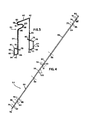
- FIG. 3 illustrates frame 52, being the "push-on" type.
- Frame 52 has legs 54 and 56.
- Loop 58 may be formed as a part of leg 54 in which case loop 58 provides a convenient mount for one lead-in wire of the light-source capsule.
- Loop 58 may be employed by itself or in combination with top 60 as a support for one lead-in wire of the light-source capsule.
- Feet 62 and 64 provide means for mounting frame 52 to the outer envelope of the lamp. Segments 66, 68 and 70 of foot 62 fit into mating grooves of the outer envelope. The segments are held securely within the mating grooves by the mounted lamp base. Likewise, segments 72, 74 and 76 provide mounting means for foot 64. Barbed tips 78 and 80 provide means for locking the lamp base on the outer envelope.
- FIG. 4 shows a pre-cut strand from which frame 52 can be formed by bending operations only.
- the dashed lines in FIG. 4 show where the bends in the strand should be made. All bends are made in the plan determined by legs 54 and 56 except for bends 82 and 98 which are made such that segments 70 and 76 are approximately perpendicular to such plane. The respective directions of segments 70 and 76 are determined by the mating grooves of the outer envelope.
- loop 58 is essentially C-shaped with the opening facing the outside of the frame.
- Bend 100 may comprise a single bend of relatively uniform curvature or it may comprise several bends of varying curvature.
- loop 58 is to provide a mount or an additional mount for one lead-in wire of the light-source capsule. In some embodiments of the invention, loop 58 may not be necessary.
- bend 90 and 92 essentially form top 60 and legs 54 and 56.
- Bends 86, 84 and 82 form foot 62; and bends 94, 96 and 98 form foot 64.
- frames 2 and 52 should have structural rigidity and elasticity so that the frames will securely support the light-source capsule, mount the outer envelope, and lock the lamp base to the outer envelope.
- the material must be electrically conductive, because frames 2 and 52 are part of the electrical circuit of the lamp.
- frame 2 was constructed from a blank of .020 inch (.051 centimeter) thick nickel-plated stainless steel sheet; frame 52 was constructed from a strand of .050 inch (.127 centimeter) diameter stainless steel wire.
- the elimination of fastening joints provides one-piece frames for electric lamps which are easier and cheaper to manufacture, which have improved structural rigidity and precision, and which have improved electrical integrity.
- the one-piece frame disclosed herein provides a suitable component for commercially feasible products.
Landscapes
- Fastening Of Light Sources Or Lamp Holders (AREA)
Claims (4)
- Einstückiger Rahmen (2) für die Montage einer kapselförmigen Lichtquelle innerhalb der äußeren Hülle einer elektrischen Lampe, mit einem einstückigen Körper, der mittels Biegens aus einem einzelnen Blatt steifen, elektrisch leitenden Materials geformt ist, wobei dieser einstückige Körper zwei Stege (12, 14) und eine einzelne Brücke zwischen diesen beiden Stegen aufweist, steif genug ist, um eine Stütze für die Montage der kapselförmigen Lichtquelle auf ihm zu bilden, und genügend elektrische Leitfähigkeit besitzt, um als ein Teil des elektrischen Schaltkreises zu fungieren, durch den elektrische Leistung von einer äußeren Quelle zur kapselförmigen Lichtquelle transportiert wird, und wobei die Stege (12, 14) ferner untere freie Enden aufweisen, die vermöge Klemmelementen an der äußeren Hülle angeordnet sind, um den Rahmen (2) an dieser äußeren Hülle elastisch montiert zu befestigen.
- Rahmen nach Anspruch 1, dadurch gekennzeichnet, daß die unteren Enden derart geformt sind, daß sie die Klemmelemente (4, 6) bilden, und zwar durch ein Biegen ihrer Endteile in eine von den Stegen (12, 14) des Rahmens (2) gebildete Ebene nach außen um näherungsweise 90° von den Stegen (12, 14) weg jeweils nach beiden Seiten längs erster Biegelinien (26, 32), wodurch sich von den Stegen (12, 14) weg erstreckende Laschen (40, 42) gebildet werden, sodann durch Biegen kürzerer Teile dieser Laschen nach oben und einwärts längs zweiter Biegelinien (28, 34), die von den ersten Biegelinien (26, 32) in Abstand angeordnet sind, und schließlich durch Biegen erneut kürzerer Teile der Laschen nach oben und außen längs dritter Biegelinien (30, 36), die von den zweiten Biegelinien (28, 34) in Abstand angeordnet sind.
- Einstückiger Rahmen (52) für die Montage einer kapselförmigen Lichtquelle innerhalb der äußeren Hülle einer elektrischen Lampe, mit einem einstückigen Körper, der mittels Biegens eines einzelnen Drahts aus steifem, elektrisch leitendem Material geformt ist, wobei der einstückige Körper zwei Stege (54, 56) und eine einzelne Brücke (16) zwischen diesen Stegen aufweist und steif genug ist, um eine Stütze für die Montage der kapselförmigen Lichtquelle auf ihm zu bilden, und ferner genügend elektrische Leitfähigkeit besitzt, um als Teil eines elektrischen Schaltkreises zu fungieren, durch den elektrische Leistung von einer äußeren Quelle der kapselförmigen Lichtquelle zugeführt wird, und wobei die Stege (54, 56) außerdem untere freie Füße (62, 64) aufweisen, die zwecks elastischer Montage und Befestigung des Rahmens (52) an der äußeren Hülle in entsprechenden Nuten der äußeren Hülle passen.
- Rahmen nach Anspruch 3, dadurch gekennzeichnet, daß in einem (54) der Stege (54, 65) eine Schleife (58) nahe der Brücke (60) angeordnet ist, wobei diese Schleife sich innerhalb einer von den Stegen (54, 56) des Rahmens (52) gebildeten Ebene einwärts erstreckt, und wobei die unteren Enden der Stege derart geformt sind, daß sie die unteren Füße (62, 64) durch Biegen von Endteilen derselben innerhalb der genannten Ebene nach außen unter näherungsweise rechtem Winkel von den Stegen (54, 56) weg jeweils nach beiden Seiten an ersten Biegungen (86, 94) bilden, wobei sie Endteile (66, 68, 70; 72, 74, 76) formen, die sich von den Stegen (54, 56) weg erstrecken, sodann gekennzeichnet durch das Biegen kürzerer Teile (68, 70; 74, 76) derselben nach oben unter näherungsweise rechtem Winkel an zweiten Biegungen (84; 96), die von den ersten Biegungen (86, 94) in Abstand angeordnet sind, und schließlich Biegen von erneut kürzeren Teilen an dritten Biegungen (82; 98), die von den zweiten Biegungen (84; 96) in Abstand angeordnet sind in entgegengesetzten Richtungen heraus aus und im wesentlichen senkrecht zu der genannten Ebene.
Applications Claiming Priority (2)
| Application Number | Priority Date | Filing Date | Title |
|---|---|---|---|
| US06/539,852 US4500948A (en) | 1983-10-07 | 1983-10-07 | One-piece frame for an electric lamp |
| US539852 | 2000-03-31 |
Publications (3)
| Publication Number | Publication Date |
|---|---|
| EP0137448A2 EP0137448A2 (de) | 1985-04-17 |
| EP0137448A3 EP0137448A3 (en) | 1986-01-22 |
| EP0137448B1 true EP0137448B1 (de) | 1991-07-24 |
Family
ID=24152926
Family Applications (1)
| Application Number | Title | Priority Date | Filing Date |
|---|---|---|---|
| EP84111815A Expired - Lifetime EP0137448B1 (de) | 1983-10-07 | 1984-10-03 | Rahmen aus einem Stück für elektrische Lampe |
Country Status (4)
| Country | Link |
|---|---|
| US (1) | US4500948A (de) |
| EP (1) | EP0137448B1 (de) |
| CA (1) | CA1228632A (de) |
| DE (1) | DE3484836D1 (de) |
Families Citing this family (6)
| Publication number | Priority date | Publication date | Assignee | Title |
|---|---|---|---|---|
| US4779021A (en) * | 1985-05-01 | 1988-10-18 | Gte Products Corporation | Electric lamp with improved self-mounting frame member |
| DE9101460U1 (de) * | 1991-02-08 | 1991-05-02 | Patent-Treuhand-Gesellschaft für elektrische Glühlampen mbH, 8000 München | Einseitig gesockelte elektrische Lampe |
| FR2689829B1 (fr) * | 1992-04-08 | 1998-04-10 | Valeo Vision | Dispositif d'eclairage ou de signalisation pour vehicule automobile, comprenant une lampe navette. |
| US7615930B2 (en) * | 2006-06-26 | 2009-11-10 | Osram Sylvania Inc. | Shrouded arc discharge lamp suitable for downlighting applications |
| US20120014094A1 (en) * | 2010-07-14 | 2012-01-19 | Shenzhen China Star Optoelectronics Technology Co., Ltd. | Connection component and backlight module |
| US10318904B2 (en) | 2016-05-06 | 2019-06-11 | General Electric Company | Computing system to control the use of physical state attainment of assets to meet temporal performance criteria |
Family Cites Families (6)
| Publication number | Priority date | Publication date | Assignee | Title |
|---|---|---|---|---|
| US420607A (en) * | 1890-02-04 | Candle-holder for christmas-trees | ||
| US164599A (en) * | 1875-06-15 | Improvement in clamps for candle-holders | ||
| US2830210A (en) * | 1954-09-16 | 1958-04-08 | Gen Electric | Arc tube support |
| US3094640A (en) * | 1960-12-19 | 1963-06-18 | Sylvania Electric Prod | Harness for supporting high pressure arc discharge tube within outer envelope, and lamp formed thereby |
| US3218495A (en) * | 1962-12-06 | 1965-11-16 | Westinghouse Electric Corp | Arc tube mount and component therefor |
| BR8400762A (pt) * | 1983-02-25 | 1984-10-02 | Gte Prod Corp | Metodo para manufaturar lampada eletrica e lampada assim obtida |
-
1983
- 1983-10-07 US US06/539,852 patent/US4500948A/en not_active Expired - Fee Related
-
1984
- 1984-09-28 CA CA000464360A patent/CA1228632A/en not_active Expired
- 1984-10-03 DE DE8484111815T patent/DE3484836D1/de not_active Expired - Lifetime
- 1984-10-03 EP EP84111815A patent/EP0137448B1/de not_active Expired - Lifetime
Also Published As
| Publication number | Publication date |
|---|---|
| DE3484836D1 (de) | 1991-08-29 |
| EP0137448A3 (en) | 1986-01-22 |
| US4500948A (en) | 1985-02-19 |
| CA1228632A (en) | 1987-10-27 |
| EP0137448A2 (de) | 1985-04-17 |
Similar Documents
| Publication | Publication Date | Title |
|---|---|---|
| CA1145810A (en) | Baseless incandescent lamp assembly | |
| US8920002B2 (en) | Wire-clasping light-emitting diode lights | |
| JP3678751B2 (ja) | 接合剤なしで口金を取付けられたハロゲン電球 | |
| EP0137448B1 (de) | Rahmen aus einem Stück für elektrische Lampe | |
| JPS61153941A (ja) | ランプの金属製口金とガラス製エンベロープの相互接続用プラスチツク製スカート | |
| EP0748516B1 (de) | Elektrische lampe | |
| CA1160435A (en) | Method for manufacturing a baseless incandescent lamp assembly | |
| EP0996203A3 (de) | Metallkontakt für Keilsockellampe | |
| JPH07153436A (ja) | ランプ導入線組立体 | |
| US5229683A (en) | Electric lamp with cementless base | |
| US6190193B1 (en) | Electrical contact element with a terminal lug and a laterally offset contact zone for use in a lamp socket | |
| US4146814A (en) | Pinch and base structure for single-ended lamps | |
| EP0821400A2 (de) | Gesockelte elektrische Lampe | |
| US4061940A (en) | Baseless cartridge lamp and socket therefor | |
| US7745999B2 (en) | Lamp which is closed on two sides | |
| JPH0325881B2 (de) | ||
| GB2029093A (en) | Attachment of caps to press- sealed lamps | |
| JP2523114Y2 (ja) | 電 球 | |
| JPH0427092Y2 (de) | ||
| JPH03225912A (ja) | アルミニウム電解コンデンサ | |
| EP0200199A2 (de) | Elektrische Lampe mit selbstaufstellendem Gestellunterteil | |
| EP1105904B1 (de) | Elektrische lampe | |
| JPS6220135Y2 (de) | ||
| JPS6035982Y2 (ja) | 無口金電球用ソケツト | |
| JPS6340811Y2 (de) |
Legal Events
| Date | Code | Title | Description |
|---|---|---|---|
| PUAI | Public reference made under article 153(3) epc to a published international application that has entered the european phase |
Free format text: ORIGINAL CODE: 0009012 |
|
| 17P | Request for examination filed |
Effective date: 19841003 |
|
| AK | Designated contracting states |
Designated state(s): BE DE FR GB IT NL |
|
| PUAL | Search report despatched |
Free format text: ORIGINAL CODE: 0009013 |
|
| AK | Designated contracting states |
Designated state(s): BE DE FR GB IT NL |
|
| 17Q | First examination report despatched |
Effective date: 19870727 |
|
| GRAA | (expected) grant |
Free format text: ORIGINAL CODE: 0009210 |
|
| AK | Designated contracting states |
Kind code of ref document: B1 Designated state(s): BE DE FR GB IT NL |
|
| PG25 | Lapsed in a contracting state [announced via postgrant information from national office to epo] |
Ref country code: IT Free format text: LAPSE BECAUSE OF FAILURE TO SUBMIT A TRANSLATION OF THE DESCRIPTION OR TO PAY THE FEE WITHIN THE PRESCRIBED TIME-LIMIT;WARNING: LAPSES OF ITALIAN PATENTS WITH EFFECTIVE DATE BEFORE 2007 MAY HAVE OCCURRED AT ANY TIME BEFORE 2007. THE CORRECT EFFECTIVE DATE MAY BE DIFFERENT FROM THE ONE RECORDED. Effective date: 19910724 |
|
| REF | Corresponds to: |
Ref document number: 3484836 Country of ref document: DE Date of ref document: 19910829 |
|
| ET | Fr: translation filed | ||
| PLBE | No opposition filed within time limit |
Free format text: ORIGINAL CODE: 0009261 |
|
| STAA | Information on the status of an ep patent application or granted ep patent |
Free format text: STATUS: NO OPPOSITION FILED WITHIN TIME LIMIT |
|
| 26N | No opposition filed | ||
| PGFP | Annual fee paid to national office [announced via postgrant information from national office to epo] |
Ref country code: BE Payment date: 19920924 Year of fee payment: 9 |
|
| PGFP | Annual fee paid to national office [announced via postgrant information from national office to epo] |
Ref country code: GB Payment date: 19920930 Year of fee payment: 9 |
|
| PGFP | Annual fee paid to national office [announced via postgrant information from national office to epo] |
Ref country code: FR Payment date: 19921029 Year of fee payment: 9 |
|
| PGFP | Annual fee paid to national office [announced via postgrant information from national office to epo] |
Ref country code: NL Payment date: 19921031 Year of fee payment: 9 |
|
| PGFP | Annual fee paid to national office [announced via postgrant information from national office to epo] |
Ref country code: DE Payment date: 19921218 Year of fee payment: 9 |
|
| PG25 | Lapsed in a contracting state [announced via postgrant information from national office to epo] |
Ref country code: GB Effective date: 19931003 |
|
| PG25 | Lapsed in a contracting state [announced via postgrant information from national office to epo] |
Ref country code: BE Effective date: 19931031 |
|
| BERE | Be: lapsed |
Owner name: GTE PRODUCTS CORP. Effective date: 19931031 |
|
| PG25 | Lapsed in a contracting state [announced via postgrant information from national office to epo] |
Ref country code: NL Effective date: 19940501 |
|
| GBPC | Gb: european patent ceased through non-payment of renewal fee |
Effective date: 19931003 |
|
| NLV4 | Nl: lapsed or anulled due to non-payment of the annual fee | ||
| PG25 | Lapsed in a contracting state [announced via postgrant information from national office to epo] |
Ref country code: FR Effective date: 19940630 |
|
| PG25 | Lapsed in a contracting state [announced via postgrant information from national office to epo] |
Ref country code: DE Effective date: 19940701 |
|
| REG | Reference to a national code |
Ref country code: FR Ref legal event code: ST |