EP0821182B1 - Transmission manuelle compacte à engrenages pour automobiles - Google Patents
Transmission manuelle compacte à engrenages pour automobiles Download PDFInfo
- Publication number
- EP0821182B1 EP0821182B1 EP97112574A EP97112574A EP0821182B1 EP 0821182 B1 EP0821182 B1 EP 0821182B1 EP 97112574 A EP97112574 A EP 97112574A EP 97112574 A EP97112574 A EP 97112574A EP 0821182 B1 EP0821182 B1 EP 0821182B1
- Authority
- EP
- European Patent Office
- Prior art keywords
- gear
- speed
- intermediate shaft
- input
- synchronizer clutch
- Prior art date
- Legal status (The legal status is an assumption and is not a legal conclusion. Google has not performed a legal analysis and makes no representation as to the accuracy of the status listed.)
- Expired - Lifetime
Links
Images


Classifications
-
- F—MECHANICAL ENGINEERING; LIGHTING; HEATING; WEAPONS; BLASTING
- F16—ENGINEERING ELEMENTS AND UNITS; GENERAL MEASURES FOR PRODUCING AND MAINTAINING EFFECTIVE FUNCTIONING OF MACHINES OR INSTALLATIONS; THERMAL INSULATION IN GENERAL
- F16H—GEARING
- F16H3/00—Toothed gearings for conveying rotary motion with variable gear ratio or for reversing rotary motion
- F16H3/02—Toothed gearings for conveying rotary motion with variable gear ratio or for reversing rotary motion without gears having orbital motion
- F16H3/08—Toothed gearings for conveying rotary motion with variable gear ratio or for reversing rotary motion without gears having orbital motion exclusively or essentially with continuously meshing gears, that can be disengaged from their shafts
- F16H3/087—Toothed gearings for conveying rotary motion with variable gear ratio or for reversing rotary motion without gears having orbital motion exclusively or essentially with continuously meshing gears, that can be disengaged from their shafts characterised by the disposition of the gears
- F16H3/093—Toothed gearings for conveying rotary motion with variable gear ratio or for reversing rotary motion without gears having orbital motion exclusively or essentially with continuously meshing gears, that can be disengaged from their shafts characterised by the disposition of the gears with two or more countershafts
- F16H2003/0931—Toothed gearings for conveying rotary motion with variable gear ratio or for reversing rotary motion without gears having orbital motion exclusively or essentially with continuously meshing gears, that can be disengaged from their shafts characterised by the disposition of the gears with two or more countershafts each countershaft having an output gear meshing with a single common gear on the output shaft
-
- F—MECHANICAL ENGINEERING; LIGHTING; HEATING; WEAPONS; BLASTING
- F16—ENGINEERING ELEMENTS AND UNITS; GENERAL MEASURES FOR PRODUCING AND MAINTAINING EFFECTIVE FUNCTIONING OF MACHINES OR INSTALLATIONS; THERMAL INSULATION IN GENERAL
- F16H—GEARING
- F16H2200/00—Transmissions for multiple ratios
- F16H2200/003—Transmissions for multiple ratios characterised by the number of forward speeds
- F16H2200/0047—Transmissions for multiple ratios characterised by the number of forward speeds the gear ratios comprising five forward speeds
-
- Y—GENERAL TAGGING OF NEW TECHNOLOGICAL DEVELOPMENTS; GENERAL TAGGING OF CROSS-SECTIONAL TECHNOLOGIES SPANNING OVER SEVERAL SECTIONS OF THE IPC; TECHNICAL SUBJECTS COVERED BY FORMER USPC CROSS-REFERENCE ART COLLECTIONS [XRACs] AND DIGESTS
- Y10—TECHNICAL SUBJECTS COVERED BY FORMER USPC
- Y10T—TECHNICAL SUBJECTS COVERED BY FORMER US CLASSIFICATION
- Y10T74/00—Machine element or mechanism
- Y10T74/19—Gearing
- Y10T74/19219—Interchangeably locked
- Y10T74/19223—Disconnectable counter shaft
-
- Y—GENERAL TAGGING OF NEW TECHNOLOGICAL DEVELOPMENTS; GENERAL TAGGING OF CROSS-SECTIONAL TECHNOLOGIES SPANNING OVER SEVERAL SECTIONS OF THE IPC; TECHNICAL SUBJECTS COVERED BY FORMER USPC CROSS-REFERENCE ART COLLECTIONS [XRACs] AND DIGESTS
- Y10—TECHNICAL SUBJECTS COVERED BY FORMER USPC
- Y10T—TECHNICAL SUBJECTS COVERED BY FORMER US CLASSIFICATION
- Y10T74/00—Machine element or mechanism
- Y10T74/19—Gearing
- Y10T74/19219—Interchangeably locked
- Y10T74/19233—Plurality of counter shafts
-
- Y—GENERAL TAGGING OF NEW TECHNOLOGICAL DEVELOPMENTS; GENERAL TAGGING OF CROSS-SECTIONAL TECHNOLOGIES SPANNING OVER SEVERAL SECTIONS OF THE IPC; TECHNICAL SUBJECTS COVERED BY FORMER USPC CROSS-REFERENCE ART COLLECTIONS [XRACs] AND DIGESTS
- Y10—TECHNICAL SUBJECTS COVERED BY FORMER USPC
- Y10T—TECHNICAL SUBJECTS COVERED BY FORMER US CLASSIFICATION
- Y10T74/00—Machine element or mechanism
- Y10T74/19—Gearing
- Y10T74/19219—Interchangeably locked
- Y10T74/19377—Slidable keys or clutches
- Y10T74/19386—Multiple clutch shafts
- Y10T74/194—Selective
Definitions
- This invention relates to a manual transmission according to the generic part of the independent claim.
- a transmission of this kind is described in "Design Engineering", 1 July 1992, Page 19.
- Gearsets on both countershafts can be selectively engaged to deliver power from the input shaft to the axle half-shafts.
- US-A-5 385 065 and 5 495 775 disclose five-speed transaxles having a synchronized reverse gear arrangement.
- the problem to be solved by the present invention is to provide a multi-speed manual transaxle that meets the above-noted needs and improves upon conventional designs.
- the input gear for establishing a fourth speed ratio is rotatably supported on the second intermediate shaft in addition to the fifth speed gear and the reverse gear.
- This allows for employing a shorter input shaft, and therefore the transmission can be more compact in its length direction.
- none of the synchronization clutches is linked to the input shaft; instead they are strictly associated with the intermediate shafts.
- the third input gear drives also the fourth speed gear so that the total number of gears employed is smaller than in the prior art transmission.
- Transaxle 10 is shown that is adapted for use in front wheel drive motor vehicles.
- Transaxle 10 is a five-speed arrangement having all of its forward and reverse gears synchronized and yet is efficiently packaged to provide a compact gearbox.
- transaxle 10 is shown to include a housing 12 within which an input shaft 14 is rotatably supported by bearings 16 and 18 for rotation about a first axis "A".
- input shaft 14 is adapted to be driven through a suitable manually-released clutch (not shown) by the vehicles's engine.
- Transaxle 10 is also shown to include a first driven or intermediate shaft 20 rotatably supported in housing 12 by bearings 22 and 24 for rotation about second axis "B", a second driven or intermediate shaft 26 rotatably supported in housing 12 by bearings 28 and 30 for rotation about a third axis "C”, and a differential 32 supported in housing 12 by bearings 34 and 36 for rotation about a fourth axis "D".
- the output of differential 32 includes a pair of axially-aligned side gears 38 to which axle half-shafts 40 are fixed so as to connect differential 32 to the driving wheels of the motor vehicle.
- the input to differential 32 is a final drive gear 42 fixed to differential cage 44 and which is in constant meshed engagement with a first transfer gear 46 fixed to first intermediate shaft 20 as well as with a second transfer gear 48 fixed to second intermediate shaft 26.
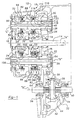
- FIG. 1 is a so-called "unrolled" sectional view wherein shafts 14, 20, 26 and 40 are all arranged in a single plane. However, in reality, these shafts are compactly arranged in a parallel relationship relative to each other, with no three shafts aligned in a common plane, as is shown in FIG. 3. In this manner, the center distances between the shafts can be effectively minimized.
- Transaxle 10 includes a series of constant-mesh gearsets 50, 52, 54, 56, 58 and 60 that can be selectively engaged for establishing five forward speed ratios as well as a reverse speed ratio between input shaft 14 and final drive gear 42.
- Gearset 50 includes a first input gear 62 fixed to input shaft 14 and a first speed gear 64 rotatably supported on first intermediate shaft 20.
- First speed gear 64 is in constant mesh with first input gear 62 for defining a first power transmission path that can be selectively engaged to establish a first forward speed ratio.
- Gearset 52 includes a second input gear 66 fixed to input shaft 14 that is in constant mesh with a second speed gear 68 rotatably supported on first intermediate shaft 20.
- gearset 52 functions to define a second power transmission path that can be selectively engaged to establish a second forward speed ratio.
- Gearset 54 includes a third input gear 70 fixed to input shaft 14 that is in constant mesh with a third speed gear 72 rotatably supported on second intermediate shaft 26. As such, gearset 54 functions to define a third power transmission path that can be selectively engaged to establish a third forward speed ratio.
- Gearset 56 includes a fourth speed gear 74 rotatably supported on first intermediate shaft 20 that is also in constant mesh with third input gear 70.
- gearset 56 functions to define a fourth power transmission path that can be selectively engaged to establish a fourth forward speed ratio.
- Gearset 58 includes a fourth input gear 76 fixed to input shaft 14 that is in constant mesh with a fifth speed gear 78 rotatably supported on second intermediate shaft 26.
- Gearset 56 functions to define a fifth power transmission path that can be selectively engaged to establish a fifth forward speed ratio.
- gearset 60 includes a reverse gear 80 rotatably supported on second intermediate shaft 26 that is in constant mesh with first speed gear 64. As such, gearset 60 defines a sixth power transmission path that can be selectively engaged to establish the reverse speed ratio.
- each gearset is associated with a synchronizer clutch.
- a first synchronizer clutch 82 is operably located between first and second speed gears 64 and 68 and includes a hub 84 fixed to first intermediate shaft 20, a shift sleeve 86 mounted for rotation with and axial sliding movement on hub 84, and a pair of suitable blocker-type synchronizers 88 interposed between shift sleeve 86 and speed gears 64 and 68.
- First synchronizer clutch 82 is of the double-acting variety such that forward axial movement of shift sleeve 86 from its centered neutral position shown is adapted to couple first speed gear 64 to first intermediate shaft 20 for establishing the first forward speed ratio in which first transfer gear 46 drives final drive gear 42. Moreover, rearward axial movement of shift sleeve 86 from its neutral position is adapted to couple second speed gear 68 to first intermediate shaft 20 such that first transfer gear 46 drives final drive gear 42 at the second forward speed ratio.
- a second synchronizer clutch 88 is located adjacent to third speed gear 72 and includes a hub 90 fixed to second intermediate shaft 26, a shift sleeve 92 mounted for rotation with and axial sliding movement on hub 90, and a blocker-type synchronizer 94 interposed between shift sleeve 92 and a clutch gear 96 fixed to third speed gear 72.
- Second synchronizer clutch 88 is of the single-acting type such that rearward movement of shift sleeve 92 from its centered neutral position shown is adapted to couple third speed gear 72 to second intermediate shaft 26 such that second transfer gear 48 drives final drive gear 42 at the third speed ratio.
- a third synchronizer clutch 98 is located adjacent to fourth speed gear 74 and includes a hub 100 fixed to first intermediate shaft 20, a shift sleeve 102 mounted for rotation with and axially sliding movement on hub 100, and a blocker-type synchronizer 104 interposed between shift sleeve 102 and a clutch gear 106 fixed to fourth speed gear 74. Rearward sliding movement of shift sleeve 102 from its centered neutral position shown causes it to couple fourth speed gear 74 to first intermediate shaft 20 such that first transfer gear 46 drives final drive gear 42 at the fourth forward speed ratio.
- fourth synchronizer clutch 110 also of the double-acting variety, that is located between fifth speed gear 78 and reverse gear 80.
- Fourth synchronizer clutch 110 includes a hub 112 fixed to second intermediate shaft 26, a shift sleeve 114 mounted for rotation with and axial sliding movement on hub 112, and a pair of blocker-type synchronizers 116 interposed between shift sleeve 114 and gears 78 and 80. Rearward sliding movement of shift sleeve 114 from its centered neutral position shown is adapted to couple a clutch gear 118 fixed to fifth speed gear 78 to second intermediate shaft 26 such that second transfer gear 48 drives final drive gear 42 at the fifth speed ratio.
- shift sleeve 114 In contrast, forward sliding movement of shift sleeve 114 from its neutral position couples it to a clutch gear 120 fixed to reverse gear 80 such that reverse gear 80 is releasably coupled to second intermediate shaft 26.
- second transfer gear 48 drives final drive gear 42 at the reverse speed ratio and in the opposite direction with respect to the normal direction of rotation of final drive gear 42 during forward operation.
- This reversal of direction results from reverse gear 80 being driven by first speed gear 64 which, in turn, is driven by first input gear 62.
- first forward gear torque is delivered from input shaft 14 to differential 32 through elements 62, 64, 86, 84, 20, 46 and 42.
- second forward gear torque is delivered from input shaft 14 to differential 32 through elements 66, 68, 86, 84, 20, 46 and 42.
- third forward gear torque is delivered from input shaft 14 to differential 32 through elements 70, 72, 92, 90, 26, 48 and 42.
- fourth forward gear torque is delivered from input shaft 14 to differential 32 through elements 70, 74, 102, 100, 20, 46 and 42.
- torque is delivered from input shaft 14 to differential 32 through elements 76, 78, 114, 112, 26, 48 and 42.
- FIG. 3 is a schematic illustration of the arrangement of shafts 14, 20, 26 and 40 and of the meshing of the various gearsets.
- a shift pattern or gate diagram for transaxle 10 is shown in FIG. 4.
- any suitable shift system coupling each of shift sleeves 86, 42, 102 and 114 to a gearshift lever (not shown) for coordinated movement to establish the various forward and reverse gears can be used with transaxle 10.
Landscapes
- Engineering & Computer Science (AREA)
- General Engineering & Computer Science (AREA)
- Mechanical Engineering (AREA)
- Structure Of Transmissions (AREA)
Claims (6)
- Transmission manuelle comprenant :caractérisé parun arbre d'entrée (14) ;un premier arbre intermédiaire (20) comportant un premier engrenage de transfert (46) fixé à celui-ci ;un premier engrenage d'entrée (62) fixé audit arbre d'entrée (14) ;un engrenage de première vitesse (64) supporté mobile en rotation sur ledit premier arbre intermédiaire (20) et engrené avec ledit premier engrenage d'entrée (62) de façon à établir un premier rapport de vitesse ;un deuxième engrenage d'entrée (66) fixé audit arbre d'entrée (14) ;un engrenage de deuxième vitesse (68) supporté mobile en rotation sur ledit premier arbre intermédiaire (20) et engrené avec ledit deuxième engrenage d'entrée (66) de façon à établir un deuxième rapport de vitesse ;un premier embrayage synchroniseur (82) destiné à coupler sélectivement l'un ou l'autre desdits engrenages de première (64) et de deuxième (68) vitesse audit premier arbre intermédiaire (20) ;un troisième engrenage d'entrée (70) sur ledit arbre d'entrée (14) ;un engrenage de troisième vitesse (74) sur ledit premier arbre intermédiaire (20) engrené avec ledit troisième engrenage d'entrée (70) ;un deuxième embrayage synchroniseur (98) destiné à établir un troisième rapport de vitesse ;un deuxième arbre intermédiaire (26) comportant un deuxième engrenage de transfert (48) fixé à celui-ci ;un engrenage de quatrième vitesse (72) destiné à établir un quatrième rapport de vitesse ;un embrayage synchroniseur (88) destiné à établir ledit quatrième rapport de vitesse ;un quatrième engrenage d'entrée (76) fixé audit arbre d'entrée (14) ;un engrenage de cinquième vitesse (78) supporté mobile en rotation sur ledit deuxième arbre intermédiaire (26) et engrené avec ledit quatrième engrenage d'entrée (76) ;un engrenage de marche arrière (80) supporté mobile en rotation sur ledit deuxième arbre intermédiaire (26) et engrené avec ledit engrenage de première vitesse (64) ;un autre embrayage synchroniseur (110) destiné à coupler sélectivement l'un ou l'autre dudit engrenage de cinquième vitesse (78) et dudit engrenage de marche arrière (80) audit deuxième arbre intermédiaire (26) ; etun engrenage d'entraínement final (42) engrené avec lesdits premier (46) et deuxième (48) engrenages de transfert ;ledit troisième engrenage d'entrée (70) étant fixé audit arbre d'entrée (14) ;ledit engrenage de troisième vitesse (74) étant supporté mobile en rotation sur ledit premier arbre intermédiaire (20) ;ledit deuxième embrayage synchroniseur (98) couplant sélectivement ledit engrenage de troisième vitesse (74) audit premier arbre intermédiaire (20) ;ledit engrenage de quatrième vitesse (72) étant supporté mobile en rotation sur ledit deuxième arbre intermédiaire (26) et engrené avec ledit troisième engrenage d'entrée (70);ledit un embrayage synchroniseur (88) étant un troisième embrayage synchroniseur et couplant sélectivement ledit engrenage de quatrième vitesse (72) audit deuxième arbre intermédiaire (26) ;ledit autre embrayage synchroniseur (110) étant un quatrième embrayage synchroniseur.
- Transmission manuelle selon la revendication 1, comprenant en outre un différentiel (32) entraíné par ledit engrenage d'entraínement final (42).
- Transmission manuelle selon la revendication 1 ou 2, dans laquelle ledit premier embrayage synchroniseur (82) comprend un premier manchon de changement de vitesse (84) monté de façon à pouvoir être mis en rotation avec ledit premier arbre intermédiaire (20) et mobile depuis une position neutre dans une première direction, afin de mettre en prise sélectivement ledit engrenage de première vitesse (64) en vue d'établir un premier rapport de vitesse de marche avant, et dans laquelle ledit premier manchon de changement de vitesse (84) est mobile dans une deuxième direction depuis sa position neutre afin de mettre en prise sélectivement ledit engrenage de deuxième vitesse (68) en vue d'établir un deuxième rapport de vitesse de marche avant.
- Transmission manuelle selon l'une quelconque des revendications 1, 2, ou 3, dans laquelle ledit deuxième embrayage synchroniseur (98) comprend un deuxième manchon de changement de vitesse (100) monté de façon à pouvoir être mis en rotation avec ledit premier arbre intermédiaire (20) et mobile depuis une position neutre dans une première direction, afin de mettre en prise sélectivement ledit engrenage de troisième vitesse (74) en vue d'établir un troisième rapport de vitesse, et dans laquelle ledit troisième embrayage synchroniseur (88) comprend un troisième manchon de changement de vitesse (90) monté de façon à pouvoir être mis en rotation avec ledit deuxième arbre intermédiaire et mobile depuis une position neutre dans une première direction, afin de mettre en prise sélectivement ledit engrenage de quatrième vitesse (72) en vue d'établir un quatrième rapport de vitesse de marche avant.
- Transmission manuelle selon la revendication 4, dans laquelle ledit quatrième rapport de vitesse de marche avant est inférieur audit troisième rapport de vitesse de marche avant.
- Transmission manuelle selon la revendication 4 ou 5, dans laquelle ledit quatrième embrayage synchroniseur (110) comprend un quatrième manchon de changement de vitesse (112) monté de façon à pouvoir être mis en rotation avec ledit deuxième arbre intermédiaire (26) et mobile depuis une position neutre dans une première direction, afin de mettre en prise sélectivement ledit engrenage de cinquième vitesse (78) en vue d'établir un cinquième rapport de vitesse de marche avant, et dans laquelle ledit quatrième manchon de changement de vitesse (112) est mobile depuis ladite position neutre dans une deuxième direction, afin de mettre en prise sélectivement ledit engrenage de marche arrière (80) en vue d'établir un rapport d'engrenage de marche arrière.
Applications Claiming Priority (2)
| Application Number | Priority Date | Filing Date | Title |
|---|---|---|---|
| US08/681,059 US5704247A (en) | 1996-07-22 | 1996-07-22 | Compact manual transaxle for motor vehicles |
| US681059 | 1996-07-22 |
Publications (2)
| Publication Number | Publication Date |
|---|---|
| EP0821182A1 EP0821182A1 (fr) | 1998-01-28 |
| EP0821182B1 true EP0821182B1 (fr) | 2001-10-24 |
Family
ID=24733646
Family Applications (1)
| Application Number | Title | Priority Date | Filing Date |
|---|---|---|---|
| EP97112574A Expired - Lifetime EP0821182B1 (fr) | 1996-07-22 | 1997-07-22 | Transmission manuelle compacte à engrenages pour automobiles |
Country Status (8)
| Country | Link |
|---|---|
| US (2) | US5704247A (fr) |
| EP (1) | EP0821182B1 (fr) |
| AR (1) | AR007744A1 (fr) |
| AT (1) | ATE207584T1 (fr) |
| BR (1) | BR9704050A (fr) |
| CA (1) | CA2211086C (fr) |
| DE (1) | DE69707589T2 (fr) |
| MX (1) | MX9705530A (fr) |
Families Citing this family (17)
| Publication number | Priority date | Publication date | Assignee | Title |
|---|---|---|---|---|
| US5845531A (en) * | 1997-03-18 | 1998-12-08 | New Venture Gear, Inc. | Multi-speed manual transmission with reverse brake |
| US6023987A (en) * | 1998-03-19 | 2000-02-15 | New Venture Gear, Inc. | Six-speed manual transaxle |
| US6067870A (en) * | 1999-02-26 | 2000-05-30 | New Venture Gear, Inc. | Manual transaxle |
| FR2805221B1 (fr) * | 2000-02-18 | 2002-06-07 | Peugeot Citroen Automobiles Sa | Systeme de transmission de mouvement pour vehicule a propulsion hybride |
| US6397692B1 (en) * | 2000-02-18 | 2002-06-04 | Daimlerchrysler Corporation | Electro-mechanical automatic transmission for front wheel drive |
| US6422103B1 (en) | 2000-06-26 | 2002-07-23 | New Venture Gear, Inc. | Compact front wheel drive six-speed transaxle |
| JP4336448B2 (ja) * | 2000-09-06 | 2009-09-30 | 本田技研工業株式会社 | 平行3軸式自動変速機 |
| US7191676B2 (en) * | 2002-09-23 | 2007-03-20 | Vladimir Abramov | Universal multifarious gearbox of mutually definite units and method therefore |
| DE10302258A1 (de) * | 2003-01-22 | 2004-08-12 | Zf Friedrichshafen Ag | Schaltgetriebe für ein Kraftfahrzeug |
| DE10323721A1 (de) * | 2003-05-24 | 2004-12-23 | Daimlerchrysler Ag | Dreiwellen-Getriebe |
| DE102004056936B4 (de) * | 2004-11-23 | 2011-02-03 | Getrag Getriebe- Und Zahnradfabrik Hermann Hagenmeyer Gmbh & Cie Kg | Stufenwechselgetriebe für ein Kraftfahrzeug |
| GB0516726D0 (en) * | 2005-08-15 | 2005-09-21 | Ricardo Uk Ltd | Twin layshaft transmission |
| US8011274B2 (en) * | 2006-08-28 | 2011-09-06 | Vladimir Abramov | Gear box apparatus |
| CA2670248C (fr) * | 2008-07-01 | 2017-02-07 | Magna Powertrain Usa, Inc. | Axe transversal a plusieurs vitesses a double embrayage |
| US8708105B2 (en) * | 2010-07-27 | 2014-04-29 | GM Global Technology Operations LLC | Transmission with splash lubrication system |
| KR101235554B1 (ko) * | 2010-12-03 | 2013-02-20 | 현대자동차주식회사 | 자동차의 수동 변속기 |
| WO2023233429A1 (fr) * | 2022-06-02 | 2023-12-07 | Mahindra & Mahindra Limited | Chaîne cinématique pour un véhicule |
Family Cites Families (19)
| Publication number | Priority date | Publication date | Assignee | Title |
|---|---|---|---|---|
| US4033200A (en) * | 1975-04-24 | 1977-07-05 | Ford Motor Company | Five speed overdrive transmission |
| US4174644A (en) * | 1978-04-03 | 1979-11-20 | General Motors Corporation | Transmission and shift linkage |
| US4463622A (en) * | 1980-01-11 | 1984-08-07 | Deere & Company | Transmission and reverse gear synchronizing therefor |
| AU7366581A (en) * | 1980-08-14 | 1982-02-18 | Automotive Products Ltd. | Transmission |
| US4461188A (en) * | 1981-12-23 | 1984-07-24 | Ford Motor Company | Dual clutch multiple countershaft transmission |
| US4738150A (en) * | 1982-08-09 | 1988-04-19 | Borg-Warner Corporation | Compact manual transaxle transmission |
| DE3320494A1 (de) * | 1983-06-07 | 1984-12-13 | Getrag Getriebe- Und Zahnradfabrik Gmbh, 7140 Ludwigsburg | Wechselgetriebe mit synchronisiertem rueckwaertsgang |
| SE451005B (sv) * | 1985-03-28 | 1987-08-24 | Volvo Ab | Motorfordonsvexellada |
| SE448359B (sv) * | 1985-07-01 | 1987-02-16 | Volvo Ab | Motorfordonsvexellada |
| FR2605377B2 (fr) * | 1985-10-25 | 1993-11-26 | Renault | Boite de vitesses mecanique a un arbre primaire et a deux arbres secondaires |
| SE454073B (sv) * | 1986-03-17 | 1988-03-28 | Volvo Ab | Motorfordonsvexellada |
| US4780998A (en) * | 1987-01-29 | 1988-11-01 | American Woodwork Specialty Co., Inc. | Decorative window assembly |
| SE467574B (sv) * | 1990-12-10 | 1992-08-10 | Volvo Ab | Stegvaexlad automatvaexellaada foer motorfordon |
| DE4136455C2 (de) * | 1991-11-06 | 1997-02-27 | Getrag Getriebe Zahnrad | Sechsgang-Zahnradwechselgetriebe |
| DE4207989A1 (de) * | 1992-03-13 | 1993-09-16 | Ford Werke Ag | Mehrgaengiges wechselgetriebe fuer kraftfahrzeuge |
| US5357821A (en) * | 1993-04-13 | 1994-10-25 | General Motors Corporation | Transmission and shift control |
| DE4320318C2 (de) * | 1993-06-18 | 1996-12-12 | Getrag Getriebe Zahnrad | Mehrgang-Stufengetriebe |
| SE502418C2 (sv) * | 1993-07-07 | 1995-10-16 | Volvo Ab | Motorfordonsväxellåda |
| US5479835A (en) * | 1994-08-09 | 1996-01-02 | Transmisiones Y Equipos Mecanicos, S.A. De C.V. | Reverse gear synchronizer |
-
1996
- 1996-07-22 US US08/681,059 patent/US5704247A/en not_active Expired - Fee Related
-
1997
- 1997-07-21 CA CA002211086A patent/CA2211086C/fr not_active Expired - Fee Related
- 1997-07-21 AR ARP970103259A patent/AR007744A1/es unknown
- 1997-07-22 DE DE69707589T patent/DE69707589T2/de not_active Expired - Fee Related
- 1997-07-22 EP EP97112574A patent/EP0821182B1/fr not_active Expired - Lifetime
- 1997-07-22 AT AT97112574T patent/ATE207584T1/de active
- 1997-07-22 BR BR9704050-9A patent/BR9704050A/pt not_active IP Right Cessation
- 1997-07-22 MX MX9705530A patent/MX9705530A/es not_active IP Right Cessation
- 1997-08-04 US US08/905,690 patent/US5927145A/en not_active Expired - Fee Related
Also Published As
| Publication number | Publication date |
|---|---|
| DE69707589T2 (de) | 2002-06-27 |
| AR007744A1 (es) | 1999-11-10 |
| US5704247A (en) | 1998-01-06 |
| US5927145A (en) | 1999-07-27 |
| CA2211086C (fr) | 2005-05-31 |
| CA2211086A1 (fr) | 1998-01-22 |
| ATE207584T1 (de) | 2001-11-15 |
| EP0821182A1 (fr) | 1998-01-28 |
| BR9704050A (pt) | 2001-11-27 |
| MX9705530A (es) | 1998-02-28 |
| DE69707589D1 (de) | 2001-11-29 |
Similar Documents
| Publication | Publication Date | Title |
|---|---|---|
| US7077025B2 (en) | Dual clutch automatic transaxle | |
| JP2520353B2 (ja) | 自動車用変速機 | |
| EP0821182B1 (fr) | Transmission manuelle compacte à engrenages pour automobiles | |
| US5722291A (en) | Manual transmission with synchronized reverse gear | |
| US8479604B2 (en) | Powertrain for an automotive vehicle with multiple-ratio gearing and a dual power input clutch | |
| JPH05209661A (ja) | 自動車用歯車変速機 | |
| EP1031762B1 (fr) | Boite-pont manuelle | |
| EP0837263B1 (fr) | Boíte de vitesses à plusieurs rapports à commande manuelle | |
| MXPA97005530A (es) | Eje de transmision manual compacto para vehiculos motrices | |
| CA1061603A (fr) | Transmission manuelle compacte pour moteur transversal | |
| US5697250A (en) | Compact manual transaxle | |
| EP1062436B1 (fr) | Boite-pont manuelle a six vitesses | |
| US5743141A (en) | Compact transaxle | |
| US6422103B1 (en) | Compact front wheel drive six-speed transaxle | |
| US5983741A (en) | Reverse gear assembly of a transmission | |
| MXPA97005531A (es) | Eje de transmision manual compacto | |
| JPH03117749A (ja) | 変速装置 | |
| JP2632757B2 (ja) | 補助変速装置付変速機 | |
| JPH02134439A (ja) | 歯車変速機 |
Legal Events
| Date | Code | Title | Description |
|---|---|---|---|
| PUAI | Public reference made under article 153(3) epc to a published international application that has entered the european phase |
Free format text: ORIGINAL CODE: 0009012 |
|
| AK | Designated contracting states |
Kind code of ref document: A1 Designated state(s): AT BE CH DE DK ES FI FR GB GR IE IT LI LU MC NL PT SE |
|
| AX | Request for extension of the european patent |
Free format text: AL;LT;LV;RO;SI |
|
| 17P | Request for examination filed |
Effective date: 19980603 |
|
| RBV | Designated contracting states (corrected) |
Designated state(s): AT BE CH DE DK ES FI FR GB GR IE IT LI LU MC NL PT SE |
|
| 17Q | First examination report despatched |
Effective date: 19991126 |
|
| GRAG | Despatch of communication of intention to grant |
Free format text: ORIGINAL CODE: EPIDOS AGRA |
|
| GRAG | Despatch of communication of intention to grant |
Free format text: ORIGINAL CODE: EPIDOS AGRA |
|
| GRAH | Despatch of communication of intention to grant a patent |
Free format text: ORIGINAL CODE: EPIDOS IGRA |
|
| GRAH | Despatch of communication of intention to grant a patent |
Free format text: ORIGINAL CODE: EPIDOS IGRA |
|
| GRAA | (expected) grant |
Free format text: ORIGINAL CODE: 0009210 |
|
| AK | Designated contracting states |
Kind code of ref document: B1 Designated state(s): AT BE CH DE DK ES FI FR GB GR IE IT LI LU MC NL PT SE |
|
| PG25 | Lapsed in a contracting state [announced via postgrant information from national office to epo] |
Ref country code: NL Free format text: LAPSE BECAUSE OF FAILURE TO SUBMIT A TRANSLATION OF THE DESCRIPTION OR TO PAY THE FEE WITHIN THE PRESCRIBED TIME-LIMIT Effective date: 20011024 Ref country code: LI Free format text: LAPSE BECAUSE OF FAILURE TO SUBMIT A TRANSLATION OF THE DESCRIPTION OR TO PAY THE FEE WITHIN THE PRESCRIBED TIME-LIMIT Effective date: 20011024 Ref country code: IT Free format text: LAPSE BECAUSE OF FAILURE TO SUBMIT A TRANSLATION OF THE DESCRIPTION OR TO PAY THE FEE WITHIN THE PRESCRIBED TIME-LIMIT;WARNING: LAPSES OF ITALIAN PATENTS WITH EFFECTIVE DATE BEFORE 2007 MAY HAVE OCCURRED AT ANY TIME BEFORE 2007. THE CORRECT EFFECTIVE DATE MAY BE DIFFERENT FROM THE ONE RECORDED. Effective date: 20011024 Ref country code: FI Free format text: LAPSE BECAUSE OF FAILURE TO SUBMIT A TRANSLATION OF THE DESCRIPTION OR TO PAY THE FEE WITHIN THE PRESCRIBED TIME-LIMIT Effective date: 20011024 Ref country code: CH Free format text: LAPSE BECAUSE OF FAILURE TO SUBMIT A TRANSLATION OF THE DESCRIPTION OR TO PAY THE FEE WITHIN THE PRESCRIBED TIME-LIMIT Effective date: 20011024 Ref country code: BE Free format text: LAPSE BECAUSE OF FAILURE TO SUBMIT A TRANSLATION OF THE DESCRIPTION OR TO PAY THE FEE WITHIN THE PRESCRIBED TIME-LIMIT Effective date: 20011024 Ref country code: AT Free format text: LAPSE BECAUSE OF FAILURE TO SUBMIT A TRANSLATION OF THE DESCRIPTION OR TO PAY THE FEE WITHIN THE PRESCRIBED TIME-LIMIT Effective date: 20011024 |
|
| REF | Corresponds to: |
Ref document number: 207584 Country of ref document: AT Date of ref document: 20011115 Kind code of ref document: T |
|
| REG | Reference to a national code |
Ref country code: CH Ref legal event code: EP |
|
| REG | Reference to a national code |
Ref country code: IE Ref legal event code: FG4D |
|
| REF | Corresponds to: |
Ref document number: 69707589 Country of ref document: DE Date of ref document: 20011129 |
|
| REG | Reference to a national code |
Ref country code: GB Ref legal event code: IF02 |
|
| ET | Fr: translation filed | ||
| PG25 | Lapsed in a contracting state [announced via postgrant information from national office to epo] |
Ref country code: SE Free format text: LAPSE BECAUSE OF FAILURE TO SUBMIT A TRANSLATION OF THE DESCRIPTION OR TO PAY THE FEE WITHIN THE PRESCRIBED TIME-LIMIT Effective date: 20020124 Ref country code: PT Free format text: LAPSE BECAUSE OF FAILURE TO SUBMIT A TRANSLATION OF THE DESCRIPTION OR TO PAY THE FEE WITHIN THE PRESCRIBED TIME-LIMIT Effective date: 20020124 Ref country code: DK Free format text: LAPSE BECAUSE OF FAILURE TO SUBMIT A TRANSLATION OF THE DESCRIPTION OR TO PAY THE FEE WITHIN THE PRESCRIBED TIME-LIMIT Effective date: 20020124 |
|
| PG25 | Lapsed in a contracting state [announced via postgrant information from national office to epo] |
Ref country code: GR Free format text: LAPSE BECAUSE OF FAILURE TO SUBMIT A TRANSLATION OF THE DESCRIPTION OR TO PAY THE FEE WITHIN THE PRESCRIBED TIME-LIMIT Effective date: 20020125 |
|
| NLV1 | Nl: lapsed or annulled due to failure to fulfill the requirements of art. 29p and 29m of the patents act | ||
| PG25 | Lapsed in a contracting state [announced via postgrant information from national office to epo] |
Ref country code: ES Free format text: LAPSE BECAUSE OF FAILURE TO SUBMIT A TRANSLATION OF THE DESCRIPTION OR TO PAY THE FEE WITHIN THE PRESCRIBED TIME-LIMIT Effective date: 20020430 |
|
| REG | Reference to a national code |
Ref country code: CH Ref legal event code: PL |
|
| PG25 | Lapsed in a contracting state [announced via postgrant information from national office to epo] |
Ref country code: LU Free format text: LAPSE BECAUSE OF NON-PAYMENT OF DUE FEES Effective date: 20020722 Ref country code: IE Free format text: LAPSE BECAUSE OF NON-PAYMENT OF DUE FEES Effective date: 20020722 |
|
| PLBE | No opposition filed within time limit |
Free format text: ORIGINAL CODE: 0009261 |
|
| STAA | Information on the status of an ep patent application or granted ep patent |
Free format text: STATUS: NO OPPOSITION FILED WITHIN TIME LIMIT |
|
| 26N | No opposition filed | ||
| PG25 | Lapsed in a contracting state [announced via postgrant information from national office to epo] |
Ref country code: MC Free format text: LAPSE BECAUSE OF NON-PAYMENT OF DUE FEES Effective date: 20030201 |
|
| REG | Reference to a national code |
Ref country code: IE Ref legal event code: MM4A |
|
| PGFP | Annual fee paid to national office [announced via postgrant information from national office to epo] |
Ref country code: GB Payment date: 20050817 Year of fee payment: 9 |
|
| PGFP | Annual fee paid to national office [announced via postgrant information from national office to epo] |
Ref country code: FR Payment date: 20050823 Year of fee payment: 9 |
|
| PG25 | Lapsed in a contracting state [announced via postgrant information from national office to epo] |
Ref country code: GB Free format text: LAPSE BECAUSE OF NON-PAYMENT OF DUE FEES Effective date: 20060722 |
|
| GBPC | Gb: european patent ceased through non-payment of renewal fee |
Effective date: 20060722 |
|
| REG | Reference to a national code |
Ref country code: FR Ref legal event code: ST Effective date: 20070330 |
|
| PG25 | Lapsed in a contracting state [announced via postgrant information from national office to epo] |
Ref country code: FR Free format text: LAPSE BECAUSE OF NON-PAYMENT OF DUE FEES Effective date: 20060731 |
|
| PGFP | Annual fee paid to national office [announced via postgrant information from national office to epo] |
Ref country code: DE Payment date: 20080807 Year of fee payment: 12 |
|
| PG25 | Lapsed in a contracting state [announced via postgrant information from national office to epo] |
Ref country code: DE Free format text: LAPSE BECAUSE OF NON-PAYMENT OF DUE FEES Effective date: 20100202 |