EP0820903B1 - Modul zur Aufnahme einer Tagfahrlichtschaltung sowie eine Tagfahrlichtschaltung für ein derartiges Modul - Google Patents
Modul zur Aufnahme einer Tagfahrlichtschaltung sowie eine Tagfahrlichtschaltung für ein derartiges Modul Download PDFInfo
- Publication number
- EP0820903B1 EP0820903B1 EP97104495A EP97104495A EP0820903B1 EP 0820903 B1 EP0820903 B1 EP 0820903B1 EP 97104495 A EP97104495 A EP 97104495A EP 97104495 A EP97104495 A EP 97104495A EP 0820903 B1 EP0820903 B1 EP 0820903B1
- Authority
- EP
- European Patent Office
- Prior art keywords
- module
- daytime running
- circuit
- fuse
- light
- Prior art date
- Legal status (The legal status is an assumption and is not a legal conclusion. Google has not performed a legal analysis and makes no representation as to the accuracy of the status listed.)
- Expired - Lifetime
Links
- OVGWMUWIRHGGJP-WVDJAODQSA-N (z)-7-[(1s,3r,4r,5s)-3-[(e,3r)-3-hydroxyoct-1-enyl]-6-thiabicyclo[3.1.1]heptan-4-yl]hept-5-enoic acid Chemical compound OC(=O)CCC\C=C/C[C@@H]1[C@@H](/C=C/[C@H](O)CCCCC)C[C@@H]2S[C@H]1C2 OVGWMUWIRHGGJP-WVDJAODQSA-N 0.000 claims 1
- 238000003780 insertion Methods 0.000 description 2
- 230000037431 insertion Effects 0.000 description 2
- 238000009420 retrofitting Methods 0.000 description 2
- 241000255947 Papilionidae Species 0.000 description 1
- 239000000969 carrier Substances 0.000 description 1
- 238000001746 injection moulding Methods 0.000 description 1
- 238000004519 manufacturing process Methods 0.000 description 1
- 230000002093 peripheral effect Effects 0.000 description 1
Images


Classifications
-
- B—PERFORMING OPERATIONS; TRANSPORTING
- B60—VEHICLES IN GENERAL
- B60R—VEHICLES, VEHICLE FITTINGS, OR VEHICLE PARTS, NOT OTHERWISE PROVIDED FOR
- B60R16/00—Electric or fluid circuits specially adapted for vehicles and not otherwise provided for; Arrangement of elements of electric or fluid circuits specially adapted for vehicles and not otherwise provided for
- B60R16/02—Electric or fluid circuits specially adapted for vehicles and not otherwise provided for; Arrangement of elements of electric or fluid circuits specially adapted for vehicles and not otherwise provided for electric constitutive elements
- B60R16/023—Electric or fluid circuits specially adapted for vehicles and not otherwise provided for; Arrangement of elements of electric or fluid circuits specially adapted for vehicles and not otherwise provided for electric constitutive elements for transmission of signals between vehicle parts or subsystems
- B60R16/0238—Electrical distribution centers
Definitions
- the invention relates to a module for accommodating a daytime running light circuit and a daytime running light circuit for such a module. as they are used in motor vehicles and for example from the US 5,081,565 A are known.
- daytime running lights are mandatory, the other road users to show whether a motor vehicle is moving or not. With the ignition, parking lights and low beam are usually used Vehicle switched on to the function of the daytime running lights described above to take over.
- the invention is based on the object of specifying a daytime running light circuit, which can be easily retrofitted in any motor vehicle.
- the module has at least a plug contact device for insertion into a fuse location a central vehicle electrical system and at least one slot for Inclusion of a fuse, with electrical connections to the Operating voltage, ignition circuit and ground are present and the Securing the electrical connection of the daytime running light circuit to one Luminaire circuit realized.
- the advantage of the invention is that only small quantities are used in series production Reservations are needed so that the daytime running lights can be retrofitted can be mounted in any vehicle.
- the module is approximately dovetail-shaped Provide recesses, their counterparts on the outside of the Central electrics are molded. This makes the module simple Snap directly into the central electrical system with simultaneous electrical contact insertable through the plug contacts. In particular, this will mechanical relief of the plug contacts guaranteed.
- the module is in one embodiment designed in two parts, the first part of the module the plug contact device for plugging into the fuse area of the central electrical system, while the second part connected by another cable in the first part of the module has the slot to accommodate the fuse.
- a daytime running light circuit which is simple in this module can be realized and when the ignition is switched on the lights of the Parking light and / or low beam with operating voltage connects exists from a normally open relay caused by the ignition of the motor vehicle is controlled.
- the normally open relay is between operating voltage and the lights of the parking light arranged, in series to Normally open relay
- a normally closed relay is arranged, via which the lights the low beam can be switched by a light selection switch, each there is a coil connection of the two relays to ground.
- Tail lights, license plate lights and / or instrument lights connected which can be connected to the operating voltage via the normally open relay.
- the light selector switch is advantageously connected to the via a first diode Ignition connected.
- the light selection switch is a steering column switch for manual switching on and off of the parking light, low beam and high beam or a separate switching unit for these functions.
- the ignition switch is connected to the normally open relay via a second diode and the normally closed relay.
- each lighting circuit of the dipped and parking lights is in the Supply lines to the luminaires each have a fuse.
- the daytime running lights circuit consists of a normally open relay Re1 and a normally closed relay Re2, which is electrically connected to a steering column switch LSK.
- the relay Re2 is connected to the cathode via a diode D1 operated in the forward direction second diode D2 connected, the anode to the ignition line Z of the Motor vehicle leads.
- the connection point between the two relays Re1 and Re2 is connected to ground.
- the relay Re1 closes a connection between the operating voltage U B and the lights L S of the parking light circuit.
- both relays Re1 and Re2 are not energized and all of them Lamps are off.
- the normally open relay Re1 picks up and the normally closed relay Re2 is in the idle state.
- the parking lights L S and the low beam lights L A are energized via the operating voltage U B. If the steering column switch is in the position "parking light on” LSK S pulls the normally open relay and the normally closed relay Re2 opens, so that the low beam lights L A are no longer energized. If the steering column switch LSK is on the low beam LSK A , both relays Re1 and Re2 are activated.
- the parking light is supplied with current via the normally open relay Re1, the low beam via the steering column switch LSK. If the steering column switch LSK is in the "high beam on” position, the direct current supply to the low beam in the steering column switch LSK enables switching to high beam.
- the function of the rear fog lamp and the front fog lamp can be changed the further connection of the lighting system can be selected.
- the daytime running light circuit described is arranged in a module, such as it can be seen from Fig. 2.
- a first fuse S S1 connects the normally open relay Re1 to the position light lamp LS VR located at the front right and the position light lamp LS HR located at the rear right of the vehicle, which are connected in parallel to one another.
- the lights of the rear left parking light L SHL , the front left parking light L SVL and the license plate lights L K1 and L K2 are also connected in parallel. This current path is protected by the fuse S2 , which is connected on the one hand to the normally open relay Re1 and the normally closed relay Re2 and on the other hand to the luminaires already mentioned.
- the left low beam light L AL is connected via fuse S A1 to the normally closed relay Re2 and the terminal LSK A of the steering column switch LSK of the motor vehicle.
- the right dipped beam L AR also leads via a further fuse S A2 to the terminal LSK A of the steering column switch LSK and the relay Re2.
- the diode D1 and the normally closed relay Re2 are connected to the steering column switch terminal LSK S.
- the circuit is connected to the ignition voltage Z, operating voltage U B and ground M.
- the module can be simplified by eliminating one contact for feeding the potentials from the steering column switch LSK to the module. This is illustrated in Fig. 2 for the slots ST A2 and ST S2 .
- the daytime running lights circuit module containing these voltages via electrical cables fed.
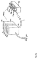
- the module according to FIG. 3a is designed in two parts.
- the first part M1 contains the actual daytime running light circuit and the cables of the corresponding supply voltages U B , Z, M are supplied either to the side or to the base of the module part M1.
- the end face of this part M1 has four plug contact devices E A1 , E A2 , E S1 , E S2 for the fuses S S1 , S S2 , S A1 , S A2 .
- this sub-module M1 has an approximately one on the side dovetail-shaped recess AU, whose counterpart on a Central electrical system is arranged.
- sub-module M1 With the aid of this recess AU, sub-module M1 becomes simple in the vehicle and mounted vibration-proof.
- the first module part M1 is connected to a second part of the module M2, which in each case contains two plug devices ST A1 , ST A2 , ST S1 , ST S2 for each lamp circuit. These plug-in devices are plugged into the corresponding fuse positions in the vehicle central electrical system.
- the module described offers an easy option for retrofitting of a motor vehicle with a daytime running light circuit.
- This module is installed in the central vehicle electrical system after Pull the fuses for parking lights and low beam into these slots. It is crucial that the fuse assignment to the daytime running light module is adjusted. The fuse can then be plugged back into the module to secure the lines.
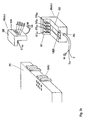
- a one-piece module is shown, which is L-shaped.
- the fuse slots E A1 , E A2 , E S1 , E S2 are provided on a side outer wall WA of the module M. But it is also conceivable that the fuse slots E A1 , E A2 , E S1 , E S2 are arranged on the front side SE of the module.
- the plug devices ST A1 , ST A2 , ST S1 , ST S2 are provided on one leg of the L-shaped module for insertion into the securing positions of the central electrical system ZE.
- the dovetail-shaped recess AU is arranged on the inside IS2 of the other leg of the module.
- the counterpart GAU of this recess is arranged directly on the central electrical system ZE, so that the module can be mounted directly on it.
- the dovetails are made during the injection molding of the plastic part, of which the module consists.
- the swallowtails are pushed onto the counterpart GAU.
- the module can also be used Latches VER can be secured against unintentional loosening.
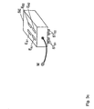
- a compact module that has only one connecting cable for the ground M has, which is advantageously screwed to the body of the vehicle can be shown in Fig. 3c.
- the supply with ignition and the fuse slots E A1 , E A2 , E S1 , E S2 are again provided on the front side SE of the module.
- the plug devices ST A1 , ST A2 , ST S1 , ST S2 are arranged on the opposite side of the module.
- the designations on the fuse positions indicate the terminals of the Feeders.
- the supply of the circuit can be by providing two bridges. Because ground potential is usually not available on fuse carriers the connection via a line.
Landscapes
- Engineering & Computer Science (AREA)
- Mechanical Engineering (AREA)
- Lighting Device Outwards From Vehicle And Optical Signal (AREA)
Description
- Fig. 1:
- Prinzip der erfindungsgemäßen Tagfahrlichtschaltung
- Fig. 2:
- die elektrische Anordnung der Tagfahrlichtschaltung im Kraftfahrzeug
- Fig. 3a-c:
- mögliche Varianten der Gestaltung des erfindungsgemäßen Moduls
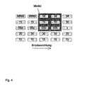
- Fig. 4:
- Anordnung der Sicherungssteckplätze an der Zentralelektrik
- Klemme 30:
- Sicherung von der Betriebsspannung UB versorgt,
- Klemme 58:
- Standlichtleitung vom Lenkstockschalter oder separater Einheit,
- Klemme 56b:
- Abblendlicht vom Lenkstockschalter oder separater Einheit,
- Klemme 56a:
- Fernlicht vom Lenkstockschalter oder separater Einheit,
- Kleimme 15:
- Zündspannung, geschaltete Klemme 30
Claims (13)
- Modul zur Aufnahme einer Tagfahrlichtschaltung, wobei elektrische Verbindungen zur Betriebsspannung (UB), Zündschaltung (Z) und Masse (M) vorhanden sind, dadurch gekennzeichnet, daß es mindestens eine Steckkontakteinrichtung (STA1, STA2, STS1, STS2) zum Einstecken in einen Sicherungsplatz einer Sicherung (SA1, SA2, SS1, SS2) eines Leuchten schaltkreises) einer Kraftfahrzeugzentralelektrik (ZE) und mindestens einen Steckplatz (EA1, EA2, ES1, ES2) zur Aufnahme der Sicherung aufweist, und die Sicherung die elektrische Kontaktierung der Tagfahrlichtschaltung zu dem Leuchtenschaltkreis realisiert.
- Modul nach Anspruch 1, dadurch gekennzeichnet, daß je eine Steckkontakteinrichtung zur Verbindung mit der fest in der Zentralelektrik verdrahteten Betriebsspannung und Zündschaltung vorgesehen ist.
- Modul nach Anspruch 1, dadurch gekennzeichnet, daß die Betriebsspannung (UB) und die Zündschaltung (Z) durch elektrische Kabel zugeführt werden.
- Modul nach Anspruch 2 oder 3, dadurch gekennzeichnet, daß die elektrische Verbindung an Masse (M) über ein Kabel erfolgt.
- Modul nach einem der Ansprüche 1, 2 oder 3, dadurch gekennzeichnet, daß es zweiteilig (M1, M2) gestaltet ist, wobei das erste Teil (M2) die Steckkontakteinrichtungen zum Einstecken in den Sicherungsplatz der Zentralelektrik (Z) trägt, während der mit dem ersten Teil (M2) über ein weiteres Kabel verbundene zweite Teil (M1) den Steckplatz zur Aufnahme der Sicherung aufweist.
- Modul nach einem der Ansprüche 1, 2 oder 3, dadurch gekennzeichnet, daß es annähernd schwalbenschwanzförmige Ausnehmungen (AU, GAU) aufweist, mittels welcher eine Befestigung an der Zentralelektrik (E) erfolgt.
- Modul nach einem der vorhergehenden Ansprüche 1 bis 6, dadurch gekennzeichnet, daß es ein Kunststoffspritzteil ist.
- Tagfahrlichtschaltung für ein in einem Kraftfahrzeug angeordnetes Modul nach Anspruch 1, bei welcher mit Einschaltung der Zündung (Z) die Leuchten des Standlichtes (LSHL, LSVL, LSVR, LSHR) und/oder des Abblendlichtes (LAL, LAR), mit Betriebsspannung verbunden sind, dadurch gekennzeichnet, daß die Zündung (Z) des Kraftfahrzeuges ein Schließer-Relais (Re1) ansteuert, welches zwischen Betriebsspannung (UB) und den Leuchten (LS) des Standlichtes angeordnet ist, wobei in Reihe zum Schließer-Relais (Re1) ein Öffner-Relais (Re2) angeordnet ist, über welches die Leuchten des Abblendlichtes (LA) von einem Lichtwahlschalter (LSK) schaltbar sind und jeweils ein Spulenanschluß der beiden Relais (RE1, RE2) an Masse liegt.
- Tagfahrlichtschaltung nach Anspruch 7, dadurch gekennzeichnet, daß parallel zu den Leuchten des Standlichtes (LS) die Begrenzungs-, Schluß-, Kennzeichen und/oder Instrumentenleuchten des Kraftfahrzeuges angeschlossen sind, welche über das Schließer-Relais (Re1) mit der Betriebsspannung (UB) verbindbar sind.
- Tagfahrlichtschaltung Anspruch 7 oder 8, dadurch gekennzeichnet, daß der Lichtwahlschalter (LSK) über eine erste Diode (D1) mit der Zündung (Z) verbunden ist.
- Tagfahrlichtschaltung nach Anspruch 9, dadurch gekennzeichnet, daß der Lichtwahlschalter (LSK) ein Lenkstockschalter zum manuellen einund ausschalten des Stand-, Abblend- und Fernlichtes ist.
- Tagfahrlichtschaltung nach einem der vorhergehenden Ansprüche, dadurch gekennzeichnet, daß der Zündschalter (Z) über eine zweite Diode (D2) mit dem Schließer-Relais (RE1) und dem Öffner-Relais (RE2) verbunden ist.
- Tagfahrlichtschaltung nach einem der vorhergehenden Ansprüche, dadurch gekennzeichnet, daß in jedem Leuchtenkreis des Abblend- (LA) und des Standlichtes (LS) unmittelbar vor den Leuchten jeweils eine Sicherung (SS1, SS2; SA1, SA2) angeordnet ist.
Applications Claiming Priority (2)
| Application Number | Priority Date | Filing Date | Title |
|---|---|---|---|
| DE19630425A DE19630425A1 (de) | 1996-07-27 | 1996-07-27 | Modul zur Aufnahme einer Tagfahrlichtschaltung sowie eine Tagfahrlichtschaltung |
| DE19630425 | 1996-07-27 |
Publications (3)
| Publication Number | Publication Date |
|---|---|
| EP0820903A2 EP0820903A2 (de) | 1998-01-28 |
| EP0820903A3 EP0820903A3 (de) | 1999-04-07 |
| EP0820903B1 true EP0820903B1 (de) | 2003-05-14 |
Family
ID=7801077
Family Applications (1)
| Application Number | Title | Priority Date | Filing Date |
|---|---|---|---|
| EP97104495A Expired - Lifetime EP0820903B1 (de) | 1996-07-27 | 1997-03-17 | Modul zur Aufnahme einer Tagfahrlichtschaltung sowie eine Tagfahrlichtschaltung für ein derartiges Modul |
Country Status (2)
| Country | Link |
|---|---|
| EP (1) | EP0820903B1 (de) |
| DE (2) | DE19630425A1 (de) |
Families Citing this family (2)
| Publication number | Priority date | Publication date | Assignee | Title |
|---|---|---|---|---|
| DE20216505U1 (de) | 2002-10-22 | 2003-02-27 | Huber, Stephan, 71364 Winnenden | Nachrüstsatz für Tagesfahrlicht |
| DE102018211266A1 (de) | 2018-07-09 | 2020-01-09 | Magna Exteriors Gmbh | Fahrzeugbauteil mit Leuchteneinschub sowie Verfahren zur Montage |
Family Cites Families (3)
| Publication number | Priority date | Publication date | Assignee | Title |
|---|---|---|---|---|
| US5030884A (en) * | 1988-01-21 | 1991-07-09 | Navistar International Transportation Corp. | Automotive vehicle daytime running light circuit |
| US5081565A (en) * | 1990-11-08 | 1992-01-14 | Chrysler Corporation | Daytime running light system |
| DE4324690C1 (de) * | 1993-07-23 | 1995-03-09 | Daimler Benz Ag | Lichtschalteinrichtung für ein Kraftfahrzeug |
-
1996
- 1996-07-27 DE DE19630425A patent/DE19630425A1/de not_active Withdrawn
-
1997
- 1997-03-17 DE DE59710070T patent/DE59710070D1/de not_active Expired - Fee Related
- 1997-03-17 EP EP97104495A patent/EP0820903B1/de not_active Expired - Lifetime
Also Published As
| Publication number | Publication date |
|---|---|
| DE59710070D1 (de) | 2003-06-18 |
| EP0820903A3 (de) | 1999-04-07 |
| EP0820903A2 (de) | 1998-01-28 |
| DE19630425A1 (de) | 1998-01-29 |
Similar Documents
| Publication | Publication Date | Title |
|---|---|---|
| DE4116244C2 (de) | ||
| DE4405083C2 (de) | Meßinstrumentenmodul | |
| DE19521887C2 (de) | Cockpit für ein Kraftfahrzeug | |
| DE3903818A1 (de) | Verdrahtungsvorrichtung fuer kraftfahrzeuge | |
| DE69005597T2 (de) | Verbesserung für Multiplex-Steuergeräte für eine Anordnung elektrischer Elemente in einem Kraftfahrzeug. | |
| DE2940142A1 (de) | Vorrichtung zur ueberwachung einer anzahl von sicherungen | |
| DE2105213A1 (de) | Elektrische Stromversorgungsvor richtung | |
| DE69013221T2 (de) | Hilfsplatine am Armaturenbrett eines Kraftfahrzeugs. | |
| DE19604493A1 (de) | Einrichtung zur Steuerung der Blinkleuchten eines Fahrzeuges | |
| EP0950564B1 (de) | Elektronischer Blinkgeber | |
| DE4316612C2 (de) | Elektrische Baugruppe für ein Fahrzeug | |
| DE102006054074B4 (de) | Elektroanschlusskasten und Halterung | |
| EP0820903B1 (de) | Modul zur Aufnahme einer Tagfahrlichtschaltung sowie eine Tagfahrlichtschaltung für ein derartiges Modul | |
| DE69404545T2 (de) | Elektrische Baugruppe für die Multiplexsteuerung einer Beleuchtungs- oder Signaleinrichtung an Kraftfahrzeugen | |
| DE4409183A1 (de) | Meßinstrumentenmodul und dessen elektrische Verbindungsvorrichtung | |
| DE19724254A1 (de) | Zentralelektrik mit einer Elektrik- oder Elektronikeinheit, insbesondere für Kraftfahrzeuge | |
| DE3014490C2 (de) | Elektrischer Schalter mit Beleuchtungseinrichtung | |
| EP1083087A2 (de) | Steuereinrichtung für eine Lichteinheit von Fahrzeugen | |
| EP1620926A1 (de) | Kontaktierungsanordnung | |
| DE102005045765A1 (de) | Fahrzeugscheinwerfer | |
| DE19937682C2 (de) | Elektrische Schaltungsanordnung | |
| DE4030513A1 (de) | Blinklichtsignalanlage fuer kraftfahrzeuge | |
| EP0645943A1 (de) | Betriebsgerät für elektrische Lampen | |
| EP0945671B1 (de) | Lampenträger für eine Fahrzeugleuchte | |
| DE19544235A1 (de) | Zentralelektrik für Kraftfahrzeuge |
Legal Events
| Date | Code | Title | Description |
|---|---|---|---|
| PUAI | Public reference made under article 153(3) epc to a published international application that has entered the european phase |
Free format text: ORIGINAL CODE: 0009012 |
|
| AK | Designated contracting states |
Kind code of ref document: A2 Designated state(s): DE FI FR GB SE |
|
| PUAL | Search report despatched |
Free format text: ORIGINAL CODE: 0009013 |
|
| AK | Designated contracting states |
Kind code of ref document: A3 Designated state(s): DE FI FR GB SE |
|
| 17P | Request for examination filed |
Effective date: 19990323 |
|
| AKX | Designation fees paid |
Free format text: DE FI FR GB SE |
|
| RAP1 | Party data changed (applicant data changed or rights of an application transferred) |
Owner name: SIEMENS AKTIENGESELLSCHAFT |
|
| GRAH | Despatch of communication of intention to grant a patent |
Free format text: ORIGINAL CODE: EPIDOS IGRA |
|
| RTI1 | Title (correction) |
Free format text: MODULE FOR RETAINING A DAYTIME RUNNING LIGHT CIRCUIT AND A DAYTIME RUNNING LIGHT CIRCUIT FOR SUCH A MODULE |
|
| GRAH | Despatch of communication of intention to grant a patent |
Free format text: ORIGINAL CODE: EPIDOS IGRA |
|
| GRAA | (expected) grant |
Free format text: ORIGINAL CODE: 0009210 |
|
| AK | Designated contracting states |
Designated state(s): DE FI FR GB SE |
|
| REG | Reference to a national code |
Ref country code: GB Ref legal event code: FG4D Free format text: NOT ENGLISH |
|
| REF | Corresponds to: |
Ref document number: 59710070 Country of ref document: DE Date of ref document: 20030618 Kind code of ref document: P |
|
| REG | Reference to a national code |
Ref country code: SE Ref legal event code: TRGR |
|
| GBT | Gb: translation of ep patent filed (gb section 77(6)(a)/1977) | ||
| PGFP | Annual fee paid to national office [announced via postgrant information from national office to epo] |
Ref country code: FI Payment date: 20040205 Year of fee payment: 8 |
|
| ET | Fr: translation filed | ||
| PGFP | Annual fee paid to national office [announced via postgrant information from national office to epo] |
Ref country code: SE Payment date: 20040304 Year of fee payment: 8 Ref country code: GB Payment date: 20040304 Year of fee payment: 8 |
|
| PLBE | No opposition filed within time limit |
Free format text: ORIGINAL CODE: 0009261 |
|
| STAA | Information on the status of an ep patent application or granted ep patent |
Free format text: STATUS: NO OPPOSITION FILED WITHIN TIME LIMIT |
|
| PGFP | Annual fee paid to national office [announced via postgrant information from national office to epo] |
Ref country code: FR Payment date: 20040323 Year of fee payment: 8 |
|
| 26N | No opposition filed |
Effective date: 20040217 |
|
| PG25 | Lapsed in a contracting state [announced via postgrant information from national office to epo] |
Ref country code: DE Free format text: LAPSE BECAUSE OF NON-PAYMENT OF DUE FEES Effective date: 20041001 |
|
| PG25 | Lapsed in a contracting state [announced via postgrant information from national office to epo] |
Ref country code: GB Free format text: LAPSE BECAUSE OF NON-PAYMENT OF DUE FEES Effective date: 20050317 Ref country code: FI Free format text: LAPSE BECAUSE OF NON-PAYMENT OF DUE FEES Effective date: 20050317 |
|
| PG25 | Lapsed in a contracting state [announced via postgrant information from national office to epo] |
Ref country code: SE Free format text: LAPSE BECAUSE OF NON-PAYMENT OF DUE FEES Effective date: 20050318 |
|
| EUG | Se: european patent has lapsed | ||
| GBPC | Gb: european patent ceased through non-payment of renewal fee |
Effective date: 20050317 |
|
| PG25 | Lapsed in a contracting state [announced via postgrant information from national office to epo] |
Ref country code: FR Free format text: LAPSE BECAUSE OF NON-PAYMENT OF DUE FEES Effective date: 20051130 |
|
| REG | Reference to a national code |
Ref country code: FR Ref legal event code: ST Effective date: 20051130 |