EP0820653B1 - Traktionsbatterieladesystem mit induktiver ankopplung - Google Patents
Traktionsbatterieladesystem mit induktiver ankopplung Download PDFInfo
- Publication number
- EP0820653B1 EP0820653B1 EP96907227A EP96907227A EP0820653B1 EP 0820653 B1 EP0820653 B1 EP 0820653B1 EP 96907227 A EP96907227 A EP 96907227A EP 96907227 A EP96907227 A EP 96907227A EP 0820653 B1 EP0820653 B1 EP 0820653B1
- Authority
- EP
- European Patent Office
- Prior art keywords
- charging
- battery
- vehicle
- energy
- current
- Prior art date
- Legal status (The legal status is an assumption and is not a legal conclusion. Google has not performed a legal analysis and makes no representation as to the accuracy of the status listed.)
- Expired - Lifetime
Links
Images


Classifications
-
- B—PERFORMING OPERATIONS; TRANSPORTING
- B60—VEHICLES IN GENERAL
- B60L—PROPULSION OF ELECTRICALLY-PROPELLED VEHICLES; SUPPLYING ELECTRIC POWER FOR AUXILIARY EQUIPMENT OF ELECTRICALLY-PROPELLED VEHICLES; ELECTRODYNAMIC BRAKE SYSTEMS FOR VEHICLES IN GENERAL; MAGNETIC SUSPENSION OR LEVITATION FOR VEHICLES; MONITORING OPERATING VARIABLES OF ELECTRICALLY-PROPELLED VEHICLES; ELECTRIC SAFETY DEVICES FOR ELECTRICALLY-PROPELLED VEHICLES
- B60L53/00—Methods of charging batteries, specially adapted for electric vehicles; Charging stations or on-board charging equipment therefor; Exchange of energy storage elements in electric vehicles
- B60L53/10—Methods of charging batteries, specially adapted for electric vehicles; Charging stations or on-board charging equipment therefor; Exchange of energy storage elements in electric vehicles characterised by the energy transfer between the charging station and the vehicle
- B60L53/14—Conductive energy transfer
-
- B—PERFORMING OPERATIONS; TRANSPORTING
- B60—VEHICLES IN GENERAL
- B60L—PROPULSION OF ELECTRICALLY-PROPELLED VEHICLES; SUPPLYING ELECTRIC POWER FOR AUXILIARY EQUIPMENT OF ELECTRICALLY-PROPELLED VEHICLES; ELECTRODYNAMIC BRAKE SYSTEMS FOR VEHICLES IN GENERAL; MAGNETIC SUSPENSION OR LEVITATION FOR VEHICLES; MONITORING OPERATING VARIABLES OF ELECTRICALLY-PROPELLED VEHICLES; ELECTRIC SAFETY DEVICES FOR ELECTRICALLY-PROPELLED VEHICLES
- B60L53/00—Methods of charging batteries, specially adapted for electric vehicles; Charging stations or on-board charging equipment therefor; Exchange of energy storage elements in electric vehicles
- B60L53/10—Methods of charging batteries, specially adapted for electric vehicles; Charging stations or on-board charging equipment therefor; Exchange of energy storage elements in electric vehicles characterised by the energy transfer between the charging station and the vehicle
- B60L53/11—DC charging controlled by the charging station, e.g. mode 4
-
- B—PERFORMING OPERATIONS; TRANSPORTING
- B60—VEHICLES IN GENERAL
- B60L—PROPULSION OF ELECTRICALLY-PROPELLED VEHICLES; SUPPLYING ELECTRIC POWER FOR AUXILIARY EQUIPMENT OF ELECTRICALLY-PROPELLED VEHICLES; ELECTRODYNAMIC BRAKE SYSTEMS FOR VEHICLES IN GENERAL; MAGNETIC SUSPENSION OR LEVITATION FOR VEHICLES; MONITORING OPERATING VARIABLES OF ELECTRICALLY-PROPELLED VEHICLES; ELECTRIC SAFETY DEVICES FOR ELECTRICALLY-PROPELLED VEHICLES
- B60L53/00—Methods of charging batteries, specially adapted for electric vehicles; Charging stations or on-board charging equipment therefor; Exchange of energy storage elements in electric vehicles
- B60L53/10—Methods of charging batteries, specially adapted for electric vehicles; Charging stations or on-board charging equipment therefor; Exchange of energy storage elements in electric vehicles characterised by the energy transfer between the charging station and the vehicle
- B60L53/12—Inductive energy transfer
-
- B—PERFORMING OPERATIONS; TRANSPORTING
- B60—VEHICLES IN GENERAL
- B60L—PROPULSION OF ELECTRICALLY-PROPELLED VEHICLES; SUPPLYING ELECTRIC POWER FOR AUXILIARY EQUIPMENT OF ELECTRICALLY-PROPELLED VEHICLES; ELECTRODYNAMIC BRAKE SYSTEMS FOR VEHICLES IN GENERAL; MAGNETIC SUSPENSION OR LEVITATION FOR VEHICLES; MONITORING OPERATING VARIABLES OF ELECTRICALLY-PROPELLED VEHICLES; ELECTRIC SAFETY DEVICES FOR ELECTRICALLY-PROPELLED VEHICLES
- B60L53/00—Methods of charging batteries, specially adapted for electric vehicles; Charging stations or on-board charging equipment therefor; Exchange of energy storage elements in electric vehicles
- B60L53/30—Constructional details of charging stations
- B60L53/31—Charging columns specially adapted for electric vehicles
-
- B—PERFORMING OPERATIONS; TRANSPORTING
- B60—VEHICLES IN GENERAL
- B60L—PROPULSION OF ELECTRICALLY-PROPELLED VEHICLES; SUPPLYING ELECTRIC POWER FOR AUXILIARY EQUIPMENT OF ELECTRICALLY-PROPELLED VEHICLES; ELECTRODYNAMIC BRAKE SYSTEMS FOR VEHICLES IN GENERAL; MAGNETIC SUSPENSION OR LEVITATION FOR VEHICLES; MONITORING OPERATING VARIABLES OF ELECTRICALLY-PROPELLED VEHICLES; ELECTRIC SAFETY DEVICES FOR ELECTRICALLY-PROPELLED VEHICLES
- B60L53/00—Methods of charging batteries, specially adapted for electric vehicles; Charging stations or on-board charging equipment therefor; Exchange of energy storage elements in electric vehicles
- B60L53/50—Charging stations characterised by energy-storage or power-generation means
- B60L53/56—Mechanical storage means, e.g. fly wheels
-
- B—PERFORMING OPERATIONS; TRANSPORTING
- B60—VEHICLES IN GENERAL
- B60L—PROPULSION OF ELECTRICALLY-PROPELLED VEHICLES; SUPPLYING ELECTRIC POWER FOR AUXILIARY EQUIPMENT OF ELECTRICALLY-PROPELLED VEHICLES; ELECTRODYNAMIC BRAKE SYSTEMS FOR VEHICLES IN GENERAL; MAGNETIC SUSPENSION OR LEVITATION FOR VEHICLES; MONITORING OPERATING VARIABLES OF ELECTRICALLY-PROPELLED VEHICLES; ELECTRIC SAFETY DEVICES FOR ELECTRICALLY-PROPELLED VEHICLES
- B60L53/00—Methods of charging batteries, specially adapted for electric vehicles; Charging stations or on-board charging equipment therefor; Exchange of energy storage elements in electric vehicles
- B60L53/60—Monitoring or controlling charging stations
- B60L53/67—Controlling two or more charging stations
-
- B—PERFORMING OPERATIONS; TRANSPORTING
- B60—VEHICLES IN GENERAL
- B60L—PROPULSION OF ELECTRICALLY-PROPELLED VEHICLES; SUPPLYING ELECTRIC POWER FOR AUXILIARY EQUIPMENT OF ELECTRICALLY-PROPELLED VEHICLES; ELECTRODYNAMIC BRAKE SYSTEMS FOR VEHICLES IN GENERAL; MAGNETIC SUSPENSION OR LEVITATION FOR VEHICLES; MONITORING OPERATING VARIABLES OF ELECTRICALLY-PROPELLED VEHICLES; ELECTRIC SAFETY DEVICES FOR ELECTRICALLY-PROPELLED VEHICLES
- B60L55/00—Arrangements for supplying energy stored within a vehicle to a power network, i.e. vehicle-to-grid [V2G] arrangements
-
- H—ELECTRICITY
- H02—GENERATION; CONVERSION OR DISTRIBUTION OF ELECTRIC POWER
- H02J—CIRCUIT ARRANGEMENTS OR SYSTEMS FOR SUPPLYING OR DISTRIBUTING ELECTRIC POWER; SYSTEMS FOR STORING ELECTRIC ENERGY
- H02J50/00—Circuit arrangements or systems for wireless supply or distribution of electric power
- H02J50/10—Circuit arrangements or systems for wireless supply or distribution of electric power using inductive coupling
-
- H—ELECTRICITY
- H02—GENERATION; CONVERSION OR DISTRIBUTION OF ELECTRIC POWER
- H02J—CIRCUIT ARRANGEMENTS OR SYSTEMS FOR SUPPLYING OR DISTRIBUTING ELECTRIC POWER; SYSTEMS FOR STORING ELECTRIC ENERGY
- H02J50/00—Circuit arrangements or systems for wireless supply or distribution of electric power
- H02J50/80—Circuit arrangements or systems for wireless supply or distribution of electric power involving the exchange of data, concerning supply or distribution of electric power, between transmitting devices and receiving devices
-
- H—ELECTRICITY
- H02—GENERATION; CONVERSION OR DISTRIBUTION OF ELECTRIC POWER
- H02J—CIRCUIT ARRANGEMENTS OR SYSTEMS FOR SUPPLYING OR DISTRIBUTING ELECTRIC POWER; SYSTEMS FOR STORING ELECTRIC ENERGY
- H02J7/00—Circuit arrangements for charging or depolarising batteries or for supplying loads from batteries
- H02J7/0013—Circuit arrangements for charging or depolarising batteries or for supplying loads from batteries acting upon several batteries simultaneously or sequentially
-
- B—PERFORMING OPERATIONS; TRANSPORTING
- B60—VEHICLES IN GENERAL
- B60L—PROPULSION OF ELECTRICALLY-PROPELLED VEHICLES; SUPPLYING ELECTRIC POWER FOR AUXILIARY EQUIPMENT OF ELECTRICALLY-PROPELLED VEHICLES; ELECTRODYNAMIC BRAKE SYSTEMS FOR VEHICLES IN GENERAL; MAGNETIC SUSPENSION OR LEVITATION FOR VEHICLES; MONITORING OPERATING VARIABLES OF ELECTRICALLY-PROPELLED VEHICLES; ELECTRIC SAFETY DEVICES FOR ELECTRICALLY-PROPELLED VEHICLES
- B60L2200/00—Type of vehicles
- B60L2200/22—Microcars, e.g. golf cars
-
- B—PERFORMING OPERATIONS; TRANSPORTING
- B60—VEHICLES IN GENERAL
- B60L—PROPULSION OF ELECTRICALLY-PROPELLED VEHICLES; SUPPLYING ELECTRIC POWER FOR AUXILIARY EQUIPMENT OF ELECTRICALLY-PROPELLED VEHICLES; ELECTRODYNAMIC BRAKE SYSTEMS FOR VEHICLES IN GENERAL; MAGNETIC SUSPENSION OR LEVITATION FOR VEHICLES; MONITORING OPERATING VARIABLES OF ELECTRICALLY-PROPELLED VEHICLES; ELECTRIC SAFETY DEVICES FOR ELECTRICALLY-PROPELLED VEHICLES
- B60L2270/00—Problem solutions or means not otherwise provided for
- B60L2270/30—Preventing theft during charging
- B60L2270/32—Preventing theft during charging of electricity
-
- H—ELECTRICITY
- H02—GENERATION; CONVERSION OR DISTRIBUTION OF ELECTRIC POWER
- H02J—CIRCUIT ARRANGEMENTS OR SYSTEMS FOR SUPPLYING OR DISTRIBUTING ELECTRIC POWER; SYSTEMS FOR STORING ELECTRIC ENERGY
- H02J2310/00—The network for supplying or distributing electric power characterised by its spatial reach or by the load
- H02J2310/40—The network being an on-board power network, i.e. within a vehicle
- H02J2310/48—The network being an on-board power network, i.e. within a vehicle for electric vehicles [EV] or hybrid vehicles [HEV]
-
- Y—GENERAL TAGGING OF NEW TECHNOLOGICAL DEVELOPMENTS; GENERAL TAGGING OF CROSS-SECTIONAL TECHNOLOGIES SPANNING OVER SEVERAL SECTIONS OF THE IPC; TECHNICAL SUBJECTS COVERED BY FORMER USPC CROSS-REFERENCE ART COLLECTIONS [XRACs] AND DIGESTS
- Y02—TECHNOLOGIES OR APPLICATIONS FOR MITIGATION OR ADAPTATION AGAINST CLIMATE CHANGE
- Y02E—REDUCTION OF GREENHOUSE GAS [GHG] EMISSIONS, RELATED TO ENERGY GENERATION, TRANSMISSION OR DISTRIBUTION
- Y02E60/00—Enabling technologies; Technologies with a potential or indirect contribution to GHG emissions mitigation
-
- Y—GENERAL TAGGING OF NEW TECHNOLOGICAL DEVELOPMENTS; GENERAL TAGGING OF CROSS-SECTIONAL TECHNOLOGIES SPANNING OVER SEVERAL SECTIONS OF THE IPC; TECHNICAL SUBJECTS COVERED BY FORMER USPC CROSS-REFERENCE ART COLLECTIONS [XRACs] AND DIGESTS
- Y02—TECHNOLOGIES OR APPLICATIONS FOR MITIGATION OR ADAPTATION AGAINST CLIMATE CHANGE
- Y02T—CLIMATE CHANGE MITIGATION TECHNOLOGIES RELATED TO TRANSPORTATION
- Y02T10/00—Road transport of goods or passengers
- Y02T10/60—Other road transportation technologies with climate change mitigation effect
- Y02T10/70—Energy storage systems for electromobility, e.g. batteries
-
- Y—GENERAL TAGGING OF NEW TECHNOLOGICAL DEVELOPMENTS; GENERAL TAGGING OF CROSS-SECTIONAL TECHNOLOGIES SPANNING OVER SEVERAL SECTIONS OF THE IPC; TECHNICAL SUBJECTS COVERED BY FORMER USPC CROSS-REFERENCE ART COLLECTIONS [XRACs] AND DIGESTS
- Y02—TECHNOLOGIES OR APPLICATIONS FOR MITIGATION OR ADAPTATION AGAINST CLIMATE CHANGE
- Y02T—CLIMATE CHANGE MITIGATION TECHNOLOGIES RELATED TO TRANSPORTATION
- Y02T10/00—Road transport of goods or passengers
- Y02T10/60—Other road transportation technologies with climate change mitigation effect
- Y02T10/7072—Electromobility specific charging systems or methods for batteries, ultracapacitors, supercapacitors or double-layer capacitors
-
- Y—GENERAL TAGGING OF NEW TECHNOLOGICAL DEVELOPMENTS; GENERAL TAGGING OF CROSS-SECTIONAL TECHNOLOGIES SPANNING OVER SEVERAL SECTIONS OF THE IPC; TECHNICAL SUBJECTS COVERED BY FORMER USPC CROSS-REFERENCE ART COLLECTIONS [XRACs] AND DIGESTS
- Y02—TECHNOLOGIES OR APPLICATIONS FOR MITIGATION OR ADAPTATION AGAINST CLIMATE CHANGE
- Y02T—CLIMATE CHANGE MITIGATION TECHNOLOGIES RELATED TO TRANSPORTATION
- Y02T90/00—Enabling technologies or technologies with a potential or indirect contribution to GHG emissions mitigation
- Y02T90/10—Technologies relating to charging of electric vehicles
- Y02T90/12—Electric charging stations
-
- Y—GENERAL TAGGING OF NEW TECHNOLOGICAL DEVELOPMENTS; GENERAL TAGGING OF CROSS-SECTIONAL TECHNOLOGIES SPANNING OVER SEVERAL SECTIONS OF THE IPC; TECHNICAL SUBJECTS COVERED BY FORMER USPC CROSS-REFERENCE ART COLLECTIONS [XRACs] AND DIGESTS
- Y02—TECHNOLOGIES OR APPLICATIONS FOR MITIGATION OR ADAPTATION AGAINST CLIMATE CHANGE
- Y02T—CLIMATE CHANGE MITIGATION TECHNOLOGIES RELATED TO TRANSPORTATION
- Y02T90/00—Enabling technologies or technologies with a potential or indirect contribution to GHG emissions mitigation
- Y02T90/10—Technologies relating to charging of electric vehicles
- Y02T90/14—Plug-in electric vehicles
-
- Y—GENERAL TAGGING OF NEW TECHNOLOGICAL DEVELOPMENTS; GENERAL TAGGING OF CROSS-SECTIONAL TECHNOLOGIES SPANNING OVER SEVERAL SECTIONS OF THE IPC; TECHNICAL SUBJECTS COVERED BY FORMER USPC CROSS-REFERENCE ART COLLECTIONS [XRACs] AND DIGESTS
- Y04—INFORMATION OR COMMUNICATION TECHNOLOGIES HAVING AN IMPACT ON OTHER TECHNOLOGY AREAS
- Y04S—SYSTEMS INTEGRATING TECHNOLOGIES RELATED TO POWER NETWORK OPERATION, COMMUNICATION OR INFORMATION TECHNOLOGIES FOR IMPROVING THE ELECTRICAL POWER GENERATION, TRANSMISSION, DISTRIBUTION, MANAGEMENT OR USAGE, i.e. SMART GRIDS
- Y04S10/00—Systems supporting electrical power generation, transmission or distribution
- Y04S10/12—Monitoring or controlling equipment for energy generation units, e.g. distributed energy generation [DER] or load-side generation
- Y04S10/126—Monitoring or controlling equipment for energy generation units, e.g. distributed energy generation [DER] or load-side generation the energy generation units being or involving electric vehicles [EV] or hybrid vehicles [HEV], i.e. power aggregation of EV or HEV, vehicle to grid arrangements [V2G]
Definitions
- the present invention relates to apparatus and methods for providing fast recharging of electric vehicle batteries.
- the present invention provides a charging station and a method for charging the battery of a vehicle whereby delivery of charging energy to the electric vehicle battery may be accomplished no matter what kind of charge controller may be on board the vehicle.
- the present invention provides a charging station and a method whereby charging energy is transferred from the charging station to the electric vehicle as alternating current in the range of from 10 kHz up to 200 kHz, and then rectified in the vehicle. Control of the rate of delivery of charging energy may depend on various criteria depending on the nature and sophistication of a battery charging control module which may be present in the vehicle, or otherwise under the control of a charge control module which is present in the charging station.
- Electric vehicles are now becoming more popular for a variety of reasons. Indeed, electric vehicles may become mandated to a greater or lesser extent due to the imposition of regulations requiring that at least a certain percentage of vehicles sold by any one manufacturer of vehicles - especially, passenger cars with seating from two to nine passengers, including the driver - and which are conventionally powered by internal combustion engines, must also include a specific number of vehicles that are so-called "zero emission” vehicles. That means that such vehicles have no emissions of noxious gasses, and the most common type of vehicle which would meet such stringent standards is an electric vehicle. Electric vehicles are powered by batteries, and present a number of problems or other difficulties to be overcome.
- the voltage and frequency conditions on the primary or charging station side of the inductive coupling interface may be set to be constant for all charging stations, no matter what may be the current acceptance characteristics and terminal voltage of the traction battery that is mounted in the vehicle.
- the voltage and current requirements for any specific traction battery in a vehicle are automatically accommodated by the specific design of the secondary side of the transformer which is mounted in the vehicle. Therefore, the vehicle or secondary side of the inductive coupler is thus battery and vehicle specific, for each vehicle and the traction battery mounted therein.
- the present invention demonstrates the awareness that there must be safe and efficient recharging in very short time periods; and, of course, in order for a charging station to deliver 20 to 50 kWh to an electric vehicle battery in 10 or 20 minutes, then the station must have high power ratings in the order of 100 to 300 kW.
- Such charging stations or battery chargers are not likely to be widely distributed so as to be found in everyone's garage.
- high power connections to the locally available power distribution grid are likely to be approved and located in more widely spaced distributions, perhaps not significantly different than the manner in which gasoline refuelling service stations are presently distributed, or even into strategic locations such as downtown public parking lots, and the like.
- the present invention will overcome such difficulties by providing a universal charging station which has the capability of charging a large variety of electric automobiles and electric vehicles over a wide range of parameters - including, especially, initial charging current and initial voltage conditions under which the charging operation will take place.
- the power connector by which an electric vehicle is connected to a charging station must, therefore, have at least two wires that are capable of carrying the maximum value of charging current to be delivered, at the delivery voltage.
- any battery to be charged must be capable of accepting an initial charging current at a rate greater than 1C - that is, at a rate in amperes that is greater than the capacity in ampere-hours of the battery.
- BEMS Battery Energy Management System
- the present invention provides for a universal charging station which is capable of charging a great variety of electric vehicles, whether or not they have on board a sophisticated Battery Energy Management System controller, or other controllers, or even if they have no on board controller at all. Accordingly, a universal station in keeping with the present invention will, itself, be equipped with a power section - whose sole function is to deliver charging energy to the battery - and a charge control module whose purposes are described hereafter.
- the modes in which the universal charging station of the present invention may operate are, in descending order of their sophistication, as follows:
- the charging station may function as a controlled current source under the control of a battery specific charging control module that is on board the electric vehicle.
- the controller section of the charging station acts as a slave to the on board battery specific charging control module in the electric vehicle, in a classical master-slave configuration.
- the charging station of the present invention may function substantially in keeping with MINIT-CHARGER technology, whereby the parameter of maximum initial charging current may be more or less automatically established by polling the electric vehicle to determine if there is on board a module which at least identifies the maximum charging current to which the battery should be initially subjected.
- the universal charging station of the present invention may operate in a mode by which the parameter of maximum initial charging current has been entered either manually or through a data interface by insertion of a card on which such data may be encoded.
- maximum initial charging current, or control of the charging current are predicated on the characteristics of the transformer - and especially the secondary side thereof, since the primary side of the transformer is consistent at all charging stations - whereby direct current charging energy that is delivered to the traction battery being charged is generally a high current, low voltage energy; notwithstanding that low current, high voltage energy has been delivered to the primary side of the inductive coupled transformer.
- the secondary side of the inductive coupled transformer is arranged to deliver nominal charging voltage in the range of 72 to 324 volts, as determined by the specifications of the battery to be charged.
- the primary side voltage will be in the range of 800 volts, but industry standards may eventually be settled in the range of less than 600 volts and perhaps as much as 1,200 volts, or more. In any event, current control is effected by controlling the value of current on the delivery or primary side.
- the on board battery specific charging control module which is present in the electric vehicle makes the decisions, and sends signals to the charging station as to the magnitude and the timing of the charging current.
- control of the charging function is exercised by the charge control module located in the charging station.
- charging stations in keeping with the guidelines established hereby, will offer enhanced "user friendliness" through its features.
- Those features may, for example, include a credit or debit card interface, whereby a retail customer may simply and easily pay for the energy delivered to his elcctric vehicle battery.
- the charging station may include registers whereby the initial charging current may be manually entered; or it may include a data interface whereby a card that is encoded with the charging parameters settings required for the specific battery carried in the electric vehicle may be inserted into the data interlace to ensure that no mistakes or operator errors occur.
- That card may have the nominal charging voltage and maximum charging current data encoded into it such as by any of a magnetic stripe, or by such means as a memory chip, or by punched holes, or by embossed depressions and/or mounds, with the assumption that the data interface is compatible with any such card.
- a charging station of the present invention might well be equipped with a meter which might define in advance the amount of energy to be delivered to the battery, or the monetary price of the energy to be delivered to the battery, together with appropriate shut off means to terminate the delivery of charging current when a predetermined amount of energy has been delivered or a predetermined monetary price of the energy has been delivered, whichever occurs first.
- the unit monetary price of the energy could be varied by controllers within the charging station, whereby the unit price for energy to be delivered from it may be dependent upon the time of day - it generally being understood that delivery of charging energy during ordinary daytime hours when demand for delivery of electrical energy from the local power authority is quite high, would mean that the unit price for the energy might be higher than in the evening when many offices, stores, and factories, etc., have shut down for the day.
- the local power authority may require a utility interface to be placed in the charging station, whereby it may communicate therewith over its own power lines to set and reset the unit valley price.
- load management and other functions such as facilities to bill the cost for charging energy delivered to an electric vehicle to the vehicle operator's office, interlock provisions to prevent theft of,charging energy except with appropriate authorization to operate the charging station, and so on.
- the concept of the charging station is extended to a service station, there may be a number of similar charging stations or "charge dispensers" that are physically separated one from the other so that a plurality of electric vehicles can be accommodated.
- a plurality of electric vehicles might be placed before a plurality of charging stations, all of which are conveniently connected to and fed by a single station rectifier.
- the multiple charging stations may be operated sequentially so as to charge one electric vehicle at a time, or several may be operated simultaneously provided that the amount of charging energy delivered at any one time does not exceed a predetermined maximum.
- priorities or other function controls may be imposed to ensure efficient utilization of the multiple charging stations connected to a common rectifier source.
- local energy storage devices such as a flywheel unit or stand-by batteries might be provided for load levelling and so as to limit the peak power being drawn from the distribution power grid supplied by the local power authority.
- the operating functions of charging stations generally in keeping with the present invention will depend, at least in part, on the ability of the power section in the charging stations to turn on and turn off very quickly.
- a monitoring system which monitors the data communication link between the electric battery being charged and the power station, and the charge control modules may be established in such a manner that they continuously monitor and exchange signals periodically - say, every 0.5 to 2 seconds. The monitoring system would determine if there has been no communication of data over the communication link for a predetermined period of time - say, 4 to 6 seconds - and if so, signals would be initiated to shut down the charging operation so as to avoid serious implications of overcharge to the battery.
- the charging station be equipped with an appropriately designed and dimensioned switching inverter module which is arranged to delivery energy at the selected primary voltage, and at the selected frequency.
- Each vehicle would, in turn, be equipped with the appropriately designed and dimensioned inductive coupler and a rectifier so as to deliver charging energy at the voltage level and charging current rates as are determined to be appropriate for the respective traction battery mounted in the vehicle.
- NOR United States patent No. 5,202,617, issued April 13, 1993 teaches a fundamental charging station for electric vehicles.
- the electric vehicle battery may be charged either under control of a on board controller, or the charging operation may be manually controlled.
- the patent requires a power connector and associated power cable for connecting to the vehicle, an interface with signal cables to carry status and/or control signals between the vehicle and the power controller within the charging station, and a lockout which precludes delivery of power to the vehicle except when the power connector is in place.
- the operation of the charging station is battery specific, and thus the operating parameters of the charging station may vary from one electric vehicle to another.
- NOR et al were issued United States patent No. 5,204,611 on April 20, 1993, for a more advanced battery charger.
- the resistance free terminal voltage of the battery is detected during an interval when the charging current is interrupted and compared against an independent reference voltage; but the reference voltage may be altered at any instant in time as a function of the ambient temperature, or the internal temperature or pressure of the battery, or as a function of the charging current when it is within a predetermined range, or even if a particular change in the value of charging current occurs over a predetermined period of time.
- These various provisions preclude, for example, thermal runaway, and they assure very rapid and complete charging operations for the battery no matter what its condition may have been when it was first connected to the battery charger, provided that it is capable of accepting charge in the first instance.
- NOR et al United States patent No. 5,548,200 teaches a universal charging station and method for charging electric vehicle batteries. That application teaches a method and apparatus which delivers direct current charging energy to one or a plurality of vehicles, depending upon operating conditions, where the initial level of charging current and the initial charging voltage are set and determined in keeping with parameters dictated either by an on board battery charging controller, or a charge controller in the charging station, or by manual or automatic setting of those parameters. However, as noted, that charging station is strictly a direct current operating device.
- a feedback circuit which compares the voltage across the output terminals with a reference voltage and thereby controls the frequency of the AC voltage so as to maintain the voltage across the output terminals at a predetermined value.
- KLONTZ et al United States patent No. 5,157,319, issued October 20, 1992 provides a contactless battery charging system which includes a primary converter for converting power from a power source into a high frequency power.
- a secondary converter is on board an electric vehicle, and is coupled to the battery for converting the high frequency power into charging power supplied to the battery or energy storage device.
- That charging system operates in the range of from 2 kHz to 50 kHz, and may deliver significant quantities of electrical energy.
- the invention is, however, more particularly directed to the specific structure of the inductive coupling device. No thought is given as to the manner in which charging current control will be carried out.
- the inductive coupler is such that when the primary and secondary coils are mated, an,extremely low leakage inductance transformer is formed. That transformer permits electric power transfer without metal-to-metal contact, and thereby allows easy removal of the primary or secondary coil away from the transformer.
- the transformer is said to operate in a frequency domain of about 40 kHz with a power transfer of approximately 6,000 watts being transferred through an inductive coupler having a volume of about 25.8 cubic inches, thereby yielding a power density of 230 watts per cubic inch.
- the inductive coupler provides a weatherproof device to couple power to a load, such as an electric vehicle, so as to recharge its propulsion battery. No thought is given, however, as to the manner of control of the charging current.
- a further KLONTZ et al United States patent No. 5,341,083, issued August 23, 1994 shows a variety of alternative schemes for providing a contactless recharging system and method for transferring power from a primary convertor through cables and a co-axial winding transformer to a secondary convertor installed in an electric vehicle, and thence to the vehicle battery.
- the power transmitted from the primary convertor to the co-axial winding transformer is transferred at a high frequency of from 2 to 50 kHz.
- the patent is particularly directed to the provision of alternative low cost recharging stations having various degrees of control over the proper or correct recharge strategy for the vehicle battery.
- KLONTZ et al have also published a paper entitled An Actively Cooled 120 KW Co-Axial Winding Transformer For Fast Charging Electric Vehicles. published at pages 1049 through 1054 of IEEE publication No. 0-7803-1993-1/94.
- the purpose of this paper is to teach yet another transformer structure operating at 15 kHz to 200 kHz, and providing a highly efficient transformer having a power density in the range of 25 kW/kg.
- the structure is a co-axial winding transformer.
- both a method of charging the battery of an electric vehicle and an apparatus therefor where the battery is capable of accepting initial charging current at a rate in amperes which is greater than the capacity of the battery in ampere-hours, and where the charging station from which the charging energy is delivered to the battery is arranged to deliver charging energy at a predetermined voltage and at a delivery frequency which is typically in the range of from 10 kHz up to 200 kHz.
- the charging energy is transferred to the vehicle through an inductive coupler, having a primary side connected to the charging station and a secondary side mounted within the vehicle, and thence through a rectifier mounted in the vehicle to the traction battery.
- the method comprises the steps of:
- the method further comprises one of the steps of:
- step (e) signals to control the delivery of charging current from the charging station are delivered over the communication means.
- steps (f) and (g) the data which are indicative of the instantaneous terminal voltage of the battery, are transferred between the battery and the charging station over of the battery, are transferred between the battery and the charging station over the communication means.
- the secondary side of the inductive coupler may be mounted so as to present a receptacle having a selected size in the vehicle, into which the primary side of the inductive coupler may be inserted so as to form a separable core transformer.
- the separable core transformer has a high turns ratio, whereby the primary voltage is high and the primary current is low when compared with the charging voltage and current being delivered to the battery through the rectifier mounted in the vehicle.
- a typical logic flow diagram 20 for operation of a charging station in keeping with the present invention is provided.
- a determination is made at 24 as to whether there is a vehicle connected to the charging station. If yes, the vehicle is interrogated at 26 to determine if there is a Battery Energy Management System on board the vehicle. If no, the vehicle is interrogated at 28 to determine if there is any other compatible battery specific charging control module on board the vehicle; and if no, the vehicle is interrogated at 30 to determine if there is a "personality module" on board the vehicle whereby the personality module will at least identify the criteria of maximum charging current under which conditions the battery may be charged in the shortest possible time period.
- the decision is made at 32 as to whether the charging station will be manually operated. If no, the logic loops back to 24, where a determination is made if there is, indeed, a vehicle connected to the charging station. If manual operation is selected at 32, there must at least be present on board the vehicle a monitoring means which determines the terminal voltage of the battery being charged.
- step 26 or 28 determines that there is a battery specific charging control module on board the vehicle
- charging operation is started at 34.
- Operators 36 and 38 indicate that the on board battery specific charging control module operates the charging station as a controlled current source, with the on board controller making all of the decisions as to the value of charging current at any instant in time.
- start and stop commands that are issued repetitively, for example every second, which are part of the monitoring function to determine if the charging operation is proceeding normally, and if the established criteria for charging current at any instant in time are still being followed.
- a decision is made at 40 to stop the charging operation. If so, then the charging station interrogates at 42 to determine if the vehicle has been disconnected and if so, the charging operation is done as at 44.
- a start decision is made at 46.
- the maximum current reading is taken at 48, and control is passed to the charging station at 50.
- the charging station follows charging procedures and methods particularly as discussed in United States patent No. 5,202,617 and No. 5,204,611, mentioned above.
- stop commands are periodically issued, for example every second, and sooner or later the decision is made at 52 to stop the charging operation because the battery is fully charged.
- the charging station interrogates itself at 42 to determine if the vehicle has been disconnected, and if so the charging operation is done at 44.
- the charging station may be equipped with a meter which might define in advance the amount of energy to be delivered to the battery or the monetary price of the energy to be delivered to the battery, together with appropriate shut off means to terminate the delivery of charging current when a predetermined amount of energy has been delivered or a predetermined monetary price of energy has been delivered, whichever occurs first.
- a meter which might define in advance the amount of energy to be delivered to the battery or the monetary price of the energy to be delivered to the battery, together with appropriate shut off means to terminate the delivery of charging current when a predetermined amount of energy has been delivered or a predetermined monetary price of energy has been delivered, whichever occurs first.
- the maximum value of charging energy to be delivered to the battery is accomplished by selectively setting the meter.
- the unit monetary price of energy may be altered depending on the time of day when charging current flows to the battery.
- step 56 or 60 the charge control module in the charging station takes over at 62.
- a number of decision steps must be followed; the first of those is at 64 where a determination has been made as to whether or not preset values of total kWh to be delivered to the battery have been reached, or if a predetermined price of energy has been reached. If yes, then immediately the charging function is terminated, and the charging station interrogates itself at 42 to determine if the vehicle has been disconnected. If the preset price or amount of energy to be delivered to the battery has not yet been reached, a decision is made at 66 as to whether any particular plateau - which typically would he whether the shadery has achieved a specific terminal voltage - has been reached.
- steps 40, 52, and 68 are also indicative of manual intervention in each case, whereby a manual stop command is given.
- decisions to terminate the charging function may be made at 40, 52, 66, or 68, depending on the sophistication of the on board battery charging control module, or the charge control module in the charging station, and depending on the amount of data being communicated across the data communications line, whereby the charging function might be terminated in the event that the internal temperature of the battery, or its internal pressure, become too high, or in keeping with other criteria more particularly as described in United States patent No. 5,204,611, introduced above.
- a vehicle 80 is shown being attached to a charging station 82.
- the vehicle has a battery 84 on board, and may have a battery charging control module or Battery Energy Management System 86, or other monitoring device or module, as described above.
- the vehicle 80 is connected through the inductive coupler 88 to the charging station 82.
- a pair of wires or a co-axial 90 provided, which is capable of carrying the high voltage, high frequency charging energy to be delivered to the inductive coupler 88, through rectifier 85, and thence to the battery 84.
- a data communication means 92 that is provided, and it may be dedicated data wires, or it may be a power line carrier device, or optical fibre. Opto-couplers and associated data transfer means may be provided, or low power inductive couplers with their associated transfer means.
- the data communication line may be a radio frequency transmitter and receiver located appropriately in each of the vehicle 80 and the power station 82. Appropriate wire, cable, optical couplers, or fibre connectors or transfer means will be provided for the radio frequency transmitter and receiver, as necessary.
- the power station 82 is shown being connected to the grid connection at wires 94, which is the high voltage AC power lines provided by the local power authority, and from which electrical energy is drawn. Such arrangement is, however, at the power authority frequency, - usually 50 Hz or 60 Hz.
- the face of the power station may be provided with a manual interface and key pad 96, or a card slot 98 that communicates with a data interface within the power station 82. In either event, there are registers or microprocessors thereby provided and associated with the key pad 96 and the card slot 98 by which the setting of maximum charging current may be established manually, or by inserting a card into card slot 98.
- the card and the data interface associated with card slot 98 will be compatible and may be such as to read "personality data" such as the maximum charging current that may be encoded into the card by any of a magnetic stripe, punched holes, embossed depressions and embossed mounds.
- Other annunciators 100 and 102 may be provided to give a running indication of the amount of energy being delivered in kWh or its cost in local currency, such as dollars.
- the utility interface on the front face of the charging station 82 may be appropriate to equip the utility interface on the front face of the charging station 82 with appropriate programmable registers or the like within the charging station to set the price per unit of energy depending on the time day.
- the time dependent pricing provides benefit for all of the power authority, the operator of the charging station, and the consumer, since higher daytime prices might tend to discourage operation of the charging station during peak energy consumption times during the day. It may be that the price to the operator of the charging station from the local power authority may vary depending on the time of day. In any event, there may be less demand on the power authority and economies to be realized by the consumer, if the charging station is operated at off-peak hours.
- the Battery Energy Management System 86 which is on board the vehicle 80 may also have with it suitable monitoring means to monitor the battery 84 during charge and/or discharge, as taught in United States patent No. 5,206,578, introduced above.
- the personality module which might be provided on board the vehicle 80, in place of the charge controller 86, may be designed to provide a calibrated divider network whose purpose is to make the battery 84 appear to the charging station 82 as if it is a standard lead/acid battery of known nominal voltage. Of course, at the same time, maximum charging current is established by the personality module. Thus, various electrochemical systems for the battery 84 may be accommodated.
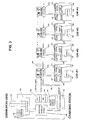
- a typical system is shown as might be operated by a fleet operator who owns a number of electric vehicles which might be delivery vehicles, fork lift trucks, golf carts, rental vehicles, or the like.
- a plurality of vehicle batteries may be charged from the single charging station 120, by distributing charging energy to any one of a plurality of switches or contactors 122, to which a plurality of electric vehicles 124 may be connected.
- Each vehicle 124 has its own on board battery 126, and its own on board charge controller, or battery charging control module 128, in the present discussion.
- each vehicle 124 will be equipped with its own inductive coupler 127, and its own rectifier 129.
- a communication coupler 131 is provided, whereby data which are unique to each vehicle 124 may be transferred to the charging station 120.
- the charging station 120 is connected to the distribution grid at 130, through rectifier 134.
- the utility interface 132 provides means for the local power authority to communicate with the charging authority to communicate with the charging station, for such purposes as to change the monetary unit price, as discussed above.
- Within the charging station 120 there is a charge control module 136, a switching inverter module 138, a user interface 140, and a vehicle interface 142.
- the user interface may be the same as key pad 96, for example, shown in Figure 2 and/or card slot 98.
- the vehicle interface 142 provides means by which a data communication link 144 communicates with the charging station 120 from each communication coupler 131.
- the charger output from the charging station is at 146, and a power line comprising a pair of wires or a co-axial cable 148 provides the charging current to each of the contactors 122.
- each of the contactors 122 has its own unique designation ⁇ for example, as indicated by the designations 122a, 122b, 122c, 122d, etc.
- means are provided to selectively close any one of the contactors while retaining the power line 148 in connection with all of the switches or contactors.
- the switching inverter module varies significantly from the switching inverter module which is discussed in Applicant's copending application No. 08/275,878, referenced above.
- the purpose of the switching inverter module is to provide current control so as to control the rate of delivery of charging energy.
- the switching inverter in the prior invention may be utilized so as to isolate the direct current power output from the charging station which receives its input power over the power lines from the distribution grid.
- more pure and controlled direct current power can be provided; and there is also thus provided galvanic isolation of any vehicle which may be connected to the power charging station from the distribution grid.
- the purpose of the switching inverter module is to provide high voltage alternating current in the frequency range of from 10 kHz up to 200 kHz. Conveniently, it has been found that a suitable operating frequency for most purposes is around 60 kHz. Thus, the output from the charger output 146 is high voltage, low current, high frequency charging energy.
- the decision as to the order of sequentially closing one at a time of the switches or contactors 122a, 122b, etc. may be established according to any one of a number of priority protocols. For example, it may well be that the operator or owner of the charging station and all of the vehicles connected to it might choose to establish no priority, and will close each of the switches or contactors 122a, 122b, etc., in sequence, accordingly to their respective unique designation. On the other hand, he may establish a priority as to which of the respective batteries 126 will be charged first by determining which of those batteries might require either the greatest amount of charging energy or the least amount of charging energy. The other batteries would then be ranked according to their respective charge requirements, either greater or lesser in keeping with the protocol being established. Alternatively, some other user-determined priority protocol may be established.
- FIG. 4 a typical public service station 180 is shown.
- a charging station or outlets 182 to each of which a vehicle 184 may be connected in much the same manner and using the same arrangements as shown in Figure 2.
- Each charging station 182 may have essentially the same appearance and operation as charging station 82, described above in association with Figure 2.
- each vehicle 184 is provided with its own inductive coupler receptacle 181 and rectifier 183, as described above with reference to Figures 2 and 3.
- Each of the charging stations 182 within service station 180 may have a power rating of 150 kW, for example.
- the single and common controlled rectifier 186 from which each of the charging stations 182 is supplied charging power may have a rating of 300 kW.
- the utility interface provides the appropriate connections to the distribution grid 192 which is provided by the local power authority; the billing interface 190 interfaces for purposes of accounting and management to each of the charging stations 182 and to such as a data network operated by credit card and debit card issuers.
- more than one vehicle 184 may be connected to more than one charging station 182 at any one time. If so, and if each of the associated electric vehicle batteries is absorbing maximum charging current at one time, the output from the controlled rectifier 186 may exceed its rating. In that case, a supervisory controller 185 may monitor the output of the controlled rectifier, and may be such as to issue signals which either reduce the output from each of the charging stations 182 that may be operating, or which might preclude the possibility of another of the charging stations 182 from coming on line until such time as the output from the controlled rectifier has reduced below the predetermined allowable maximum output.
- means may be provided for load levelling, whereby the energy demands by the controlled rectifier 186 from the distribution grid 192 may be reduced.
- a load levelling battery 196 may be provided, or a load levelling flywheel energy storage device 198 may be provided. Their function is to accumulate energy during off-peak hours, when the price of energy from the distribution grid is low, and to support the service station 180 whenever necessary during peak hours.
- the purpose of the charge/discharge controller 194 may also be to ensure that the load levelling battery 196 is recharged during off-peak hours to its maximum capacity.
- each inductive coupler by which charging energy may be transferred from the charging station to the vehicle comprises a primary side and a secondary side.
- Each of Figures 5(a) and 5(b) shows generally the physical and electrical arrangement by which the inductive coupled transformer, or inductive coupler, is established. As noted, the differences between the embodiments of Figure 5(a) and Figure 5(b) are the manner of rectification which is carried out in the vehicle.
- An inductive coupler is shown generally at 200, and it comprises a primary winding 210 and a secondary winding 212. It will be noted that there is a high turns ration between the primary and secondary windings 210 and 212.
- the primary side 211 and the secondary side 213 are physically arranged so that the ferrite member 214 and ferrite member 216 can be juxtaposed in such a manner as to establish magnetic flux, while at the same time the ferrite member 214 is contained within a socket or receptacle 218 defined by the ferrite member 216 and its housing.
- the physical assembly of the inductive coupler 200 is not unlike placing a plug into a receptacle.
- the physical design of the receptacle and of the plug can be standardized, and moreover that the primary side 211 of the inductive coupler can be designed so as to be consistent, having the same physical and electrical characteristics for all electrical charging stations.
- the electrical characteristics of the secondary side 213 can be specifically designed to accommodate the respective rectifier arrangement 217 or 219 and the associated battery 220 or 222, as shown in Figures 5(a) and 5(b). It may be that the charging voltage, and the current acceptance characteristic of battery 220 might be considerably different than that of battery 222; but it is obvious that even though the primary side of the inductive coupler has predetermined and settled physical and electrical characteristics, the secondary side can be arranged to provide the necessary DC voltage and DC current required to charge battery 220 or battery 222.
- the charging energy delivered by the charging station to the vehicle is at high frequency (in the order of 10 kHz up to 200 kHz), having high voltage and low current. This, in turn, is transformed and rectified to low voltage, high current power, in the vehicle.
Claims (18)
- Verfahren zum Aufladen einer Batterie (84, 26) für ein Elektrofahrzeug (80, 24), wobei die Batterie einen Anfangsladestrom mit einer Ampèrerate aufnehmen kann, die größer ist als die Ampère-Stundenkapazität der Batterie, und wobei eine Ladestation (82, 120, 182), von der aus die Ladeenergie der Batterie zugeführt wird, so angeordnet ist, daß sie Ladeenergie mit einer vorbestimmten Spannung und einer Zufuhrfrequenz zuführt, die im Bereich zwischen 10 kHz und maximal 200 kHz liegt, wobei die Ladeenergie dem genannten Fahrzeug durch einen induktiven Koppler (88, 200) zugeführt wird, der eine Primärseite (210) hat, die mit der genannten Ladestation verbunden ist, und eine Sekundärseite (212), die in dem genannten Fahrzeug montiert ist, und von dort durch einen in dem genannten Fahrzeug montierten Gleichrichter (217, 219) zu der genannten Batterie, wobei das genannte Verfahren durch die folgenden Schritte
gekennzeichnet ist:wobei das genannte Verfahren ferner die folgenden Schritte umfaßt:a) Ausstatten des genannten Fahrzeuges mit der genannten Sekundärseite des genannten induktiven Kopplers, so daß Ladeenergie zu dem genannten Fahrzeug und von dort durch den genannten Gleichrichter zu der genannten Batterie als Gleichstrom und mit einer Ladespannung zugeführt wird, die durch die Übertragungseigenschaften der genannten Sekundärseite des genannten induktiven Kopplers auf der Basis der genannten vorbestimmten Spannung und Zufuhrfrequenz von Ladeenergie bestimmt wird, die die genannte Ladestation der genannten Primärseite des genannten induktiven Kopplers zuführt, um die genannte Ladespannung für die genannte in Aufladung befindliche Batterie geeignet zu machen;b) physisches Positionieren der Primär- und der Sekundärseite des genannten induktiven Kopplers in eine räumliche Beziehung, um eine induktive Kopplung dazwischen herzustellen;c) Herstellen eines Kommunikationsmittels (92, 144), das Daten über den Ladezustand der in Aufladung befindlichen Batterie zwischen der Batterie und der Ladestation übertragen kann;d) Abfragen (26) des Fahrzeugs über das genannte Kommunikationsmittel, um zu ermitteln, ob ein batteriespezifisches Ladesteuermodul (86) vorhanden und mit der genannten Batterie in dem genannten Fahrzeug assoziiert ist; oder ob in dem genannten Fahrzeug ein Personality-Modul vorhanden ist (28), das wenigstens das Kriterium des maximalen Ladestroms identifiziert, mit dem die Batterie mit der genannten vorbestimmten Ladespannung in der kürzestmöglichen Zeit aufgeladen werden kann; oder um in Abwesenheit eines batteriespezifischen Lademoduls in Verbindung mit der genannten Batterie oder eines Personality-Moduls, das wenigstens das Kriterium des maximalen Ladestroms identifiziert, mit dem die Batterie mit der genannten vorbestimmten Ladespannung in der kürzestmöglichen Zeit geladen werden kann, zu ermitteln, ob in dem genannten Fahrzeug wenigstens ein Überwachungsmittel vorhanden ist, um den Wert der Klemmenspannung der in Aufladung befindlichen Batterie zu messen;wobei in Schritt (e) Signale zum Regeln der Zufuhr von Ladestrom von der genannten Ladestation über das genannte Kommunikationsmittel übertragen werden; und in jedem der Schritte (f) und (g) die Daten, die die momentane Klemmenspannung der genannten Batterie anzeigen, zwischen der genannten Batterie und der genannten Ladestation über das genannte Kommunikationsmittel übertragen werden.e) für den Fall, daß ein batteriespezifisches Ladesteuermodul in dem genannten Fahrzeug vorhanden ist, Aufladen der genannten Batterie durch Zuführen von Ladestrom durch den genannten induktiven Koppler und den genannten Gleichrichter unter der Steuerung des genannten batteriespezifischen Ladesteuermoduls, Stoppen (40) der Zufuhr von Ladestrom zu der genannten Batterie in Reaktion auf ein entsprechendes Signal, das von dem genannten batteriespezifischen Ladesteuermodul ausgegeben wurde, und nachfolgendes physisches Wegnehmen der genannten Primär- und Sekundärseite des genannten induktiven Kopplers, um die genannte Batterie von der genannten Ladestation zu trennen; oderf) für den Fall, daß ein Personality-Modul, das wenigstens den maximalen Ladestrom identifiziert, in dem genannten Fahrzeug vorhanden ist, Aufladen der genannten Batterie durch Zuführen von Ladestrom durch den genannten induktiven Koppler und den genannten Gleichrichter anfänglich mit dem genannten maximalen Ladestrom, periodisches Unterbrechen (50) der Zufuhr von Ladestrom und Ermitteln der momentanen widerstandsfreien Klemmenspannung der genannten Batterie während jedes Zeitintervalls, wenn die Zufuhr von Ladestrom unterbrochen wurde, und Vergleichen der genannten momentanen widerstandsfreien Klemmenspannung mit einer Referenzspannung, die in einem Ladesteuermodul gespeichert ist, das in der genannten Ladestation vorhanden ist, Reduzieren des Ladestroms durch Reduzieren des Stroms der genannten Ladeenergie, die der genannten Primärseite des genannten induktiven Kopplers unter der Steuerung des genannten Ladesteuermoduls in der genannten Ladestation zugeführt wird, Stoppen (52) der Zufuhr von Ladestrom durch den genannten induktiven Koppler und den genannten Gleichrichter zu der genannten Batterie in Reaktion auf ein Signal, das von dem genannten Ladesteuermodul in der genannten Ladestation ausgegeben wurde, und nachfolgendes physisches Wegnehmen der genannten Primär- und Sekundärseite des genannten induktiven Kopplers, um die genannte Batterie von der genannten Ladestation zu trennen; oderg) für den Fall, daß in dem genannten Fahrzeug wenigstens ein Überwachungsmittel vorhanden ist, um den Wert der Klemmenspannung der in Aufladung befindlichen Batterie zu messen, Voreinstellen der Ladestation auf einen vorbestimmten zulässigen Stromwert der genannten Ladeenergie mit der genannten vorbestimmten Spannung und Voreinstellen einer maximalen Menge an Ladeenergie, deren Zufuhr zu der genannten Batterie zugelassen werden soll, periodisches Unterbrechen (62) der Zufuhr von Ladestrom und Ermitteln der momentanen widerstandsfreien Klemmenspannung der genannten Batterie während jedes Zeitintervalls, wenn die Zufuhr des Ladestroms unterbrochen wurde, und Vergleichen der genannten momentanen widerstandsfreien Klemmenspannung mit einer Referenzspannung, die in einem Ladesteuermodul gespeichert ist, das in der genannten Ladestation vorhanden ist, Reduzieren des Ladestroms durch Reduzieren des Stroms der genannten Ladeenergie, die der genannten Primärseite des genannten induktiven Kopplers unter der Steuerung des genannten Ladesteuermoduls in der genannten Ladestation zugeführt wird, Stoppen (68) der Zuführung von Ladestrom durch den genannten induktiven Koppler und den genannten Gleichrichter zu der genannten Batterie in Reaktion auf ein Signal, das von dem genannten Ladesteuermodul in der genannten Ladstation oder nach der Zufuhr der genannten voreingestellten maximalen Menge an Ladeenergie (64, 66) zu der genannten Batterie ausgegeben wurde, und nachfolgendes physisches Wegnehmen der genannten Primär- und Sekundärseite des genannten induktiven Kopplers, um die genannte Batterie von der genannten Ladestation zu trennen; - Verfahren nach Anspruch 1, bei dem die genannte Sekundärseite des genannten induktiven Kopplers so montiert wird, daß sie eine Aufnahmevorrichtung mit einer gewählten Größe in dem genannten Fahrzeug darstellt, in die die genannte Primärseite des genannten induktiven Kopplers eingesetzt werden kann, um einen Transformator mit trennbarem Kern zu bilden.
- Verfahren nach Anspruch 2, bei dem der genannte Transformator mit trennbarem Kern ein hohes Wicklungsverhältnis hat, so daß die genannte Primärspannung hoch und der genannte Primärstrom niedrig ist im Vergleich zu der Ladespannung und dem Ladestrom, die der genannten Batterie durch den genannten Gleichrichter zugeführt werden.
- Verfahren nach Anspruch 1, bei dem das genannte Kommunikationsmittel aus der Gruppe bestehend aus dedizierten Datendrähten, Stromleitungsträgervorrichtungen, Lichtwellenleitern, Optokopplern und zugehörigen Datenübertragungsmitteln, induktiven Kopplern und zugehörigen Übertragungsmitteln, Radiofrequenzsendern und - empfängern ausgewählt werden kann.
- Verfahren nach Anspruch 1, bei dem der Schritt in Schritt (g) des Voreinstellens der Ladestation auf einen vorbestimmten zulässigen Stromwert der genannten Ladeenergie mit der genannten vorbestimmten Spannung entweder durch manuelles Setzen dieses Wertes (96) in ein Werteregister hierfür, das sich in der genannten Ladestation befindet, oder durch Eingeben von Daten in das genannte Werteregister über eine Datenschnittstelle in der genannten Ladestation erfolgt, wobei die genannte Datenschnittstelle in der Lage ist, eine Karte (98) zu lesen, in der der genannte zulässige Stromwert über Magnetstreifen, gestanzte Löcher, eingeprägte Vertiefungen oder eingeprägte Erhebungen codiert ist, die alle mit einer bestimmten genannten Datenschnittstelle kompatibel sind.
- Verfahren nach Anspruch 1, bei dem der Schritt in Schritt (g) des Voreinstellens der maximalen Menge an Ladeenergie, die der genannten Batterie zugeführt werden soll, durch selektives Einstellen eines Meßgerätes zum Ermitteln der Menge an der genannten Batterie zugeführten Energie oder zum Ermitteln des Geldwertes der der genannten Batterie zugeführten Energie erfolgt, um die Zufuhr von Ladeenergie mit der genannten vorbestimmten Spannung zu beenden, wenn eine vorbestimmte Menge an Energie oder ein vorbestimmter Geldwert an Energie zugeführt wurde, was immer zuerst eintritt; und wobei der geldliche Preis pro Energieeinheit je nach der Tageszeit geändert werden kann, zu der Ladeenergie zu der genannten Batterie fließt.
- Verfahren nach Anspruch 1, bei dem eine Mehrzahl von Fahrzeugbatterien (126) von einer einzigen Ladestation (120) durch Verteilen von Ladeenergie zu einem beliebigen aus einer Mehrzahl von Schaltern oder Schützen (122a, 122b, 122c, 122d, ...) geladen werden kann, die jeweils einen eindeutigen Zielort haben und die jeweils mit einer jeweiligen Primärseite eines jeweiligen induktiven Kopplers (127) verbunden sind, wobei selektiv jeweils nur einer aus der genannten Mehrzahl von Schaltern oder Schützen gleichzeitig geschlossen und die angeschlossene eine aus der genannten Mehrzahl von Fahrzeugbatterien aufgeladen wird.
- Verfahren nach Anspruch 7, bei dem die Entscheidung über die Reihenfolge des aufeinanderfolgenden Schließens von jeweils einem der genannten Schalter oder Schütze auf einem der folgenden Wege bestimmt wird: a) Festlegen keiner Priorität und Schließen der genannten Schalter oder Schütze der Reihe nach gemäß ihrem jeweiligen eindeutigen Zielort; oder b) Festlegen einer Priorität in bezug darauf, ob die jeweiligen Batterien, die durch jeden jeweiligen Schalter oder Schütz und die jeweilige Primärseite ihres jeweiligen induktiven Kopplers angeschlossen sind, in der Reihenfolge aufgeladen werden sollen, daß diejenigen Batterien, die entweder die größte oder die geringste Menge an Ladeenergie benötigen, zuerst aufgeladen werden, so daß eine ladebedarfsorientierte Rangfolge entsteht, oder c) selektives Bestimmen, welche Batterie zuerst aufgeladen werden soll, im Einklang mit einem vom Benutzer bestimmten Prioritätsprotokoll.
- Verfahren nach Anspruch 1, bei dem wenigstens die Daten, die die momentane Klemmenspannung der genannten Batterie anzeigen, periodisch über das genannte Kommunikationsmittel übertragen werden, und wenn innerhalb einer vorbestimmten Zeitspanne keine solche Kommunikation stattfindet, ein Signal zum Stoppen der Zufuhr von Ladeenergie zu dem genannten induktiven Koppler ausgegeben wird und der Fluß von Ladeenergie zu der genannten Batterie stoppt.
- Ladestation (82, 120, 182) zum Aufladen einer Batterie (84, 126) für ein Elektrofahrzeug (80, 124), wobei die Batterie einen Anfangsladestrom mit einer Ampèrerate aufnehmen kann, die größer ist als die Ampère-Stundenkapazität der Batterie, wobei die genannte Ladestation so angeordnet ist, daß sie Ladeenergie mit einer vorbestimmten Spannung und einer Zufuhrfrequenz, die im Bereich zwischen 10 kHz und maximal 200 kHz liegt, einer Primärseite (210) eines induktiven Kopplers (88, 200) zuführt, und wobei die genannte Batterie in einem Fahrzeug, das eine Sekundärseite (212) für den genannten darin montierten induktiven Koppler hat, zusammen mit einem Gleichrichter (217, 219) montiert ist, der zwischen der genannten Sekundärseite des genannten induktiven Kopplers und der genannten Batterie angeschlossen ist, wobei die genannte vorbestimmte Spannung, mit der der genannte Ladestrom der genannten Batterie zugeführt wird, durch die Übertragungseigenschaften der genannten Sekundärseite des genannten induktiven Kopplers auf der Basis der genannten vorbestimmten Spannung und Zufuhrfrequenz bestimmt wird, die der genannten Primärseite des genannten induktiven Kopplers zugeführt wird, um die genannte Ladespannung für die genannte in Aufladung befindliche Batterie geeignet zu machen; wobei die genannte Ladestation gekennzeichnet ist durch:ein Mittel (90, 148) zum Zuführen von Energie mit der genannten vorbestimmten Spannung und der genannten Zufuhrfrequenz zu der genannten Primärseite des genannten induktiven Kopplers;ein Kommunikationsmittel (92, 144), das in der Lage ist, Daten zwischen der genannten Batterie und der genannten Ladestation über den Ladezustand der genannten in Aufladung befindlichen Batterie zu übertragen;ein Mittel zum Abfragen (26) des Fahrzeugs über das genannte Kommunikationsmittel, um zu ermitteln, ob ein batteriespezifisches Ladesteuermodul (86) vorhanden und mit der genannten Batterie in dem genannten Fahrzeug assoziiert ist; oder um zu ermitteln (28), ob in dem genannten Fahrzeug ein Personality-Modul vorhanden ist, das wenigstens das Kriterium des maximalen Ladestroms identifiziert, mit dem die Batterie mit der genannten vorbestimmten Ladespannung in der kürzestmöglichen Zeit aufgeladen werden kann; oder um in Abwesenheit eines batteriespezifischen Lademoduls in Verbindung mit der genannten Batterie oder eines Personality-Moduls, das wenigstens das Kriterium des maximalem Ladestroms identifiziert, mit dem die Batterie mit der genannten vorbestimmten Ladespannung in der kürzestmöglichen Zeit geladen werden kann, zu ermitteln, ob in dem genannten Fahrzeug wenigstens ein Überwachungsmittel vorhanden ist, um den Wert der Klemmenspannung der in Aufladung befindlichen Batterie zu messen;ein Mittel zum Aufladen der genannten Batterie durch Zuführen von Ladeenergie zu dem genannten induktiven Koppler und von dort durch den genannten Gleichrichter zu der genannten Batterie unter der Steuerung eines batteriespezifischen Ladesteuermoduls in dem genannten Fahrzeug für den Fall, daß ein batteriespezifisches Ladesteuermodul in dem genannten Fahrzeug vorhanden ist, und ein Mittel zum Stoppen (40) der Zufuhr von Ladeenergie zu dem genannten induktiven Koppler in Reaktion auf ein entsprechendes Signal, das von dem genannten batteriespezifischen Ladesteuermodul ausgegeben wurde;ein Mittel zum Aufladen der genannten Batterie durch Zuführen von Ladeenergie zu dem genannten induktiven Koppler und durch den genannten Gleichrichter zu der genannten Batterie, anfänglich mit einem maximalen Ladestrom, für den Fall, daß ein Personality-Modul, das wenigstens den maximalen Ladestrom identifiziert, in dem genannten Fahrzeug vorhanden ist, ein Mittel zum periodischen Unterbrechen (50) der Zufuhr von Ladestrom und zum Ermitteln der momentanen widerstandsfreien Klemmenspannung der genannten Batterie während jedes Zeitintervalls, wenn die Zufuhr von Ladestrom unterbrochen wurde, ein Mittel zum Vergleichen der genannten momentanen widerstandsfreien Klemmenspannung mit einer Referenzspannung, die in einem Ladesteuermodul gespeichert ist, das in der genannten Ladestation vorhanden ist, ein Mittel zum Reduzieren des Ladestroms durch Reduzieren des Stroms der genannten Ladeenergie, die der genannten Primärseite des genannten induktiven Kopplers unter der Steuerung des genannten Ladesteuermoduls in der genannten Ladestation zugeführt wird, und ein Mittel zum Stoppen (52) der Zufuhr von Ladestrom durch den genannten induktiven Koppler und den genannten Gleichrichter zu der genannten Batterie in Reaktion auf ein Signal, das von dem genannten Ladesteuermodul in der genannten Ladestation ausgegeben wurde, undein Mittel zum Voreinstellen der Ladestation auf die Zufuhr eines vorbestimmten zulässigen Stromwertes der genannten Ladeenergie mit der genannten vorbestimmten Spannung für den Fall, daß in dem genannten Fahrzeug wenigstens ein Überwachungsmittel vorhanden ist, um den Wert der Klemmenspannung der in Aufladung befindlichen Batterie zu messen, ein Mittel zum Voreinstellen einer maximalen Menge an Ladeenergie, deren Zufuhr zu der genannten Batterie zugelassen werden soll, ein Mittel zum periodischen Unterbrechen (62) der Zufuhr von Ladestrom, ein Mittel zum Ermitteln der momentanen widerstandsfreien Klemmenspannung der genannten Batterie während jedes Zeitintervalls, wenn die Zufuhr des Ladestroms unterbrochen wurde, ein Mittel zum Vergleichen der genannten momentanen widerstandsfreien Klemmenspannung mit einer Referenzspannung, die in einem Ladesteuermodul gespeichert ist, das in der genannten Ladestation vorhanden ist, ein Mittel zum Reduzieren des Ladestroms durch Reduzieren des Stroms der genannten Ladeenergie, die der genannten Primärseite des genannten induktiven Kopplers unter der Steuerung des genannten Ladesteuermoduls in der genannten Ladestation zugeführt wird, und ein Mittel zum Stoppen (68) der Zufuhr von Ladestrom durch den genannten induktiven Koppler und den genannten Gleichrichter zu der genannten Batterie in Reaktion auf ein Signal, das von dem genannten Ladesteuermodul in der genannten Ladestation oder nach der Zufuhr des genannten voreingestellten maximalen Wertes an Ladeenergie (64, 66) zu der genannten Batterie ausgegeben wurde;wobei Signale zum Regeln der Zufuhr von Ladeenergie von der genannten Ladestation unter der Steuerung des genannten batteriespezifischen Ladesteuermoduls in dem genannten Fahrzeug über das genannte Kommunikationsmittel übertragen werden; und Daten, die die momentane Klemmenspannung der genannten Batterie anzeigen, zwischen der genannten Batterie und dem genannten Ladesteuermodul in der genannten Ladestation über das genannte Kommunikationsmittel übertragen werden.
- Vorrichtung nach Anspruch 10, bei der die genannte Sekundärseite des genannten induktiven Kopplers so montiert ist, daß sie eine Aufnahmevorrichtung mit einer gewählten Größe in dem genannten Fahrzeug darstellt, in die die genannte Primärseite des genannten induktiven Kopplers eingesetzt werden kann, um einen Transformator mit trennbarem Kern zu bilden.
- Vorrichtung nach Anspruch 11, bei der der genannte Transformator mit trennbarem Kern ein hohes Wicklungsverhältnis hat, so daß die genannte Primärspannung hoch und der genannte Primärstrom niedrig ist im Vergleich zu der Ladespannung und dem Ladestrom, die der genannten Batterie durch den genannten Gleichrichter zugeführt werden.
- Vorrichtung nach Anspruch 10, bei der das genannte Kommunikationsmittel aus der Gruppe bestehend aus dedizierten Datendrähten, Stromleitungsträgervorrichtungen, Lichtwellenleitern, Optokopplern und zugehörigen Datenübertragungsmitteln, induktiven Kopplern und zugehörigen Übertragungsmitteln, Radiofrequenzsendern und - empfängern ausgewählt wird.
- Vorrichtung nach Anspruch 10, bei der das genannte Mittel zum Voreinstellen der Ladestation auf einen vorbestimmten zulässigen Stromwert der genannten Ladeenergie mit der genannten vorbestimmten Spannung ein Mittel (96) zum manuellen Setzen dieses Wertes in ein Werteregister in der genannten Ladestation und eine Datenschnittstelle in der genannten Ladestation zum Eingeben von Daten in die genannten Werteregister über die genannte Datenschnittstelle umfaßt, und wobei die genannte Datenschnittstelle ein Mittel (98) aufweist, das in der Lage ist, eine Karte zu lesen, in der der genannte zulässige Stromwert über Magnetstreifen, gestanzte Löcher, eingeprägte Vertiefungen oder eingeprägte Erhebungen codiert ist, die alle mit einer bestimmten genannten Datenschnittstelle kompatibel sind.
- Vorrichtung nach Anspruch 10, bei der das genannte Mittel zum Voreinstellen der maximalen Menge an Ladeenergie, die der genannten Batterie zugeführt werden soll, ein Meßgerät zum Ermitteln der Menge an der genannten Batterie zugeführten Energie oder zum Ermitteln des Geldwertes der der genannten Batterie zugeführten Energie und zum Ermitteln zum Beenden der Zufuhr von Ladeenergie mit der genannten vorbestimmten Spannung, wenn eine vorbestimmte Menge an Energie oder ein vorbestimmter Geldwert an Energie zugeführt wurde, was immer zuerst eintritt; und wobei der geldliche Preis pro Energieeinheit je nach der Tageszeit geändert werden kann, zu der Ladeenergie zu der genannten Batterie fließt.
- Vorrichtung nach Anspruch 10, umfassend ein Mittel, mit dem eine Mehrzahl von Fahrzeugbatterien (126) von einer einzigen Ladestation (120) aufgeladen werden kann, ein Mittel zum Verteilen von Ladeenergie zu einem beliebigen aus einer Mehrzahl von Schaltern oder Schützen (122a, 122b, 122c, 122d, ...), die jeweils einen eindeutigen Zielort haben und die jeweils mit einer jeweiligen Primärseite eines jeweiligen induktiven Kopplers (127) verbunden sind, wobei die genannte Vorrichtung ferner ein Mittel zum selektiven Schließen von jeweils nur einem aus der genannten Mehrzahl von Schaltern oder Schützen gleichzeitig umfaßt, um die eine aus der genannten Mehrzahl von Fahrzeugbatterien aufzuladen, die mit dem genannten einen aus der genannten Mehrzahl von Schaltern und Schützen verbunden ist.
- Vorrichtung nach Anspruch 16, bei der die Reihenfolge des aufeinanderfolgenden Schließens von jeweils einem der genannten Schalter oder Schütze durch eines der folgenden Mittel bestimmt wird: a) Mittel zum Schließen der genannten Schalter oder Schütze der Reihe nach gemäß ihrem jeweiligen eindeutigen Zielort; b) Mittel zum Festlegen einer Priorität in bezug darauf, ob die jeweiligen Batterien, die durch jeden jeweiligen Schalter oder Schütz und die jeweilige Primärseite ihres jeweiligen induktiven Kopplers angeschlossen sind, in der Reihenfolge aufgeladen werden sollen, daß diejenigen Batterien, die entweder die größte oder die geringste Menge an Ladeenergie benötigen, zuerst aufgeladen werden, so daß eine ladebedarfsorientierte Rangfolge entsteht, und c) ein Mittel zum selektiven Bestimmen, welche Batterie zuerst aufgeladen werden soll, im Einklang mit einem vom Benutzer bestimmten Prioritätsprotokoll.
- Vorrichtung nach Anspruch 10, ferner umfassend ein Mittel zum periodischen Übertragen wenigstens der Daten, die die momentane Klemmenspannung der genannten Batterie über das genannte Kommunikationsmittel anzeigen, ein Mittel zum Überwachen der Übertragung von Daten über das genannte Kommunikationsmittel, und ein Mittel zum Ermitteln, ob innerhalb einer vorbestimmten Zeitspanne keine solche Übertragung von Daten über das genannte Kommunikationsmittel stattgefunden hat, so daß ein Signal zum Stoppen der Zufuhr von Ladeenergie zu dem genannten induktiven Koppler für den Fall ausgegeben wird, daß das genannte Überwachungsmittel innerhalb der genannten vorbestimmten Zeitspanne keine Übertragung von Daten über das genannte Kommunikationsmittel erfaßt.
Applications Claiming Priority (3)
| Application Number | Priority Date | Filing Date | Title |
|---|---|---|---|
| US419188 | 1995-04-10 | ||
| US08/419,188 US5594318A (en) | 1995-04-10 | 1995-04-10 | Traction battery charging with inductive coupling |
| PCT/CA1996/000177 WO1996032768A1 (en) | 1995-04-10 | 1996-03-25 | Traction battery charging with inductive coupling |
Publications (2)
| Publication Number | Publication Date |
|---|---|
| EP0820653A1 EP0820653A1 (de) | 1998-01-28 |
| EP0820653B1 true EP0820653B1 (de) | 1999-06-02 |
Family
ID=23661179
Family Applications (1)
| Application Number | Title | Priority Date | Filing Date |
|---|---|---|---|
| EP96907227A Expired - Lifetime EP0820653B1 (de) | 1995-04-10 | 1996-03-25 | Traktionsbatterieladesystem mit induktiver ankopplung |
Country Status (7)
| Country | Link |
|---|---|
| US (1) | US5594318A (de) |
| EP (1) | EP0820653B1 (de) |
| JP (1) | JP3547450B2 (de) |
| AU (1) | AU698216B2 (de) |
| CA (1) | CA2217726C (de) |
| DE (1) | DE69602739T2 (de) |
| WO (1) | WO1996032768A1 (de) |
Cited By (8)
| Publication number | Priority date | Publication date | Assignee | Title |
|---|---|---|---|---|
| WO2011028318A1 (en) * | 2009-08-24 | 2011-03-10 | Access Business Group International Llc | Wireless power distribution and control system |
| DE102011008676A1 (de) | 2011-01-15 | 2012-07-19 | Daimler Ag | System und Verfahren zum Aufladen von Batterien von Fahrzeugen |
| DE102011008675A1 (de) | 2011-01-15 | 2012-07-19 | Daimler Ag | Verfahren zum Aufladen einer Batterie eines Fahrzeuges |
| DE102011008674A1 (de) | 2011-01-15 | 2012-07-19 | Daimler Ag | Verfahren zum Aufladen einer in einem Fahrzeug angeordneten Batterie |
| WO2014032728A1 (de) | 2012-08-31 | 2014-03-06 | Siemens Aktiengesellschaft | Batterieladesystem und verfahren zum kabellosen laden einer batterie |
| EP2713470A1 (de) | 2012-10-01 | 2014-04-02 | Siemens Aktiengesellschaft | Schaltungsanordnung mit einem Resonanzwandler und Verfahren zum Betreiben eines Resonanzwandlers |
| DE102013207883A1 (de) | 2013-04-30 | 2014-10-30 | Siemens Aktiengesellschaft | Schaltungsanordnung mit einem Resonanzwandler und Verfahren zum Betreiben eines Resonanzwandlers |
| CN108883705A (zh) * | 2015-12-04 | 2018-11-23 | 赛博斯维智解决方案公司 | 电动车辆充电系统 |
Families Citing this family (216)
| Publication number | Priority date | Publication date | Assignee | Title |
|---|---|---|---|---|
| US5959289A (en) * | 1996-02-13 | 1999-09-28 | Empire Airport Service Co., Ltd. | Card and information recording card and method of using the same |
| AU716214B2 (en) * | 1996-05-03 | 2000-02-24 | Auckland Uniservices Limited | Inductively powered battery charger |
| US5803215A (en) * | 1997-01-22 | 1998-09-08 | Schott Power Systems Incorporated | Method and apparatus for charging a plurality of electric vehicles |
| JP3910255B2 (ja) * | 1997-04-18 | 2007-04-25 | 本田技研工業株式会社 | バッテリ・レンタルシステム |
| US6177879B1 (en) * | 1997-05-09 | 2001-01-23 | Honda Giken Kogyo Kabushiki Kaisha | Battery rental system and apparatus |
| US6504344B1 (en) * | 1997-07-03 | 2003-01-07 | William Adams | Monitoring battery packs |
| US5926004A (en) * | 1997-10-10 | 1999-07-20 | Schott Power Systems Incorporated | Method and apparatus for charging one or more electric vehicles |
| EP1213818B1 (de) * | 1998-03-24 | 2007-07-04 | Seiko Epson Corporation | Elektronisches vorrichtungsverfahren,verfahren zur regelung einer elektronischen vorrichtung, verfahren zur bestimmung der ladung in wiederaufladbarer batterie sowie verfahren zur ladung einer wiederaufladbaren batterie |
| JP2000013924A (ja) * | 1998-06-22 | 2000-01-14 | System Soken:Kk | 連結型 電気自動車 |
| US6177780B1 (en) * | 1998-12-09 | 2001-01-23 | Veritas Dgc, Inc. | Battery charger with improved reliability |
| KR20010006576A (ko) * | 1999-01-18 | 2001-01-26 | 가나이 쓰도무 | 전력축적수단의 충방전장치 및 그것을 사용한전력축적수단의 제조방법 |
| WO2001028017A2 (en) * | 1999-10-12 | 2001-04-19 | General Hydrogen Corporation | Hydrogen/electric energy distribution system |
| US9425638B2 (en) | 1999-11-01 | 2016-08-23 | Anthony Sabo | Alignment independent and self-aligning inductive power transfer system |
| AU2001268393A1 (en) * | 2000-06-14 | 2001-12-24 | Aerovironment Inc. | Battery charging system and method |
| DE20013399U1 (de) * | 2000-08-03 | 2000-11-02 | Chai Wellmon | Ladestation für elektrisch betriebene Fahrzeuge |
| US6614204B2 (en) * | 2001-12-21 | 2003-09-02 | Nicholas J. Pellegrino | Charging station for hybrid powered vehicles |
| KR100450887B1 (ko) * | 2002-03-29 | 2004-10-08 | 주식회사 프로파워 | 배터리 충전 및 방전 분석 시스템 |
| CN100367627C (zh) * | 2002-05-17 | 2008-02-06 | 核心技术国际有限公司 | 充电电池的充电装置及充电方法 |
| US7464145B2 (en) * | 2002-07-11 | 2008-12-09 | Intelliden, Inc. | Repository-independent system and method for asset management and reconciliation |
| US20040044452A1 (en) * | 2002-08-29 | 2004-03-04 | Lester Electrical Of Nebraska, Inc. | Vehicle monitoring system |
| US7358701B2 (en) * | 2003-02-07 | 2008-04-15 | Field Robert B | Method and system for modeling energy transfer |
| US20040155630A1 (en) * | 2003-02-10 | 2004-08-12 | Yi-Chung Tsai | Charging controller for electric walkers |
| US7528579B2 (en) * | 2003-10-23 | 2009-05-05 | Schumacher Electric Corporation | System and method for charging batteries |
| US9153960B2 (en) | 2004-01-15 | 2015-10-06 | Comarco Wireless Technologies, Inc. | Power supply equipment utilizing interchangeable tips to provide power and a data signal to electronic devices |
| FR2871624B1 (fr) * | 2004-06-14 | 2006-11-17 | Commissariat Energie Atomique | Procede de gestion d'un parc de batteries rechargeables |
| DE102004038680A1 (de) * | 2004-08-10 | 2006-02-23 | Jungheinrich Aktiengesellschaft | Ladegerät für Batterie mit Ladekabel |
| DE202005002311U1 (de) * | 2005-02-11 | 2005-07-07 | Schütz-Dental GmbH | System, bestehend aus mehreren unterschiedlichen, elektrisch betriebenen und mit einem Niederspannungs-Akkumulator versehenen Werkzeugen |
| US7692401B2 (en) * | 2005-03-22 | 2010-04-06 | Ford Motor Company | High voltage battery pack cycler for a vehicle |
| MX349759B (es) | 2005-08-05 | 2017-08-11 | Retti Kahrl | Composicion, de multiples capas, quen recoge energia solar y metodo, nano-estructura c60 que recoge energia solar, dispositivo de acoplamiento inductivo; armazon de vehiculo; motor de hidrogeno de admision atmosferica; llanta rodante que genera energia electrica; y dispositivo que recoge energia mecanica. |
| US20070114969A1 (en) * | 2005-11-22 | 2007-05-24 | Koninklijke Philips Electronic, N.V. | Magnetic electrical daisy connection for simultaneously recharging electronic devices |
| JP2007143370A (ja) * | 2005-11-22 | 2007-06-07 | Toyota Motor Corp | 充電装置、電動車両および充電システム |
| US7838142B2 (en) * | 2006-02-09 | 2010-11-23 | Scheucher Karl F | Scalable intelligent power supply system and method |
| JP5228322B2 (ja) * | 2006-08-30 | 2013-07-03 | トヨタ自動車株式会社 | 蓄電装置の劣化評価システム、車両、蓄電装置の劣化評価方法およびその劣化評価方法をコンピュータに実行させるためのプログラムを記録したコンピュータ読取可能な記録媒体 |
| CN101512364A (zh) * | 2006-08-30 | 2009-08-19 | 丰田自动车株式会社 | 蓄电装置的劣化评价系统、车辆、蓄电装置的劣化评价方法以及储存有用于使计算机执行该劣化评价方法的程序的计算机能够读取的存储介质 |
| US20080100259A1 (en) * | 2006-10-26 | 2008-05-01 | Ford Global Technologies, Llc | Service jump-start device for hybrid electric vehicles |
| US8664915B2 (en) * | 2006-12-06 | 2014-03-04 | Marvell World Trade Ltd. | Plug-in vehicle |
| JP2008199752A (ja) * | 2007-02-09 | 2008-08-28 | Kyushu Electric Power Co Inc | 充電装置 |
| US9466419B2 (en) | 2007-05-10 | 2016-10-11 | Auckland Uniservices Limited | Apparatus and system for charging a battery |
| CN101689761B (zh) * | 2007-05-10 | 2013-02-27 | 奥克兰联合服务有限公司 | 多电源电气车辆 |
| US8307967B2 (en) * | 2007-07-04 | 2012-11-13 | Satyajit Patwardhan | Widely deployable charging system for vehicles |
| JP4228086B1 (ja) * | 2007-08-09 | 2009-02-25 | トヨタ自動車株式会社 | 車両 |
| JP4333798B2 (ja) * | 2007-11-30 | 2009-09-16 | トヨタ自動車株式会社 | 充電制御装置および充電制御方法 |
| US7854282B2 (en) * | 2007-12-10 | 2010-12-21 | International Humanities Center | Hybrid electric vehicle |
| EP2099002A1 (de) | 2008-03-04 | 2009-09-09 | Alcatel Lucent | Verfahren zur Übertragung von Energie zwischen einer ersten Einheit und einer zweiten Einheit |
| US20090259603A1 (en) * | 2008-04-10 | 2009-10-15 | Juice Technologies, Inc. | Mobile intelligent metering and charging system for charging uniquely identifiable chargeable vehicle destinations and method for employing same |
| US8498763B2 (en) * | 2008-06-16 | 2013-07-30 | International Business Machines Corporation | Maintaining energy principal preferences in a vehicle |
| US20090313034A1 (en) * | 2008-06-16 | 2009-12-17 | International Business Machines Corporation | Generating Dynamic Energy Transaction Plans |
| US8531162B2 (en) * | 2008-06-16 | 2013-09-10 | International Business Machines Corporation | Network based energy preference service for managing electric vehicle charging preferences |
| US8266075B2 (en) * | 2008-06-16 | 2012-09-11 | International Business Machines Corporation | Electric vehicle charging transaction interface for managing electric vehicle charging transactions |
| US20090313174A1 (en) * | 2008-06-16 | 2009-12-17 | International Business Machines Corporation | Approving Energy Transaction Plans Associated with Electric Vehicles |
| US20090313032A1 (en) * | 2008-06-16 | 2009-12-17 | International Business Machines Corporation | Maintaining Energy Principal Preferences for a Vehicle by a Remote Preferences Service |
| US9751416B2 (en) * | 2008-06-16 | 2017-09-05 | International Business Machines Corporation | Generating energy transaction plans |
| TW201006093A (en) * | 2008-07-21 | 2010-02-01 | Sunyen Co Ltd | Charging station |
| EP2329559A4 (de) * | 2008-08-18 | 2017-10-25 | Christopher B. Austin | Lagergerät, ladesystem und verfahren für eine fahrzeugbatterie |
| US20100049533A1 (en) * | 2008-08-19 | 2010-02-25 | International Business Machines Corporation | Executing an Energy Transaction Plan for an Electric Vehicle |
| US8918336B2 (en) * | 2008-08-19 | 2014-12-23 | International Business Machines Corporation | Energy transaction broker for brokering electric vehicle charging transactions |
| US8918376B2 (en) * | 2008-08-19 | 2014-12-23 | International Business Machines Corporation | Energy transaction notification service for presenting charging information of an electric vehicle |
| US8725551B2 (en) * | 2008-08-19 | 2014-05-13 | International Business Machines Corporation | Smart electric vehicle interface for managing post-charge information exchange and analysis |
| US8324859B2 (en) * | 2008-12-15 | 2012-12-04 | Comverge, Inc. | Method and system for co-operative charging of electric vehicles |
| US8106627B1 (en) | 2008-12-15 | 2012-01-31 | Comverge, Inc. | Method and system for co-operative charging of electric vehicles |
| US8154246B1 (en) | 2009-01-30 | 2012-04-10 | Comverge, Inc. | Method and system for charging of electric vehicles according to user defined prices and price off-sets |
| KR20100101994A (ko) * | 2009-03-10 | 2010-09-20 | 엘에스산전 주식회사 | 전기자동차용 충전시스템 |
| US9873347B2 (en) * | 2009-03-12 | 2018-01-23 | Wendell Brown | Method and apparatus for automatic charging of an electrically powered vehicle |
| US8564403B2 (en) * | 2009-03-18 | 2013-10-22 | Mario Landau-Holdsworth | Method, system, and apparatus for distributing electricity to electric vehicles, monitoring the distribution thereof, and/or controlling the distribution thereof |
| US8971057B2 (en) * | 2009-03-25 | 2015-03-03 | Stem, Inc | Bidirectional energy converter with controllable filter stage |
| US8508188B2 (en) * | 2009-04-17 | 2013-08-13 | Anton/Bauer, Inc. | Universal charge module |
| WO2010131983A1 (en) | 2009-05-12 | 2010-11-18 | Auckland Uniservices Limited | Inductive power transfer apparatus and electric autocycle charger including the inductive power transfer apparatus |
| DE102009025302B4 (de) * | 2009-06-15 | 2011-07-28 | Rwe Ag, 45128 | Verbindung zwischen Ladestation und Elektrofahrzeug |
| DE102009030090B4 (de) * | 2009-06-22 | 2012-11-29 | Rwe Ag | Verfahren, System und Vorrichtung zum Bestimmen von bezogenen Energiemengen |
| AU2010273752A1 (en) | 2009-06-29 | 2012-02-02 | Stem, Inc. | High speed feedback for power load reduction using a variable generator |
| JP2012532582A (ja) | 2009-06-29 | 2012-12-13 | パワージェティクス, インコーポレイテッド | エネルギー貯蔵システムの電力充電/放出の高速フィードバック調整 |
| US8013570B2 (en) | 2009-07-23 | 2011-09-06 | Coulomb Technologies, Inc. | Electrical circuit sharing for electric vehicle charging stations |
| JP5062229B2 (ja) * | 2009-08-05 | 2012-10-31 | 株式会社デンソー | 給電コントローラおよび給電システム |
| DE102009028565A1 (de) * | 2009-08-17 | 2011-02-24 | Zf Friedrichshafen Ag | Vorrichtung zum Laden elektrisch angetriebener Fahrzeuge und Verfahren zum Betreiben der Vorrichtung |
| JP4836213B2 (ja) * | 2009-08-31 | 2011-12-14 | トヨタ自動車株式会社 | 電力供給システム |
| US8294420B2 (en) * | 2009-09-29 | 2012-10-23 | Schneider Electric USA, Inc. | Kiosk vehicle charging and selecting systems |
| DE102009045784A1 (de) * | 2009-10-19 | 2011-04-21 | Robert Bosch Gmbh | Verfahren und Ladesteuerung zur Erhöhung der Lebensdauer von Akkumulatoren |
| DE102009055845A1 (de) * | 2009-11-26 | 2011-06-01 | Schaeffler Technologies Gmbh & Co. Kg | Aufladestation für elektrisch betriebene Fahrzeuge |
| US20110153474A1 (en) * | 2009-12-17 | 2011-06-23 | Tormey Milton T | Electric vehicle charging and accounting |
| US9878629B2 (en) | 2009-12-17 | 2018-01-30 | Chargepoint, Inc. | Method and apparatus for electric vehicle charging station load management in a residence |
| US8698451B2 (en) | 2009-12-18 | 2014-04-15 | General Electric Company | Apparatus and method for rapid charging using shared power electronics |
| US20110184587A1 (en) * | 2010-01-25 | 2011-07-28 | Flux Engineering, LLC. | System and Method for Trading Electrical or Other Portable Power or Energy Source |
| JP5463932B2 (ja) | 2010-01-26 | 2014-04-09 | ソニー株式会社 | 情報処理装置、情報処理方法および情報処理システム |
| US9043038B2 (en) * | 2010-02-18 | 2015-05-26 | University Of Delaware | Aggregation server for grid-integrated vehicles |
| JP5582824B2 (ja) * | 2010-03-02 | 2014-09-03 | 株式会社日立システムズ | 駐車場用電気自動車充電システム及び駐車場用電気自動車充電方法 |
| US20110221387A1 (en) * | 2010-03-09 | 2011-09-15 | Robert Louis Steigerwald | System and method for charging an energy storage system for an electric or hybrid-electric vehicle |
| EP2551987A4 (de) * | 2010-03-23 | 2015-12-23 | Panasonic Corp | Ladesteuerungsvorrichtung, ladesystem und ladesteuerungsverfahren |
| US20110238341A1 (en) * | 2010-03-25 | 2011-09-29 | Mehdi Etezadi-Amoli | High Power DC Kilowatt Hour Meter |
| EP2555369A1 (de) * | 2010-03-29 | 2013-02-06 | Sanyo Electric Co., Ltd. | Wiederaufladesystem |
| US8324860B2 (en) * | 2010-04-06 | 2012-12-04 | Evp Technology Llc Usa | Distributed charging system and method for electrical vehicle |
| US9605804B2 (en) | 2010-04-21 | 2017-03-28 | Honda Motor Co., Ltd. | Method and system for tank refilling using active fueling speed control |
| US9212783B2 (en) | 2010-04-21 | 2015-12-15 | Honda Motor Co., Ltd. | Method and system for tank refilling |
| US9347614B2 (en) | 2010-04-21 | 2016-05-24 | Honda Motor Co., Ltd. | Method and system for tank refilling using active fueling speed control |
| US9347612B2 (en) | 2010-04-21 | 2016-05-24 | Honda Motor Co., Ltd. | Method and system for tank refilling using active fueling speed control |
| US8783303B2 (en) | 2010-04-21 | 2014-07-22 | Ryan HARTY | Method and system for tank refilling |
| WO2011134861A1 (en) * | 2010-04-26 | 2011-11-03 | Dong Energy A/S | Dispatch controller for a distributed electrical power system |
| US20110302078A1 (en) | 2010-06-02 | 2011-12-08 | Bryan Marc Failing | Managing an energy transfer between a vehicle and an energy transfer system |
| KR101587546B1 (ko) * | 2010-06-04 | 2016-01-21 | 삼성전자주식회사 | 무선 전력 전송 장치 및 그 방법 |
| JP5533306B2 (ja) * | 2010-06-14 | 2014-06-25 | 株式会社豊田自動織機 | 充電制御装置及びその充電制御方法 |
| DE102010031177A1 (de) * | 2010-07-09 | 2012-01-12 | Siemens Aktiengesellschaft | Ladesäule zum Laden einer Fahrzeugbatterie |
| US8829851B2 (en) * | 2010-07-13 | 2014-09-09 | Green Charge Networks Llc | Single electric vehicle charger for electrically connecting to multiple electric vehicles simultaneously while automatically charging the multiple electric vehicles sequentially |
| WO2012148596A1 (en) | 2011-04-29 | 2012-11-01 | Electric Transportation Engineering Corporation, D/B/A Ecotality North America | System for measuring electricity and method of providing and using the same |
| WO2012148597A1 (en) | 2011-04-29 | 2012-11-01 | Electric Transportation Engineering Corporation, D/B/A Ecotality North America | Device to facilitate moving an electrical cable of an electric vehicle charging station and method of providing the same |
| WO2012012008A2 (en) * | 2010-07-23 | 2012-01-26 | Electric Transportation Engineering Corp. | System for advertising and communicating at a vehicle charging station and method of using the same |
| JP5146855B2 (ja) * | 2010-08-09 | 2013-02-20 | 村田機械株式会社 | 天井走行車システム |
| CN101950992B (zh) * | 2010-08-13 | 2012-11-14 | 国网电力科学研究院 | 基于电动汽车充电自动投退控制的系统调频服务实现方法 |
| DE102010043001A1 (de) * | 2010-10-27 | 2012-05-03 | Siemens Aktiengesellschaft | Ladesystem und Verfahren zum Laden von Fahrzeugbatterien |
| NL2005816C2 (en) * | 2010-12-03 | 2012-06-05 | Epyon B V | Method, system and device for charging an electric vehicle. |
| DE102010054472A1 (de) | 2010-12-14 | 2012-06-14 | Conductix-Wampfler Ag | Vorrichtung zur induktiven Übertragung elektrischer Energie |
| US9623761B2 (en) * | 2010-12-22 | 2017-04-18 | Ford Global Technologies, Llc | Vehicle and method for authenticating a charge station |
| JP5646351B2 (ja) * | 2011-01-19 | 2014-12-24 | シャープ株式会社 | 充電制御装置、充電制御方法、充電制御システム、制御プログラムおよび記録媒体 |
| US9536197B1 (en) | 2011-04-22 | 2017-01-03 | Angel A. Penilla | Methods and systems for processing data streams from data producing objects of vehicle and home entities and generating recommendations and settings |
| US9139091B1 (en) | 2011-04-22 | 2015-09-22 | Angel A. Penilla | Methods and systems for setting and/or assigning advisor accounts to entities for specific vehicle aspects and cloud management of advisor accounts |
| US10824330B2 (en) | 2011-04-22 | 2020-11-03 | Emerging Automotive, Llc | Methods and systems for vehicle display data integration with mobile device data |
| US10572123B2 (en) | 2011-04-22 | 2020-02-25 | Emerging Automotive, Llc | Vehicle passenger controls via mobile devices |
| US9697503B1 (en) | 2011-04-22 | 2017-07-04 | Angel A. Penilla | Methods and systems for providing recommendations to vehicle users to handle alerts associated with the vehicle and a bidding market place for handling alerts/service of the vehicle |
| US11294551B2 (en) | 2011-04-22 | 2022-04-05 | Emerging Automotive, Llc | Vehicle passenger controls via mobile devices |
| US9189900B1 (en) | 2011-04-22 | 2015-11-17 | Angel A. Penilla | Methods and systems for assigning e-keys to users to access and drive vehicles |
| US10289288B2 (en) | 2011-04-22 | 2019-05-14 | Emerging Automotive, Llc | Vehicle systems for providing access to vehicle controls, functions, environment and applications to guests/passengers via mobile devices |
| US10217160B2 (en) | 2012-04-22 | 2019-02-26 | Emerging Automotive, Llc | Methods and systems for processing charge availability and route paths for obtaining charge for electric vehicles |
| US9123035B2 (en) | 2011-04-22 | 2015-09-01 | Angel A. Penilla | Electric vehicle (EV) range extending charge systems, distributed networks of charge kiosks, and charge locating mobile apps |
| US9818088B2 (en) | 2011-04-22 | 2017-11-14 | Emerging Automotive, Llc | Vehicles and cloud systems for providing recommendations to vehicle users to handle alerts associated with the vehicle |
| US10286919B2 (en) | 2011-04-22 | 2019-05-14 | Emerging Automotive, Llc | Valet mode for restricted operation of a vehicle and cloud access of a history of use made during valet mode use |
| US9371007B1 (en) | 2011-04-22 | 2016-06-21 | Angel A. Penilla | Methods and systems for automatic electric vehicle identification and charging via wireless charging pads |
| US9346365B1 (en) | 2011-04-22 | 2016-05-24 | Angel A. Penilla | Methods and systems for electric vehicle (EV) charging, charging unit (CU) interfaces, auxiliary batteries, and remote access and user notifications |
| US11270699B2 (en) | 2011-04-22 | 2022-03-08 | Emerging Automotive, Llc | Methods and vehicles for capturing emotion of a human driver and customizing vehicle response |
| US9581997B1 (en) | 2011-04-22 | 2017-02-28 | Angel A. Penilla | Method and system for cloud-based communication for automatic driverless movement |
| US9215274B2 (en) | 2011-04-22 | 2015-12-15 | Angel A. Penilla | Methods and systems for generating recommendations to make settings at vehicles via cloud systems |
| US11370313B2 (en) | 2011-04-25 | 2022-06-28 | Emerging Automotive, Llc | Methods and systems for electric vehicle (EV) charge units and systems for processing connections to charge units |
| US9288270B1 (en) | 2011-04-22 | 2016-03-15 | Angel A. Penilla | Systems for learning user preferences and generating recommendations to make settings at connected vehicles and interfacing with cloud systems |
| US11203355B2 (en) | 2011-04-22 | 2021-12-21 | Emerging Automotive, Llc | Vehicle mode for restricted operation and cloud data monitoring |
| US9230440B1 (en) | 2011-04-22 | 2016-01-05 | Angel A. Penilla | Methods and systems for locating public parking and receiving security ratings for parking locations and generating notifications to vehicle user accounts regarding alerts and cloud access to security information |
| US9229905B1 (en) | 2011-04-22 | 2016-01-05 | Angel A. Penilla | Methods and systems for defining vehicle user profiles and managing user profiles via cloud systems and applying learned settings to user profiles |
| US9171268B1 (en) | 2011-04-22 | 2015-10-27 | Angel A. Penilla | Methods and systems for setting and transferring user profiles to vehicles and temporary sharing of user profiles to shared-use vehicles |
| US9180783B1 (en) | 2011-04-22 | 2015-11-10 | Penilla Angel A | Methods and systems for electric vehicle (EV) charge location color-coded charge state indicators, cloud applications and user notifications |
| US9365188B1 (en) | 2011-04-22 | 2016-06-14 | Angel A. Penilla | Methods and systems for using cloud services to assign e-keys to access vehicles |
| US9493130B2 (en) | 2011-04-22 | 2016-11-15 | Angel A. Penilla | Methods and systems for communicating content to connected vehicle users based detected tone/mood in voice input |
| US9285944B1 (en) | 2011-04-22 | 2016-03-15 | Angel A. Penilla | Methods and systems for defining custom vehicle user interface configurations and cloud services for managing applications for the user interface and learned setting functions |
| US9104537B1 (en) | 2011-04-22 | 2015-08-11 | Angel A. Penilla | Methods and systems for generating setting recommendation to user accounts for registered vehicles via cloud systems and remotely applying settings |
| US11132650B2 (en) | 2011-04-22 | 2021-09-28 | Emerging Automotive, Llc | Communication APIs for remote monitoring and control of vehicle systems |
| US9348492B1 (en) | 2011-04-22 | 2016-05-24 | Angel A. Penilla | Methods and systems for providing access to specific vehicle controls, functions, environment and applications to guests/passengers via personal mobile devices |
| US9809196B1 (en) | 2011-04-22 | 2017-11-07 | Emerging Automotive, Llc | Methods and systems for vehicle security and remote access and safety control interfaces and notifications |
| US9648107B1 (en) | 2011-04-22 | 2017-05-09 | Angel A. Penilla | Methods and cloud systems for using connected object state data for informing and alerting connected vehicle drivers of state changes |
| EP2709233B1 (de) * | 2011-05-12 | 2018-08-01 | IHI Corporation | Fahrzeug und kontaktloses energieversorgungssystem dafür |
| EP2524834A1 (de) | 2011-05-18 | 2012-11-21 | Brusa Elektronik AG | Vorrichtung zum induktiven Laden zumindest eines elektrischen Energiespeichers eines Elektrofahrzeuges |
| US9698598B2 (en) * | 2011-06-27 | 2017-07-04 | Bloom Energy Corporation | Electrical vehicle charging using fuel cell system |
| US9000721B2 (en) * | 2011-06-29 | 2015-04-07 | General Electric Company | Systems and methods for charging |
| US9379571B2 (en) * | 2011-07-11 | 2016-06-28 | Delphi Technologies, Inc. | Electrical charging system having energy coupling arrangement for wireless energy transmission therebetween |
| CN102916455A (zh) * | 2011-08-05 | 2013-02-06 | 金帆新能源科技(上海)有限公司 | 一种新型的充电站系统 |
| TWI425738B (zh) * | 2011-08-12 | 2014-02-01 | 富達通科技股份有限公司 | Vehicle induction charging method |
| US20130062966A1 (en) * | 2011-09-12 | 2013-03-14 | Witricity Corporation | Reconfigurable control architectures and algorithms for electric vehicle wireless energy transfer systems |
| JP5777990B2 (ja) * | 2011-09-21 | 2015-09-16 | 株式会社日立製作所 | 電気自動車用急速充電器及び急速充電システム |
| JP5712883B2 (ja) * | 2011-09-28 | 2015-05-07 | 株式会社豊田自動織機 | 充電装置 |
| JP5392334B2 (ja) * | 2011-10-07 | 2014-01-22 | 日産自動車株式会社 | 充電装置 |
| JP5919525B2 (ja) * | 2011-11-22 | 2016-05-18 | パナソニックIpマネジメント株式会社 | 車両管理システム |
| US9555715B2 (en) | 2011-12-08 | 2017-01-31 | Institute For Energy Application Technologies Co., Ltd. | Rapid charging power supply system |
| US8803570B2 (en) | 2011-12-29 | 2014-08-12 | Stem, Inc | Multiphase electrical power assignment at minimal loss |
| US8774977B2 (en) * | 2011-12-29 | 2014-07-08 | Stem, Inc. | Multiphase electrical power construction and assignment at minimal loss |
| US8922192B2 (en) | 2011-12-30 | 2014-12-30 | Stem, Inc. | Multiphase electrical power phase identification |
| WO2013110316A1 (de) * | 2012-01-23 | 2013-08-01 | Siemens Aktiengesellschaft | Vorrichtung und verfahren zum steuern des ladens an mindestens zwei ladestationen |
| WO2013122766A1 (en) | 2012-02-16 | 2013-08-22 | Lightening Energy | Energy banking system and method using rapidly rechargeable batteries |
| TWI450471B (zh) * | 2012-03-02 | 2014-08-21 | Ship & Ocean Ind R & D Ct | 直流充電系統之多方通訊控制系統及其充電流程 |
| DE102012203852A1 (de) | 2012-03-13 | 2013-09-19 | Bayerische Motoren Werke Aktiengesellschaft | Vorrichtung zum Laden eines Energiespeichers eines oder mehrerer elektrisch betriebener Fahrzeuge |
| US9855947B1 (en) | 2012-04-22 | 2018-01-02 | Emerging Automotive, Llc | Connected vehicle communication with processing alerts related to connected objects and cloud systems |
| DE102012007906A1 (de) * | 2012-04-23 | 2013-10-24 | Audi Ag | Verfahren zur Vorbereitung einer Energieversorgung eines Fahrzeugs |
| US8981718B2 (en) | 2012-05-25 | 2015-03-17 | Nissan North America, Inc. | Serial multi-vehicle quick charge station |
| US10056791B2 (en) * | 2012-07-13 | 2018-08-21 | Sphero, Inc. | Self-optimizing power transfer |
| US9406094B2 (en) | 2012-08-14 | 2016-08-02 | Stem Inc. | Method and apparatus for delivering power using external data |
| US10782721B2 (en) | 2012-08-27 | 2020-09-22 | Stem, Inc. | Method and apparatus for balancing power on a per phase basis in multi-phase electrical load facilities using an energy storage system |
| US11454999B2 (en) | 2012-08-29 | 2022-09-27 | Stem, Inc. | Method and apparatus for automatically reconfiguring multi-phased networked energy storage devices at a site |
| US9634508B2 (en) | 2012-09-13 | 2017-04-25 | Stem, Inc. | Method for balancing frequency instability on an electric grid using networked distributed energy storage systems |
| US10756543B2 (en) | 2012-09-13 | 2020-08-25 | Stem, Inc. | Method and apparatus for stabalizing power on an electrical grid using networked distributed energy storage systems |
| US10389126B2 (en) | 2012-09-13 | 2019-08-20 | Stem, Inc. | Method and apparatus for damping power oscillations on an electrical grid using networked distributed energy storage systems |
| US10693294B2 (en) | 2012-09-26 | 2020-06-23 | Stem, Inc. | System for optimizing the charging of electric vehicles using networked distributed energy storage systems |
| US9277191B2 (en) | 2012-12-12 | 2016-03-01 | Schneider Electric USA, Inc. | Security monitoring systems, methods and devices for electric vehicle charging stations |
| KR101975393B1 (ko) * | 2013-04-18 | 2019-05-07 | 삼성에스디아이 주식회사 | 외장 배터리 |
| JP6083343B2 (ja) * | 2013-07-24 | 2017-02-22 | 株式会社ダイフク | 電動フォークリフトの非接触充電システム |
| JP5995001B2 (ja) * | 2013-07-24 | 2016-09-21 | 株式会社ダイフク | 電動フォークリフトの非接触充電システム |
| US9586497B2 (en) * | 2013-08-22 | 2017-03-07 | Lightening Energy | Electric vehicle recharging station including a battery bank |
| US10093194B2 (en) | 2013-09-30 | 2018-10-09 | Elwha Llc | Communication and control system and method regarding electric vehicle for wireless electric vehicle electrical energy transfer |
| US9412515B2 (en) | 2013-09-30 | 2016-08-09 | Elwha, Llc | Communication and control regarding wireless electric vehicle electrical energy transfer |
| US9205754B2 (en) | 2013-09-30 | 2015-12-08 | Elwha Llc | Communication and control regarding electricity provider for wireless electric vehicle electrical energy transfer |
| US20150095789A1 (en) | 2013-09-30 | 2015-04-02 | Elwha Llc | User interface to residence related information center associated with communication and control system and method for wireless electric vehicle electrical energy transfer |
| DE102014207719A1 (de) * | 2014-04-24 | 2015-10-29 | Bayerische Motoren Werke Aktiengesellschaft | Skalierbare induktive Ladestation |
| US9827865B2 (en) * | 2014-12-30 | 2017-11-28 | General Electric Company | Systems and methods for recharging vehicle-mounted energy storage devices |
| US10300804B2 (en) | 2015-04-29 | 2019-05-28 | General Electric Company | Apparatus and method for automated positioning of a vehicle |
| KR20170021011A (ko) * | 2015-08-17 | 2017-02-27 | 엘지이노텍 주식회사 | 무선 전력 송신기 및 이와 연결되는 차량 제어 유닛 |
| US10077998B2 (en) | 2015-09-14 | 2018-09-18 | Honda Motor Co., Ltd. | Hydrogen fueling with integrity checks |
| US10256659B2 (en) | 2015-10-02 | 2019-04-09 | Carrier Corporation | Inductive charging for a vehicle |
| JP5998267B2 (ja) * | 2015-11-09 | 2016-09-28 | パイオニア株式会社 | 充電制御装置及び方法、充電システム、対応付け方法、並びにコンピュータプログラム |
| US11104246B2 (en) | 2015-12-04 | 2021-08-31 | Cyber Switching Solutions, Inc. | Electric vehicle charging system interface |
| US9987938B2 (en) | 2015-12-04 | 2018-06-05 | General Electric Company | Energy storage device, exchange apparatus, and method for exchanging an energy storage device |
| US10843581B2 (en) * | 2015-12-04 | 2020-11-24 | Cyberswitchingpatents, Llc | Electric vehicle charging method |
| US11180034B2 (en) | 2015-12-04 | 2021-11-23 | Cyberswitchingpatents, Llc | Electric vehicle charging system with priority charging |
| US10150380B2 (en) | 2016-03-23 | 2018-12-11 | Chargepoint, Inc. | Dynamic allocation of power modules for charging electric vehicles |
| CN105720656B (zh) * | 2016-04-15 | 2019-06-11 | 无锡知谷网络科技有限公司 | 多个充电装置的充电控制方法、充电控制装置及移动设备 |
| EP4137350A1 (de) | 2016-05-25 | 2023-02-22 | Chargepoint, Inc. | Dynamische zuweisung von leistungsmodulen zum laden von elektrofahrzeugen |
| GB2551372A (en) * | 2016-06-16 | 2017-12-20 | Bombardier Primove Gmbh | A secondary unit, a system for inductive power transfer and a method for operating a secondary unit and a system for inductive power transfer |
| CN106740216B (zh) * | 2016-12-30 | 2019-03-22 | 深圳市盛弘电气股份有限公司 | 一种电动汽车充电系统 |
| DE102017002879A1 (de) | 2017-03-24 | 2017-10-19 | Daimler Ag | Speichereinrichtung für ein Kraftfahrzeug, sowie Verfahren zum Aufladen einer solchen Speichereinrichtung |
| CN110799378B (zh) * | 2017-04-20 | 2023-04-14 | Abb电动交通有限公司 | 用于电动交通工具的充电装置 |
| CN108284754B (zh) * | 2017-06-06 | 2020-03-10 | 中惠创智无线供电技术有限公司 | 一种用于电动汽车的无线充电装置及电动汽车 |
| WO2018237189A1 (en) | 2017-06-21 | 2018-12-27 | Cyber Switching Solutions, Llc | INTEGRATED MANAGEMENT OF ELECTRIC VEHICLE LOADING AND NON-ELECTRIC VEHICLE FUEL FUELING |
| GB2564967B (en) * | 2017-06-28 | 2019-07-31 | Trojan Energy Ltd | Apparatus and system for connecting electric vehicles to an electrical network and method of use |
| JP7255838B2 (ja) * | 2017-10-27 | 2023-04-11 | サイバースイッチングパテンツ, エルエルシー | 優先充電を伴う電気自動車充電システム、制御器及び方法 |
| CN107962975A (zh) * | 2017-12-29 | 2018-04-27 | 安徽罗伯特科技股份有限公司 | 智能充电桩 |
| JP6681432B2 (ja) * | 2018-05-28 | 2020-04-15 | 山崎産業株式会社 | 充電スタンド |
| US20200070665A1 (en) * | 2018-08-28 | 2020-03-05 | Ii-Vi Delaware, Inc. | Adaptive Reservoir Charging Station |
| US11313514B2 (en) | 2018-12-04 | 2022-04-26 | Honda Motor Co., Ltd. | Method and system for tank refueling using dispenser and nozzle readings |
| US11339926B2 (en) | 2018-12-05 | 2022-05-24 | Honda Motor Co., Ltd. | Methods and systems for improving hydrogen refueling |
| EP3810456B1 (de) * | 2019-09-12 | 2023-04-12 | Zayo Group, Llc | Integrierte daten- und ladestation |
| CN112829627A (zh) * | 2019-11-22 | 2021-05-25 | 台达电子企业管理(上海)有限公司 | 用于对多辆电动汽车进行充电的功率分配系统及方法 |
| US11890951B2 (en) * | 2020-05-08 | 2024-02-06 | Rivian Ip Holdings, Llc | Electric vehicle charging system and method utilizing a dispenser chain |
| US11642973B2 (en) * | 2020-08-03 | 2023-05-09 | Ford Global Technologies, Llc | Scheduled automotive battery charge default to now |
| JP7212014B2 (ja) * | 2020-08-18 | 2023-01-24 | 矢崎総業株式会社 | 移動体内通信システム、および、通信システム |
| CN112886153A (zh) * | 2021-01-20 | 2021-06-01 | 宁波中科孚奇能源科技有限公司 | 一种储能电池模块、储能电池簇与储能电池系统 |
Citations (1)
| Publication number | Priority date | Publication date | Assignee | Title |
|---|---|---|---|---|
| EP0496509A1 (de) * | 1991-01-19 | 1992-07-29 | Lucas Industries Public Limited Company | Regelsystem |
Family Cites Families (12)
| Publication number | Priority date | Publication date | Assignee | Title |
|---|---|---|---|---|
| US4656412A (en) * | 1985-07-08 | 1987-04-07 | California Institute Of Technology | Ferroresonant flux coupled battery charger |
| DE3528659A1 (de) * | 1985-08-09 | 1987-02-19 | Jungheinrich Kg | Batterieladeanlage |
| CA1330828C (en) * | 1987-10-09 | 1994-07-19 | Jiri K. Nor | Battery charger |
| CA2038160C (en) * | 1991-03-13 | 1996-10-22 | Jiri K. Nor | Charging circuits for rechargeable batteries and cells |
| US5341083A (en) * | 1991-09-27 | 1994-08-23 | Electric Power Research Institute, Inc. | Contactless battery charging system |
| US5157319A (en) * | 1991-09-27 | 1992-10-20 | Electric Power Research Institute | Contactless battery charging system |
| US5202617A (en) * | 1991-10-15 | 1993-04-13 | Norvik Technologies Inc. | Charging station for electric vehicles |
| US5206578A (en) * | 1991-10-15 | 1993-04-27 | Norvik Technologies Inc. | Monitoring system for batteries during charge and discharge |
| US5216402A (en) * | 1992-01-22 | 1993-06-01 | Hughes Aircraft Company | Separable inductive coupler |
| US5323099A (en) * | 1992-01-22 | 1994-06-21 | Hughes Aircraft Company | Wall/ceiling mounted inductive charger |
| DE4236286A1 (de) * | 1992-10-28 | 1994-05-05 | Daimler Benz Ag | Verfahren und Anordnung zum automatischen berührungslosen Laden |
| US5327066A (en) * | 1993-05-25 | 1994-07-05 | Intellectual Property Development Associates Of Connecticut, Inc. | Methods and apparatus for dispensing a consumable energy source to a vehicle |
-
1995
- 1995-04-10 US US08/419,188 patent/US5594318A/en not_active Expired - Lifetime
-
1996
- 1996-03-25 CA CA002217726A patent/CA2217726C/en not_active Expired - Fee Related
- 1996-03-25 JP JP53059296A patent/JP3547450B2/ja not_active Expired - Fee Related
- 1996-03-25 WO PCT/CA1996/000177 patent/WO1996032768A1/en active IP Right Grant
- 1996-03-25 AU AU50974/96A patent/AU698216B2/en not_active Ceased
- 1996-03-25 DE DE69602739T patent/DE69602739T2/de not_active Expired - Lifetime
- 1996-03-25 EP EP96907227A patent/EP0820653B1/de not_active Expired - Lifetime
Patent Citations (1)
| Publication number | Priority date | Publication date | Assignee | Title |
|---|---|---|---|---|
| EP0496509A1 (de) * | 1991-01-19 | 1992-07-29 | Lucas Industries Public Limited Company | Regelsystem |
Cited By (19)
| Publication number | Priority date | Publication date | Assignee | Title |
|---|---|---|---|---|
| CN102625971B (zh) * | 2009-08-24 | 2015-01-28 | 捷通国际有限公司 | 无线电力分配和控制系统 |
| US10277070B2 (en) | 2009-08-24 | 2019-04-30 | Philips Ip Ventures B.V. | Wireless power distribution and control system |
| US10164467B2 (en) | 2009-08-24 | 2018-12-25 | Philips Ip Ventures B.V. | Physical and virtual identification in a wireless power network |
| US9350202B2 (en) | 2009-08-24 | 2016-05-24 | Access Business Group International Llc | Wireless power distribution and control system |
| WO2011028318A1 (en) * | 2009-08-24 | 2011-03-10 | Access Business Group International Llc | Wireless power distribution and control system |
| CN102625971A (zh) * | 2009-08-24 | 2012-08-01 | 捷通国际有限公司 | 无线电力分配和控制系统 |
| US8618770B2 (en) | 2009-08-24 | 2013-12-31 | Access Business Group International Llc | Wireless power distribution and control system |
| US9312728B2 (en) | 2009-08-24 | 2016-04-12 | Access Business Group International Llc | Physical and virtual identification in a wireless power network |
| WO2012095128A2 (de) | 2011-01-15 | 2012-07-19 | Daimler Ag | System und verfahren zum aufladen von batterien von fahrzeugen |
| DE102011008674A1 (de) | 2011-01-15 | 2012-07-19 | Daimler Ag | Verfahren zum Aufladen einer in einem Fahrzeug angeordneten Batterie |
| DE102011008675A1 (de) | 2011-01-15 | 2012-07-19 | Daimler Ag | Verfahren zum Aufladen einer Batterie eines Fahrzeuges |
| DE102011008676A1 (de) | 2011-01-15 | 2012-07-19 | Daimler Ag | System und Verfahren zum Aufladen von Batterien von Fahrzeugen |
| WO2014032728A1 (de) | 2012-08-31 | 2014-03-06 | Siemens Aktiengesellschaft | Batterieladesystem und verfahren zum kabellosen laden einer batterie |
| US10173539B2 (en) | 2012-08-31 | 2019-01-08 | Siemens Aktiengesellschaft | Battery charging system and method for cableless charging of a battery with voltage and current sensors on both the primary and secondary sides and a DC-DC converter on the primary side involved in an efficiency calibration power loop |
| EP2713470A1 (de) | 2012-10-01 | 2014-04-02 | Siemens Aktiengesellschaft | Schaltungsanordnung mit einem Resonanzwandler und Verfahren zum Betreiben eines Resonanzwandlers |
| DE102013207883A1 (de) | 2013-04-30 | 2014-10-30 | Siemens Aktiengesellschaft | Schaltungsanordnung mit einem Resonanzwandler und Verfahren zum Betreiben eines Resonanzwandlers |
| EP2800233A1 (de) | 2013-04-30 | 2014-11-05 | Siemens Aktiengesellschaft | Schaltungsanordnung mit einem Resonanzwandler und Verfahren zum Betreiben eines Resonanzwandlers |
| US9608530B2 (en) | 2013-04-30 | 2017-03-28 | Siemens Aktiengesellschaft | Circuit configuration having a resonant converter, and method for operating a resonant converter |
| CN108883705A (zh) * | 2015-12-04 | 2018-11-23 | 赛博斯维智解决方案公司 | 电动车辆充电系统 |
Also Published As
| Publication number | Publication date |
|---|---|
| JPH11503599A (ja) | 1999-03-26 |
| AU698216B2 (en) | 1998-10-29 |
| CA2217726A1 (en) | 1996-10-17 |
| DE69602739D1 (de) | 1999-07-08 |
| AU5097496A (en) | 1996-10-30 |
| DE69602739T2 (de) | 1999-10-21 |
| CA2217726C (en) | 2001-08-28 |
| EP0820653A1 (de) | 1998-01-28 |
| WO1996032768A1 (en) | 1996-10-17 |
| US5594318A (en) | 1997-01-14 |
| JP3547450B2 (ja) | 2004-07-28 |
Similar Documents
| Publication | Publication Date | Title |
|---|---|---|
| EP0820653B1 (de) | Traktionsbatterieladesystem mit induktiver ankopplung | |
| US5548200A (en) | Universal charging station and method for charging electric vehicle batteries | |
| EP4106138B1 (de) | Elektrofahrzeugstationsausrüstung | |
| EP3159204B1 (de) | Sicherheitsverfahren und vorrichtung für ein leistungsübertragungssystem eines elektrofahrzeugs | |
| US9178381B2 (en) | Storage battery control device, charging station, and storage battery control method | |
| FI115740B (fi) | Jakeluverkko sekä menetelmä ja laite verkosta otettavan sähkövirran säätämiseksi | |
| US10500976B2 (en) | Method for controlling wireless charging of electric vehicle, and apparatus using the same | |
| CN107696883A (zh) | 电动车辆并行充电方法和设备 | |
| CN110014905B (zh) | 无线充电控制方法以及使用该方法的供电设备 | |
| WO1998032209A1 (en) | Method and apparatus for charging a plurality of electric vehicles | |
| EP3904147A1 (de) | Wechselstromladesystem für elektrofahrzeuge | |
| KR20120076629A (ko) | 스마트 커넥터를 이용한 충전 및 과금시스템 | |
| CN103023093A (zh) | 充电装置、系统以及用于控制充电装置的方法 |
Legal Events
| Date | Code | Title | Description |
|---|---|---|---|
| PUAI | Public reference made under article 153(3) epc to a published international application that has entered the european phase |
Free format text: ORIGINAL CODE: 0009012 |
|
| 17P | Request for examination filed |
Effective date: 19971106 |
|
| AK | Designated contracting states |
Kind code of ref document: A1 Designated state(s): DE FR GB IT |
|
| GRAG | Despatch of communication of intention to grant |
Free format text: ORIGINAL CODE: EPIDOS AGRA |
|
| 17Q | First examination report despatched |
Effective date: 19980427 |
|
| GRAG | Despatch of communication of intention to grant |
Free format text: ORIGINAL CODE: EPIDOS AGRA |
|
| GRAH | Despatch of communication of intention to grant a patent |
Free format text: ORIGINAL CODE: EPIDOS IGRA |
|
| GRAH | Despatch of communication of intention to grant a patent |
Free format text: ORIGINAL CODE: EPIDOS IGRA |
|
| GRAA | (expected) grant |
Free format text: ORIGINAL CODE: 0009210 |
|
| AK | Designated contracting states |
Kind code of ref document: B1 Designated state(s): DE FR GB IT |
|
| REF | Corresponds to: |
Ref document number: 69602739 Country of ref document: DE Date of ref document: 19990708 |
|
| ITF | It: translation for a ep patent filed |
Owner name: AGAZZANI & ASSOCIATI S.R.L. |
|
| ET | Fr: translation filed | ||
| PLBE | No opposition filed within time limit |
Free format text: ORIGINAL CODE: 0009261 |
|
| STAA | Information on the status of an ep patent application or granted ep patent |
Free format text: STATUS: NO OPPOSITION FILED WITHIN TIME LIMIT |
|
| 26N | No opposition filed | ||
| REG | Reference to a national code |
Ref country code: GB Ref legal event code: IF02 |
|
| REG | Reference to a national code |
Ref country code: GB Ref legal event code: 732E |
|
| REG | Reference to a national code |
Ref country code: FR Ref legal event code: TP |
|
| REG | Reference to a national code |
Ref country code: GB Ref legal event code: 732E Free format text: REGISTERED BETWEEN 20090507 AND 20090513 |
|
| REG | Reference to a national code |
Ref country code: GB Ref legal event code: 732E Free format text: REGISTERED BETWEEN 20090716 AND 20090722 |
|
| REG | Reference to a national code |
Ref country code: GB Ref legal event code: 732E Free format text: REGISTERED BETWEEN 20110310 AND 20110316 |
|
| PGFP | Annual fee paid to national office [announced via postgrant information from national office to epo] |
Ref country code: IT Payment date: 20120327 Year of fee payment: 17 |
|
| PGFP | Annual fee paid to national office [announced via postgrant information from national office to epo] |
Ref country code: GB Payment date: 20130327 Year of fee payment: 18 Ref country code: FR Payment date: 20130405 Year of fee payment: 18 Ref country code: DE Payment date: 20130327 Year of fee payment: 18 |
|
| REG | Reference to a national code |
Ref country code: DE Ref legal event code: R119 Ref document number: 69602739 Country of ref document: DE |
|
| GBPC | Gb: european patent ceased through non-payment of renewal fee |
Effective date: 20140325 |
|
| REG | Reference to a national code |
Ref country code: FR Ref legal event code: ST Effective date: 20141128 |
|
| REG | Reference to a national code |
Ref country code: DE Ref legal event code: R119 Ref document number: 69602739 Country of ref document: DE Effective date: 20141001 |
|
| PG25 | Lapsed in a contracting state [announced via postgrant information from national office to epo] |
Ref country code: FR Free format text: LAPSE BECAUSE OF NON-PAYMENT OF DUE FEES Effective date: 20140331 Ref country code: GB Free format text: LAPSE BECAUSE OF NON-PAYMENT OF DUE FEES Effective date: 20140325 Ref country code: DE Free format text: LAPSE BECAUSE OF NON-PAYMENT OF DUE FEES Effective date: 20141001 |
|
| PG25 | Lapsed in a contracting state [announced via postgrant information from national office to epo] |
Ref country code: IT Free format text: LAPSE BECAUSE OF NON-PAYMENT OF DUE FEES Effective date: 20140325 |