EP0819892A2 - Wärmetauscher zur Brauchwasserbereitung - Google Patents
Wärmetauscher zur Brauchwasserbereitung Download PDFInfo
- Publication number
- EP0819892A2 EP0819892A2 EP97111705A EP97111705A EP0819892A2 EP 0819892 A2 EP0819892 A2 EP 0819892A2 EP 97111705 A EP97111705 A EP 97111705A EP 97111705 A EP97111705 A EP 97111705A EP 0819892 A2 EP0819892 A2 EP 0819892A2
- Authority
- EP
- European Patent Office
- Prior art keywords
- heat exchanger
- insert
- groove
- heating water
- container
- Prior art date
- Legal status (The legal status is an assumption and is not a legal conclusion. Google has not performed a legal analysis and makes no representation as to the accuracy of the status listed.)
- Granted
Links
Images

Classifications
-
- F—MECHANICAL ENGINEERING; LIGHTING; HEATING; WEAPONS; BLASTING
- F28—HEAT EXCHANGE IN GENERAL
- F28D—HEAT-EXCHANGE APPARATUS, NOT PROVIDED FOR IN ANOTHER SUBCLASS, IN WHICH THE HEAT-EXCHANGE MEDIA DO NOT COME INTO DIRECT CONTACT
- F28D7/00—Heat-exchange apparatus having stationary tubular conduit assemblies for both heat-exchange media, the media being in contact with different sides of a conduit wall
- F28D7/02—Heat-exchange apparatus having stationary tubular conduit assemblies for both heat-exchange media, the media being in contact with different sides of a conduit wall the conduits being helically coiled
- F28D7/024—Heat-exchange apparatus having stationary tubular conduit assemblies for both heat-exchange media, the media being in contact with different sides of a conduit wall the conduits being helically coiled the conduits of only one medium being helically coiled tubes, the coils having a cylindrical configuration
-
- F—MECHANICAL ENGINEERING; LIGHTING; HEATING; WEAPONS; BLASTING
- F24—HEATING; RANGES; VENTILATING
- F24D—DOMESTIC- OR SPACE-HEATING SYSTEMS, e.g. CENTRAL HEATING SYSTEMS; DOMESTIC HOT-WATER SUPPLY SYSTEMS; ELEMENTS OR COMPONENTS THEREFOR
- F24D3/00—Hot-water central heating systems
- F24D3/08—Hot-water central heating systems in combination with systems for domestic hot-water supply
- F24D3/087—Tap water heat exchangers specially adapted therefore
-
- F—MECHANICAL ENGINEERING; LIGHTING; HEATING; WEAPONS; BLASTING
- F28—HEAT EXCHANGE IN GENERAL
- F28D—HEAT-EXCHANGE APPARATUS, NOT PROVIDED FOR IN ANOTHER SUBCLASS, IN WHICH THE HEAT-EXCHANGE MEDIA DO NOT COME INTO DIRECT CONTACT
- F28D7/00—Heat-exchange apparatus having stationary tubular conduit assemblies for both heat-exchange media, the media being in contact with different sides of a conduit wall
- F28D7/10—Heat-exchange apparatus having stationary tubular conduit assemblies for both heat-exchange media, the media being in contact with different sides of a conduit wall the conduits being arranged one within the other, e.g. concentrically
-
- F—MECHANICAL ENGINEERING; LIGHTING; HEATING; WEAPONS; BLASTING
- F28—HEAT EXCHANGE IN GENERAL
- F28F—DETAILS OF HEAT-EXCHANGE AND HEAT-TRANSFER APPARATUS, OF GENERAL APPLICATION
- F28F9/00—Casings; Header boxes; Auxiliary supports for elements; Auxiliary members within casings
- F28F9/007—Auxiliary supports for elements
- F28F9/013—Auxiliary supports for elements for tubes or tube-assemblies
Definitions
- the invention relates to a heat exchanger for hot water preparation according to the features in the preamble of the claim 1.
- EP 0 178 351 B1 includes a heat exchanger from industrial water to the state of the art.
- a pipe coil through which the process water is led in a cylindrical container arranged around an inner insert, the coiled tubing between the insert and the container wall is introduced.
- the heating water flows through the container.
- the coiled tube Through contact with the coiled tube, the Transfer of thermal energy to the domestic water instead.
- heat exchanger When designing a heat exchanger you are fundamentally endeavors to achieve the highest possible exchanger performance with application technology to achieve reasonable construction volume.
- heat exchanger has the disadvantage that to achieve a required exchange performance, namely taking into account a reasonable container length, the The diameter of the coiled tubing must be dimensioned accordingly large got to. Overall, this leads to a comparatively large one Pipe length. Due to the larger ring cross section the coiled tubing also results in a lower flow rate, which leads to poor heat transfer.
- Another disadvantage is that the heating water from the container Entry to exit only in the same direction in the longitudinal direction flows through.
- the heat exchange can only take place during one take place in a comparatively short period of time.
- the invention is therefore based on the prior art Task to create a heat exchanger that at an application volume that is favorable in terms of application technology Guaranteed heat exchange and thus works in an energy-saving manner.
- the core of the invention is the measure, the coiled tubing in a helical shape running circumferentially of the insert Arrange groove and the heating water through the To lead groove.
- the coiled tubing is supported in the groove. This makes possible a very compact and stable construction of the heat exchanger.
- the contact path between the exchange media heating water and Process water is around in the heat exchanger according to the invention many times higher than those types where the Heating water the heat exchanger only longitudinally from one end flowed to the other. Consequently, the contact time is also very high between the exchange media.
- the length of the coiled tubing can intensify the heat transfer can be interpreted significantly shorter. Accordingly, then also a significant reduction in the diameter of the Pipe coil possible. Practical comparisons have shown that the volume of the heat exchanger according to the invention with comparable Performance to a heat exchanger more conventional Design can be reduced by about half.
- the installation position of the heat exchanger according to the invention is independent from the direction of the hot water or heating water.
- the heat exchanger can therefore in terms of Longitudinal axis arranged both vertically and horizontally will.
- the groove for the coiled tubing it is possible to in the groove for the coiled tubing to accommodate a separate sleeve, which over the central Insert is pushed.
- the groove can also be on the outer circumference of the container are formed.
- a particularly advantageous embodiment of the invention The basic idea is in the features of claim 2 to see. Then the groove is on the outer circumference of the insert molded. The coiled tubing becomes in this groove structure turned in. Such a pre-assembled unit can then be completed be pushed into the container in the axial direction. This procedure is rational and can be done in terms of production technology automate well and ensures flawless exact assembly of the pipe coil in use.
- the one characterized in claim 4 is particularly expedient Training to see what the flanks of the Taper the groove towards the inner wall like a lip.
- the outer diameter of the insert is then slightly larger dimensioned as the inner diameter of the container so that the ends of the flanks when inserting the insert in bend the container slightly. After inserting the Then end at the container wall like a lip.
- fixation elements provided in the groove.
- the insert has one inner channel.
- the insert in practice, it makes sense to design the insert as a hollow cylinder.
- the wall of the insert can be proportionate be laid out thin.
- the inner channel for further weight savings Management of the heating water and / or pipe sections to be used.
- FIG 1 1 is a heat exchanger for domestic water preparation illustrated. With the arrows BW is the guide the process water and with the arrows HW the guidance of the Marked heating water.
- the heat exchanger 1 essentially comprises a container 2 with an inner central insert 3, around which one out of one Tube 4 formed tube coil 5 is guided.
- the insert 3 exists from a cross-linked polyethylene.
- a helical one Groove 7 formed on the outer circumference 6 of the insert 3 .
- the groove 7 is the coiled tubing 5 turned.
- the pre-assembled unit from insert 3 and Pipe coil 5 is pushed into the container 2, the insert 3 with its outer surface 8, the inner wall 9 of Container 2 contacted media-tight. This way, a Annulus 10 formed between the coil 5 and the groove 7.
- the process water BW enters the coiled tubing through inlet 11 5, flows through it and is over the pipe section 12 and the outlet 13 withdrawn again.
- heating water HW flows through an inlet 14 into an inner one Channel 15 of the hollow cylindrical insert 3.
- On the end side 16 opposite the inlet 14 will Heating water HW deflected and enters the groove 7 or the annulus 10 a.
- the heating water HW then flows through the annulus 10 upwards helically up to the heating water outlet 17. In this way there is a long contact period of the heating water HW with the pipe coil 5 carrying the process water BW given, so that an intensive heat transfer takes place.
- the groove 7 over flanks 18, 19 which face towards the inner wall 9 of the container 2 taper like a lip.
- the outside diameter the insert 3 is dimensioned so that the ends 20th the flanks 18, 19 when inserting the insert 3 into the Bend container 2 slightly, as shown in FIG. 3. The ends 20 are then close to the inner wall 9. So that's one Forced management of the heating water HW through the annular space 10 between the coiled tubing 5 and the groove 7 guaranteed.
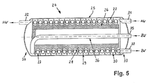
- the embodiment of a heat exchanger shown in Figure 5 24 in turn comprises a container 25, an inner one central insert 26 and a coiled tubing 27.
- the insert 26 is made of a hollow cylinder 28 made of a thermoplastic Plastic formed, on the outer periphery 29 a helical Groove 30 is formed. In the groove 30 is the Pipe coil 27 performed.
- the installation position of the heat exchanger 24 shown is horizontal.
- the heat exchanger has 24 via a heating water inlet 31 and a heating water outlet 32, which on the opposite end sides 33 or 34 of the heat exchanger 24.
- the process water BW is fed through inlet 35 and through the pipe section 36 first passed to the end side 34 before it through the Pipe coil 27 flows to the outlet 37.
- Process water BW becomes the heating water HW of the helical Following groove 30 to the heating water outlet 32, where it leaves the heat exchanger 24.
- the contact path for the transfer of thermal energy from the heating water HW on the process water flowing through the spiral tube 27 BW is therefore long enough to be an intense one Heat exchange takes place.
Landscapes
- Engineering & Computer Science (AREA)
- Physics & Mathematics (AREA)
- Thermal Sciences (AREA)
- Mechanical Engineering (AREA)
- General Engineering & Computer Science (AREA)
- Water Supply & Treatment (AREA)
- Chemical & Material Sciences (AREA)
- Combustion & Propulsion (AREA)
- Heat-Exchange Devices With Radiators And Conduit Assemblies (AREA)
- Treatment Of Water By Ion Exchange (AREA)
- Sorption Type Refrigeration Machines (AREA)
Abstract
Description
- Figur 1
- eine Ausführungsform eines Wärmetauschers im vertikalen Längsschnitt;
- Figur 2
- in vergrößerter Darstellung den Ausschnitt II der Figur 1;
- Figur 3
- in vergrößerter Darstellung den Ausschnitt III der Figur 2;
- Figur 4
- in vergrößerter Darstellung den Ausschnitt IV der Figur 2 und
- Figur 5
- ebenfalls im vertikalen Längsschnitt eine weitere Ausführungsform eines Wärmetauschers.
- 1
- - Wärmetauscher
- 2
- - Behälter
- 3
- - Einsatz
- 4
- - Rohr
- 5
- - Rohrwendel
- 6
- - Außenumfang v. 3
- 7
- - Nut
- 8
- - Oberfläche v. 3
- 9
- - Innenwand v. 2
- 10
- - Ringraum
- 11
- - Einlaß v. 5
- 12
- - Rohrabschnitt
- 13
- - Auslaß
- 14
- - Heizwassereinlaß
- 15
- - innerer Kanal v. 3
- 16
- - Endseite v. 1
- 17
- - Heizwasserauslaß
- 18
- - Flanke v. 7
- 19
- - Flanke v. 7
- 20
- - Ende
- 21
- - Fixierungselemente
- 22
- - Wulst
- 23
- - Wulst
- 24
- - Wärmetauscher
- 25
- - Behälter
- 26
- - Einsatz
- 27
- - Rohrwendel
- 28
- - Hohlzylinder
- 29
- - Außenumfang v. 26
- 30
- - Nut
- 31
- - Heizwassereinlaß
- 32
- - Heizwasserauslaß
- 33
- - Endseite v. 24
- 34
- - Endseite v. 24
- 35
- - Einlaß
- 36
- - Rohrabschnitt
- 37
- - Auslaß
- BW
- - Brauchwasser
- HW
- - Heizwasser
Claims (8)
- Wärmetauscher zur Brauchwasserbereitung, bei welchem eine Rohrwendel (5, 27) zur Führung von Brauchwasser in einem Behälter (2, 25) um einen zentralen Einsatz (3, 26) angeordnet und der Behälter (2, 25) mit Heizwasser beaufschlagbar ist, dadurch gekennzeichnet, daß die Rohrwendel (5, 27) in einer umfangsseitig des Einsatzes (3, 26) verlaufenden schraubenlinienförmigen Nut (7, 30) angeordnet und das Heizwasser in der Nut (7, 30) geführt ist.
- Wärmetauscher nach Anspruch 1, dadurch gekennzeichnet, daß die Nut (7, 30) am Außenumfang (6, 29) des Einsatzes (3, 26) ausgeformt ist.
- Wärmetauscher nach Anspruch 2, dadurch gekennzeichnet, daß der genutete Einsatz (3) mit seiner äußeren Oberfläche (8) die Innenwand (9) des Behälters (3) mediendicht kontaktiert.
- Wärmetauscher nach einem der Ansprüche 2 oder 3, dadurch gekennzeichnet, daß die Flanken (18, 19) der Nut (7) in Richtung auf die Innenwand (9) sich lippenartig verjüngend auslaufen.
- Wärmetauscher nach einem der Ansprüche 1 bis 4, dadurch gekennzeichnet, daß in der Nut (7) Fixierungselemente (21) für die Rohrwendel (5) angeordnet sind.
- Wärmetauscher nach Anspruch 5, dadurch gekennzeichnet, daß die Fixierungselemente (21) aus an den Flanken (18, 19) vorgesehenen Wulsten (22, 23) gebildet sind.
- Wärmetauscher nach einem der Ansprüche 1 bis 6, dadurch gekennzeichnet, daß der Einsatz (3, 26) aus einem thermoplastischen Kunststoff besteht.
- Wärmetauscher nach einem der Ansprüche 1 bis 7, dadurch gekennzeichnet, daß der Einsatz (3) einen inneren Kanal (15) aufweist.
Applications Claiming Priority (2)
| Application Number | Priority Date | Filing Date | Title |
|---|---|---|---|
| DE19628773 | 1996-07-17 | ||
| DE19628773A DE19628773A1 (de) | 1996-07-17 | 1996-07-17 | Wärmetauscher zur Brauchwasserbereitung |
Publications (3)
| Publication Number | Publication Date |
|---|---|
| EP0819892A2 true EP0819892A2 (de) | 1998-01-21 |
| EP0819892A3 EP0819892A3 (de) | 1999-01-27 |
| EP0819892B1 EP0819892B1 (de) | 2003-05-02 |
Family
ID=7800043
Family Applications (1)
| Application Number | Title | Priority Date | Filing Date |
|---|---|---|---|
| EP97111705A Expired - Lifetime EP0819892B1 (de) | 1996-07-17 | 1997-07-10 | Wärmetauscher zur Brauchwasserbereitung |
Country Status (6)
| Country | Link |
|---|---|
| EP (1) | EP0819892B1 (de) |
| AT (1) | ATE239196T1 (de) |
| DE (2) | DE19628773A1 (de) |
| DK (1) | DK0819892T3 (de) |
| ES (1) | ES2198517T3 (de) |
| PT (1) | PT819892E (de) |
Cited By (8)
| Publication number | Priority date | Publication date | Assignee | Title |
|---|---|---|---|---|
| EP1026467A2 (de) | 1999-02-05 | 2000-08-09 | Patente Rehberg Lauer | Plattenwärmeübertrager für Warmwasserbereitung und -speicherung |
| EP2762821A1 (de) * | 2013-02-01 | 2014-08-06 | LG Electronics, Inc. | Klimaanlage und Wärmetauscher dafür |
| CN104807350A (zh) * | 2015-05-05 | 2015-07-29 | 宁波德业科技集团有限公司 | 一种空调热交换器 |
| US9212852B2 (en) | 2012-07-11 | 2015-12-15 | Lg Electronics Inc. | Support mechanism for a heat exchanger in an air-conditioning system |
| US9389026B2 (en) | 2012-07-11 | 2016-07-12 | Lg Electronics Inc. | Heat exchanger |
| CN107238096A (zh) * | 2017-06-07 | 2017-10-10 | 汕头市合力环保节能技术有限公司 | 一种煤气节能装置 |
| WO2019161785A1 (zh) * | 2018-02-24 | 2019-08-29 | 三花控股集团有限公司 | 气液分离器及换热系统 |
| KR20200135103A (ko) * | 2019-05-23 | 2020-12-02 | 이삼해 | 유체 히팅 장치 및 그 제조 방법 |
Families Citing this family (3)
| Publication number | Priority date | Publication date | Assignee | Title |
|---|---|---|---|---|
| DE202006004396U1 (de) * | 2006-03-17 | 2007-05-10 | Viessmann Werke Gmbh & Co Kg | Wärmespeicher |
| DE102008059541A1 (de) * | 2008-11-30 | 2010-06-02 | Solarhybrid Ag | Wärmetauscher |
| DE102017218973A1 (de) * | 2017-10-24 | 2019-04-25 | Hanon Systems | Gegenstrom-Wärmeübertrager |
Citations (1)
| Publication number | Priority date | Publication date | Assignee | Title |
|---|---|---|---|---|
| EP0178351B1 (de) | 1984-10-15 | 1988-05-04 | Plaatverwerkende Industrie van Wijk en Boerma B.V. | Wassererhitzer z.B. Verbrauchswarmwasserbereiter |
Family Cites Families (4)
| Publication number | Priority date | Publication date | Assignee | Title |
|---|---|---|---|---|
| US2146141A (en) * | 1936-12-05 | 1939-02-07 | Standard Oil Co | Heat exchanger |
| CH550985A (de) * | 1972-03-30 | 1974-06-28 | Ygnis Sa | Waermetauscher. |
| JPH0684852B2 (ja) * | 1986-01-20 | 1994-10-26 | 株式会社東芝 | 極低温冷凍機 |
| NL194651C (nl) * | 1988-07-27 | 2002-10-04 | Meppeler Machf Nv | Tapwater-verwarmingsinrichting. |
-
1996
- 1996-07-17 DE DE19628773A patent/DE19628773A1/de not_active Ceased
-
1997
- 1997-07-10 AT AT97111705T patent/ATE239196T1/de active
- 1997-07-10 PT PT97111705T patent/PT819892E/pt unknown
- 1997-07-10 DK DK97111705T patent/DK0819892T3/da active
- 1997-07-10 ES ES97111705T patent/ES2198517T3/es not_active Expired - Lifetime
- 1997-07-10 DE DE59709951T patent/DE59709951D1/de not_active Expired - Lifetime
- 1997-07-10 EP EP97111705A patent/EP0819892B1/de not_active Expired - Lifetime
Patent Citations (1)
| Publication number | Priority date | Publication date | Assignee | Title |
|---|---|---|---|---|
| EP0178351B1 (de) | 1984-10-15 | 1988-05-04 | Plaatverwerkende Industrie van Wijk en Boerma B.V. | Wassererhitzer z.B. Verbrauchswarmwasserbereiter |
Cited By (12)
| Publication number | Priority date | Publication date | Assignee | Title |
|---|---|---|---|---|
| EP1026467A2 (de) | 1999-02-05 | 2000-08-09 | Patente Rehberg Lauer | Plattenwärmeübertrager für Warmwasserbereitung und -speicherung |
| DE19906180C2 (de) * | 1999-02-05 | 2003-02-06 | Peter Rehberg | Plattenwärmeübertrager für Warmwasserbereitung und -speicherung |
| US9212852B2 (en) | 2012-07-11 | 2015-12-15 | Lg Electronics Inc. | Support mechanism for a heat exchanger in an air-conditioning system |
| US9389026B2 (en) | 2012-07-11 | 2016-07-12 | Lg Electronics Inc. | Heat exchanger |
| EP2762821A1 (de) * | 2013-02-01 | 2014-08-06 | LG Electronics, Inc. | Klimaanlage und Wärmetauscher dafür |
| US9677819B2 (en) | 2013-02-01 | 2017-06-13 | Lg Electronics Inc. | Air conditioner and heat exchanger therefor |
| CN104807350A (zh) * | 2015-05-05 | 2015-07-29 | 宁波德业科技集团有限公司 | 一种空调热交换器 |
| CN104807350B (zh) * | 2015-05-05 | 2016-11-16 | 宁波德业科技集团有限公司 | 一种空调热交换器 |
| CN107238096A (zh) * | 2017-06-07 | 2017-10-10 | 汕头市合力环保节能技术有限公司 | 一种煤气节能装置 |
| WO2019161785A1 (zh) * | 2018-02-24 | 2019-08-29 | 三花控股集团有限公司 | 气液分离器及换热系统 |
| US11573036B2 (en) | 2018-02-24 | 2023-02-07 | Sanhua Holding Group, Co., Ltd. | Gas-liquid separator and heat exchange system |
| KR20200135103A (ko) * | 2019-05-23 | 2020-12-02 | 이삼해 | 유체 히팅 장치 및 그 제조 방법 |
Also Published As
| Publication number | Publication date |
|---|---|
| EP0819892A3 (de) | 1999-01-27 |
| DE59709951D1 (de) | 2003-06-05 |
| PT819892E (pt) | 2003-09-30 |
| ES2198517T3 (es) | 2004-02-01 |
| DK0819892T3 (da) | 2003-08-25 |
| DE19628773A1 (de) | 1998-01-22 |
| ATE239196T1 (de) | 2003-05-15 |
| EP0819892B1 (de) | 2003-05-02 |
Similar Documents
| Publication | Publication Date | Title |
|---|---|---|
| DE2728971C3 (de) | Einsatz für ein Wärmetauscherrohr | |
| EP2165143B1 (de) | Wärmetauscher | |
| DE2607501A1 (de) | Bewaesserungsvorrichtung | |
| EP0819892B1 (de) | Wärmetauscher zur Brauchwasserbereitung | |
| DE19810283A1 (de) | Permanentmagnetisches Flüssigkeitsbehandlungsgerät | |
| DE3017574A1 (de) | Koaxiales rohrsystem fuer die waermeuebertragung zwischen fluessigkeiten oder gasen | |
| DE202009009910U1 (de) | Wärmetauscher mit Strömungsumlenker | |
| DE2837802A1 (de) | Mit grosser uebertragungsflaeche versehene koerper, welche bei der herstellung von waermeaustauschapparaturen angewendet werden | |
| EP0814312B1 (de) | Verfahren zur Herstellung eines gewendelten Koaxialrohrs für einen Wärmetauscher und Wärmetauscher, der ein gewendeltes Koaxialrohr aufweist | |
| AT406798B (de) | Wärmetauscher zur rückgewinnung der in abwässern enthaltenen abwärme | |
| EP0627607B1 (de) | Dampfbeheizter Wärmeübertrager | |
| EP2304305B1 (de) | Rohrreduzierstück aus einem kunststoffmaterial | |
| DE3419304A1 (de) | Leitungsrohr zu installationszwecken | |
| EP1340953B1 (de) | Wärmetauscher, insbesondere für Schwimmbäder | |
| EP0674148A1 (de) | Heizkörper | |
| DE2708377A1 (de) | Rohrfoermiger waermetauscher | |
| DE102019133198B4 (de) | Durchströmungsvorrichtung zum Verwirbeln von Trinkwasser | |
| DE1778362A1 (de) | Waermeaustauschkoerper und Verfahren zu seiner Herstellung | |
| DE3047736A1 (de) | Waermeaustauscher mit einem gewendelten doppelrohr | |
| DE3519315A1 (de) | Waermetauscher aus einem huellrohr und einem im innern des huellrohres angeordneten wendelartig verlaufenden rohr | |
| DE3321456A1 (de) | Durchwirbeleinrichtung fuer einen ein rohrbuendel aufweisenden waermetauscher und waermetauscher mit solchen durchwirbeleinrichtungen | |
| EP1216206B1 (de) | Permanentmagnetisches flüssigkeitsbehandlungsgerät | |
| EP2295888B1 (de) | Wassererwärmer | |
| CH670881A5 (de) | ||
| DE2912011B2 (de) | Rohrregister für einen Durchlauferhitzer |
Legal Events
| Date | Code | Title | Description |
|---|---|---|---|
| PUAI | Public reference made under article 153(3) epc to a published international application that has entered the european phase |
Free format text: ORIGINAL CODE: 0009012 |
|
| AK | Designated contracting states |
Kind code of ref document: A2 Designated state(s): AT BE CH DE DK ES FI FR GB GR IE IT LI LU MC NL PT SE |
|
| PUAL | Search report despatched |
Free format text: ORIGINAL CODE: 0009013 |
|
| AK | Designated contracting states |
Kind code of ref document: A3 Designated state(s): AT BE CH DE DK ES FI FR GB GR IE IT LI LU MC NL PT SE |
|
| 17P | Request for examination filed |
Effective date: 19990722 |
|
| AKX | Designation fees paid |
Free format text: AT BE CH DE DK ES FI FR GB GR IE IT LI LU MC NL PT |
|
| RBV | Designated contracting states (corrected) |
Designated state(s): AT BE CH DE DK ES FI FR GB GR IE IT LI LU MC NL PT SE |
|
| 17Q | First examination report despatched |
Effective date: 20020507 |
|
| GRAH | Despatch of communication of intention to grant a patent |
Free format text: ORIGINAL CODE: EPIDOS IGRA |
|
| GRAH | Despatch of communication of intention to grant a patent |
Free format text: ORIGINAL CODE: EPIDOS IGRA |
|
| GRAA | (expected) grant |
Free format text: ORIGINAL CODE: 0009210 |
|
| AK | Designated contracting states |
Designated state(s): AT BE CH DE DK ES FI FR GB GR IE IT LI LU MC NL PT SE |
|
| REG | Reference to a national code |
Ref country code: GB Ref legal event code: FG4D Free format text: NOT ENGLISH |
|
| REG | Reference to a national code |
Ref country code: CH Ref legal event code: EP |
|
| REF | Corresponds to: |
Ref document number: 59709951 Country of ref document: DE Date of ref document: 20030605 Kind code of ref document: P |
|
| REG | Reference to a national code |
Ref country code: IE Ref legal event code: FG4D Free format text: GERMAN |
|
| REG | Reference to a national code |
Ref country code: SE Ref legal event code: TRGR |
|
| REG | Reference to a national code |
Ref country code: CH Ref legal event code: NV Representative=s name: OK PAT AG PATENTE MARKEN LIZENZEN |
|
| REG | Reference to a national code |
Ref country code: DK Ref legal event code: T3 |
|
| REG | Reference to a national code |
Ref country code: GR Ref legal event code: EP Ref document number: 20030402966 Country of ref document: GR |
|
| GBT | Gb: translation of ep patent filed (gb section 77(6)(a)/1977) | ||
| REG | Reference to a national code |
Ref country code: PT Ref legal event code: SC4A Free format text: AVAILABILITY OF NATIONAL TRANSLATION Effective date: 20030801 |
|
| ET | Fr: translation filed | ||
| REG | Reference to a national code |
Ref country code: ES Ref legal event code: FG2A Ref document number: 2198517 Country of ref document: ES Kind code of ref document: T3 |
|
| PLBE | No opposition filed within time limit |
Free format text: ORIGINAL CODE: 0009261 |
|
| STAA | Information on the status of an ep patent application or granted ep patent |
Free format text: STATUS: NO OPPOSITION FILED WITHIN TIME LIMIT |
|
| 26N | No opposition filed |
Effective date: 20040203 |
|
| REG | Reference to a national code |
Ref country code: CH Ref legal event code: PFA Owner name: KME VERWALTUNGS- UND DIENSTLEISTUNGSGESELLSCHAFT Free format text: KME SCHMOELE GMBH#HOENNENWERTH 13#58706 MENDEN (DE) -TRANSFER TO- KME VERWALTUNGS- UND DIENSTLEISTUNGSGESELLSCHAFT GMBH#KLOSTERSTRASSE 29#49074 OSNABRUECK (DE) |
|
| REG | Reference to a national code |
Ref country code: CH Ref legal event code: PK Free format text: BERICHTIGUNG. Ref country code: CH Ref legal event code: PK Free format text: KORREKTUR DES FIRMENNAMENS |
|
| NLT1 | Nl: modifications of names registered in virtue of documents presented to the patent office pursuant to art. 16 a, paragraph 1 |
Owner name: KME VERWALTUNGS- UND DIENSTLEISTUNGSGESELLSCHAFT M |
|
| REG | Reference to a national code |
Ref country code: PT Ref legal event code: PD4A Owner name: KME VERWALTUNGS UND DIENSTLEITUNGSGESELLSCHAFT, DE Effective date: 20061011 |
|
| REG | Reference to a national code |
Ref country code: FR Ref legal event code: CD |
|
| REG | Reference to a national code |
Ref country code: CH Ref legal event code: PCAR Free format text: ALDO ROEMPLER PATENTANWALT;BRENDENWEG 11 POSTFACH 154;9424 RHEINECK (CH) |
|
| REG | Reference to a national code |
Ref country code: FR Ref legal event code: PLFP Year of fee payment: 19 |
|
| PGFP | Annual fee paid to national office [announced via postgrant information from national office to epo] |
Ref country code: LU Payment date: 20150824 Year of fee payment: 19 Ref country code: NL Payment date: 20150722 Year of fee payment: 19 |
|
| PGFP | Annual fee paid to national office [announced via postgrant information from national office to epo] |
Ref country code: ES Payment date: 20150827 Year of fee payment: 19 Ref country code: IE Payment date: 20150723 Year of fee payment: 19 Ref country code: GB Payment date: 20150727 Year of fee payment: 19 Ref country code: CH Payment date: 20150722 Year of fee payment: 19 Ref country code: MC Payment date: 20150722 Year of fee payment: 19 Ref country code: FI Payment date: 20150721 Year of fee payment: 19 Ref country code: PT Payment date: 20150706 Year of fee payment: 19 Ref country code: DK Payment date: 20150728 Year of fee payment: 19 |
|
| PGFP | Annual fee paid to national office [announced via postgrant information from national office to epo] |
Ref country code: GR Payment date: 20150727 Year of fee payment: 19 Ref country code: SE Payment date: 20150731 Year of fee payment: 19 Ref country code: BE Payment date: 20150731 Year of fee payment: 19 Ref country code: AT Payment date: 20150729 Year of fee payment: 19 Ref country code: FR Payment date: 20150728 Year of fee payment: 19 |
|
| PGFP | Annual fee paid to national office [announced via postgrant information from national office to epo] |
Ref country code: IT Payment date: 20150729 Year of fee payment: 19 |
|
| PGFP | Annual fee paid to national office [announced via postgrant information from national office to epo] |
Ref country code: DE Payment date: 20150930 Year of fee payment: 19 |
|
| PG25 | Lapsed in a contracting state [announced via postgrant information from national office to epo] |
Ref country code: BE Free format text: LAPSE BECAUSE OF NON-PAYMENT OF DUE FEES Effective date: 20160731 |
|
| REG | Reference to a national code |
Ref country code: DE Ref legal event code: R119 Ref document number: 59709951 Country of ref document: DE |
|
| REG | Reference to a national code |
Ref country code: DK Ref legal event code: EBP Effective date: 20170131 |
|
| REG | Reference to a national code |
Ref country code: CH Ref legal event code: PL |
|
| REG | Reference to a national code |
Ref country code: NL Ref legal event code: MM Effective date: 20160801 |
|
| REG | Reference to a national code |
Ref country code: SE Ref legal event code: EUG |
|
| REG | Reference to a national code |
Ref country code: AT Ref legal event code: MM01 Ref document number: 239196 Country of ref document: AT Kind code of ref document: T Effective date: 20160710 |
|
| GBPC | Gb: european patent ceased through non-payment of renewal fee |
Effective date: 20160710 |
|
| PG25 | Lapsed in a contracting state [announced via postgrant information from national office to epo] |
Ref country code: MC Free format text: LAPSE BECAUSE OF NON-PAYMENT OF DUE FEES Effective date: 20160801 |
|
| REG | Reference to a national code |
Ref country code: GR Ref legal event code: ML Ref document number: 20030402966 Country of ref document: GR Effective date: 20170207 |
|
| PG25 | Lapsed in a contracting state [announced via postgrant information from national office to epo] |
Ref country code: NL Free format text: LAPSE BECAUSE OF NON-PAYMENT OF DUE FEES Effective date: 20160801 Ref country code: SE Free format text: LAPSE BECAUSE OF NON-PAYMENT OF DUE FEES Effective date: 20160711 Ref country code: GR Free format text: LAPSE BECAUSE OF NON-PAYMENT OF DUE FEES Effective date: 20170207 Ref country code: LI Free format text: LAPSE BECAUSE OF NON-PAYMENT OF DUE FEES Effective date: 20160731 Ref country code: CH Free format text: LAPSE BECAUSE OF NON-PAYMENT OF DUE FEES Effective date: 20160731 Ref country code: FI Free format text: LAPSE BECAUSE OF NON-PAYMENT OF DUE FEES Effective date: 20160710 Ref country code: FR Free format text: LAPSE BECAUSE OF NON-PAYMENT OF DUE FEES Effective date: 20160801 Ref country code: DE Free format text: LAPSE BECAUSE OF NON-PAYMENT OF DUE FEES Effective date: 20170201 |
|
| REG | Reference to a national code |
Ref country code: FR Ref legal event code: ST Effective date: 20170331 |
|
| REG | Reference to a national code |
Ref country code: IE Ref legal event code: MM4A |
|
| PG25 | Lapsed in a contracting state [announced via postgrant information from national office to epo] |
Ref country code: GB Free format text: LAPSE BECAUSE OF NON-PAYMENT OF DUE FEES Effective date: 20160710 Ref country code: AT Free format text: LAPSE BECAUSE OF NON-PAYMENT OF DUE FEES Effective date: 20160710 Ref country code: PT Free format text: LAPSE BECAUSE OF NON-PAYMENT OF DUE FEES Effective date: 20170110 |
|
| PG25 | Lapsed in a contracting state [announced via postgrant information from national office to epo] |
Ref country code: IE Free format text: LAPSE BECAUSE OF NON-PAYMENT OF DUE FEES Effective date: 20160710 |
|
| PG25 | Lapsed in a contracting state [announced via postgrant information from national office to epo] |
Ref country code: IT Free format text: LAPSE BECAUSE OF NON-PAYMENT OF DUE FEES Effective date: 20160710 Ref country code: LU Free format text: LAPSE BECAUSE OF NON-PAYMENT OF DUE FEES Effective date: 20160710 |
|
| PG25 | Lapsed in a contracting state [announced via postgrant information from national office to epo] |
Ref country code: PT Free format text: LAPSE BECAUSE OF EXPIRATION OF PROTECTION Effective date: 20170718 |
|
| PG25 | Lapsed in a contracting state [announced via postgrant information from national office to epo] |
Ref country code: DK Free format text: LAPSE BECAUSE OF NON-PAYMENT OF DUE FEES Effective date: 20160731 |
|
| REG | Reference to a national code |
Ref country code: ES Ref legal event code: FD2A Effective date: 20180507 |
|
| PG25 | Lapsed in a contracting state [announced via postgrant information from national office to epo] |
Ref country code: ES Free format text: LAPSE BECAUSE OF NON-PAYMENT OF DUE FEES Effective date: 20160711 |
|
| PG25 | Lapsed in a contracting state [announced via postgrant information from national office to epo] |
Ref country code: PT Free format text: LAPSE BECAUSE OF EXPIRATION OF PROTECTION Effective date: 20150710 |