EP0818659A2 - Distributeur pour des médias différents dans des circuits d'alimentation, spécialement dans des systèmes de chauffage et méthode de production - Google Patents
Distributeur pour des médias différents dans des circuits d'alimentation, spécialement dans des systèmes de chauffage et méthode de production Download PDFInfo
- Publication number
- EP0818659A2 EP0818659A2 EP97111579A EP97111579A EP0818659A2 EP 0818659 A2 EP0818659 A2 EP 0818659A2 EP 97111579 A EP97111579 A EP 97111579A EP 97111579 A EP97111579 A EP 97111579A EP 0818659 A2 EP0818659 A2 EP 0818659A2
- Authority
- EP
- European Patent Office
- Prior art keywords
- distributor
- pipe
- partition
- return
- flow
- Prior art date
- Legal status (The legal status is an assumption and is not a legal conclusion. Google has not performed a legal analysis and makes no representation as to the accuracy of the status listed.)
- Withdrawn
Links
- 238000000034 method Methods 0.000 title claims description 22
- 238000010438 heat treatment Methods 0.000 title claims description 7
- 238000009434 installation Methods 0.000 title 1
- 238000005192 partition Methods 0.000 claims abstract description 94
- 238000000926 separation method Methods 0.000 claims description 25
- 238000003466 welding Methods 0.000 claims description 23
- XEEYBQQBJWHFJM-UHFFFAOYSA-N Iron Chemical compound [Fe] XEEYBQQBJWHFJM-UHFFFAOYSA-N 0.000 claims description 11
- 238000009826 distribution Methods 0.000 claims description 9
- 238000004519 manufacturing process Methods 0.000 claims description 8
- 229920000573 polyethylene Polymers 0.000 claims description 8
- RYGMFSIKBFXOCR-UHFFFAOYSA-N Copper Chemical compound [Cu] RYGMFSIKBFXOCR-UHFFFAOYSA-N 0.000 claims description 6
- 239000010949 copper Substances 0.000 claims description 5
- 229910052802 copper Inorganic materials 0.000 claims description 5
- 229910052742 iron Inorganic materials 0.000 claims description 5
- -1 polyethylene Polymers 0.000 claims description 5
- 239000004698 Polyethylene Substances 0.000 claims description 4
- 229910052751 metal Inorganic materials 0.000 claims description 3
- 239000002184 metal Substances 0.000 claims description 3
- 229920003023 plastic Polymers 0.000 claims description 3
- 239000004033 plastic Substances 0.000 claims description 3
- 239000000463 material Substances 0.000 description 12
- 238000005452 bending Methods 0.000 description 6
- 238000005520 cutting process Methods 0.000 description 4
- 239000011810 insulating material Substances 0.000 description 3
- XLYOFNOQVPJJNP-UHFFFAOYSA-N water Substances O XLYOFNOQVPJJNP-UHFFFAOYSA-N 0.000 description 3
- 230000015572 biosynthetic process Effects 0.000 description 2
- 239000007789 gas Substances 0.000 description 2
- 239000013307 optical fiber Substances 0.000 description 2
- 230000000694 effects Effects 0.000 description 1
- 239000011261 inert gas Substances 0.000 description 1
- 238000009413 insulation Methods 0.000 description 1
- 239000012774 insulation material Substances 0.000 description 1
- 238000003754 machining Methods 0.000 description 1
- 239000000203 mixture Substances 0.000 description 1
- 230000010355 oscillation Effects 0.000 description 1
- 239000003973 paint Substances 0.000 description 1
- 230000005855 radiation Effects 0.000 description 1
- 230000003252 repetitive effect Effects 0.000 description 1
- WFKWXMTUELFFGS-UHFFFAOYSA-N tungsten Chemical compound [W] WFKWXMTUELFFGS-UHFFFAOYSA-N 0.000 description 1
- 229910052721 tungsten Inorganic materials 0.000 description 1
- 239000010937 tungsten Substances 0.000 description 1
Images


Classifications
-
- F—MECHANICAL ENGINEERING; LIGHTING; HEATING; WEAPONS; BLASTING
- F28—HEAT EXCHANGE IN GENERAL
- F28F—DETAILS OF HEAT-EXCHANGE AND HEAT-TRANSFER APPARATUS, OF GENERAL APPLICATION
- F28F9/00—Casings; Header boxes; Auxiliary supports for elements; Auxiliary members within casings
- F28F9/02—Header boxes; End plates
- F28F9/026—Header boxes; End plates with static flow control means, e.g. with means for uniformly distributing heat exchange media into conduits
- F28F9/0265—Header boxes; End plates with static flow control means, e.g. with means for uniformly distributing heat exchange media into conduits by using guiding means or impingement means inside the header box
-
- F—MECHANICAL ENGINEERING; LIGHTING; HEATING; WEAPONS; BLASTING
- F24—HEATING; RANGES; VENTILATING
- F24D—DOMESTIC- OR SPACE-HEATING SYSTEMS, e.g. CENTRAL HEATING SYSTEMS; DOMESTIC HOT-WATER SUPPLY SYSTEMS; ELEMENTS OR COMPONENTS THEREFOR
- F24D3/00—Hot-water central heating systems
- F24D3/10—Feed-line arrangements, e.g. providing for heat-accumulator tanks, expansion tanks ; Hydraulic components of a central heating system
- F24D3/1058—Feed-line arrangements, e.g. providing for heat-accumulator tanks, expansion tanks ; Hydraulic components of a central heating system disposition of pipes and pipe connections
- F24D3/1066—Distributors for heating liquids
Definitions
- the invention relates to a device for distribution different media in supply systems, in particular in heating systems and processes for their manufacture.
- a facility of the type mentioned is through the Comfort-Sinusverteiler GmbH, D-48493 Wettringen.
- the facility consists of a cuboid Hollow body that resembles a sinusoid inside corrugated partition is divided. On a straight track are a main flow and a return main on one side and on the opposite side several supply and return lines arranged. This allows all lines in one Row and side by side.
- the one in the hollow body running partition however, caused in Forward and return section repetitive cross-sectional constrictions and increases the flow rate influence. Through this and through the cuboidal formation, there can be tension in the hollow body come. The hollow body warps and can even break.
- a main distributor is known from CH-PS 443 602. He consists of a tube that is closed at both ends is. There is a partition in it so that two cylindrical parts are created. Although here Flow and return sections of the same size, however, the supply and return lines are not in installable on a straight track. This will make additional Bending work required.
- the Task also refers to a procedure to specify to manufacture this facility.
- the advantages achieved with the invention are in particular in that through the use of a manifold with a round and / or oval cross section no internal tensions. This warps the manifold not and minimize breakage losses yourself. These effects are through the specially trained Partition increased. Because the partition is sinusoidal curled and beyond at an angle the cross-sectional center line is pivoted back and forth, a distributor feed pipe and a distributor return partial pipe are formed same cross-section. This improves the flow rate of the to be distributed Medium, especially water. It should be emphasized that the use of a manifold, especially with a round cross section, is significantly cheaper than a specially made cuboid hollow body. Through the use of the particularly round manifold with the specially designed partition, it is possible the advantage of arranging the supply and return lines on one track and the advantage of the same partial cross-section to couple with each other.
- the partition There are two options for arranging the partition: On the one hand, it can be arranged between the distributor feed pipe and the distributor return pipe.
- the distributor pipe and / or the partition can be made of metal, especially iron or copper, or made of plastic, especially polyethylene. Which one Material used depends on the particular Conditions.
- the angle by which the partition swings back and forth can be from ⁇ 10 to ⁇ 20 °, preferably ⁇ 15 ° be.
- the advantages associated with this method exist especially in that when using a round or oval tube cross-sectionally into two of the same Distribution pipes are separated.
- the partition has no cross-sectional influence.
- Another The advantage is that the partition is heat-insulating can be. This is realized in such a way that the Partition is divided into two partitions, between to which an insulating material is introduced. By a connection of the two partitions with the one in between Such a thermal insulation layer can Connect the partition to the two distributor pipes.
- the partition is prepared so that they are inserted into the interior of the manifold and then connected to it.
- the partition itself mainly consists of to produce an isolatable material that at most on its opposite edges with a material is provided, which corresponds to that of the manifold.
- the formation of the partition 4 is essential to the invention.
- the main track opposite along the distributor track 10 10 'running return separation curve 14 is opposite the lead separation curve 13 out of phase.
- the return separation curve 14 has the same amplitude A and the same Partition forward vibration bend 4V or partition wall return vibration bend 4R.
- the main distributor is manufactured as follows:
- the distributor pipe 1 is along the flow separation curve 13 and the return separation curve 14, as in FIG. 4 shows, in a partial body, the distributor feed pipe 11 and a body that the distributor return pipe 12 corresponds to divided.
- the recesses for the flow lines and the return lines and the main flow line 7 and the main return line 10 in the manifold be introduced. Cutting the manifold 1 in the manner described can with a program-controlled cutting system will.
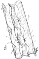
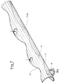
- the individual body of the distributor feed pipe 11 and the distributor return partial pipe 12, as shown in FIG. 5 and Figures 7 and 7 can be treated accordingly.
- Thermal insulation Materials can be easily and here Way inside the body of the distributor feed pipe 11 and the distributor return pipe 12 applied will.
- the partition 4 shown in Figs. 4 and 6 is made a partition blank 4 '.
- the blank partition 4 ' has a partition wall width 4D that is the manifold diameter 1D plus twice the wall thickness of the Distribution pipe 1 corresponds.
- the bending blank 4 ' is corrugated to the bending machine and pivoted back and forth about the partition wall angle ⁇ bent so that one side of the partition 4th along the forward separation curve 13 and the opposite Wall side runs along the return separation curve 14.
- the pivoting of the partition 4 takes place, as already described, by the partition wall bending angle ⁇ , which is ⁇ 15 ° opposite the center line is 9.
- the partition bending angle can also differ from the specified Swivel the number of degrees in the range between ⁇ 10 and ⁇ 20 °. Do the conditions of use make it necessary is a pivoting outside of the specified Range possible.
- the respective partition wall bending angle In principle, there are no limits. Decisive for the respective size are the respective ones especially prevailing conditions.
- the partition 4 can be designed to be heat-insulating.
- the partition 4 consists of a heat-insulating material.
- Another Possibility is that the partition 4 in two partitions that are compatible with each other are divided. There is an insulating layer between the two partitions introduced and both partitions to the partition 4 reconnected.
- the insulating layer can as a third partial partition made of insulating material or as a hollow body forming inside the partition 4, which is coated with heat-insulating paints will be realized.
- the distributor pipe 1 and the partition 4 can be made of metal, in particular iron or copper or plastic, especially polyethylene (PE).
- PE polyethylene
- Plasma welding can be connected to each other.
- the arc between the welding electrode and parts 4, 11 and 12 is additionally constricted by a nozzle. Thereby increases its intensity and stability. Through the Constriction creates a highly heated gas in the burner with high energy content, its electrical energy directly is converted into heat. This ionized gas, which transfers the arc to the workpiece referred to as plasma.
- the advantages of plasma welding consist of high-precision seams even on thin Materials can be manufactured. Due to the high Welding speed and the higher requirements is mechanization of the welding process possible.
- Another manufacturing variant for the main distributor is that in the round or oval manifold 1 the partition is inserted.
- the blank partition 4 'becomes in the manner already described Partition 4 similar to sinusoidal curves according to the respective application corrugated and around the cross-sectional center line 9 pivoted back and forth to the partition 4 bent. Then the partition 4 is turned so that the partition width 4D is equal to the 1D manifold diameter is.
- the opposite narrow edges that along the forward separation curve 13 and the return separation curve 14 run, are the curvature of the manifold customized.
- the partition 4 can also, as already described, designed to be heat-insulating.
- the Laser beam welding is particularly well suited for welding three-dimensional molded parts.
- the Beam guidance from the beam source to the processing location can be done using a flexible optical fiber. Focused at the exit point of the optical fiber a machining head made by a standard industrial robot the radiation is guided onto the workpiece surface.
- the laser beam welds are made with Speeds of several meters per minute and allow high strength. Because the inevitable Dimensional and shape tolerances of the three-dimensional Parts 4, 11 and 12 are typically a few millimeters will advantageously be seam tracking systems used to be a during the process Tracking the focus point according to the actual one To enable joint geometry. These seam tracking systems work on the basis of a line projection method with a CCD camera.
- the welding of the flow lines 2.1, ... 2.n, the Return lines 3.1, ... 3.n, the main flow line 7 and the main return line 8 is advantageously realized with the welding process that the least Makes expenses. It can therefore also use the welding process be that when manufacturing the main distributor Application.
- the hot water reaches the main flow line 7 in the distributor pipe 1. Because the distributor feed pipe 1 with the same partial cross-section TQV over the entire length of the distributor pipe 1 extends, the flow rate is restricted not limited. The same goes for that about the Return lines 3.1, ... 3.n incoming cooled Water, which is then discharged via the return line 8 becomes.
Landscapes
- Engineering & Computer Science (AREA)
- Physics & Mathematics (AREA)
- Thermal Sciences (AREA)
- Mechanical Engineering (AREA)
- General Engineering & Computer Science (AREA)
- Chemical & Material Sciences (AREA)
- Combustion & Propulsion (AREA)
- Branch Pipes, Bends, And The Like (AREA)
- Extrusion Moulding Of Plastics Or The Like (AREA)
- Steam Or Hot-Water Central Heating Systems (AREA)
Applications Claiming Priority (2)
| Application Number | Priority Date | Filing Date | Title |
|---|---|---|---|
| DE1996128351 DE19628351C2 (de) | 1996-07-13 | 1996-07-13 | Einrichtung zur Verteilung unterschiedlicher Medien in Versorgungsanlagen, insbesondere in Heizungsanlagen und Verfahren zu ihrer Herstellung |
| DE19628351 | 1996-07-13 |
Publications (2)
| Publication Number | Publication Date |
|---|---|
| EP0818659A2 true EP0818659A2 (fr) | 1998-01-14 |
| EP0818659A3 EP0818659A3 (fr) | 1999-01-07 |
Family
ID=7799786
Family Applications (1)
| Application Number | Title | Priority Date | Filing Date |
|---|---|---|---|
| EP97111579A Withdrawn EP0818659A3 (fr) | 1996-07-13 | 1997-07-09 | Distributeur pour des médias différents dans des circuits d'alimentation, spécialement dans des systèmes de chauffage et méthode de production |
Country Status (2)
| Country | Link |
|---|---|
| EP (1) | EP0818659A3 (fr) |
| DE (1) | DE19628351C2 (fr) |
Cited By (6)
| Publication number | Priority date | Publication date | Assignee | Title |
|---|---|---|---|---|
| FR2852672A1 (fr) * | 2003-03-17 | 2004-09-24 | Baelz Gmbh Helmut | Module de distribution de chaleur |
| EP1484570A2 (fr) | 2003-06-06 | 2004-12-08 | EISENMANN MASCHINENBAU KG (Komplementär: EISENMANN-Stiftung) | Distributeur de fluide caloporteur pour un dispositif d'alimentation en air comprenant plusieurs échangeurs de chaleur |
| EP1760407A1 (fr) * | 2005-09-05 | 2007-03-07 | Comfort-Sinusverteiler GmbH | Distributeur pour système de chauffage et de refroidissement |
| WO2011147966A3 (fr) * | 2010-05-27 | 2013-05-02 | Terence Gerard Madigan | Collecteur |
| IT201800003450A1 (it) * | 2018-03-12 | 2019-09-12 | Enolgas Bonomi S P A | Collettore di distribuzione |
| RU2701423C1 (ru) * | 2018-03-28 | 2019-09-26 | Манук Лусегенович Чориев | Гидравлический коллектор (варианты) |
Families Citing this family (1)
| Publication number | Priority date | Publication date | Assignee | Title |
|---|---|---|---|---|
| CN112503396A (zh) * | 2020-11-05 | 2021-03-16 | 扬子江药业集团广州海瑞药业有限公司 | 冷却注射用水排水控制方法及系统 |
Citations (1)
| Publication number | Priority date | Publication date | Assignee | Title |
|---|---|---|---|---|
| CH443602A (de) | 1962-07-23 | 1967-09-15 | Paulus Wolff Ingemar Filip | Verfahren zur Anordnung der Heizungs-, Kalt- und Warmwasserverbrauchsleitungen in Gebäuden und nach dem Verfahren hergestellte Anordnung |
Family Cites Families (4)
| Publication number | Priority date | Publication date | Assignee | Title |
|---|---|---|---|---|
| DE2659348C2 (de) * | 1976-12-29 | 1979-02-15 | Hubert 4430 Steinfurt Wessels | Rohrverteiler für Zentralheizungsanlagen |
| DE2718932A1 (de) * | 1977-04-28 | 1978-11-02 | Hans Warzecha | Verteiler-sammler-vorrichtung |
| DE3026086C2 (de) * | 1980-07-10 | 1982-05-27 | Artur 7531 Neulingen Schenk | Rohrverteiler für Zentralheizungsanlagen |
| DE3410073A1 (de) * | 1983-03-29 | 1984-10-04 | Hans Dipl.-Ing.(FH) 7345 Deggingen Straub | Verteilereinheit fuer die rohre von zentralheizungsanlagen und verfahren zu seiner herstellung |
-
1996
- 1996-07-13 DE DE1996128351 patent/DE19628351C2/de not_active Expired - Fee Related
-
1997
- 1997-07-09 EP EP97111579A patent/EP0818659A3/fr not_active Withdrawn
Patent Citations (1)
| Publication number | Priority date | Publication date | Assignee | Title |
|---|---|---|---|---|
| CH443602A (de) | 1962-07-23 | 1967-09-15 | Paulus Wolff Ingemar Filip | Verfahren zur Anordnung der Heizungs-, Kalt- und Warmwasserverbrauchsleitungen in Gebäuden und nach dem Verfahren hergestellte Anordnung |
Non-Patent Citations (1)
| Title |
|---|
| "Wichtig: Dosierung und Mischung", DER PRAKTIKER - SCHWEISSEN UND SCHNEIDEN JAHRGANG 48, June 1996 (1996-06-01), pages 254 - 258 |
Cited By (10)
| Publication number | Priority date | Publication date | Assignee | Title |
|---|---|---|---|---|
| FR2852672A1 (fr) * | 2003-03-17 | 2004-09-24 | Baelz Gmbh Helmut | Module de distribution de chaleur |
| DE10311532A1 (de) * | 2003-03-17 | 2004-10-07 | Helmut Bälz GmbH | Wärmeverteilermodul |
| DE10311532B4 (de) * | 2003-03-17 | 2008-04-17 | Helmut Bälz GmbH | Wärmeverteilermodul |
| EP1484570A2 (fr) | 2003-06-06 | 2004-12-08 | EISENMANN MASCHINENBAU KG (Komplementär: EISENMANN-Stiftung) | Distributeur de fluide caloporteur pour un dispositif d'alimentation en air comprenant plusieurs échangeurs de chaleur |
| EP1484570A3 (fr) * | 2003-06-06 | 2010-09-29 | EISENMANN Anlagenbau GmbH & Co. KG | Distributeur de fluide caloporteur pour un dispositif d'alimentation en air comprenant plusieurs échangeurs de chaleur |
| EP1760407A1 (fr) * | 2005-09-05 | 2007-03-07 | Comfort-Sinusverteiler GmbH | Distributeur pour système de chauffage et de refroidissement |
| WO2011147966A3 (fr) * | 2010-05-27 | 2013-05-02 | Terence Gerard Madigan | Collecteur |
| IT201800003450A1 (it) * | 2018-03-12 | 2019-09-12 | Enolgas Bonomi S P A | Collettore di distribuzione |
| EP3540317A1 (fr) * | 2018-03-12 | 2019-09-18 | Enolgas Bonomi S.p.A. | Collecteur |
| RU2701423C1 (ru) * | 2018-03-28 | 2019-09-26 | Манук Лусегенович Чориев | Гидравлический коллектор (варианты) |
Also Published As
| Publication number | Publication date |
|---|---|
| DE19628351C2 (de) | 1998-07-09 |
| EP0818659A3 (fr) | 1999-01-07 |
| DE19628351A1 (de) | 1998-01-15 |
Similar Documents
| Publication | Publication Date | Title |
|---|---|---|
| EP0660064B1 (fr) | Echangeur de chaleur | |
| DE3036427A1 (de) | Laserstrahl-reflexionssystem | |
| DE102010028745A1 (de) | Verfahren und Vorrichtung zum mechanisierten Schweißen von Stumpfstößen an ebenen Blechen oder an Rohren mit einer Blech- bzw. einer Wanddicke von bis zu 12 mm und darüber hinaus unter Verwendung einer Prozesskombination, bestehend aus Laser-MSG-Hybrid- und MSG-Technik | |
| DE102015207279A1 (de) | Fügevorrichtung und Fügeverfahren | |
| DE1550651B1 (de) | Stroemungsmittelleitungssystem,insbesondere fuer einen Stroemungsmittelverstaerker oder Oszillato | |
| EP2216123A1 (fr) | Tuyau à gaz de protection et tuyau de contact d'un dispositif destiné à la soudure améliorée d'intervalles serrés | |
| DE102012017130B4 (de) | Laser-Rohreinschweißen | |
| DE3834080C2 (fr) | ||
| EP0169564A2 (fr) | Procédé et dispositif pour plier des objets longs, en particulier des tubes | |
| EP0781623A1 (fr) | Procédé pour la fabrication d'échangeurs de la chaleur en aluminium par brasage | |
| DE102007018387B4 (de) | Durchlaufschweißmaschine zum Verschweißen eines Rohrrohlings | |
| EP0818659A2 (fr) | Distributeur pour des médias différents dans des circuits d'alimentation, spécialement dans des systèmes de chauffage et méthode de production | |
| DE2308480A1 (de) | Waermetauscher | |
| EP1270132B1 (fr) | Corps de base constitué de tronçons de tube joints et procédé de fabrication | |
| DE4017634A1 (de) | Verfahren und vorrichtung zur kontinuierlichen herstellung von geschweisstem metallrohr | |
| DE19631534C2 (de) | Verfahren und Vorrichtung zum kontinuierlichen, spanlosen Zerteilen eines rohrförmigen Werkstückes in einzelne, untereinander gleiche Ringe | |
| DE2253760A1 (de) | Verfahren und vorrichtung zur herstellung von waermetauschern | |
| DE102020125290B4 (de) | Verfahren und Vorrichtung zum Schweißen von Kunststoffteilen | |
| DE102020116437B4 (de) | Verfahren und Vorrichtung zur Herstellung eines Rippenrohres | |
| EP0108423B1 (fr) | Procédé et dispositif pour enrober d'une manière continue des tuyaux en matière synthétique dans une enveloppe de protection | |
| DE102020131560B3 (de) | Verfahren und Vorrichtung zur Herstellung von Rippenrohren | |
| DE4141372C2 (de) | Vorrichtung zum Abrunden der Borstenenden von runden beziehungsweise rotationssymmetrischen Bürsten | |
| DE2656804A1 (de) | Verfahren zum t- oder stumpfschweissen von laminiertem vollsynthetischem material | |
| EP0166796A1 (fr) | Procédé de fabrication de raccords extrudés en forme de T et de L en acier de basse teneur en carbone pour des radiateurs plats | |
| DE1583333B1 (de) | Induktor zum Oberflaechenhaerten von langgestreckten mit einem Flansch versehenen Werkstuecken unterschiedlichen Durchmessers |
Legal Events
| Date | Code | Title | Description |
|---|---|---|---|
| PUAI | Public reference made under article 153(3) epc to a published international application that has entered the european phase |
Free format text: ORIGINAL CODE: 0009012 |
|
| AK | Designated contracting states |
Kind code of ref document: A2 Designated state(s): AT BE CH DK FR LI NL |
|
| PUAL | Search report despatched |
Free format text: ORIGINAL CODE: 0009013 |
|
| AK | Designated contracting states |
Kind code of ref document: A3 Designated state(s): AT BE CH DE DK ES FI FR GB GR IE IT LI LU MC NL PT SE |
|
| 17P | Request for examination filed |
Effective date: 19990521 |
|
| AKX | Designation fees paid |
Free format text: AT BE CH DK FR LI NL |
|
| REG | Reference to a national code |
Ref country code: DE Ref legal event code: 8566 |
|
| STAA | Information on the status of an ep patent application or granted ep patent |
Free format text: STATUS: THE APPLICATION IS DEEMED TO BE WITHDRAWN |
|
| 18D | Application deemed to be withdrawn |
Effective date: 20010201 |