EP0818598B1 - Beschlagsystem für verschiebbare Elemente - Google Patents
Beschlagsystem für verschiebbare Elemente Download PDFInfo
- Publication number
- EP0818598B1 EP0818598B1 EP97810424A EP97810424A EP0818598B1 EP 0818598 B1 EP0818598 B1 EP 0818598B1 EP 97810424 A EP97810424 A EP 97810424A EP 97810424 A EP97810424 A EP 97810424A EP 0818598 B1 EP0818598 B1 EP 0818598B1
- Authority
- EP
- European Patent Office
- Prior art keywords
- wedge
- securing means
- fitting assembly
- assembly according
- retaining rail
- Prior art date
- Legal status (The legal status is an assumption and is not a legal conclusion. Google has not performed a legal analysis and makes no representation as to the accuracy of the status listed.)
- Expired - Lifetime
Links
- 230000000717 retained effect Effects 0.000 claims 2
- 230000037431 insertion Effects 0.000 claims 1
- 238000003780 insertion Methods 0.000 claims 1
- 238000009434 installation Methods 0.000 description 5
Images


Classifications
-
- E—FIXED CONSTRUCTIONS
- E05—LOCKS; KEYS; WINDOW OR DOOR FITTINGS; SAFES
- E05D—HINGES OR SUSPENSION DEVICES FOR DOORS, WINDOWS OR WINGS
- E05D15/00—Suspension arrangements for wings
- E05D15/06—Suspension arrangements for wings for wings sliding horizontally more or less in their own plane
- E05D15/0621—Details, e.g. suspension or supporting guides
- E05D15/0626—Details, e.g. suspension or supporting guides for wings suspended at the top
- E05D15/063—Details, e.g. suspension or supporting guides for wings suspended at the top on wheels with fixed axis
- E05D15/0634—Details, e.g. suspension or supporting guides for wings suspended at the top on wheels with fixed axis with height adjustment
-
- E—FIXED CONSTRUCTIONS
- E05—LOCKS; KEYS; WINDOW OR DOOR FITTINGS; SAFES
- E05D—HINGES OR SUSPENSION DEVICES FOR DOORS, WINDOWS OR WINGS
- E05D15/00—Suspension arrangements for wings
- E05D15/06—Suspension arrangements for wings for wings sliding horizontally more or less in their own plane
- E05D15/0621—Details, e.g. suspension or supporting guides
- E05D15/0626—Details, e.g. suspension or supporting guides for wings suspended at the top
- E05D15/063—Details, e.g. suspension or supporting guides for wings suspended at the top on wheels with fixed axis
-
- E—FIXED CONSTRUCTIONS
- E05—LOCKS; KEYS; WINDOW OR DOOR FITTINGS; SAFES
- E05F—DEVICES FOR MOVING WINGS INTO OPEN OR CLOSED POSITION; CHECKS FOR WINGS; WING FITTINGS NOT OTHERWISE PROVIDED FOR, CONCERNED WITH THE FUNCTIONING OF THE WING
- E05F5/00—Braking devices, e.g. checks; Stops; Buffers
- E05F5/003—Braking devices, e.g. checks; Stops; Buffers for sliding wings
-
- E—FIXED CONSTRUCTIONS
- E05—LOCKS; KEYS; WINDOW OR DOOR FITTINGS; SAFES
- E05Y—INDEXING SCHEME RELATING TO HINGES OR OTHER SUSPENSION DEVICES FOR DOORS, WINDOWS OR WINGS AND DEVICES FOR MOVING WINGS INTO OPEN OR CLOSED POSITION, CHECKS FOR WINGS AND WING FITTINGS NOT OTHERWISE PROVIDED FOR, CONCERNED WITH THE FUNCTIONING OF THE WING
- E05Y2201/00—Constructional elements; Accessories therefore
- E05Y2201/20—Brakes; Disengaging means, e.g. clutches; Holders, e.g. locks; Stops; Accessories therefore
- E05Y2201/218—Holders
- E05Y2201/22—Locks
-
- E—FIXED CONSTRUCTIONS
- E05—LOCKS; KEYS; WINDOW OR DOOR FITTINGS; SAFES
- E05Y—INDEXING SCHEME RELATING TO HINGES OR OTHER SUSPENSION DEVICES FOR DOORS, WINDOWS OR WINGS AND DEVICES FOR MOVING WINGS INTO OPEN OR CLOSED POSITION, CHECKS FOR WINGS AND WING FITTINGS NOT OTHERWISE PROVIDED FOR, CONCERNED WITH THE FUNCTIONING OF THE WING
- E05Y2201/00—Constructional elements; Accessories therefore
- E05Y2201/60—Suspension or transmission members; Accessories therefore
- E05Y2201/622—Suspension or transmission members elements
- E05Y2201/64—Carriers
-
- E—FIXED CONSTRUCTIONS
- E05—LOCKS; KEYS; WINDOW OR DOOR FITTINGS; SAFES
- E05Y—INDEXING SCHEME RELATING TO HINGES OR OTHER SUSPENSION DEVICES FOR DOORS, WINDOWS OR WINGS AND DEVICES FOR MOVING WINGS INTO OPEN OR CLOSED POSITION, CHECKS FOR WINGS AND WING FITTINGS NOT OTHERWISE PROVIDED FOR, CONCERNED WITH THE FUNCTIONING OF THE WING
- E05Y2201/00—Constructional elements; Accessories therefore
- E05Y2201/60—Suspension or transmission members; Accessories therefore
- E05Y2201/622—Suspension or transmission members elements
- E05Y2201/696—Screw mechanisms
- E05Y2201/702—Spindles; Worms
-
- E—FIXED CONSTRUCTIONS
- E05—LOCKS; KEYS; WINDOW OR DOOR FITTINGS; SAFES
- E05Y—INDEXING SCHEME RELATING TO HINGES OR OTHER SUSPENSION DEVICES FOR DOORS, WINDOWS OR WINGS AND DEVICES FOR MOVING WINGS INTO OPEN OR CLOSED POSITION, CHECKS FOR WINGS AND WING FITTINGS NOT OTHERWISE PROVIDED FOR, CONCERNED WITH THE FUNCTIONING OF THE WING
- E05Y2600/00—Mounting or coupling arrangements for elements provided for in this subclass
- E05Y2600/10—Adjustable or movable
- E05Y2600/20—Adjustable or movable characterised by the movement transmission
Definitions
- Fitting systems for sliding elements or sliding elements such as walls, doors or windows are heavily used and must therefore be stable.
- the moveable should also be Elements that are held and guided by the fitting systems, easy to assemble and in terms of the height can be adjustable.
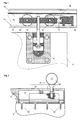
- the hardware system shown in Fig. 1, which meets these requirements, is in EP No. 96810171.7.
- the sliding element 2 is provided with a holder 3 ' via a connecting element 1 with a guided in a guide rail 10 on a tread 11 Drive 12 connected, the two drive wheels 14 and one for receiving the connecting element 1 in the drive body 13 provided thread 15.
- a stop 16 with an elastic buffer 17 is provided in the guide rail 10.
- the carriage 12 is held in the end stop by a retaining spring 18.
- This hardware system is stable and can be easily assembled.
- the sliding element 2 can after assembly of the Bracket 3 'can be easily hung on the connecting element 1.
- the connecting element 1 which can be screwed into the thread 15 of the drive 12
- the height of the sliding element 2 can be set as desired.
- the disadvantage of this fitting system is that the holder 3 ', which is inserted into a recess of the sliding element 2, easily from the outside visible and therefore hardly any, especially for sliding elements 2 provided in halls or living rooms is usable.
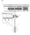
- the fitting system shown in FIG. 2 has a screw 19 on the sliding element 2 fastened holding rail 5 with a guidable therein and lockable by a holding screw 20 Holder 3 ", which is connected to a drive 12 'via a connecting element 1'.
- FIG. 6 it can be seen that the recess 4 provided in the top of the sliding element 2 used holding rail 5 covered by the front and back of the sliding element 2 and therefore is not visible from the user's point of view.
- a disadvantage of this known fitting system is that the bracket 3 "for adjusting the height of the sliding element 2 completely from the Retaining rail 5 extended, rotated one or more turns and reinserted got to.
- the drive 12 ' can be unhooked by lifting the sliding element 2 and be screwed further into the holder 3 ".
- the height adjustment of the sliding element 2 is the same Hardware system is therefore not easy to implement.
- the retaining screw 20 through which the bracket 3 " is locked again, difficult to access.
- the present invention is therefore based on the object of a fitting system for sliding To create elements that can be easily assembled.
- the fitting system according to the invention can be easily installed and adjusted.
- the necessary Settings are in a few simple steps and without lifting the sliding element or that The drive can be unmounted and can therefore be easily carried out by a single person become.
- Fig. 3 shows the inventive Fitting system, which is connected to a sliding element 2 by means of fastening screws 19 Has holding rail 5, into which a holder 3 is inserted, which via a connecting element 1 is connected to a drive 12 guided in a guide rail 10 on a running surface 11.
- the bracket 3 has two bevels 34 (see Fig. 4 and Fig. 6) against which one with the bracket 3 screwable wedge 7 can be guided such that the holder 3 can be locked in the holding rail 5 is.
- the wedge 7 is inserted and screwed in easily from the front side of the sliding element 2 (see FIG. 2, retaining screw 20).
- the holder 3 and preferably also the wedge 7 a guide groove 35 or 71 on both sides, into each of which a guide groove 6 of the U-shaped holding rail 5 protrudes.
- the wedge 3 is down and the bracket 3 pressed up, after which a non-positive connection between the guide groove 6 and the guide groove 35 is formed. As a result, the holder 3 is locked in the holding rail 5.
- Fig. 5 shows a preferred embodiment of the wedge 7, which has two wedge feet 72, between which Over a plate 77 connecting the wedge feet 72, a lag screw 39 is provided, which in a the holder 3 provided thread 32 can be screwed.
- the wedge 7 has a wedge guide on both sides 71, which runs under the guide groove 6 of the holding rail 5.
- the wedge 7 can therefore up to Bracket 3 are inserted, after which by a screw stop 73 and preferably two bendable retaining bracket 74 held lag screw 39 can be screwed to the bracket 3.
- the wedge 7 By pressing the tightened tension screw 39 against the screw stop 73, the wedge 7 pushed against the bracket 3.
- the wedge 7 has an opening 75.
- the inserted wedge 7, as shown in FIG. 3, is preferably connected to a cover 22 in such a way that that the end piece of the holding rail 5 or the end face 24 of the sliding element 2 is covered.
- a stop 21 is preferably provided in the holding rail 5, up to which the holder 3 in each case inserted and then wedged. This ensures that the position of the sliding element 2 is always set correctly relative to the stop 16. After the height adjustment of the Sliding element 2 therefore no longer has to be readjusted its end stop.
- a screw (21) was used, which protrudes into the holding rail 5.
- the stop 21 can also be provided permanently on the holding rail 5.
- connection element 1 fixed by a screw 38 which by a provided in the holder 3 thread 31 against the Connection element 1 is screwed.
- the connecting element 1 can also be fixed in the holder 3 held and released only for lifting by lifting the bracket 3. After lowering the connecting element 1 would be fixed again by the shoulder 37. After the height adjustment the holder 3 is pushed back into the holding rail 5 and as described above the wedge 7 locked.
- the installation of the holding rail 5 in the sliding element 2 can be seen from FIG. 6.
- the holding rail 5 is inserted from above or from the side into a recess 4, the dimensions of the holding rail 5 corresponds and by which the holding rail 5 is encompassed. From the front and the back of the sliding element 2, the fitting system is therefore not visible. From the side the remaining one Opening through the cover 22 completed.
Description
- Fig. 1
- ein bekanntes Beschlagsystem, das nach der Installation sichtbar ist,
- Fig. 2
- ein bekanntes Beschlagsystem, das nach der Installation nicht mehr sichtbar, jedoch nur mit erheblichen Aufwand einstellbar ist,
- Fig. 3
- eine erfindungsgemässe Befestigungsvorrichtung mit einer in einer Halteschiene durch einen Keil arretierbaren Halterung,
- Fig. 4
- die Halterung gemäss Fig. 3,
- Fig. 5
- der Keil gemäss Fig. 3,
- Fig. 6
- die Halteschiene gemäss Fig. 3 eingesetzt in ein verschiebbares Element und
- Fig. 7
- die aus der Halteschiene herausgezogene Halterung gemäss Fig. 3.
Claims (8)
- Beschlagsystem für ein an einer Ecke mit einer Ausnehmung (4) versehenes und von wenigstens einem Laufwerk (12) entlang einer Führungsschiene (10) geführtes Schiebelement (2), mit einer in die Ausnehmung (4) einfügbaren U-profil-förmigen Halteschiene (5), innerhalb der eine arretierbare, über ein Verbindungselement (1) mit dem Laufwerk (12) verbindbare Halterung (3) entlang zumindest annähemd parallel zur Führungsschiene (10) verlaufender Führungsrillen (6) der Halteschiene (5) verschiebbar gelagert ist, dadurch gekennzeichnet, dass die Halterung (3) wenigstens eine Abschrägung (34) aufweist, gegen die ein in der Halteschiene (5) geführter Keil (7) derart verschiebbar ist, dass die Halterung (3) an einer wählbaren Position in der Halteschiene (5) gegen die Führungsrillen (6) andrückbar und somit arretierbar ist und dass dazu der Keil (7) mit der Halterung (3) durch eine Schraube (39) verschraubbar ist, die parallel zur Halteschiene (5) verläuft.
- Beschlagsystem nach Anspruch 1, dadurch gekennzeichnet, dass die Halterung (3) und der Keil (7) in der Halteschiene (5) vorzugsweise durch dieselbe Führungsrille (6) führbar sind.
- Beschlagsystem nach Anspruch 1 oder 2, dadurch gekennzeichnet, dass in der Halteschiene (5) ein Anschlag (21) für die Halterung (3) vorgesehen ist.
- Beschlagsystem nach Anspruch 1, 2 oder 3, dadurch gekennzeichnet, dass der Keil (7) zwei Keilfüsse (72) aufweist, zwischen denen über einer die Keilfüsse (72) verbindenden Platte (77) eine in ein in der Halterung (3) vorgesehenes Gewinde (32) einschraubbare Zugschraube (39) einsetzbar ist, durch die der Keil (7) fest mit der Halterung (3) verbindbar ist.
- Beschlagsystem nach Anspruch 1, 2, 3 oder 4, dadurch gekennzeichnet, dass der Keil (7) verbiegbare Haltebügel (74) aufweist durch die die Zugschraube (39) im Keil (7) gehalten wird.
- Beschlagsystem nach Anspruch nach einem der Ansprüche 1 - 5, dadurch gekennzeichnet, dass der Keil (7) mit einer Abdeckung (22) derart verbindbar ist, dass das Endstück der Halteschiene (5) abdeckbar ist.
- Beschlagsystem nach einem der Ansprüche 1 - 6, dadurch gekennzeichnet, dass die Halterung (3) eine Bohrung (36) aufweist, durch die das Verbindungselement (1) derart einschiebbar ist, dass dessen Kopfstück (8) durch eine Schulter (37) in der Halterung (3) vorzugsweise drehbar gehalten wird.
- Beschlagsystem nach Anspruch 7, dadurch gekennzeichnet, dass das Verbindungselement (1) eine Schraube ist, die durch eine Schraube (38) arretierbar ist oder die nach dem Einsetzen in die Bohrung (36) durch die Schulter (37) fixiert wird.
Applications Claiming Priority (3)
| Application Number | Priority Date | Filing Date | Title |
|---|---|---|---|
| CH173496 | 1996-07-11 | ||
| CH173496 | 1996-07-11 | ||
| CH1734/96 | 1996-07-11 |
Publications (2)
| Publication Number | Publication Date |
|---|---|
| EP0818598A1 EP0818598A1 (de) | 1998-01-14 |
| EP0818598B1 true EP0818598B1 (de) | 1999-12-08 |
Family
ID=4217349
Family Applications (1)
| Application Number | Title | Priority Date | Filing Date |
|---|---|---|---|
| EP97810424A Expired - Lifetime EP0818598B1 (de) | 1996-07-11 | 1997-07-01 | Beschlagsystem für verschiebbare Elemente |
Country Status (4)
| Country | Link |
|---|---|
| EP (1) | EP0818598B1 (de) |
| AT (1) | ATE187524T1 (de) |
| DE (1) | DE59700817D1 (de) |
| ES (1) | ES2139430T3 (de) |
Cited By (1)
| Publication number | Priority date | Publication date | Assignee | Title |
|---|---|---|---|---|
| EP4144945A1 (de) | 2021-09-07 | 2023-03-08 | Hawa Sliding Solutions AG | Schiebetürsystem, schiebetür und puffervorrichtung |
Families Citing this family (11)
| Publication number | Priority date | Publication date | Assignee | Title |
|---|---|---|---|---|
| ES2273467T3 (es) * | 1998-03-05 | 2007-05-01 | Eku Ag | Herraje con roldanas para puertas de corredera. |
| PT943772E (pt) * | 1998-03-06 | 2005-06-30 | Klein Iberica | Estrutura de montagem de portas deslizantes |
| EP0982457B1 (de) * | 1998-08-21 | 2009-10-07 | Eku Ag | Laufwerks-Anordnung für eine Schiebetür |
| ES2220218B1 (es) * | 2003-05-23 | 2006-02-16 | Klein Iberica, S.A. | Mecanismo para suspension y regulacion de puertas plegables. |
| ES2564556T3 (es) * | 2006-10-19 | 2016-03-23 | Hawa Ag | Dispositivo con un mecanismo de rodadura para sujetar placas desplazables y elemento de separación |
| BE1018029A5 (nl) * | 2008-03-03 | 2010-04-06 | Louage En Wisselinck Nv | Schuifdeurinrichting. |
| CH702258A1 (de) * | 2009-11-26 | 2011-05-31 | Eku Ag | Laufwerk für eine Schiebetür. |
| CH705670A1 (de) * | 2011-10-27 | 2013-04-30 | Eku Ag | Befestigungsvorrichtung für eine Schiebetür an einem Laufwerkwagen. |
| EP2851496A1 (de) | 2013-09-18 | 2015-03-25 | Hawa Ag | Justierbare Montagevorrichtung für ein Schiebeelement sowie Schiebevorrichtung |
| AT518919B1 (de) * | 2016-08-01 | 2019-04-15 | Tif Gmbh | Beschlag für eine Schiebetüre |
| CN114348659A (zh) * | 2021-12-15 | 2022-04-15 | 安徽精菱玻璃机械有限公司 | 一种大型件输送用导向组件及大型件中转装置 |
Family Cites Families (4)
| Publication number | Priority date | Publication date | Assignee | Title |
|---|---|---|---|---|
| DE710243C (de) * | 1938-06-28 | 1941-09-08 | Dowaldwerke | Nachstellvorrichtung fuer Schiebetueren mittels einstellbarer Keile |
| DE888305C (de) * | 1951-10-12 | 1953-08-31 | Hugo Willach & Soehne | Schiebetuerbeschlag |
| CH430486A (de) * | 1965-12-01 | 1967-02-15 | Hawa Ag | Laufrollengehänge für Türen oder Fenster |
| US3996643A (en) * | 1975-09-08 | 1976-12-14 | Steigerwald Joseph F | Roller wheel assembly for sliding closure |
-
1997
- 1997-07-01 ES ES97810424T patent/ES2139430T3/es not_active Expired - Lifetime
- 1997-07-01 EP EP97810424A patent/EP0818598B1/de not_active Expired - Lifetime
- 1997-07-01 DE DE59700817T patent/DE59700817D1/de not_active Expired - Lifetime
- 1997-07-01 AT AT97810424T patent/ATE187524T1/de active
Cited By (1)
| Publication number | Priority date | Publication date | Assignee | Title |
|---|---|---|---|---|
| EP4144945A1 (de) | 2021-09-07 | 2023-03-08 | Hawa Sliding Solutions AG | Schiebetürsystem, schiebetür und puffervorrichtung |
Also Published As
| Publication number | Publication date |
|---|---|
| EP0818598A1 (de) | 1998-01-14 |
| ES2139430T3 (es) | 2000-02-01 |
| DE59700817D1 (de) | 2000-01-13 |
| ATE187524T1 (de) | 1999-12-15 |
Similar Documents
| Publication | Publication Date | Title |
|---|---|---|
| EP0267477B1 (de) | Befestigungsvorrichtung für einstellbare Frontblenden von Schubladen | |
| AT399087B (de) | Befestigungsbeschlag für schubladen-frontblenden | |
| EP0818598B1 (de) | Beschlagsystem für verschiebbare Elemente | |
| WO2000065186A1 (de) | Aufhängevorrichtung | |
| EP2222202A1 (de) | Frontverstellung für schubkästen und schubkasten | |
| DE202011101342U1 (de) | Scharnier | |
| AT512748A1 (de) | Einstellvorrichtung zum Einstellen einer Lage einer Schublade | |
| DE2458566C2 (de) | ||
| EP1764018A2 (de) | System zur Befestigung einer Platte | |
| EP0114903B1 (de) | Trennwand für Dusche mit wenigstens einer feststehenden Abtrennwand sowie mindestens einer Schiebetüre | |
| EP2255058A1 (de) | Profilsystem für einen aufsatz-rollladenkasten | |
| EP3695748B1 (de) | Einbauschrankanordnung | |
| DE102018001119B3 (de) | Halterung für Blumen und Dekorationswaren an Fenster- und Türflügeln | |
| EP0140114A2 (de) | Scharnier für einen Fenster- oder Türladen | |
| DE102010017628B3 (de) | Türband für die aufgesetzte Montage an Hohlkammersystemen | |
| DE102008006800B4 (de) | Führungsvorrichtung für einen Schiebeflügel | |
| DE3302454C1 (de) | Trennwand für Dusche mit wenigstens einer feststehenden Abtrennwand sowie mindestens einer Schiebetüre | |
| EP1114910B1 (de) | Rollladenkasten, insbesondere Vorsatzkasten | |
| DE102017203688B4 (de) | Rauchschalterzentrale | |
| DE3300735A1 (de) | Vorrichtung zum ausrichten einer tragvorrichtung, z.b. der schienenanordnung von schwebetueren eines schrankes | |
| EP1038486B1 (de) | Bausatz für Duschabtrennungen | |
| DE7535313U (de) | Schubkasten-fuehrungsschiene | |
| DE2934261A1 (de) | Wandaufhaengung fuer moebelteile | |
| EP2540942B1 (de) | Verstellbare Beschlagsanordnung | |
| DE202006016279U1 (de) | Führungselement für ein Bauelement |
Legal Events
| Date | Code | Title | Description |
|---|---|---|---|
| PUAI | Public reference made under article 153(3) epc to a published international application that has entered the european phase |
Free format text: ORIGINAL CODE: 0009012 |
|
| 17P | Request for examination filed |
Effective date: 19970725 |
|
| AK | Designated contracting states |
Kind code of ref document: A1 Designated state(s): AT CH DE ES FR IT LI |
|
| AKX | Designation fees paid |
Free format text: AT CH DE ES FR IT LI |
|
| RBV | Designated contracting states (corrected) |
Designated state(s): AT CH DE ES FR IT LI |
|
| 17Q | First examination report despatched |
Effective date: 19981223 |
|
| GRAG | Despatch of communication of intention to grant |
Free format text: ORIGINAL CODE: EPIDOS AGRA |
|
| GRAG | Despatch of communication of intention to grant |
Free format text: ORIGINAL CODE: EPIDOS AGRA |
|
| GRAH | Despatch of communication of intention to grant a patent |
Free format text: ORIGINAL CODE: EPIDOS IGRA |
|
| GRAH | Despatch of communication of intention to grant a patent |
Free format text: ORIGINAL CODE: EPIDOS IGRA |
|
| GRAA | (expected) grant |
Free format text: ORIGINAL CODE: 0009210 |
|
| ITF | It: translation for a ep patent filed |
Owner name: BARZANO' E ZANARDO MILANO S.P.A. |
|
| AK | Designated contracting states |
Kind code of ref document: B1 Designated state(s): AT CH DE ES FR IT LI |
|
| REF | Corresponds to: |
Ref document number: 187524 Country of ref document: AT Date of ref document: 19991215 Kind code of ref document: T |
|
| REG | Reference to a national code |
Ref country code: CH Ref legal event code: EP |
|
| REG | Reference to a national code |
Ref country code: CH Ref legal event code: NV Representative=s name: PATENTANWAELTE SCHAAD, BALASS, MENZL & PARTNER AG |
|
| REF | Corresponds to: |
Ref document number: 59700817 Country of ref document: DE Date of ref document: 20000113 |
|
| REG | Reference to a national code |
Ref country code: ES Ref legal event code: FG2A Ref document number: 2139430 Country of ref document: ES Kind code of ref document: T3 |
|
| ET | Fr: translation filed | ||
| REG | Reference to a national code |
Ref country code: CH Ref legal event code: NV Representative=s name: PETER RUTZ |
|
| PLBE | No opposition filed within time limit |
Free format text: ORIGINAL CODE: 0009261 |
|
| STAA | Information on the status of an ep patent application or granted ep patent |
Free format text: STATUS: NO OPPOSITION FILED WITHIN TIME LIMIT |
|
| 26N | No opposition filed | ||
| PGFP | Annual fee paid to national office [announced via postgrant information from national office to epo] |
Ref country code: CH Payment date: 20140721 Year of fee payment: 18 Ref country code: DE Payment date: 20140721 Year of fee payment: 18 |
|
| PGFP | Annual fee paid to national office [announced via postgrant information from national office to epo] |
Ref country code: ES Payment date: 20140728 Year of fee payment: 18 Ref country code: FR Payment date: 20140721 Year of fee payment: 18 Ref country code: AT Payment date: 20140611 Year of fee payment: 18 |
|
| PGFP | Annual fee paid to national office [announced via postgrant information from national office to epo] |
Ref country code: IT Payment date: 20140729 Year of fee payment: 18 |
|
| REG | Reference to a national code |
Ref country code: DE Ref legal event code: R119 Ref document number: 59700817 Country of ref document: DE |
|
| REG | Reference to a national code |
Ref country code: CH Ref legal event code: PL |
|
| REG | Reference to a national code |
Ref country code: AT Ref legal event code: MM01 Ref document number: 187524 Country of ref document: AT Kind code of ref document: T Effective date: 20150701 |
|
| PG25 | Lapsed in a contracting state [announced via postgrant information from national office to epo] |
Ref country code: IT Free format text: LAPSE BECAUSE OF NON-PAYMENT OF DUE FEES Effective date: 20150701 Ref country code: CH Free format text: LAPSE BECAUSE OF NON-PAYMENT OF DUE FEES Effective date: 20150731 Ref country code: LI Free format text: LAPSE BECAUSE OF NON-PAYMENT OF DUE FEES Effective date: 20150731 Ref country code: DE Free format text: LAPSE BECAUSE OF NON-PAYMENT OF DUE FEES Effective date: 20160202 |
|
| REG | Reference to a national code |
Ref country code: FR Ref legal event code: ST Effective date: 20160331 |
|
| PG25 | Lapsed in a contracting state [announced via postgrant information from national office to epo] |
Ref country code: FR Free format text: LAPSE BECAUSE OF NON-PAYMENT OF DUE FEES Effective date: 20150731 Ref country code: AT Free format text: LAPSE BECAUSE OF NON-PAYMENT OF DUE FEES Effective date: 20150701 |
|
| REG | Reference to a national code |
Ref country code: ES Ref legal event code: FD2A Effective date: 20160826 |
|
| PG25 | Lapsed in a contracting state [announced via postgrant information from national office to epo] |
Ref country code: ES Free format text: LAPSE BECAUSE OF NON-PAYMENT OF DUE FEES Effective date: 20150702 |