EP0817481A2 - Procédé de reproduction, appareil de reproduction et appareil d'enregistrement et de reproduction utilisant le même procédé de reproduction, et moyen d'enregistrement sur lequel le même procédé a été enregistré - Google Patents
Procédé de reproduction, appareil de reproduction et appareil d'enregistrement et de reproduction utilisant le même procédé de reproduction, et moyen d'enregistrement sur lequel le même procédé a été enregistré Download PDFInfo
- Publication number
- EP0817481A2 EP0817481A2 EP97304568A EP97304568A EP0817481A2 EP 0817481 A2 EP0817481 A2 EP 0817481A2 EP 97304568 A EP97304568 A EP 97304568A EP 97304568 A EP97304568 A EP 97304568A EP 0817481 A2 EP0817481 A2 EP 0817481A2
- Authority
- EP
- European Patent Office
- Prior art keywords
- error correction
- correction code
- data
- recording
- interleaving
- Prior art date
- Legal status (The legal status is an assumption and is not a legal conclusion. Google has not performed a legal analysis and makes no representation as to the accuracy of the status listed.)
- Granted
Links
Images


Classifications
-
- H—ELECTRICITY
- H04—ELECTRIC COMMUNICATION TECHNIQUE
- H04N—PICTORIAL COMMUNICATION, e.g. TELEVISION
- H04N5/00—Details of television systems
- H04N5/76—Television signal recording
- H04N5/91—Television signal processing therefor
- H04N5/93—Regeneration of the television signal or of selected parts thereof
- H04N5/94—Signal drop-out compensation
- H04N5/945—Signal drop-out compensation for signals recorded by pulse code modulation
Definitions
- the present invention relates to a technology for recording digital signals in plural tracks, by dividing one track in recording into plural blocks, extracting at least one block from one track, and reproducing the data from a recording medium in which data undergoing error correction code encoding by interleaving signals in plural block among plural tracks are recorded, and more particularly to this reproducing method, a reproducing apparatus using this method, a recording and reproducing apparatus combined with a recording apparatus, and a recording medium having the same method recorded therein.
- the reproducing method of the invention comprises a step of reproducing data from a track recording interleaved signals among plural tracks, a step of storing the reproduced data, a step of correcting error of the recorded data, a step of issuing an error correction disable signal at the time of data processing unable to correct error in this error correction process, and a step of controlling so as not to issue any of data in the tracks in the interleaving relation with the data with output of error correction disable signal. Consequently, only by adding the function for controlling the signal to be issued on the basis of the result of detection of error correction disable, although the reproduced image is a still picture in a worst case, the screen is not very objectionable due to error and noise, it is effective to reproduce stably.
- the step of correcting error of stored data includes a step of de-interleaving and a step of decoding an error correction code.
- the step of controlling so as not to issue any of data in the tracks in the interleaving relation with the data with output of error correction disable signal is a step of controlling so as not to issue only the signal in the block of the track containing the code word of correction disable.
- the reproducing apparatus and recording and reproducing apparatus of the invention comprise means for reproducing signals recorded in tracks by interleaving among plural tracks by dividing track data into plural blocks, mans of de-interleaving the reproduced signal, decoding means for decoding an error correction code by using data from the means for de-interleaving, correction disable display means for issuing a correction disable signal when error cannot be corrected by the decoding means, and output control means so as not to issue any of the signals of the tracks having interleaving relation with the data of output of correction disable signal by this correction disable display means.
- the means for de-interleaving the reproduced signal includes a memory for storing the reproduced signal. and memory control means for writing and reading in the memory according to interleaving pattern.
- the output controi means controls so as not to issue only the signal in the block of the track containing code word of correction disable.
- the recording medium of the invention records data necessary for execution of the above reproducing method, and by using this recording medium the reproducing apparatus, and recording and reproducing apparatus of the invention can be reaiized.
- Fig. 1 is a block diagram showing a constitution of a recording and reproducing apparatus according to embodiment 1 of the invention.
- Fig. 2 is a block diagram showing a constitution of a recording and reproducing apparatus according to embodiment 2 of the invention.
- Fig. 3 is a block diagram showing a constitution of a reproducing unit of a recording and reproducing apparatus according to embodiment 3 of the invention.
- Fig. 4 is a block diagram showing a constitution of a reproducing unit of a recording and reproducing apparatus according to embodiment 4 of the invention.
- Fig. 5 is a block diagram showing a constitution of a reproducing unit of a recording and reproducing apparatus according to modified embodiment 4 of the invention.
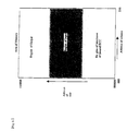
- Fig. 6 is a diagram showing a memory space in an embodiment of the invention.
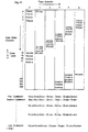
- Fig. 7 is a diagram showing a data layout example in an embodiment of the invention.
- Fig. 8 is a diagram showing an example of three-dimensional shuffling of interleaving pattern in an embodiment of the invention.
- Fig. 9 is a diagram showing an example of two-dimensional shuffling of interleaving pattern in an embodiment of the invention.
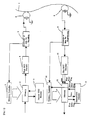
- Fig. 1 is a block diagram showing a constitution of a recording and reproducing apparatus in embodiment 1 of the invention.
- Fig. 6 is a diagram of a memory space
- Fig. 7 is an example of a store region of error flag
- Fig. 8 and Fig. 9 show examples of interleaving.
- reference numeral 1 is a memory controller
- 2 is a memory
- 3 is a second error correction code encoder
- 4 is a first error correction code encoder
- 5 is a converter of data for recording
- 6 is a recording head
- 7 is a recording medium
- 8 is a reproducing head
- 9 is a converter of data for reproducing
- 10 is a first error correction code decoder
- 11 is a memory controller
- 12 is a memory
- 13 is a second error correction decoder.
- the input signal is supposed to be a digital signal of MPEG2. It is also supposed to record data in plural tracks in a magnetic tape by helical scanning technique. First, the recording operation is described.
- a signal is transmitted from a satellite or the like, and the transmission format is decoded in a set-top box or the like, and is issued.
- the signal after processing the packet information of the output signal from the set-top box is fed into the memory 2.
- FIG. 6 An example of memory space of the memory 2 is shown in Fig. 6.
- the allotment of the memory region is not an important point, as a simplest case, it is supposed there is a region of three times of the interleaving region of the second error correction code.
- the bottom 1/3 region is supposed to be an operation region of second error correction code (ECC)
- ECC second error correction code
- the middle 1/3 region to be an input region
- the top 1/3 region to be an output region.
- the input data in the memory 2 is stored in the input region of the memory space in Fig. 6.
- the data from the memory 2 is sent out into the second error correction code encoder 3.
- interleaving patterns are shown in Fig. 8 and Fig. 9.
- the interleaving format at this time is shown in polynomial 1.
- t, s, d denote three directions of three-dimensional configuration of the data to be recorded as shown in Fig. 8, and specifically t indicates the track direction to be recorded, s is the sync block direction, and d is the direction of number of bytes.
- ⁇ mod6 means the "remainder when ⁇ is divided by 6.”
- the interleaving pattern is brief described below.
- the data to be recorded is arranged three-dimensionally.
- the so-called X-axis direction is named the byte direction
- the Z-axis direction is the sync block direction
- the Y-axis direction is the track direction.
- the data flow sequence is from the byte direction to the sync block direction and to the track direction.
- a second error correction code is generated.
- the number of tracks having interleaving relation is 6, the adjacent data within one code word decreases by one each in track number (however 0 is followed by 5), the sync block number increases by 3 each, and the byte number is constant. Accordingly, since the byte number is constant, omitting the byte direction, it is Fig. 9 that shows the two-dimensional interleave.
- Fig. 9 the same mark indicates the same code word. Since the two-dimensional interleave excluding the byte direction is same also in next byte number, a set of two-dimensional interleaves differing only in the byte number is a block of second error correction code. At this time, as known from the fact that there are 18 code words in the sync block direction s in Fig. 9, there are 18 second error correction code blocks in six tracks.
- the data extracted from the memory 2 is transmitted to the second error correction code encoder 3, and the parity data is calculated for generating the code word for minimum distance (d2 herein) so called in the technology of error correction code encoding.
- the parity data calculation is performed for example, according to polynomial 2.
- the operation symbol II means the operation for multiplying all elements.
- GF is Galois form in the error correction code encoding technology, and the primitive element indicates the element.
- the calculated parity data is written into the memory 2 according to polynomial 1 which is the same relation polynomial as above.
- 18 second error correction code blocks When 18 second error correction code blocks are completed, they are issued into the first error correction code encoder 4 through the memory 2. Control of data input and output from such memory 2 is effected by the memory controller 1.
- parity data for generating the code word of minimum distance d1 so called in the error correction code encoding technology is calculated.
- the parity data is calculated in polynomial 3, and sent out into the converter of data for recording 5 together with input data.
- d1 9.
- the input signal is converted into a signal suited to recording, and is sent out in to the recording head 6.
- a sync block is generated, and it is scrambled by M-length code, pre-code of partial response class 4 is processed, recording is equalized to achieve optimum recording so that the error rate may be smallest when reproducing, and the signal is sent into the recording head 6.
- the signal is then recorded into the recording medium 7 by the recording head 6.
- a magnetic tape is assumed, but, of course, magnetic disk, optical disk or other media may be used.
- the reproducing head 8 picks up a signal from the recording medium 7. At this time, the reproducing head 8 may be same as the recording head 6 or a different one.
- the signal picked up by the reproducing head 8 is properly processed in the converter of data for reproducing 9, and is issued into the first error correction code decoder 10.
- proper processing by the converter of data for reproducing 9 is, for example, conversion of reproduction signal into a multi-value digital signal in every clock, decoding into binary digital signal by using Viterbi decoder, descrambling by using M-length signal, detecting sync bit to determine sync block and decoding ID bit, and the data of obtained result is issued into the first error correction code decoder 10.
- the first error correction code decoder 10 the first error correction code is decoded according to the decoding method disclosed, for example, in the publication "Coding Theory” (Hideki Imai, Society of Electronic Information and Communication), and the data is issued to the memory 12. If failing to correct in the first error correction code decoder 10, a first error flag is issued to the memory 12.
- the memory 12 may be same as the memory 2, or a different one.
- the data from the memory 12 is issued to the second error correction code decoder 13 according to polynomial 1 which is the interleaving polynomial, and the first error flag corresponding to individual data is issued to the second error correction code decoder 13.
- the second error correction code decoder 13 while using the first error flag, the second error correction code is decoded according to the decoding method disclosed in the publication "Coding Theory," and the decoded data is put into the memory 12.
- a second error flag is issued to the memory controller 11. This second error flag corresponds to the correction disable signal in claim 1 of the invention, which transmits the information that could not be corrected of error.
- the memory controller 11 controls the input and output operation of data in the memory 12, and when receiving a second error flag from the second error correction code decoder 13, it controls so as not to issue data for the portion of six tracks having interleaving relation by the six-track pulse from the converter of data for reproducing 9. In this way, only the data of the track not issuing second error flag in the second error correction code decoder 13 is issued from the memory 12.
- the memory controller 11 contains the function of the memory controller 1, they may be shared commonly. Also the memory 2 and memory 12 may be commonly shared. An example of store region of error flag and store region of other data is shown in Fig. 7.
- reproduced data is stored in the memory, and output data is selected and issued by reproduction disable signal (error flag), but the same effect is obtained by data control without using memory.
- the memory controller 11 may control so as not to issue the code block of the second error correction code related with the second error flag. In this case, too, the same effects as above are obtained.
- the invention also includes as an embodiment the reproducing apparatus for reproducing only, excluding the recording apparatus portion (the portion composed of memory controller 1, memory 2, second error correction code encoder 3, first error correction code encoder 4, converter of data for recording 5, and recording head 6) from thus constituted recording and reproducing apparatus.
- the recording apparatus portion the portion composed of memory controller 1, memory 2, second error correction code encoder 3, first error correction code encoder 4, converter of data for recording 5, and recording head 6) from thus constituted recording and reproducing apparatus.
- FIG. 2 is a block diagram showing the constitution of the recording and reproducing apparatus of embodiment 2 of the invention. What embodiment 2 differs from embodiment 1 lies in the output of error flag from the first error correction code decoder 10 and the operation of the memory controller 11, memory 12, and second error correction code decoder 13.
- reference numeral 1 is a memory controller
- 2 is a memory
- 3 is a second error correction code encoder
- 4 is a first error correction code encoder
- 5 is a converter of data for recording
- 6 is a recording head
- 7 is a recording medium
- 8 is a reproducing head
- 9 is a converter of data for reproducing
- 10 is a first error correction code decoder
- 11 is a memory controller
- 12 is a memory
- 13 is a second error correction decoder.
- the recording process and the operation up to the output from the converter of data for reproducing 9 are same as in embodiment 1, and are omitted herein, and only the operation of the first error correction code decoder 10, memory controller 11, memory 12, and second error correction code decoder 13 is described below.
- the first error correction code decoder 10 if correction disable occurs in any code word in the first error correction code, a first error flag is issued to the memory 12. Supposing the maximum integer not exceeding d1/2 which is half of the minimum distance d1 so called in the error correction code encoding technology to be t, if t code words of the error correction code are corrected in the first error correction code decoder 10, a second error flag is issued.
- the first error flag and second error flag are both stored in the memory 12 together with the data. According to polynomial 1 which is the interleaving polynomial, data is issued from the memory 12 into the second error correction code decoder 13.
- the operation of the second error correction decoder 1 3 and the operation of the memory controller 11 in the case of successful correction in the second error correction code decoder 13 are same as in the case of embodiment 1, and the explanation is omitted herein.
- an error flag to be issued to the memory controller 11 if a correction disable code word occurs in the second error correction code decoder 13 is called a third error flag.
- the error correction disable signal in the claim of the invention corresponds to this third error flag.
- the memory controller 11 When the memory controller 11 receives a third error flag from the second error correction code decoder 13, the memory controller 11 controls so as not to issue the code word of the first error correction code carrying the first error flag and second error flag, being the code word of the first error correction code, in the second error correction code block containing the code word of second error correction code being not corrected, out of the memory 12.
- control of preventing correction disabled signal from being issued as far as possible is realized in a very small circuit scale, and the noise appearing on the screen can be reduced, marked disturbance of reproduction screen can be prevented, and hence the picture quality can be enhanced.
- the invention also includes as an embodiment the reproducing apparatus for reproducing only, excluding the recording apparatus portion (the portion composed of memory controller 1, memory 2, second error correction code encoder 3, first error correction code encoder 4, converter of data for recording 5, and recording head 6) from thus constituted recording and reproducing apparatus.
- the recording apparatus portion the portion composed of memory controller 1, memory 2, second error correction code encoder 3, first error correction code encoder 4, converter of data for recording 5, and recording head 6) from thus constituted recording and reproducing apparatus.
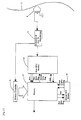
- FIG. 3 is a block diagram showing the constitution of the reproducing apparatus portion of the recording and reproducing apparatus of embodiment 3 of the invention. What embodiment 3 differs from embodiments 1 and 2 lies in the output of error flag from the first error correction code decoder 10 and the operation of the memory controller 11, memory 12, and second error correction code decoder 13.
- reference numeral 7 is a recording medium
- 8 is a reproducing head
- 9 is a converter of data for reproducing
- 10 is a first error correction code decoder
- 11 is a memory controller
- 12 is a memory
- 13 is a second error correction decoder.
- the recording process and the operation up to the output from the converter of data for reproducing 9 are same as in embodiment 1, and are omitted herein, and only the operation of the first error correction code decoder 10, memory controller 11, memory 12, and second error correction code decoder 13 is described below.
- the signal reproduced by the converter of data for reproducing 9 is fed into the first error correction code decoder 10.
- the first error correction code decoder 10 the first error correction code is decoded.
- the decoding method at this time may be same as described above. Also the manner of adding the first error flag in the case of correction disable may be same as above. However, the first parity symbol is also written into the memory 12.
- the data in the memory 12 is issued into the second error correction code decoder 13 according to polynomial 1 which is the interleaving polynomial.
- the first error flag is also issued into the second error correction code decoder 13.
- the operation of the second error correction code decoder 13 is same as above, but the second error correction code in the portion of the first parity symbol is also decoded. In the event of correction disable, a second error flag is issued to the memory 12.
- the corrected data being fed into the memory 12 is issued again into the first error correction code decoder 10 in the sync block unit.
- a second error flag is issued.
- the first error correction code decoder 10 by the decoding method using the second error flag, for example, by erasure correction, the first error correction code is decoded.
- a first error flag is set up again in the sync block that cannot be corrected. That is, if the first error flag is already set up, it is left as it is, and if not, it is set up. To the contrary, when corrected successfully, the first error flag is removed. Together with the first error flag, the signal is stored in the memory 12.
- the sync block not carrying first error flag is issued from the memory 12.
- Such input and output control of the memory 12 is carried out by the memory controller 11.
- the first error correction code decoder 10 corresponds to "a third error correction code decoder for further decoding the first error correction code in the sync block of which second error correction code is decoded, so as not to issue the data relating to correction disable in the case of correction disable" in claim 16. That is, as set forth in claim 17, the first error correction code decoder 10 shares the third error correction code decoder, and in this case, as compared with the one not sharing, the operating speed of the first error correction code decoder 10 is two times higher. Meanwhile, the third error correction code decoder may be realized by the generator of syndrome of first error correction code 14 described in embodiment 4.
- the first error correction code decoder 10 serving aiso as the third error correction code decoder sets up the first error flag again in the correction disable sync block in the second operation for decoding the first error correction code. That is, if the first error flag is already set up, it is left as it is, and if not, it is set up. To the contrary, when corrected successfully, the first error ilag is removed. Together with the first error flag, the data is stored in the memory 12. The sync block not carrying first error flag is issued from the memory 12, and therefore both the function of processing so as to correct error securely and the function of preventing output of error correction disable signal are provided, so that the picture quality may be further enhanced.
- the invention also includes as an embodiment the reproducing apparatus for reproduction only, excluding the recording apparatus portion not shown from thus constituted recording and reproducing apparatus.
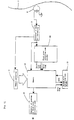
- FIG. 4 is a block diagram showing the constitution of the reproducing apparatus portion of the recording and reproducing apparatus of embodiment 4 of the invention. What embodiment 4 differs from embodiments 1, 2 and 3 lies in the constitution of a generator of syndrome of first error correction code 14 as third error correction code decoder, the output of error flag from the first error correction code decoder 10 and the opera- tion of the memory controller 11, memory 12, and second error correction code decoder 13.
- reference numeral 7 is a recording medium
- 8 is a reproducing head
- 9 is a converter of data for reproducing
- 10 is a first error correction code decoder
- 11 is a memory controller
- 12 is a memory
- 13 is a second error correction decoder
- 14 is a generator of syndrome of first error correction code.
- the signal reproduced by the converter of data for reproducing 9 is fed into the first error correction code decoder 10.
- the first error correction code decoder 10 the first error correction code is decoded.
- the decoding method at this time may be same as described above. Also the manner of adding the first error flag in the case of correction disable may be same as above. However, the first parity symbol is also written into the memory 12.
- the data in the memory 12 is issued into the second error correction code decoder 13 according to polynomial 1 which is the interleaving polynomial.
- the first error flag is also issued into the second error correction code decoder 13.
- the operation of the first error correction code decoder 13 is same as above, but the second error correction code in the portion of the first parity symbol is also decoded. In the event of correction disable, a second error flag is issued to the memory 12.
- the corrected data being fed into the memory 12 is issued again into the generator of syndrome of first error correction code 14 in the sync block unit.
- Such input and output control of the memory 12 is carried out by the memory controller 11.
- the syndrome of the first error correction code is calculated, and only the sync block judged to be free from error is issued. while sync block of which syndrome is not completely 0 is not issued.
- first error correction code decoder of nearly same constitution as the first error correction code decoder 10 may be separately prepared, and not only the data from the memory 12 but also the second error flag may be fed, and by the decoding method using the second error flag, for example, by erasure correction, the first error correction code may be decoded, and the corrected sync block may be issued, while uncorrected sync block may be prevented from being issued.
- Fig. 5 is a block diagram of performing error correction (ECC) of first error correction code in embodiment 4, by exclusive- OR, using the memory 12, of error data from the converter of data for reproducing 9 and correction data from the first error correction code decoder 10.
- ECC error correction
- the generator of syndrome of first error correction code 14 corresponds to "a third error correction code decoder for further decoding the first error correction code in the sync block of which second error correction code is decoded, so as not to issue the data relating to correction disable in the case of correction disable" of claim 16.
- control to prevent correction disable signal from being issued can be realized in a very small circuit scale, and noise appearing on the screen can be reduced, and the picture quality can be enhanced.
- the invention also includes as an embodiment the reproducing apparatus for reproduction only, excluding the recording apparatus portion not shown from the recording and reproducing apparatus constituted as shown in Fig. 4 or Fig. 5.
- the reproduced image may be a still picture in a worst case, but control for preventing correction disable signal from being reproduced as far as possible is realized automatically, and a largely disturbed screen due to error is not reproduced, the reby realizing the reproducing method, reproducing apparatus, and recording and reproducing apparatus capable of reproducing stably in a small circuit scale.
Landscapes
- Engineering & Computer Science (AREA)
- Multimedia (AREA)
- Signal Processing (AREA)
- Signal Processing For Digital Recording And Reproducing (AREA)
- Error Detection And Correction (AREA)
- Television Signal Processing For Recording (AREA)
Applications Claiming Priority (2)
| Application Number | Priority Date | Filing Date | Title |
|---|---|---|---|
| JP17361096A JP3362146B2 (ja) | 1996-07-03 | 1996-07-03 | 再生装置および記録再生装置 |
| JP173610/96 | 1996-07-03 |
Publications (3)
| Publication Number | Publication Date |
|---|---|
| EP0817481A2 true EP0817481A2 (fr) | 1998-01-07 |
| EP0817481A3 EP0817481A3 (fr) | 1999-05-19 |
| EP0817481B1 EP0817481B1 (fr) | 2008-03-05 |
Family
ID=15963806
Family Applications (1)
| Application Number | Title | Priority Date | Filing Date |
|---|---|---|---|
| EP97304568A Expired - Lifetime EP0817481B1 (fr) | 1996-07-03 | 1997-06-26 | Appareil de reproduction et appareil d'enregistrement et de reproduction |
Country Status (5)
| Country | Link |
|---|---|
| US (1) | US6047398A (fr) |
| EP (1) | EP0817481B1 (fr) |
| JP (1) | JP3362146B2 (fr) |
| CN (1) | CN1105387C (fr) |
| DE (1) | DE69738544T2 (fr) |
Cited By (1)
| Publication number | Priority date | Publication date | Assignee | Title |
|---|---|---|---|---|
| US7376888B2 (en) | 2004-10-19 | 2008-05-20 | International Business Machines Corporation | Interleaved recording of separated error correction encoded information |
Families Citing this family (7)
| Publication number | Priority date | Publication date | Assignee | Title |
|---|---|---|---|---|
| JP3834985B2 (ja) * | 1998-01-30 | 2006-10-18 | 三菱電機株式会社 | 記録データ制御装置 |
| US6668349B1 (en) * | 2000-04-14 | 2003-12-23 | Hitachi, Ltd. | Data recording/readback method and data recording/readback device for the same |
| JP3993035B2 (ja) * | 2001-07-19 | 2007-10-17 | 松下電器産業株式会社 | データ記録方法、記録媒体、および再生装置 |
| US7649829B2 (en) * | 2001-10-12 | 2010-01-19 | Qualcomm Incorporated | Method and system for reduction of decoding complexity in a communication system |
| AU2003202530A1 (en) * | 2002-04-01 | 2003-10-16 | Sony Corporation | Reproducing method, reproducing apparatus, recording method, and recording apparatus |
| US20060218468A1 (en) * | 2005-03-09 | 2006-09-28 | Matsushita Electric Industrial Co., Ltd. | Memory initialization device, memory initialization method, and error correction device |
| US10122384B2 (en) * | 2016-05-18 | 2018-11-06 | Arm Limited | Logical interleaver |
Citations (4)
| Publication number | Priority date | Publication date | Assignee | Title |
|---|---|---|---|---|
| US4277807A (en) * | 1976-12-24 | 1981-07-07 | Independent Broadcasting Authority | Recording digital signals |
| EP0267029A1 (fr) * | 1986-11-05 | 1988-05-11 | Sony Corporation | Procédé et appareil pour enregistrer et/ou reproduire des données digitales |
| EP0481752A1 (fr) * | 1990-10-17 | 1992-04-22 | Canon Kabushiki Kaisha | Codeur et décodeur de codes à correction d'erreurs |
| EP0596826A2 (fr) * | 1992-11-06 | 1994-05-11 | GOLDSTAR CO. Ltd. | Méthode de melange pour un magnétoscope à bande pour signaux vidéo numériques |
Family Cites Families (10)
| Publication number | Priority date | Publication date | Assignee | Title |
|---|---|---|---|---|
| DE3211053A1 (de) * | 1981-03-25 | 1982-10-14 | Akai Electric Co. Ltd. | Fehlerkorrektur- und kontrollsystem fuer pcm-dekodiergeraete |
| EP0203773B1 (fr) * | 1985-05-21 | 1992-07-15 | Sony Corporation | Appareil de décodage d'un code de correction d'erreurs |
| JP3158370B2 (ja) * | 1991-07-12 | 2001-04-23 | ソニー株式会社 | ディスクデータ再生装置 |
| US5373511A (en) * | 1992-05-04 | 1994-12-13 | Motorola, Inc. | Method for decoding a reed solomon encoded signal with inner code and apparatus for doing same |
| JP3455997B2 (ja) * | 1993-11-25 | 2003-10-14 | ソニー株式会社 | データ処理装置 |
| KR100258921B1 (ko) * | 1994-03-31 | 2000-06-15 | 윤종용 | 광디스크 기록/재생장치 |
| JP3322998B2 (ja) * | 1994-04-12 | 2002-09-09 | 三菱電機株式会社 | ディジタルvtr |
| JP3328093B2 (ja) * | 1994-07-12 | 2002-09-24 | 三菱電機株式会社 | エラー訂正装置 |
| JP3304643B2 (ja) * | 1994-10-14 | 2002-07-22 | ソニー株式会社 | 再生装置 |
| GB2295946B (en) * | 1994-12-01 | 1999-09-29 | Mitsubishi Electric Corp | Digital signal recording device,digital signal playback device,and digital signal decoding device therefor |
-
1996
- 1996-07-03 JP JP17361096A patent/JP3362146B2/ja not_active Expired - Fee Related
-
1997
- 1997-06-26 DE DE69738544T patent/DE69738544T2/de not_active Expired - Fee Related
- 1997-06-26 EP EP97304568A patent/EP0817481B1/fr not_active Expired - Lifetime
- 1997-07-02 CN CN97113732A patent/CN1105387C/zh not_active Expired - Fee Related
- 1997-07-02 US US08/886,867 patent/US6047398A/en not_active Expired - Fee Related
Patent Citations (4)
| Publication number | Priority date | Publication date | Assignee | Title |
|---|---|---|---|---|
| US4277807A (en) * | 1976-12-24 | 1981-07-07 | Independent Broadcasting Authority | Recording digital signals |
| EP0267029A1 (fr) * | 1986-11-05 | 1988-05-11 | Sony Corporation | Procédé et appareil pour enregistrer et/ou reproduire des données digitales |
| EP0481752A1 (fr) * | 1990-10-17 | 1992-04-22 | Canon Kabushiki Kaisha | Codeur et décodeur de codes à correction d'erreurs |
| EP0596826A2 (fr) * | 1992-11-06 | 1994-05-11 | GOLDSTAR CO. Ltd. | Méthode de melange pour un magnétoscope à bande pour signaux vidéo numériques |
Cited By (1)
| Publication number | Priority date | Publication date | Assignee | Title |
|---|---|---|---|---|
| US7376888B2 (en) | 2004-10-19 | 2008-05-20 | International Business Machines Corporation | Interleaved recording of separated error correction encoded information |
Also Published As
| Publication number | Publication date |
|---|---|
| JPH1021655A (ja) | 1998-01-23 |
| CN1105387C (zh) | 2003-04-09 |
| JP3362146B2 (ja) | 2003-01-07 |
| EP0817481B1 (fr) | 2008-03-05 |
| DE69738544T2 (de) | 2008-06-19 |
| CN1193165A (zh) | 1998-09-16 |
| EP0817481A3 (fr) | 1999-05-19 |
| US6047398A (en) | 2000-04-04 |
| DE69738544D1 (de) | 2008-04-17 |
Similar Documents
| Publication | Publication Date | Title |
|---|---|---|
| US5113293A (en) | Magnetic recorder/reproducer | |
| KR920000164B1 (ko) | 에러 정정 방법 및 장치 | |
| US4393502A (en) | Method and apparatus for communicating digital information words by error-correction encoding | |
| KR100250590B1 (ko) | 인코딩/디코딩 회로 및 디지탈 비디오 시스템 | |
| EP1053548B1 (fr) | Dispositif et procede permettant d'enregistrer un signal d'information numerique avec informations de trucage sur les pistes helicoidales d'un support d'enregistrement | |
| EP0481752B1 (fr) | Codeur et décodeur de codes à correction d'erreurs | |
| JPH0520105A (ja) | デジタルデータのエラー訂正装置 | |
| EP0817481A2 (fr) | Procédé de reproduction, appareil de reproduction et appareil d'enregistrement et de reproduction utilisant le même procédé de reproduction, et moyen d'enregistrement sur lequel le même procédé a été enregistré | |
| US4491882A (en) | Disc players | |
| US6085348A (en) | Error correction code encoder and decoder | |
| JP4140344B2 (ja) | 復号化装置及びコンピュータプログラム | |
| JP4126795B2 (ja) | 疑似積符号復号装置及び方法 | |
| US5796755A (en) | Error minimization in interleaved error correcting codes | |
| US6334024B1 (en) | Helical scan data recording apparatus and a helical scan data reproducing apparatus | |
| KR100196927B1 (ko) | 디지털 영상신호 기록/재생장치의 오류정정방법 | |
| JP3259359B2 (ja) | データ再生装置及び方法 | |
| JP2656915B2 (ja) | エラー訂正装置 | |
| JPH08509351A (ja) | セミサイクリックコードに基づく誤り補正可能データ伝送方法及び装置 | |
| JPH0628343B2 (ja) | 積符号の復号方法 | |
| JP3740256B2 (ja) | 誤り訂正符号復号化装置及び誤り訂正符号復号化方法 | |
| KR200151025Y1 (ko) | 디지탈 영상기록재생장치 | |
| JPH0574146B2 (fr) | ||
| JP2724632B2 (ja) | 多トラックデジタルテープレコーダ | |
| JPH0783275B2 (ja) | エラ−訂正符号の復号装置 | |
| JPS592214A (ja) | デイジタル記録・再生装置 |
Legal Events
| Date | Code | Title | Description |
|---|---|---|---|
| PUAI | Public reference made under article 153(3) epc to a published international application that has entered the european phase |
Free format text: ORIGINAL CODE: 0009012 |
|
| AK | Designated contracting states |
Kind code of ref document: A2 Designated state(s): DE FR GB |
|
| PUAL | Search report despatched |
Free format text: ORIGINAL CODE: 0009013 |
|
| AK | Designated contracting states |
Kind code of ref document: A3 Designated state(s): AT BE CH DE DK ES FI FR GB GR IE IT LI LU MC NL PT SE |
|
| 17P | Request for examination filed |
Effective date: 19990806 |
|
| AKX | Designation fees paid |
Free format text: DE FR GB |
|
| 17Q | First examination report despatched |
Effective date: 20030926 |
|
| 17Q | First examination report despatched |
Effective date: 20030926 |
|
| 17Q | First examination report despatched |
Effective date: 20030926 |
|
| GRAP | Despatch of communication of intention to grant a patent |
Free format text: ORIGINAL CODE: EPIDOSNIGR1 |
|
| RIC1 | Information provided on ipc code assigned before grant |
Ipc: G11B 20/18 20060101AFI20070612BHEP |
|
| RTI1 | Title (correction) |
Free format text: REPRODUCING APPARATUS AND RECORDING AND REPRODUCING APPARATUS |
|
| GRAS | Grant fee paid |
Free format text: ORIGINAL CODE: EPIDOSNIGR3 |
|
| GRAA | (expected) grant |
Free format text: ORIGINAL CODE: 0009210 |
|
| AK | Designated contracting states |
Kind code of ref document: B1 Designated state(s): DE FR GB |
|
| REG | Reference to a national code |
Ref country code: GB Ref legal event code: FG4D |
|
| REF | Corresponds to: |
Ref document number: 69738544 Country of ref document: DE Date of ref document: 20080417 Kind code of ref document: P |
|
| PGFP | Annual fee paid to national office [announced via postgrant information from national office to epo] |
Ref country code: DE Payment date: 20080703 Year of fee payment: 12 |
|
| RAP2 | Party data changed (patent owner data changed or rights of a patent transferred) |
Owner name: PANASONIC CORPORATION |
|
| PGFP | Annual fee paid to national office [announced via postgrant information from national office to epo] |
Ref country code: FR Payment date: 20080617 Year of fee payment: 12 |
|
| ET | Fr: translation filed | ||
| PGFP | Annual fee paid to national office [announced via postgrant information from national office to epo] |
Ref country code: GB Payment date: 20080702 Year of fee payment: 12 |
|
| PLBE | No opposition filed within time limit |
Free format text: ORIGINAL CODE: 0009261 |
|
| STAA | Information on the status of an ep patent application or granted ep patent |
Free format text: STATUS: NO OPPOSITION FILED WITHIN TIME LIMIT |
|
| 26N | No opposition filed |
Effective date: 20081208 |
|
| GBPC | Gb: european patent ceased through non-payment of renewal fee |
Effective date: 20090626 |
|
| REG | Reference to a national code |
Ref country code: FR Ref legal event code: ST Effective date: 20100226 |
|
| PG25 | Lapsed in a contracting state [announced via postgrant information from national office to epo] |
Ref country code: FR Free format text: LAPSE BECAUSE OF NON-PAYMENT OF DUE FEES Effective date: 20090630 |
|
| PG25 | Lapsed in a contracting state [announced via postgrant information from national office to epo] |
Ref country code: GB Free format text: LAPSE BECAUSE OF NON-PAYMENT OF DUE FEES Effective date: 20090626 |
|
| PG25 | Lapsed in a contracting state [announced via postgrant information from national office to epo] |
Ref country code: DE Free format text: LAPSE BECAUSE OF NON-PAYMENT OF DUE FEES Effective date: 20100101 |