EP0816657B1 - Verfahren und Vorrichtung zur Steuerung der Stromversorgung eines Heizers in einer Sauerstoffmesssonde - Google Patents
Verfahren und Vorrichtung zur Steuerung der Stromversorgung eines Heizers in einer Sauerstoffmesssonde Download PDFInfo
- Publication number
- EP0816657B1 EP0816657B1 EP97110383A EP97110383A EP0816657B1 EP 0816657 B1 EP0816657 B1 EP 0816657B1 EP 97110383 A EP97110383 A EP 97110383A EP 97110383 A EP97110383 A EP 97110383A EP 0816657 B1 EP0816657 B1 EP 0816657B1
- Authority
- EP
- European Patent Office
- Prior art keywords
- heater
- heaters
- cpu
- signal
- energizer
- Prior art date
- Legal status (The legal status is an assumption and is not a legal conclusion. Google has not performed a legal analysis and makes no representation as to the accuracy of the status listed.)
- Expired - Lifetime
Links
Images



Classifications
-
- F—MECHANICAL ENGINEERING; LIGHTING; HEATING; WEAPONS; BLASTING
- F02—COMBUSTION ENGINES; HOT-GAS OR COMBUSTION-PRODUCT ENGINE PLANTS
- F02D—CONTROLLING COMBUSTION ENGINES
- F02D41/00—Electrical control of supply of combustible mixture or its constituents
- F02D41/02—Circuit arrangements for generating control signals
- F02D41/14—Introducing closed-loop corrections
- F02D41/1438—Introducing closed-loop corrections using means for determining characteristics of the combustion gases; Sensors therefor
- F02D41/1439—Introducing closed-loop corrections using means for determining characteristics of the combustion gases; Sensors therefor characterised by the position of the sensor
- F02D41/1441—Plural sensors
- F02D41/1443—Plural sensors with one sensor per cylinder or group of cylinders
-
- F—MECHANICAL ENGINEERING; LIGHTING; HEATING; WEAPONS; BLASTING
- F02—COMBUSTION ENGINES; HOT-GAS OR COMBUSTION-PRODUCT ENGINE PLANTS
- F02D—CONTROLLING COMBUSTION ENGINES
- F02D41/00—Electrical control of supply of combustible mixture or its constituents
- F02D41/02—Circuit arrangements for generating control signals
- F02D41/14—Introducing closed-loop corrections
- F02D41/1438—Introducing closed-loop corrections using means for determining characteristics of the combustion gases; Sensors therefor
- F02D41/1493—Details
- F02D41/1494—Control of sensor heater
Definitions
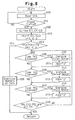
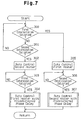
- a current controlling process in a gasoline engine system performed by the CPU 47 will be explained with reference to flowcharts of Figs. 4 and 5.
- the CPU 47 controls the current supply to the heaters 37a to 37c.
- step 100 the CPU 47 simultaneously starts energizing the first to third heaters 37a to 37c. This causes the heaters 37a to 37c to produce heat thereby warming the first to third elements 36a to 36c, respectively.
- step 200 the CPU 47 inputs the starter signal STA from the starter switch 43.
- step 201 the CPU 47 judges whether starting of the engine 11 has been completed. Specifically, the CPU 47 determines that the starting of the engine 11 is completed when the starter signal STA has changed from ON to OFF. If the determination is not satisfied in step 201, that is, if the engine 11 is still being cranked, the CPU 47 repeats the processes of steps 200, 201. If the determination is satisfied in step 201, the CPU 47 moves to step 202.
- step 204 If the determination is not satisfied in step 204, the CPU 47 moves to step 205. If the determination is satisfied in step 204 on the other hand, the CPU 47 moves to step 209.
- the determination in step 206 is satisfied.
- the CPU 47 thus starts energizing the second heater 37b and sets the second energizing flag FB2 to "1". Upon the start of energization of the second heater 37b, a rush current is supplied to the second heater 37b.
Landscapes
- Engineering & Computer Science (AREA)
- Chemical & Material Sciences (AREA)
- Combustion & Propulsion (AREA)
- Mechanical Engineering (AREA)
- General Engineering & Computer Science (AREA)
- Measuring Oxygen Concentration In Cells (AREA)
- Electrical Control Of Air Or Fuel Supplied To Internal-Combustion Engine (AREA)
- Combined Controls Of Internal Combustion Engines (AREA)
Claims (12)
- Vorrichtung zur Steuerung der Stromversorgung einer Vielzahl von zur Ermittlung des Luft-Brennstoffverhältnisses in einer Brennkraftmaschine dienenden Sonden (31 bis 33), wobei die Brennkraftmaschine einen Abgaskanal (19L, 19R, 26L, 26R, 27) aufweist, in dem die Sonden (31 bis 33) angeordnet sind, und jede Sonde (31 bis 33) ein Sensorelement (36a bis 36c) zur Erzeugung eines der Sauerstoffkonzentration des Abgases der Brennkraftmaschine entsprechenden Signals und eine Heizeinrichtung (37a bis 37c) zur Erwärmung des Sensorelements (36a bis 36c) aufweist, wobei jedes Sensorelement (36a bis 36c) bei Erreichen einer vorgegebenen Temperatur aktiviert wird und jede Heizeinrichtung (37a bis 37c) einen anfänglich hohen und sodann zeitabhängig abfallenden Laststrom aufweist, und wobei eine Stromversorgungseinrichtung (47) zur Erregung der Heizeinrichtungen (37a bis 37c) vorgesehen ist, die die Erregung einer jeden Heizeinrichtung (37a bis 37c) zur Verringerung des gesamten Laststroms der Heizeinrichtungen (37a bis 37c) zu einer jeweils unterschiedlichen Zeit einleitet,
dadurch gekennzeichnet, dass
für jedes Sensorelement (36a bis 36c) eine vorgegebene Heizzeitdauer vorgesehen ist, während der es auf die vorgegebene Temperatur aufgeheizt wird, und
die Stromversorgungseinrichtung (47) die Reihenfolge der Heizzeitperioden von der längsten zur kürzesten Zeitperiode festlegt und zuerst die Heizeinrichtung (37a bis 37c) erregt, die dem Sensorelement (36a bis 36c) mit der längsten Heizzeitperiode zugeordnet ist, während sie sodann die anderen Heizeinrichtungen (37a bis 37c) in der Reihenfolge abnehmender Heizzeitperioden erregt. - Vorrichtung nach Anspruch 1, mit einem Zeitgeber (47) zur Messung der Zeitdauer, die jedes Sensorelement (36a bis 36c) bis zum Erreichen der vorgegebenen Temperatur benötigt, wobei die Stromversorgungseinrichtung (47) die Stromversorgung auf der Basis der gemessenen Zeitdauer beginnt.
- Vorrichtung nach Anspruch 1 oder 2, bei der die Stromversorgungseinrichtung (47) das Verstreichen eines vorgegebenen minimalen Zeitintervalls von dem Zeitpunkt des Beginns der Erregung einer Heizeinrichtung (37a bis 37c) bis zu dem Zeitpunkt des Beginns der Erregung der nächsten Heizeinrichtung (37a bis 37c) abwartet.
- Vorrichtung nach Anspruch 1, bei der die Stromversorgungseinrichtung (47) einer jeden Heizeinrichtung (37a bis 37c) ein ein EIN-Signal und ein AUS-Signal umfassendes Impulssignal zuführt und das einer jeden Heizeinrichtung (37a bis 37c) zugeführte Impulssignal zur Verringerung des gesamten Laststroms der Heizeinrichtungen (37a bis 37c) eine unterschiedliche Phase in Bezug auf das den anderen Heizeinrichtungen (37a bis 37c) jeweils zugeführte Impulssignal aufweist.
- Vorrichtung nach Anspruch 4, bei der die Stromversorgungseinrichtung (47) einer Heizeinrichtung (37a bis 37c) ein EIN-Signal zuführt, während sie einer weiteren der Heizeinrichtungen (37a bis 37c) ein AUS-Signal zuführt.
- Vorrichtung nach einem der Ansprüche 4 oder 5, mit einer Bestimmungseinrichtung zur Bestimmung, ob jedes Sensorelement (36a bis 36c) aktiviert ist, wobei die Stromversorgungseinrichtung (47) einem jeden Sensorelement (36a bis 36c) anfänglich eine Gleichspannung zuführt und mit der Zuführung des Impulssignals zu einem jeden Sensorelement (36a bis 36c) beginnt, wenn jedes Sensorelement (36a bis 36c) aktiviert ist.
- Vorrichtung nach Anspruch 6, bei der die Bestimmungseinrichtung ermittelt, ob der elektrische Widerstand einer jeden Heizeinrichtung (37a bis 37c) auf einen vorgegebenen Wert angestiegen ist, um zu bestimmen, ob das zugehörige Sensorelement (36a bis 36c) aktiviert ist.
- Vorrichtung nach Anspruch 6, bei der die Bestimmungseinrichtung ermittelt, ob der Stromverbrauch einer jeden Heizeinrichtung (37a bis 37c) auf einen vorgegebenen Wert angestiegen ist, um zu bestimmen, ob das zugehörige Sensorelement (36a bis 36c) aktiviert ist.
- Vorrichtung nach einem der Ansprüche 4 bis 8, bei der die Anzahl der für die Brennkraftmaschine vorgesehenen Sonden (31 bis 33) zwei beträgt, wobei das Tastverhältnis des den beiden Sonden (31 bis 33) zugeführten Signals 50 Prozent beträgt und wobei die beiden Impulssignale entgegengesetzte Phasen aufweisen.
- Verfahren zur Steuerung der Stromversorgung einer Vielzahl von zur Ermittlung des Luft-Brennstoffverhältnisses in einer Brennkraftmaschine dienenden Sonden (31 bis 33), wobei die Brennkraftmaschine einen Abgaskanal (19L, 19R, 26L, 26R, 27) aufweist, in dem die Sonden (31 bis 33) angeordnet sind und jede Sonde (31 bis 33) ein Sensorelement (36a bis 36c) zur Erzeugung eines der Sauerstoffkonzentration im Abgas der Brennkraftmaschine entsprechenden Signals und eine Heizeinrichtung (37a bis 37c) zur Erwärmung des Sensorelements (36a bis 36c) aufweist, wobei jedes Sensorelement (36a bis 36c) nach Erregung der zugehörigen Heizeinrichtung (37a bis 37c) durch eine Stromversorgungseinrichtung (47) bei Erreichen einer vorgegebenen Temperatur aktiviert wird und jede Heizeinrichtung (37a bis 37c) einen anfänglich hohen und sodann zeitabhängig abfallenden Laststrom aufweist, und wobei zur Verringerung des gesamten Laststroms der Heizeinrichtungen (37a bis 37c) der Schritt eines Einleitens der Erregung einer jeden Heizeinrichtung (37a bis 37c) zu einer jeweils unterschiedlichen Zeit vorgesehen ist,
dadurch gekennzeichnet, dass
jedem Sensorelement (36a bis 36c) eine vorgegebene Heizzeitperiode zugeordnet ist, während der es auf eine vorgegebene Temperatur aufgeheizt wird, und dass als weitere Verfahrensschritte vorgesehen sind:Bestimmung der Reihenfolge der Heizzeitperioden von der längsten zur kürzesten Heizzeitperiode,Erregung zunächst derjenigen Heizeinrichtung (37a bis 37c), die dem Sensorelement (36a bis 36c) mit der längsten Heizzeitperiode zugeordnet ist, unddarauffolgender Erregung der anderen Heizeinrichtungen (37a bis 37c) in der Reihenfolge abnehmender Heizzeitperioden. - Verfahren nach Anspruch 10, mit den Schritten:Anlegen einer Gleichspannung an die Heizeinrichtungen (37a bis 37c) zur Erwärmung der Sensorelemente (36a bis 36c), undAnlegen eines ein EIN-Signal und ein AUS-Signal umfassenden Impulssignals an eine jede Heizeinrichtung (37a bis 37c), wobei das jeder Heizeinrichtung (37a bis 37c) zugeführte Impulssignal eine unterschiedliche Phase in Bezug auf das den jeweils anderen Heizeinrichtungen (37a bis 37c) zugeführte Impulssignal aufweist.
- Verfahren nach Anspruch 11, bei dem einer Heizeinrichtung (37a bis 37c) ein EIN-Signal zugeführt wird, während einer anderen der Heizeinrichtungen (37a bis 37c) ein AUS-Signal zugeführt wird.
Applications Claiming Priority (3)
| Application Number | Priority Date | Filing Date | Title |
|---|---|---|---|
| JP8165528A JPH1010083A (ja) | 1996-06-26 | 1996-06-26 | 空燃比センサのヒータ通電制御装置 |
| JP165528/96 | 1996-06-26 | ||
| JP16552896 | 1996-06-26 |
Publications (3)
| Publication Number | Publication Date |
|---|---|
| EP0816657A2 EP0816657A2 (de) | 1998-01-07 |
| EP0816657A3 EP0816657A3 (de) | 1999-05-26 |
| EP0816657B1 true EP0816657B1 (de) | 2002-10-23 |
Family
ID=15814112
Family Applications (1)
| Application Number | Title | Priority Date | Filing Date |
|---|---|---|---|
| EP97110383A Expired - Lifetime EP0816657B1 (de) | 1996-06-26 | 1997-06-25 | Verfahren und Vorrichtung zur Steuerung der Stromversorgung eines Heizers in einer Sauerstoffmesssonde |
Country Status (4)
| Country | Link |
|---|---|
| US (1) | US5922226A (de) |
| EP (1) | EP0816657B1 (de) |
| JP (1) | JPH1010083A (de) |
| DE (1) | DE69716519T2 (de) |
Families Citing this family (9)
| Publication number | Priority date | Publication date | Assignee | Title |
|---|---|---|---|---|
| JP3621280B2 (ja) * | 1998-12-16 | 2005-02-16 | 株式会社日立ユニシアオートモティブ | 空燃比センサの活性診断装置 |
| JP2002048763A (ja) * | 2000-08-07 | 2002-02-15 | Denso Corp | ガス濃度センサのヒータ制御装置 |
| US20060121502A1 (en) * | 2001-11-09 | 2006-06-08 | Robert Cain | Microfluidics apparatus for cantilevers and methods of use therefor |
| JP4020019B2 (ja) * | 2002-08-29 | 2007-12-12 | 株式会社デンソー | ガスセンサの異常検出装置 |
| JP4052281B2 (ja) * | 2004-04-28 | 2008-02-27 | トヨタ自動車株式会社 | 内燃機関用空燃比センサのヒータ制御装置 |
| US9736887B2 (en) * | 2011-10-21 | 2017-08-15 | Getac Technology Corporation | Method and device for heating electronic component and electronic apparatus using the same |
| JP2012082835A (ja) * | 2011-11-28 | 2012-04-26 | Nissan Motor Co Ltd | 内燃機関 |
| JP2016006384A (ja) * | 2014-06-20 | 2016-01-14 | 株式会社デンソー | 制御装置 |
| KR102572461B1 (ko) * | 2021-12-15 | 2023-08-30 | 주식회사 현대케피코 | 복수의 차량용 히터 제어 방법 |
Family Cites Families (11)
| Publication number | Priority date | Publication date | Assignee | Title |
|---|---|---|---|---|
| DE2726458A1 (de) * | 1977-06-11 | 1979-01-04 | Bosch Gmbh Robert | Elektrisch betriebene schnellheizeinrichtung |
| US4282422A (en) * | 1979-02-01 | 1981-08-04 | General Electric Company | Power control for appliance using multiple high inrush current elements |
| JPS62129754A (ja) * | 1985-11-29 | 1987-06-12 | Honda Motor Co Ltd | 酸素濃度検出装置の制御方法 |
| JPS63176641A (ja) * | 1987-01-16 | 1988-07-20 | Toyota Motor Corp | 内燃機関の空燃比制御装置 |
| US5012070A (en) * | 1989-05-25 | 1991-04-30 | Durkin-Reed, Inc. | Vehicle preheating system using existing vehicle heating system |
| JPH06146966A (ja) * | 1992-11-11 | 1994-05-27 | Tokyo Gas Co Ltd | ガスエンジンの運転制御方法及び装置 |
| JPH06213042A (ja) * | 1992-12-21 | 1994-08-02 | Ford Motor Co | 内燃機関用排気ガスセンサシステムおよび酸素レベル信号供給工程 |
| JP3155393B2 (ja) * | 1993-05-13 | 2001-04-09 | 富士写真フイルム株式会社 | 感光材料処理装置用乾燥装置 |
| US5454259A (en) * | 1993-08-02 | 1995-10-03 | Toyota Jidosha Kabushiki Kaisha | Failure detecting apparatus in temperature controller of air-fuel ratio sensor |
| US5523547A (en) * | 1994-04-11 | 1996-06-04 | Ford Motor Company | System for diverting electric current to an electrical load |
| JPH08232746A (ja) * | 1995-02-24 | 1996-09-10 | Hitachi Ltd | 内燃機関の制御装置 |
-
1996
- 1996-06-26 JP JP8165528A patent/JPH1010083A/ja active Pending
-
1997
- 1997-06-23 US US08/880,401 patent/US5922226A/en not_active Expired - Fee Related
- 1997-06-25 DE DE69716519T patent/DE69716519T2/de not_active Expired - Fee Related
- 1997-06-25 EP EP97110383A patent/EP0816657B1/de not_active Expired - Lifetime
Also Published As
| Publication number | Publication date |
|---|---|
| US5922226A (en) | 1999-07-13 |
| JPH1010083A (ja) | 1998-01-16 |
| EP0816657A2 (de) | 1998-01-07 |
| EP0816657A3 (de) | 1999-05-26 |
| DE69716519D1 (de) | 2002-11-28 |
| DE69716519T2 (de) | 2003-03-20 |
Similar Documents
| Publication | Publication Date | Title |
|---|---|---|
| US9052280B2 (en) | Deterioration diagnosis device for catalyst | |
| JPH08271475A (ja) | 酸素濃度検出装置 | |
| US8899014B2 (en) | Emission control system for internal combustion engine | |
| US20150025778A1 (en) | Gas-sensor-control device and control device of internal combustion engine | |
| US8756914B2 (en) | Emission control system for internal combustion engine | |
| EP0816657B1 (de) | Verfahren und Vorrichtung zur Steuerung der Stromversorgung eines Heizers in einer Sauerstoffmesssonde | |
| US4721088A (en) | Method for controlling an oxygen concentration detection apparatus with a heater element | |
| JP4466709B2 (ja) | ガスセンサ制御装置 | |
| US8893473B2 (en) | Emission control system for internal combustion engine | |
| US6696673B2 (en) | Gas concentration detector having heater for use in internal combustion engine | |
| JP3602613B2 (ja) | 内燃機関の排気ガス浄化装置 | |
| JPH1026599A (ja) | 酸素濃度検出装置 | |
| US10712323B2 (en) | Control device for gas detector and control method for gas detector | |
| US20160123262A1 (en) | Gas sensor control device | |
| JP4228488B2 (ja) | ガス濃度センサのヒータ制御装置 | |
| US10794857B2 (en) | Gas detector | |
| JP3420932B2 (ja) | ガス濃度センサの素子抵抗検出方法 | |
| JPH08296431A (ja) | 内燃エンジンの排気ガス浄化装置 | |
| EP1989538B1 (de) | Temperaturkontrollvorrichtung für mit einem heizelement ausgestatteten sensor | |
| US10180111B2 (en) | Gas sensor control device | |
| CN113389625B (zh) | 用于排气传感器的控制装置 | |
| US20240125264A1 (en) | Control device of exhaust sensor | |
| JP2008180613A (ja) | ガスセンサ装置 | |
| JP2005264891A (ja) | 酸素センサ用加熱ヒータ制御装置 | |
| JP2004245843A (ja) | 酸素濃度検出装置 |
Legal Events
| Date | Code | Title | Description |
|---|---|---|---|
| PUAI | Public reference made under article 153(3) epc to a published international application that has entered the european phase |
Free format text: ORIGINAL CODE: 0009012 |
|
| 17P | Request for examination filed |
Effective date: 19970724 |
|
| AK | Designated contracting states |
Kind code of ref document: A2 Designated state(s): DE FR GB |
|
| PUAL | Search report despatched |
Free format text: ORIGINAL CODE: 0009013 |
|
| AK | Designated contracting states |
Kind code of ref document: A3 Designated state(s): AT BE CH DE DK ES FI FR GB GR IE IT LI LU MC NL PT SE |
|
| AKX | Designation fees paid |
Free format text: DE FR GB |
|
| 17Q | First examination report despatched |
Effective date: 20010215 |
|
| GRAG | Despatch of communication of intention to grant |
Free format text: ORIGINAL CODE: EPIDOS AGRA |
|
| GRAG | Despatch of communication of intention to grant |
Free format text: ORIGINAL CODE: EPIDOS AGRA |
|
| GRAH | Despatch of communication of intention to grant a patent |
Free format text: ORIGINAL CODE: EPIDOS IGRA |
|
| GRAH | Despatch of communication of intention to grant a patent |
Free format text: ORIGINAL CODE: EPIDOS IGRA |
|
| GRAA | (expected) grant |
Free format text: ORIGINAL CODE: 0009210 |
|
| AK | Designated contracting states |
Kind code of ref document: B1 Designated state(s): DE FR GB |
|
| REG | Reference to a national code |
Ref country code: GB Ref legal event code: FG4D |
|
| REF | Corresponds to: |
Ref document number: 69716519 Country of ref document: DE Date of ref document: 20021128 |
|
| ET | Fr: translation filed | ||
| PLBE | No opposition filed within time limit |
Free format text: ORIGINAL CODE: 0009261 |
|
| STAA | Information on the status of an ep patent application or granted ep patent |
Free format text: STATUS: NO OPPOSITION FILED WITHIN TIME LIMIT |
|
| 26N | No opposition filed |
Effective date: 20030724 |
|
| PGFP | Annual fee paid to national office [announced via postgrant information from national office to epo] |
Ref country code: FR Payment date: 20060608 Year of fee payment: 10 |
|
| PGFP | Annual fee paid to national office [announced via postgrant information from national office to epo] |
Ref country code: GB Payment date: 20060621 Year of fee payment: 10 |
|
| PGFP | Annual fee paid to national office [announced via postgrant information from national office to epo] |
Ref country code: DE Payment date: 20060622 Year of fee payment: 10 |
|
| GBPC | Gb: european patent ceased through non-payment of renewal fee |
Effective date: 20070625 |
|
| REG | Reference to a national code |
Ref country code: FR Ref legal event code: ST Effective date: 20080229 |
|
| PG25 | Lapsed in a contracting state [announced via postgrant information from national office to epo] |
Ref country code: DE Free format text: LAPSE BECAUSE OF NON-PAYMENT OF DUE FEES Effective date: 20080101 |
|
| PG25 | Lapsed in a contracting state [announced via postgrant information from national office to epo] |
Ref country code: GB Free format text: LAPSE BECAUSE OF NON-PAYMENT OF DUE FEES Effective date: 20070625 |
|
| PG25 | Lapsed in a contracting state [announced via postgrant information from national office to epo] |
Ref country code: FR Free format text: LAPSE BECAUSE OF NON-PAYMENT OF DUE FEES Effective date: 20070702 |