EP0816536B1 - Verfahren zur Anodisierung eines Aluminiummaterials - Google Patents
Verfahren zur Anodisierung eines Aluminiummaterials Download PDFInfo
- Publication number
- EP0816536B1 EP0816536B1 EP97110805A EP97110805A EP0816536B1 EP 0816536 B1 EP0816536 B1 EP 0816536B1 EP 97110805 A EP97110805 A EP 97110805A EP 97110805 A EP97110805 A EP 97110805A EP 0816536 B1 EP0816536 B1 EP 0816536B1
- Authority
- EP
- European Patent Office
- Prior art keywords
- power supply
- electrolytic
- anodized film
- electric current
- aluminum
- Prior art date
- Legal status (The legal status is an assumption and is not a legal conclusion. Google has not performed a legal analysis and makes no representation as to the accuracy of the status listed.)
- Expired - Lifetime
Links
- 229910052782 aluminium Inorganic materials 0.000 title claims abstract description 146
- XAGFODPZIPBFFR-UHFFFAOYSA-N aluminium Chemical compound [Al] XAGFODPZIPBFFR-UHFFFAOYSA-N 0.000 title claims abstract description 146
- 238000000034 method Methods 0.000 title claims abstract description 128
- 238000007743 anodising Methods 0.000 title claims abstract description 44
- 239000000463 material Substances 0.000 title abstract description 63
- 229910000838 Al alloy Inorganic materials 0.000 claims abstract description 7
- 238000000926 separation method Methods 0.000 claims description 10
- 238000004901 spalling Methods 0.000 abstract description 42
- 230000006378 damage Effects 0.000 abstract description 41
- 238000002048 anodisation reaction Methods 0.000 abstract description 23
- 239000003792 electrolyte Substances 0.000 description 45
- QAOWNCQODCNURD-UHFFFAOYSA-N Sulfuric acid Chemical compound OS(O)(=O)=O QAOWNCQODCNURD-UHFFFAOYSA-N 0.000 description 20
- 238000007788 roughening Methods 0.000 description 8
- NBIIXXVUZAFLBC-UHFFFAOYSA-N Phosphoric acid Chemical compound OP(O)(O)=O NBIIXXVUZAFLBC-UHFFFAOYSA-N 0.000 description 6
- UFHFLCQGNIYNRP-UHFFFAOYSA-N Hydrogen Chemical compound [H][H] UFHFLCQGNIYNRP-UHFFFAOYSA-N 0.000 description 5
- 238000010586 diagram Methods 0.000 description 5
- 238000005530 etching Methods 0.000 description 5
- 230000002349 favourable effect Effects 0.000 description 5
- 230000002265 prevention Effects 0.000 description 5
- 239000007864 aqueous solution Substances 0.000 description 4
- 238000010276 construction Methods 0.000 description 4
- 230000007797 corrosion Effects 0.000 description 4
- 238000005260 corrosion Methods 0.000 description 4
- 238000004519 manufacturing process Methods 0.000 description 4
- 238000002203 pretreatment Methods 0.000 description 4
- 239000000243 solution Substances 0.000 description 4
- MUBZPKHOEPUJKR-UHFFFAOYSA-N Oxalic acid Chemical compound OC(=O)C(O)=O MUBZPKHOEPUJKR-UHFFFAOYSA-N 0.000 description 3
- 239000003513 alkali Substances 0.000 description 3
- 229910000147 aluminium phosphate Inorganic materials 0.000 description 3
- 238000001816 cooling Methods 0.000 description 3
- 239000002390 adhesive tape Substances 0.000 description 2
- 230000015572 biosynthetic process Effects 0.000 description 2
- 238000000576 coating method Methods 0.000 description 2
- 230000000052 comparative effect Effects 0.000 description 2
- 238000013461 design Methods 0.000 description 2
- 238000004090 dissolution Methods 0.000 description 2
- 230000000694 effects Effects 0.000 description 2
- 238000011156 evaluation Methods 0.000 description 2
- 239000011888 foil Substances 0.000 description 2
- 229910052739 hydrogen Inorganic materials 0.000 description 2
- 239000001257 hydrogen Substances 0.000 description 2
- -1 hydrogen ions Chemical class 0.000 description 2
- 239000007788 liquid Substances 0.000 description 2
- 229910052751 metal Inorganic materials 0.000 description 2
- 239000002184 metal Substances 0.000 description 2
- 230000010287 polarization Effects 0.000 description 2
- 238000011160 research Methods 0.000 description 2
- 239000000126 substance Substances 0.000 description 2
- 238000012360 testing method Methods 0.000 description 2
- OKTJSMMVPCPJKN-UHFFFAOYSA-N Carbon Chemical compound [C] OKTJSMMVPCPJKN-UHFFFAOYSA-N 0.000 description 1
- ZOKXTWBITQBERF-UHFFFAOYSA-N Molybdenum Chemical compound [Mo] ZOKXTWBITQBERF-UHFFFAOYSA-N 0.000 description 1
- OAICVXFJPJFONN-UHFFFAOYSA-N Phosphorus Chemical compound [P] OAICVXFJPJFONN-UHFFFAOYSA-N 0.000 description 1
- 229910045601 alloy Inorganic materials 0.000 description 1
- 239000000956 alloy Substances 0.000 description 1
- 150000001450 anions Chemical class 0.000 description 1
- 238000013459 approach Methods 0.000 description 1
- 229910052785 arsenic Inorganic materials 0.000 description 1
- RQNWIZPPADIBDY-UHFFFAOYSA-N arsenic atom Chemical compound [As] RQNWIZPPADIBDY-UHFFFAOYSA-N 0.000 description 1
- 230000004888 barrier function Effects 0.000 description 1
- 239000003990 capacitor Substances 0.000 description 1
- 229910052799 carbon Inorganic materials 0.000 description 1
- 239000011248 coating agent Substances 0.000 description 1
- 238000004040 coloring Methods 0.000 description 1
- 230000007423 decrease Effects 0.000 description 1
- 230000007547 defect Effects 0.000 description 1
- 230000005611 electricity Effects 0.000 description 1
- 238000005868 electrolysis reaction Methods 0.000 description 1
- 238000000866 electrolytic etching Methods 0.000 description 1
- 238000004880 explosion Methods 0.000 description 1
- 239000011810 insulating material Substances 0.000 description 1
- 238000012423 maintenance Methods 0.000 description 1
- 239000000203 mixture Substances 0.000 description 1
- 238000012986 modification Methods 0.000 description 1
- 230000004048 modification Effects 0.000 description 1
- 229910052750 molybdenum Inorganic materials 0.000 description 1
- 239000011733 molybdenum Substances 0.000 description 1
- 230000009972 noncorrosive effect Effects 0.000 description 1
- 239000003960 organic solvent Substances 0.000 description 1
- 235000006408 oxalic acid Nutrition 0.000 description 1
- 229910052698 phosphorus Inorganic materials 0.000 description 1
- 239000011574 phosphorus Substances 0.000 description 1
- 238000005498 polishing Methods 0.000 description 1
- 238000012545 processing Methods 0.000 description 1
- 239000011347 resin Substances 0.000 description 1
- 229920005989 resin Polymers 0.000 description 1
- 150000003839 salts Chemical class 0.000 description 1
- 239000000758 substrate Substances 0.000 description 1
- 238000004381 surface treatment Methods 0.000 description 1
- 229910052720 vanadium Inorganic materials 0.000 description 1
- LEONUFNNVUYDNQ-UHFFFAOYSA-N vanadium atom Chemical compound [V] LEONUFNNVUYDNQ-UHFFFAOYSA-N 0.000 description 1
Images

Classifications
-
- C—CHEMISTRY; METALLURGY
- C25—ELECTROLYTIC OR ELECTROPHORETIC PROCESSES; APPARATUS THEREFOR
- C25D—PROCESSES FOR THE ELECTROLYTIC OR ELECTROPHORETIC PRODUCTION OF COATINGS; ELECTROFORMING; APPARATUS THEREFOR
- C25D11/00—Electrolytic coating by surface reaction, i.e. forming conversion layers
- C25D11/02—Anodisation
- C25D11/04—Anodisation of aluminium or alloys based thereon
- C25D11/12—Anodising more than once, e.g. in different baths
-
- C—CHEMISTRY; METALLURGY
- C25—ELECTROLYTIC OR ELECTROPHORETIC PROCESSES; APPARATUS THEREFOR
- C25D—PROCESSES FOR THE ELECTROLYTIC OR ELECTROPHORETIC PRODUCTION OF COATINGS; ELECTROFORMING; APPARATUS THEREFOR
- C25D11/00—Electrolytic coating by surface reaction, i.e. forming conversion layers
- C25D11/02—Anodisation
- C25D11/04—Anodisation of aluminium or alloys based thereon
Definitions
- the present invention relates to a method for anodizing a web, wire or foil made of aluminum or aluminum alloy. More particularly, the present invention relates to an anodization process which can provide solution to problems arising when electric power is supplied at the subsequent step to the surface of an anodized film which has once been formed on the surface of aluminum or aluminum alloy.
- aluminum material aluminum or its alloy (hereinafter referred to as "aluminum material") of continuous length has heretofore been put into practical use in a variety of applications such as anodization for use in the production of support for lithographic printing plate, anodized aluminum (alumite) wire, electrolytic capacitor, etc., electrolytic coloring, electrolytic polishing and electrolytic etching.
- JP-A-58-24517 The term "JP-A” as used herein means an "unexamined published Japanese patent application" and JP-A-47-18739.
- the electrolytic process is called submerged power-supplied electrolytic process.
- FIG. 5 An example of electrolytic apparatus using the submerged power-supplied process is illustrated in Fig. 5.
- This electrolytic apparatus is adapted for anodization with d.c. current.
- This electrolytic apparatus comprises three parts, i.e., power supply part 2 for negatively charging an aluminum material 1, electrolytic part 3 for anodizing the negatively charged aluminum material 1 and middle part 4 provided to prevent shorting between the power supply part 2 and the electrolytic part 3.
- a power supply electrode 5 and an electrolytic electrode 6 are submerged in the electrolyte, respectively.
- the power supply electrode 5 and the electrolytic electrode 6 are connected to each other via a d.c. power source 7.
- the foregoing anodizing apparatus is disadvantageous in that the rise in the operating speed of the electrolytic line and the amount of anodized film cannot be invariably realized.
- the supplied amount of electric current must be raised.
- the voltage drop due to ohmic loss in the aluminum material is raised. This makes it necessary to raise the electrolytic voltage of the power source.
- the electrolytic voltage of the power source When the electrolytic voltage of the power source is raised, the supplied amount of electric power is raised, raising the running cost and making it necessary to provide the power source with higher performance that requires increased facility cost. Further, the rise in the electrolytic voltage of the power source causes an increase in the amount of Joule heat generated in the aluminum material between the power supply electrode 5 and the electrolytic electrode 6. This causes an increase in the cost of cooling the aluminum material and the electrolyte to the normal predetermined temperature. Thus, such an apparatus which can operate at a higher speed in the electrolytic treatment line is extremely expensive.
- the foregoing anodizing apparatus is disadvantageous in that an aluminum material having a small section area can hardly be processed at a higher speed in the anodizing process.
- all the supplied amount of electric current flows through the aluminum material in the middle part between the power supply part and the electrolytic part. Therefore, when the supplied amount of electric current is raised, an aluminum material having a small section area such as a wire, foil or web generates heat more than required and then fuses. Accordingly, the amount of electric current which can be supplied to an aluminum material having a small section area is limited, making it difficult to raise the operating speed of the anodizing process and the amount of anodized film.
- the foregoing anodizing apparatus is disadvantageous in that the pre-treatment apparatus for the anodizing apparatus must be prevented from corrosion, current leakage, etc.
- the anodizing process is followed by a process using an organic solvent such as coating process, it is a common practice that the aluminum product which has been passed through the anodizing process is grounded, e.g., via an earth roller to prevent the occurrence of ignition and explosion due to the rise in the potential of the aluminum material at the subsequent process.
- the potential of the aluminum material can be kept almost to the earth potential at the process following the anodization bath.
- the potential of the aluminum material is higher at the process preceding the anodization bath than at the process following the anodization bath. Therefore, electric current flows backward through the aluminum material from the anodization bath and then returns to the d.c. power source via the pre-treatment apparatus and post-treatment apparatus to form a current circuit.
- This electric current gives various damages such as corrosion, sparking and current leakage on metallic parts used in piping and liquid supply pump in various processing apparatus provided for pre-treatment.
- Electrolytic apparatus which can give solutions to the foregoing problems to reduce drastically the running cost such as power cost and cooling cost and reduce the facility cost are disclosed in U.S. Patent 5,181,997 and JP-A-4-280997 (corresponding to U.S. Patent 5,207,881).
- a process called double-power supplied electrolytic process because electric current is supplied into the electrolytic part through the pre-treatment part and the post-treatment part during electrolysis.
- An example of the electrolytic apparatus using this process is one using a process called power source sharing method or power source separation method.
- a plurality of conventional units shown in Fig. 5 are longitudinally provided continuously or intermittently (2 units).
- These electrolytic apparatus are adapted for anodization with d.c. current.
- These electrolytic apparatus comprise an electrolytic part for anodizing an aluminum material, pre-stage and post-stage power supply parts provided before and after the electrolytic apparatus (with respect to the running direction of the aluminum material), respectively, for supplying electric current to the aluminum material, and a pre-stage middle part and a post-stage middle part provided between the pre-stage power supply part and the electrolytic part and between the electrolytic part and the post-stage power supply part, respectively.
- the electrolytic part and pre-stage and post-stage power supply parts are filled with an electrolyte through which a sheet aluminum material advances.
- an electrolytic electrode In the foregoing electrolytic part is provided an electrolytic electrode.
- pre-stage and post-stage power supply parts were provided a pre-stage power supply electrode and a post-stage power supply electrode, respectively.
- the pre-stage and post-stage power supply electrodes were each connected to the plus terminal of the d.c. power source while the electrolytic electrode is connected to the minus terminal of the d.c. power source.
- the foregoing power source sharing method or power source separation method is accomplished by the difference in the connection of d.c. power source.
- the electric current flowing from the power source are automatically distributed to the pre-stage power supply part and the post-stage power supply part in such a proportion that the electrical resistance of the entire electrolytic apparatus comprising an aluminum material, an electrolyte, etc. is minimized.
- an electric current passage comprising the pre-stage power supply electrode and the former half of the electrolytic electrode of the electrolytic part and an electric current passage comprising the post-stage power supply electrode and the latter half of the electrolytic electrode of the electrolytic part are formed. Therefore, any phenomenon involving the minimization of electrical resistance as in the power source sharing method doesn't occur. However, by properly distributing the electric current from a plurality of power sources to the pre-stage power supply part and the post-stage power supply part, the electrical resistance of the entire electrolytic apparatus can be almost minimized, though being inferior to the power source sharing method.
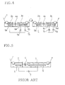
- a series combination of a plurality of units shown in Fig. 5 is called multi-stage power supply electrolytic process.
- a set of units comprising a first power supply part, a first middle part and a first electrolytic part arranged in this order is followed by another set of units comprising a second power supply part, a second middle part and a second electrolytic part arranged in this order.
- the electrolytic part and the power supply part are each filled with an electrolyte.
- an electrolytic electrode In each of these electrolytic parts was provided an electrolytic electrode.
- a power supply electrode In each of these power supply parts was provided a power supply electrode.
- the first power supply electrode is connected to the plus terminal of a d.c. power source while the first electrolytic electrode is connected to the minus terminal of the d.c. power source.
- the second power supply electrode is connected to the plus terminal of another d.c. power source while the second electrolytic electrode is connected to the minus terminal of the d.c, power source.
- the aluminum material is allowed to advance while the d.c. power source is on.
- a d.c. current then flows from the power supply electrode in the power supply part to the aluminum material via the electrolyte.
- the electric current then flows to the electrolytic electrode via the electrolyte in the electrolytic part.
- the electric current then returns to the power source. Accordingly, the aluminum material acts as an anode in the electrolytic part to form an anodized film on the surface thereof opposed to the electrode.
- a two-stage electrolytic treatment process which comprises anodizing a roughened aluminum plate in a sulfuric acid electrolyte, and then anodizing the aluminum plate in an electrolyte comprising sulfuric acid and phosphoric acid to improve the printing durability, developability and corrosiveness of a lithographic printing plate support made of aluminum or aluminum alloy is disclosed in U.S. Patent 4,396,470.
- U.S. Patent 4,554,057 and JP-A-58-153699 disclose a two-stage electrolytic process which comprises anodizing an aluminum material in a sulfuric acid-based electrolyte, and then anodizing the aluminum material in a water-soluble electrolyte comprising an anion containing phosphorus or a water-soluble electrolyte containing arsenic, vanadium, molybdenum, etc.
- This process makes it possible to enhance the alkali resistance of a chemically, mechanically and/or electrochemically roughened lithographic printing plate support.
- This process can be effected at a relatively high speed on the state-of-the-art belt type apparatus without adding to the production cost.
- This process is little or not liable to redissolution of oxide, making it possible to maintain the known definite properties of the anodized film produced by the anodization in a sulfuric acid solution.
- JP-B-4-37159 discloses a two-stage electrolytic process which comprises anodizing an aluminum material in a phosphoric acid electrolyte, and then anodizing the aluminum material in a sulfuric acid electrolyte to prevent a mechanically, chemically and/or electrochemically roughened lithographic printing plate support from being fogged by a dye or the like, improve the contrast of image area with non-image area on the printing plate and enhance the alkali resistance of the support.
- U.S. Patent 4,606,975 discloses a two-stage electrolytic process which comprises anodizing an aluminum material in a phosphoric acid-free electrolyte, and then anodizing the aluminum material in a sulfuric acid electrolyte. This process can be allegedly effected at a high speed on the state-of-the-art production line without adding to the production cost to provide a mechanically, chemically and/or electrochemically roughened lithographic printing plate support excellent in alkali resistance.
- the foregoing conventional submerged power-supplied electrolytic processes are disadvantageous in that when an aluminum material on which an anodized film has been formed at the electrolytic part is passed to the post-stage power supply part or the power supply part after the second stage unit in an electrolytic apparatus comprising a plurality of electrolytic units where it is then supplied with electric current (hereinafter referred to as "post-stage power supply process"), the anodized film may be locally destroyed and, in the extreme case, come off, making it impossible to form a uniform film on the surface of the aluminum material and hence provide the desired aluminum product.
- post-stage power supply process an electrolytic apparatus comprising a plurality of electrolytic units where it is then supplied with electric current
- the foregoing conventional submerged power-supplied electrolytic processes are also disadvantageous in that when a sheet aluminum material is anodized at the electrolytic part to form an anodized film thereon, electric current is concentrated on the edge of the sheet or escapes to the surface of the sheet opposite the anodized surface. Thus, an anodized film is formed more on the edge on the surface of the sheet opposed to the electrode and the other surface thereof.
- the anodized film may more easily be destroyed or come off on the edge on the surface of the sheet opposed to the electrode and the other surface thereof than on the central part of the sheet, making it impossible to provide the desired product as in the foregoing case.
- the electric current which has been supplied at the post-stage power supply part then flows through the anodized film into the aluminum material in the direction opposite to that at the electrolytic part.
- the passage of electric current in this direction is called cathodic polarization of anodized film. It is said that cathodic polarization causes local destruction of anodized film and dissolution of metal substrate to form pits therein.
- the possible mechanism of this phenomenon is as follows.
- hydrogen ions in the electrolyte penetrate into the barrier layer in the anodized film through defects in the film. The hydrogen ions then discharge electricity at the metal substrate-barrier layer interface to produce a hydrogen gas.
- the produced amount of hydrogen gas increases, the anodized film is destroyed. Electric current is concentrated on the destroyed points around of which the pH value is increased to cause local dissolution.
- the present invention provides an anodizing method which comprises further supplying electric current to aluminum or aluminum alloy which has been anodized at a power supply part and an electrolytic part through the anodized surface thereof.
- FIGs. 2 and 3 Examples of electrolytic apparatus for effecting the foregoing anodizing method are shown in Figs. 2 and 3.
- a further example of such an electrolytic apparatus is one comprising two or more of the conventional unit shown in Fig. 5 longitudinally connected to each other continuously or intermittently as shown in Fig. 4 (two-unit type).
- the electrolytic apparatus shown in Figs. 2 and 3 are adapted for anodization with d.c. current.
- These electrolytic apparatus each comprise an electrolytic part 3 for anodizing an aluminum web 1, a pre-stage power supply part 2a and a post-stage power supply part 2b provided before and after the electrolytic part 3 (with respect to the running direction of the aluminum material), respectively, for supplying electric current to the aluminum web 1, and a pre-stage middle part 4a and a post-stage middle part 4b provided between the pre-stage power supply part 2a and the electrolytic part 3 and between the electrolytic part 3 and the post-stage power supply part 2b, respectively.
- the electrolytic part 3 and the pre-stage and post-stage power supply parts 2a and 2b are filled with an electrolyte.
- electrolytic electrodes 6a, 6b, 6c and 6d are provided in the electrolytic part.
- pre-stage and post-stage power supply parts 2a and 2b are provided pre-stage and post-stage power supply electrodes 5a and 5b, respectively.
- the pre-stage and post-stage power supply electrodes 5a and 5b are connected to the plus terminal of d.c. power sources 7a, 7b, 7c and 7d while the electrolytic electrodes 6a, 6b, 6c and 6d are connected to the minus terminal of the d.c. power sources 7a, 7b, 7c and 7d, respectively.
- the aluminum web 1 is arranged to advance through the electrolyte in the electrolytic part 3 and the pre-stage and post-stage power supply parts 2a and 2b from left to right as viewed on the drawing.
- the process shown in Fig. 2 is referred to as “power source sharing process” while the process shown in Fig. 3 is referred to as "power source separation process”.
- Fig. 4 illustrates an apparatus comprising a plurality of units of Fig. 5 connected to each other as mentioned above (referred to as "two-stage electrolytic process").
- This apparatus comprises first and second electrolytic parts 3a and 3b for anodizing an aluminum web 1, first and second power supply parts 2a and 2b provided before the first and second electrolytic parts 3a and 3b, respectively, for supplying electric current to the aluminum web 1, and first and second middle parts 4a and 4b provided between the first power supply part 2a and the first electrolytic part 3a and between the second power supply part 2b and the second electrolytic part 3b, respectively.
- the apparatus shown in Fig. 4 employs a two-stage process. However, the number of stages is not specifically limited.
- the electrolytic parts 3a and 3b and the first and second power supply parts 2a and 2b are filled with an electrolyte.
- electrolytic electrodes 6a and 6b and electrolytic electrodes 6c and 6d respectively.
- first and second power supply parts 2a and 2b are provided first and second electrodes 5a and 5b, respectively.
- the first power supply electrode 5a is connected to the plus terminal of d.c. power sources 7a and 7b while the first electrolytic electrodes 6a and 6b are connected to the minus terminal of the d.c. power sources 7a and 7b, respectively.
- the second power supply electrode 5b is connected to the plus terminal of d.c. power sources 7c and 7d while the second electrolytic electrodes 6c and 6d are connected to the minus terminal of the d.c. power sources 7c and 7d, respectively.
- electric current is possibly supplied to the aluminum web through the surface which has been anodized at the various electrolytic parts.
- electric current is unavoidably supplied through the anodized film, possibly causing a post-stage power supply that destroys or spalls anodized film. It is thought that the degree of this phenomenon depends on the produced amount of hydrogen gas, the escaped amount of hydrogen gas thus produced and the structure and strength of the film through which hydrogen gas escapes. Thus, extensive studies have been made of the destruction and spalling of anodized film.
- the amount of anodized film thus formed depends on the kind of aluminum material on which it is formed.
- the thickness of anodized film thus formed is tens of micrometers.
- the thickness of anodized film thus formed is about 1.3 ⁇ m at maximum.
- the destruction and spalling of anodized film is related to the amount of anodized film formed after the pre-stage power supply process.
- the amount of anodized film thus formed is great, the anodized film can easily undergo destruction and spalling.
- the amount of anodized film thus formed is small, the anodized film is insusceptible to destruction and spalling.
- the amount of anodized film thus formed is advantageously small.
- the destruction and spalling of the anodized film doesn't depend on the amount of anodized film formed after the pre-stage power supply process alone.
- the destruction and spalling of the anodized film is related to the amount of anodized film thus formed as well as the post-stage current density and the post-stage power supply time.
- the amount of anodized film formed at the pre-stage power supply process is great, when the current density at the post-stage power supply process is small and the post-stage power supply time is short, the anodized film thus formed is insusceptible to destruction and spalling.
- the amount of anodized film formed at the pre-stage power supply process is small, when the current density at the post-stage power supply process is great and the post-stage power supply time is long, the anodized film thus formed can easily undergo destruction and spalling. Accordingly, it cannot be absolutely said that the amount of anodized film is advantageously small.
- the amount of anodized film to be formed on a lithographic printing plate support is almost unequivocally determined by the requirements for quality design such as printing properties. Therefore, the post-stage current density and the post-stage power supply time which cannot cause destruction and spalling of anodized film can be determined with the amount of anodized film fixed to the foregoing predetermined value.
- the amount of anodized film to be formed on a lithographic printing plate support is smaller than that to be formed on an anodized aluminum product. At present, it is from about 4.0 g/m 2 to 5.0 g/m 2 at maximum at the central part of the web.
- a support having an anodized film in an amount of from about 4.0 g/m 2 to 5.0 g/m 2 at maximum is supplied with electric current.
- a support having an anodized film in an amount of from about 2.0 g/m 2 to 2.5 g/m 2 at maximum is supplied with electric current.
- an anodized film is formed greater at the edge of the web than at the central part of the web.
- the electrodes may be disposed on both surfaces of the aluminum web or on either the anodized film surfaces of the aluminum web or the other surface of the aluminum web.
- the current density depends on the disposition of the electrodes relative to the aluminum web. For example, if the electrodes are disposed on both surfaces of an aluminum web, the area supplied with electric current is the sum of the product of the length of the electrode and the width of the aluminum web on both surfaces of the aluminum web. If the electrodes are disposed on one surface of the aluminum web, the area supplied with electric current is the product of the length of the electrode disposed on one either surface of the aluminum web and the width of the aluminum web. The current density is obtained by dividing the supplied amount of electric current by the area thus calculated.
- the current density on the anodized film of the aluminum web is lower than that on the other surface.
- the current density on the anodized film of the aluminum web decreases further. Accordingly, in order to determine accurate current density on each surface of the aluminum web, it is necessary to investigate the proportion of electric current distributed to the anodized film and the other surface of the aluminum web for the various amounts of anodized film.
- the current density at the post-stage power supply process which doesn't cause destruction and spalling of anodized film at the edge of the web is determined by the amount of anodized film at the edge of the web, the amount of electric current required at the power supply part, the area supplied with electric current and the power supply time. If the double-power supplied electrolytic process and the two-stage power supply electrolytic process are conducted under the same power supply conditions, the two-stage power supply electrolytic process, which produces less anodized film during the post-stage power supply process, is favorable for the prevention of destruction and spalling of anodized film.
- the post-stage power supply time is predetermined by the length of the power supply electrode and the running speed of the aluminum web. If it is desired to form a predetermined amount of anodized film, when the power supply electrode is long or the running speed of the aluminum web is low, the required power supply time is long, which is generally unfavorable for the prevention of destruction and spalling of anodized film. However, this involves a reduced amount of electric current and a reduced current density and is not necessarily unfavorable for the foregoing requirements. On the contrary, when the power supply electrode is short or the running speed of the aluminum web is high, the required power supply time is short, which is generally favorable for the prevention of destruction and spalling of anodized film.
- the double-power supply electrolytic process and the two-stage power supply electrolytic process are conducted under the same power supply time conditions, the two-stage power supply electrolytic process, which produces less anodized film during the post-stage power supply process, is favorable for the prevention of destruction and spalling of anodized film.
- Representative examples of the electrolyte through which electric current is supplied at the post-stage power supply process include an aqueous solution of sulfuric acid, phosphoric acid, oxalic acid, and salt thereof, and mixture thereof.
- the optimum electrolyte may be selected from these aqueous solutions to obtain the desired product quality.
- the concentration and temperature of the electrolyte may be freely selected.
- the electrolytic part and the power supply part may have the same or different electrolytes.
- the optimum waveform of electric current supplied from the power source may be selected from the group consisting of d.c. wave, a.c. wave and a.c.-superimposed d.c. wave to obtain the desired product quality.
- the aluminum web there may be used any aluminum material to be subjected to anodization.
- the aluminum material for a lithographic printing plate support there may be used any known aluminum plate such as JIS A1050 and JIS A1100.
- the foregoing aluminum materials may be subjected to pretreatment, etching and mechanical, chemical or electrochemical roughening by a known technique.
- the aluminum material thus treated is then subjected to anodization according to the present invention.
- the aluminum material is then subjected to known hydrophilic treatment as necessary.
- the aluminum material is then provided with an undercoating layer, a photosensitive resin layer and a matting layer. In this manner, the desired photosensitive lithographic printing plate can be prepared.
- the condition under which the anodized film undergoes neither destruction nor spalling during the post-stage power supply process can be defined by the relationship that the product of (current density) 4/3 , (power supply time) 3/2 and (amount of anodized film) 2/3 is not more than 5,100. It can be said that the destruction and spalling of anodized film can be affected by power supply time, current density and amount of anodized film, which increase in that order. The power supply time and amount of anodized film have a predetermined range. This means that if the foregoing conditions are not satisfied, the anodized film undergoes destruction and spalling in the case of a lithographic printing plate support in particular.
- the amount of anodized film to be formed thereon is preferentially determined from the standpoint of quality design. Therefore, the power supply time and post-stage current density can be most suitably determined. This means that, for example, if the required amount of anodized film is 4.0 g/m 2 , which requires that the anodized film occurs in an amount of 4.0 g/m 2 during the post-stage power supply process in the double-power supplied electrolytic process, the power supply time may be 8 seconds, 6 seconds or 4 seconds so that the density of electric current supplied through the anodized film is determined to not more than about 29.1 [A/dm 2 ], not more than about 40.2 [A/dm 2 ] or not more than about 63.4 [A/dm 2 ], respectively, which causes neither destruction nor spalling of anodized film.
- the amount of electric current supplied into the first stage and second stage electrolytic parts may be equal to each other. Since the anodized film formed at the first stage electrolytic part exists in an amount of 2.0 g/m 2 when supplied with electric current at the post-stage power supply process at the second stage electrolytic part, the power supply time may be 8 seconds, 6 seconds or 4 seconds so that the density of electric current supplied through the anodized film is determined to not more than about 41.1 [A/dm 2 ], not more than about 56.8 [A/dm 2 ] or not more than about 89.7 [A/dm 2 ], respectively, which causes neither destruction nor spalling of anodized film. From the standpoint of density of electric current supplied at the post-stage power supply process, the two-stage power supply electrolytic process is favorable for the prevention of destruction and spalling of anodized film.
- the optimum power supply time and current density which don't cause destruction and spalling of anodized film during the post-stage power supply step can be selected.
- anodizing apparatus having the construction shown in Fig. 5 (length of electrolytic part: 12 m; length of power supply part: 3 m) and a continuous aluminum web treatment apparatus (not described in detail) comprising a mechanical roughening apparatus, an etching apparatus and an electrochemical roughening apparatus
- aluminum webs having a thickness of 0.24 mm and a width of 1,000 mm were anodized with varied supplied amounts of electric current while being conveyed at a speed of 36 m/min to form anodized films thereon in an amount of 0.8 g/m 2 , 1.5 g/m 2 , 2.5 g/m 2 , 4.0 g/m 2 and 5.5 g/m 2 , respectively.
- These anodized aluminum webs were each then wound.
- These anodized aluminum webs were each then cut while being unwound to give normally anodized samples (Samples A, B, C, D and E).
- the electrolyte there was used an aqueous solution of sulfuric acid common to the electrolytic part and the power supply part.
- the treatment in the apparatus other than the anodizing apparatus was fixed.
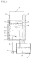
- the foregoing electrolytic apparatus comprises an electrolytic bath 11 composed of an electrode 8 made of carbon, a sample fixture 9 and a treatment bath 10, a d.c. power source 12, a reservoir 14 for storing an electrolyte 13, and a pump 15 for circulating the electrolyte 13.
- the electrolyte 13 is supplied into the treatment bath 10 through a feed pipe 16 and an electrolyte inlet 17 on the treatment bath 10.
- the electrolyte 13 thus supplied is mainly returned to the reservoir 14 through an electrolyte outlet 18 and a return pipe 19.
- the other part of the electrolyte 13 is returned to the reservoir 14 through an overflow port 20 and an overflow pipe 21.
- the electrolyte 13 in the reservoir 14 is controlled to a predetermined temperature by means of a controller (not shown).
- the electrode 8 in the electrolytic bath 11 is connected to the plus terminal of the d.c. power source 12.
- the sample is connected to the minus terminal of the d.c. power source.
- electric current is supplied from the d.c. power source 12 under these conditions, it flows through the electrode 8 and the electrolyte 13.
- the electric current then flows into a sample 22 through an anodized film on the area (power-supplied area) other than that covered by an insulating tape 23.
- the electric current then flows back to the d.c. power source 12.
- the distance between the electrode 8 and the sample 22 was 50 mm.
- As the electrolyte 13 there was used an aqueous solution of sulfuric acid (concentration of sulfuric acid: 150 g/l; temperature: 35°C).
- the sample 22 was covered by a plastic insulating tape 23 on the submerged area other than the power-supplied area so that electric current was passed through the power-supplied area alone.
- the power-supplied area was 25 cm 2
- a table having a corner with an angle of 150 degrees and R of 2 mm was prepared.
- the sample was pressed against the corner of the table with the anodized surface thereof upside so that it was folded at an angle of 30 degrees.
- the sample was turned over, and then pressed against the table with the folded point put on the corner so that it was folded the other way by 60 degrees.
- the sample was turned over, and then folded the other way by 30 degrees with the folded point put on the corner until it was flat.
- the sample thus folded was cracked.
- Samples A, B, C, D and E were each supplied with electric current for 1 second, 3 seconds, 5 seconds, 8 seconds and 10 seconds.
- the results of evaluation of these samples are set forth in Tables 1, 2, 3, 4 and 5.
- the blanks in these tables mean that no samples were prepared or evaluated.
- the symbols have the following meaning: G: No spalling occurred; F: Some spalling occurred; P: Spalling occurred
- the resulting supplied amount of electric current (A) was converted to current density (A/dm 2 ).
- the relationship among current density, power supply time (sec.) and amount of anodized film (g/m 2 ) which doesn't cause destruction and spalling of anodized film was determined and represented by the foregoing experimental equation.
- an aluminum web continuous treatment apparatus comprising a power source separation type double-power supplied electrolytic process anodizing apparatus (length of electrolytic part: 12 m; length of pre-stage power supply part: 3 m; length of post-stage power supply part: 3 m; length of pre-stage and post-stage power supply electrodes: 2.4 m) having the construction shown in Fig. 3, a mechanical roughening apparatus, an etching apparatus and an electrochemical roughening apparatus, an aluminum web having a thickness of 0.24 mm and a width of 1,000 mm was anodized while being conveyed at a speed of 36 m/min. to form an anodized film thereon in an amount of 2.4 g/m 2 , and then was wound.
- a power source separation type double-power supplied electrolytic process anodizing apparatus length of electrolytic part: 12 m; length of pre-stage power supply part: 3 m; length of post-stage power supply part: 3 m; length of pre-stage and post-stage power supply electrodes: 2.4
- the electric current then flows into the aluminum web through the electrolyte so that an anodized film is formed on the surface of the aluminum web in the electrolytic part 3.
- the amount of electric current to be supplied from the power sources 7a and 7b into the pre-stage power supply part 2 was adjusted the same as the amount of electric current to be supplied from the power sources 7c and 7d into the post-stage power supply part 2b.
- the density of electric current supplied through the anodized film in the post-stage power supply part 2b was about 23 (A/dm 2 ).
- electric current was supplied into the aluminum web through the area which had been anodized in an amount of 2.4 g/m 2 .
- the treatment conditions other than electrolyte and anodizing apparatus were the same as in Example 1.
- Sample F was then evaluated for anodized film properties in the same manner as in Example 1. As a result, the anodized film was found to undergo neither destruction nor spalling at the central part and edge of the sample.
- Example 2 The procedure of Example 2 was followed to effect anodization except that a power source sharing type double-power supplied electrolytic process anodizing apparatus (length of electrolytic part: 12 m; length of pre-stage power supply part: 3 m; length of post-stage power supply part: 3 m; length of pre-stage and post-stage power supply electrodes: 2.4 m) was employed in which the plus terminal of the power sources 7a, 7b, 7c and 7d were all connected to the power supply electrodes 5a and 5b so that electric current from these power sources were supplied into the pre-stage power supply electrode 5a and the post-stage power supply electrode 5b.
- an anodized film was formed on an aluminum web in an amount of 2.4 g/m 2 . The aluminum web thus anodized was then wound.
- electric current from the power sources 7a, 7b, 7c and 7d is distributed to the pre-stage power supply part 2a and the post-stage power supply part 2b in such a manner that the electrical resistance of the entire anodizing apparatus is minimized.
- the electric current which has flown into the pre-stage power electrode 5a provided in the pre-stage power supply part 2a, and then flown into the aluminum web through the electrolyte causes the aluminum web to be anodized on the surface thereof in the electrolytic part 3.
- the electric current is then returned to the power sources through any of the electrolytic electrodes 6a, 6b, 6c and 6d provided in the electrolytic part 3.
- the electric current which has flown into the post-stage power electrode 5b provided in the post-stage power supply part 2b, and then flown into the aluminum web through the electrolyte causes the aluminum web to be anodized on the surface thereof in the electrolytic part 3.
- the electric current is then returned to the power sources through any of the electrolytic electrodes 6a, 6b, 6c and 6d provided in the electrolytic part 3.
- the amount of electric current to be supplied from the power sources 7a and 7b into the pre-stage power supply part 2 was adjusted the same as the amount of electric current to be supplied from the power sources 7c and 7d into the post-stage power supply part 2b.
- the density of electric current to be supplied through the anodized film in the post-stage power supply part 2b is estimated to be about 23 (A/dm 2 ), but this is not accurate.
- electric current was supplied into the aluminum web through the area which had been anodized in an amount of 2.4 g/m 2 .
- Sample G was then evaluated for anodized film properties in the same manner as in Example 1. As a result, the anodized film was found to undergo neither destruction nor spalling at the central part and edge of the sample.
- a continuous aluminum web treatment apparatus comprising a two-stage power supply electrolytic process anodizing apparatus (length of first and second electrolytic parts: 6 m each; length of first and second power supply parts: 3 m each; length of first and second power supply electrodes: 2.4 m each) having the construction shown in Fig. 4, a mechanical roughening apparatus, an etching apparatus and an electrochemical roughening apparatus, an aluminum web having a thickness of 0.24 mm and a width of 1,000 mm was anodized while being conveyed at a speed of 36 m/min. to form an anodized film thereon in an amount of 2.4 g/m 2 , and then wound.
- electric current from the power sources 7c and 7d flows into the second power supply electrode 5b provided in the second power supply part 2b.
- the electric current then flows into the aluminum web through the electrolyte so that an anodized film is formed on the surface of the aluminum web in the second electrolytic part 3b.
- the amount of electric current to be supplied from the power sources 7a and 7b into the first power supply part 2a was adjusted the same as the amount of electric current to be supplied from the power sources 7c and 7d into the second power supply part 2b.
- the density of electric current supplied through the anodized film in the second power supply part 2b was about 23 (A/dm 2 ).
- electric current was supplied into the aluminum web through the area which had been anodized in an amount of 1.2 g/m 2 .
- the treatment conditions other than electrolyte and anodizing apparatus were the same as in Example 1.
- Sample H was then evaluated for anodized film properties in the same manner as in Example 1. As a result, the anodized film was found to undergo neither destruction nor spalling at the central part and edge of the sample.
- the conditions such as current density, amount of anodized film and power supply time can be optimized to prevent local destruction and spalling of anodized film, making it possible to form a uniform anodized film.
- an aluminum product which satisfies quality and property requirements can be provided.
- the process according to the present invention can be operated at a reduced power.
- the cooling burden and running cost can be reduced.
- no power source having great boosting properties is required. Further, troubles such as corrosion, spark and current leakage can be minimized.
Landscapes
- Chemical & Material Sciences (AREA)
- Engineering & Computer Science (AREA)
- Chemical Kinetics & Catalysis (AREA)
- Electrochemistry (AREA)
- Materials Engineering (AREA)
- Metallurgy (AREA)
- Organic Chemistry (AREA)
- Printing Plates And Materials Therefor (AREA)
- Catalysts (AREA)
- Other Surface Treatments For Metallic Materials (AREA)
Claims (16)
- Verfahren zur kontinuierlichen Anodisierung eines Aluminiumbandes, umfassend: Anodisieren der Oberfläche von länglichem Aluminium oder einer länglichen Aluminiumlegierung, das/die sich bewegt, mittels eines Stromversorgungsteils und eines Elektrolyseteils, und dann
Zuführen von elektrischem Strom zur Oberfläche des anodisierten Bandes mittels eines weiteren Stromversorgungsteils auf solche Weise, daß die nachstehenden Beziehungen zwischen der Stromdichte, der Stromzuführzeit und der Menge des so gebildeten anodisierten Films erfüllt sind: - Verfahren nach Anspruch 1, wobei die Menge an anodisiertem Film im Bereich zwischen 0,8 g/m2 und 5,5 g/m2 liegt.
- Verfahren nach Anspruch 1, wobei die Menge an anodisiertem Film im Bereich zwischen 1,5 g/m2 und 4 g/m2 liegt.
- Verfahren nach Anspruch 1, wobei die Menge an anodisiertem Film im Bereich zwischen 1,5 g/m2 und 2,5 g/m2 liegt.
- Verfahren nach Anspruch 1, wobei das Aluminiumband mittels einer Elektrolysevorrichtung mit doppelter Stromversorgung vom Typ mit gemeinsamer Stromquelle elektrolytisch behandelt wird.
- Verfahren nach Anspruch 2, wobei das Aluminiumband mittels einer Elektrolysevorrichtung mit doppelter Stromversorgung vom Typ mit gemeinsamer Stromquelle elektrolytisch behandelt wird.
- Verfahren nach Anspruch 3, wobei das Aluminiumband mittels einer Elektrolysevorrichtung mit doppelter Stromversorgung vom Typ mit gemeinsamer Stromquelle elektrolytisch behandelt wird.
- Verfahren nach Anspruch 4, wobei das Aluminiumband mittels einer Elektrolysevorrichtung mit doppelter Stromversorgung vom Typ mit gemeinsamer Stromquelle elektrolytisch behandelt wird.
- Verfahren nach Anspruch 1, wobei das Aluminiumband mittels einer Elektrolysevorrichtung mit doppelter Stromversorgung vom Typ mit getrennter Stromquelle elektrolytisch behandelt wird.
- Verfahren nach Anspruch 2, wobei das Aluminiumband mittels einer Elektrolysevorrichtung mit doppelter Stromversorgung vom Typ mit getrennter Stromquelle elektrolytisch behandelt wird.
- Verfahren nach Anspruch 3, wobei das Aluminiumband mittels einer Elektrolysevorrichtung mit doppelter Stromversorgung vom Typ mit getrennter Stromquelle elektrolytisch behandelt wird.
- Verfahren nach Anspruch 4, wobei das Aluminiumband mitels einer Elektrolysevorrichtung mit doppelter Stromversorgung vom Typ mit getrennter Stromquelle elektrolytisch behandelt wird.
- Verfahren nach Anspruch 1, wobei das Aluminiumband mittels einer Elektrolysevorrichtung mit zweistufiger Stromversorgung elektrolytisch behandelt wird.
- Verfahren nach Anspruch 2, wobei das Aluminiumband mittels einer Elektrolysevorrichtung mit zweistufiger Stromversorgung elektrolytisch behandelt wird.
- Verfahren nach Anspruch 3, wobei das Aluminiumband mittels einer Elektrolysevorrichtung mit zweistufiger Stromversorgung elektrolytisch behandelt wird.
- Verfahren nach Anspruch 4, wobei das Aluminiumband mittels einer Elektrolysevorrichtung mit zweistufiger Stromversorgung elektrolytisch behandelt wird.
Applications Claiming Priority (3)
| Application Number | Priority Date | Filing Date | Title |
|---|---|---|---|
| JP172513/96 | 1996-07-02 | ||
| JP17251396 | 1996-07-02 | ||
| JP17251396A JP3705457B2 (ja) | 1996-07-02 | 1996-07-02 | アルミニウム材の陽極酸化処理方法 |
Publications (2)
| Publication Number | Publication Date |
|---|---|
| EP0816536A1 EP0816536A1 (de) | 1998-01-07 |
| EP0816536B1 true EP0816536B1 (de) | 2000-01-12 |
Family
ID=15943356
Family Applications (1)
| Application Number | Title | Priority Date | Filing Date |
|---|---|---|---|
| EP97110805A Expired - Lifetime EP0816536B1 (de) | 1996-07-02 | 1997-07-01 | Verfahren zur Anodisierung eines Aluminiummaterials |
Country Status (5)
| Country | Link |
|---|---|
| US (1) | US5851373A (de) |
| EP (1) | EP0816536B1 (de) |
| JP (1) | JP3705457B2 (de) |
| AT (1) | ATE188753T1 (de) |
| DE (1) | DE69701110T2 (de) |
Families Citing this family (16)
| Publication number | Priority date | Publication date | Assignee | Title |
|---|---|---|---|---|
| JP2000297397A (ja) * | 1999-02-10 | 2000-10-24 | Canon Inc | 電析方法 |
| JP2001140100A (ja) * | 1999-11-12 | 2001-05-22 | Fuji Photo Film Co Ltd | 金属板電解処理装置及び金属板電解処理用電極 |
| US6674533B2 (en) * | 2000-12-21 | 2004-01-06 | Joseph K. Price | Anodizing system with a coating thickness monitor and an anodized product |
| US7365860B2 (en) * | 2000-12-21 | 2008-04-29 | Sensory Analytics | System capable of determining applied and anodized coating thickness of a coated-anodized product |
| US7274463B2 (en) * | 2003-12-30 | 2007-09-25 | Sensory Analytics | Anodizing system with a coating thickness monitor and an anodized product |
| US7527872B2 (en) * | 2005-10-25 | 2009-05-05 | Goodrich Corporation | Treated aluminum article and method for making same |
| US20070222460A1 (en) * | 2006-03-07 | 2007-09-27 | Price Joseph K | Mobile apparatus capable of surface measurements |
| US8900716B2 (en) * | 2008-02-11 | 2014-12-02 | Lorin Industries, Inc. | Antimicrobial anodized aluminum and related method |
| CN101565823B (zh) * | 2009-05-19 | 2011-09-07 | 温贤林 | 卷盘铝带表面处理工艺 |
| US8512872B2 (en) | 2010-05-19 | 2013-08-20 | Dupalectpa-CHN, LLC | Sealed anodic coatings |
| US8609254B2 (en) | 2010-05-19 | 2013-12-17 | Sanford Process Corporation | Microcrystalline anodic coatings and related methods therefor |
| US20120186981A1 (en) * | 2010-11-09 | 2012-07-26 | Lorin Industries, Inc. | Antimicrobial process on metal |
| CN102080246B (zh) * | 2010-12-03 | 2012-08-15 | 浙江丰川电子科技有限公司 | 中高压电极箔高速生产装置 |
| KR101502042B1 (ko) * | 2013-08-19 | 2015-03-18 | 주식회사 우존 | 반사 패턴 형성 장치 및 방법 |
| FR3020642B1 (fr) * | 2014-04-30 | 2021-07-02 | Turbomeca | Dispositif destine a la mise en oeuvre d'un traitement d'anodisation |
| JP6720541B2 (ja) * | 2016-01-14 | 2020-07-08 | 日本軽金属株式会社 | アルミニウム電解コンデンサ用電極の製造方法および化成装置 |
Family Cites Families (10)
| Publication number | Priority date | Publication date | Assignee | Title |
|---|---|---|---|---|
| GB2088901B (en) * | 1980-10-23 | 1983-12-07 | Vickers Ltd | Anodised aluminium sheet for lithographic printing plate production |
| DE3270988D1 (en) * | 1981-07-20 | 1986-06-12 | Upjohn Co | Use of ibuprofen or flurbiprofen for the manufacture of a medicament for treating respiratory disorders |
| DE3206469A1 (de) * | 1982-02-23 | 1983-09-01 | Hoechst Ag, 6230 Frankfurt | Verfahren zur herstellung von traegermaterialien fuer offsetdruckplatten |
| DE3206470A1 (de) * | 1982-02-23 | 1983-09-01 | Hoechst Ag, 6230 Frankfurt | Verfahren zur herstellung von traegermaterialien fuer offsetdruckplatten |
| DE3312497A1 (de) * | 1983-04-07 | 1984-10-11 | Hoechst Ag, 6230 Frankfurt | Zweistufiges verfahren zur herstellung von anodisch oxidierten flaechigen materialien aus aluminium und deren verwendung bei der herstellung von offsetdruckplatten |
| DE3328048A1 (de) * | 1983-08-03 | 1985-02-21 | Hoechst Ag, 6230 Frankfurt | Verfahren zur zweistufigen anodischen oxidation von traegermaterialien aus aluminium fuer offsetdruckplatten |
| US4872946A (en) * | 1987-02-23 | 1989-10-10 | Fuji Photo Film Co., Ltd. | Method of manufacturing supports for lithographic printing plate |
| US4865699A (en) * | 1988-06-24 | 1989-09-12 | Fromson H A | Process and apparatus for anodizing aluminum |
| US5181997A (en) * | 1990-06-19 | 1993-01-26 | Fuji Photo Film Co., Ltd. | Apparatus and method for continuously electrolyzing aluminum products |
| JP2646042B2 (ja) * | 1991-03-07 | 1997-08-25 | 富士写真フイルム株式会社 | アルミニウム製品の連続電解処理装置 |
-
1996
- 1996-07-02 JP JP17251396A patent/JP3705457B2/ja not_active Expired - Fee Related
-
1997
- 1997-07-01 DE DE69701110T patent/DE69701110T2/de not_active Expired - Lifetime
- 1997-07-01 US US08/886,539 patent/US5851373A/en not_active Expired - Lifetime
- 1997-07-01 AT AT97110805T patent/ATE188753T1/de not_active IP Right Cessation
- 1997-07-01 EP EP97110805A patent/EP0816536B1/de not_active Expired - Lifetime
Also Published As
| Publication number | Publication date |
|---|---|
| DE69701110D1 (de) | 2000-02-17 |
| US5851373A (en) | 1998-12-22 |
| JPH1018084A (ja) | 1998-01-20 |
| JP3705457B2 (ja) | 2005-10-12 |
| DE69701110T2 (de) | 2000-06-15 |
| ATE188753T1 (de) | 2000-01-15 |
| EP0816536A1 (de) | 1998-01-07 |
Similar Documents
| Publication | Publication Date | Title |
|---|---|---|
| EP0816536B1 (de) | Verfahren zur Anodisierung eines Aluminiummaterials | |
| US6143158A (en) | Method for producing an aluminum support for a lithographic printing plate | |
| EP0701908B1 (de) | Aluminium-Träger für eine Flachdruckplatte, Verfahren zu ihrer Herstellung und Aufrauhung | |
| US4533444A (en) | Method of electrolytic treatment on the surface of metal web | |
| US5207881A (en) | Apparatus for continuous electrolytic treatment of aluminum article | |
| US4551210A (en) | Dendritic treatment of metallic surfaces for improving adhesive bonding | |
| US6979391B1 (en) | Method and device for the electrolytic treatment of electrically conducting structures which are insulated from each other and positioned on the surface of electrically insulating film materials and use of the method | |
| KR100729973B1 (ko) | 상호 절연된 시트 및 포일 재료 피스의 도전성 표면을 전해 처리하는 방법 및 장치 | |
| US5152877A (en) | Method for producing support for printing plate | |
| US4692221A (en) | In-situ dendritic treatment of electrodeposited foil | |
| US4929326A (en) | Electrolytic treatment apparatus | |
| US5181997A (en) | Apparatus and method for continuously electrolyzing aluminum products | |
| JP3729013B2 (ja) | アルミ電解コンデンサ用電極箔の製造方法 | |
| US4536264A (en) | Method for electrolytic treatment | |
| US4559114A (en) | Nickel sulfate coloring process for anodized aluminum | |
| US4406757A (en) | Anodization method | |
| US5314607A (en) | Apparatus and method for anodizing supports for lithographic printing plate | |
| US6344131B1 (en) | Method of producing aluminum support for planographic printing plate | |
| JP2632235B2 (ja) | アルミニウム製品の連続電解処理装置および方法 | |
| JPH021391A (ja) | 印刷版用アルミニウム支持体の製造方法 | |
| US5213666A (en) | Method of preparing support for printing plate | |
| JP3625103B2 (ja) | 平版印刷版支持体の電解処理方法 | |
| JP2715346B2 (ja) | 印刷版用アルミニウム支持体の電解処理方法 | |
| NAKAJIMA et al. | Development of liquid contacting system for forming of aluminum foil for electrolytic capacitors and its commercialization | |
| JPS5920498A (ja) | アルミニウム板の連続的片面電解処理法 |
Legal Events
| Date | Code | Title | Description |
|---|---|---|---|
| PUAI | Public reference made under article 153(3) epc to a published international application that has entered the european phase |
Free format text: ORIGINAL CODE: 0009012 |
|
| AK | Designated contracting states |
Kind code of ref document: A1 Designated state(s): AT BE CH DE DK ES FI FR GB GR IE IT LI LU MC NL PT SE |
|
| 17P | Request for examination filed |
Effective date: 19980610 |
|
| AKX | Designation fees paid |
Free format text: AT BE CH DE DK ES FI FR GB GR IE IT LI LU MC NL PT SE |
|
| RBV | Designated contracting states (corrected) |
Designated state(s): AT BE CH DE DK ES FI FR GB GR IE IT LI LU MC NL PT SE |
|
| GRAG | Despatch of communication of intention to grant |
Free format text: ORIGINAL CODE: EPIDOS AGRA |
|
| 17Q | First examination report despatched |
Effective date: 19990212 |
|
| GRAG | Despatch of communication of intention to grant |
Free format text: ORIGINAL CODE: EPIDOS AGRA |
|
| GRAH | Despatch of communication of intention to grant a patent |
Free format text: ORIGINAL CODE: EPIDOS IGRA |
|
| GRAH | Despatch of communication of intention to grant a patent |
Free format text: ORIGINAL CODE: EPIDOS IGRA |
|
| GRAA | (expected) grant |
Free format text: ORIGINAL CODE: 0009210 |
|
| AK | Designated contracting states |
Kind code of ref document: B1 Designated state(s): AT BE CH DE DK ES FI FR GB GR IE IT LI LU MC NL PT SE |
|
| PG25 | Lapsed in a contracting state [announced via postgrant information from national office to epo] |
Ref country code: SE Free format text: THE PATENT HAS BEEN ANNULLED BY A DECISION OF A NATIONAL AUTHORITY Effective date: 20000112 Ref country code: NL Free format text: LAPSE BECAUSE OF FAILURE TO SUBMIT A TRANSLATION OF THE DESCRIPTION OR TO PAY THE FEE WITHIN THE PRESCRIBED TIME-LIMIT Effective date: 20000112 Ref country code: LI Free format text: LAPSE BECAUSE OF FAILURE TO SUBMIT A TRANSLATION OF THE DESCRIPTION OR TO PAY THE FEE WITHIN THE PRESCRIBED TIME-LIMIT Effective date: 20000112 Ref country code: IT Free format text: LAPSE BECAUSE OF FAILURE TO SUBMIT A TRANSLATION OF THE DESCRIPTION OR TO PAY THE FEE WITHIN THE PRESCRIBED TIME-LIMIT;WARNING: LAPSES OF ITALIAN PATENTS WITH EFFECTIVE DATE BEFORE 2007 MAY HAVE OCCURRED AT ANY TIME BEFORE 2007. THE CORRECT EFFECTIVE DATE MAY BE DIFFERENT FROM THE ONE RECORDED. Effective date: 20000112 Ref country code: GR Free format text: LAPSE BECAUSE OF NON-PAYMENT OF DUE FEES Effective date: 20000112 Ref country code: FR Free format text: LAPSE BECAUSE OF FAILURE TO SUBMIT A TRANSLATION OF THE DESCRIPTION OR TO PAY THE FEE WITHIN THE PRESCRIBED TIME-LIMIT Effective date: 20000112 Ref country code: FI Free format text: LAPSE BECAUSE OF FAILURE TO SUBMIT A TRANSLATION OF THE DESCRIPTION OR TO PAY THE FEE WITHIN THE PRESCRIBED TIME-LIMIT Effective date: 20000112 Ref country code: ES Free format text: THE PATENT HAS BEEN ANNULLED BY A DECISION OF A NATIONAL AUTHORITY Effective date: 20000112 Ref country code: CH Free format text: LAPSE BECAUSE OF FAILURE TO SUBMIT A TRANSLATION OF THE DESCRIPTION OR TO PAY THE FEE WITHIN THE PRESCRIBED TIME-LIMIT Effective date: 20000112 Ref country code: BE Free format text: LAPSE BECAUSE OF FAILURE TO SUBMIT A TRANSLATION OF THE DESCRIPTION OR TO PAY THE FEE WITHIN THE PRESCRIBED TIME-LIMIT Effective date: 20000112 Ref country code: AT Free format text: LAPSE BECAUSE OF FAILURE TO SUBMIT A TRANSLATION OF THE DESCRIPTION OR TO PAY THE FEE WITHIN THE PRESCRIBED TIME-LIMIT Effective date: 20000112 |
|
| REF | Corresponds to: |
Ref document number: 188753 Country of ref document: AT Date of ref document: 20000115 Kind code of ref document: T |
|
| REG | Reference to a national code |
Ref country code: CH Ref legal event code: EP |
|
| REF | Corresponds to: |
Ref document number: 69701110 Country of ref document: DE Date of ref document: 20000217 |
|
| REG | Reference to a national code |
Ref country code: IE Ref legal event code: FG4D |
|
| PG25 | Lapsed in a contracting state [announced via postgrant information from national office to epo] |
Ref country code: PT Free format text: LAPSE BECAUSE OF FAILURE TO SUBMIT A TRANSLATION OF THE DESCRIPTION OR TO PAY THE FEE WITHIN THE PRESCRIBED TIME-LIMIT Effective date: 20000412 Ref country code: DK Free format text: LAPSE BECAUSE OF FAILURE TO SUBMIT A TRANSLATION OF THE DESCRIPTION OR TO PAY THE FEE WITHIN THE PRESCRIBED TIME-LIMIT Effective date: 20000412 |
|
| NLV1 | Nl: lapsed or annulled due to failure to fulfill the requirements of art. 29p and 29m of the patents act | ||
| EN | Fr: translation not filed | ||
| PG25 | Lapsed in a contracting state [announced via postgrant information from national office to epo] |
Ref country code: LU Free format text: LAPSE BECAUSE OF NON-PAYMENT OF DUE FEES Effective date: 20000701 |
|
| PG25 | Lapsed in a contracting state [announced via postgrant information from national office to epo] |
Ref country code: IE Free format text: LAPSE BECAUSE OF NON-PAYMENT OF DUE FEES Effective date: 20000703 |
|
| REG | Reference to a national code |
Ref country code: CH Ref legal event code: PL |
|
| PG25 | Lapsed in a contracting state [announced via postgrant information from national office to epo] |
Ref country code: MC Free format text: THE PATENT HAS BEEN ANNULLED BY A DECISION OF A NATIONAL AUTHORITY Effective date: 20000731 |
|
| PLBE | No opposition filed within time limit |
Free format text: ORIGINAL CODE: 0009261 |
|
| STAA | Information on the status of an ep patent application or granted ep patent |
Free format text: STATUS: NO OPPOSITION FILED WITHIN TIME LIMIT |
|
| 26N | No opposition filed | ||
| REG | Reference to a national code |
Ref country code: IE Ref legal event code: MM4A |
|
| PG25 | Lapsed in a contracting state [announced via postgrant information from national office to epo] |
Ref country code: GB Free format text: LAPSE BECAUSE OF NON-PAYMENT OF DUE FEES Effective date: 20010701 |
|
| GBPC | Gb: european patent ceased through non-payment of renewal fee |
Effective date: 20010701 |
|
| PGFP | Annual fee paid to national office [announced via postgrant information from national office to epo] |
Ref country code: DE Payment date: 20120627 Year of fee payment: 16 |
|
| REG | Reference to a national code |
Ref country code: DE Ref legal event code: R119 Ref document number: 69701110 Country of ref document: DE Effective date: 20140201 |
|
| PG25 | Lapsed in a contracting state [announced via postgrant information from national office to epo] |
Ref country code: DE Free format text: LAPSE BECAUSE OF NON-PAYMENT OF DUE FEES Effective date: 20140201 |