EP0814538A1 - Integrierte flache Antenne und Funkgerät für Punkt-zu-Punkt Mikrowellen-Funkverbindungen - Google Patents
Integrierte flache Antenne und Funkgerät für Punkt-zu-Punkt Mikrowellen-Funkverbindungen Download PDFInfo
- Publication number
- EP0814538A1 EP0814538A1 EP97109733A EP97109733A EP0814538A1 EP 0814538 A1 EP0814538 A1 EP 0814538A1 EP 97109733 A EP97109733 A EP 97109733A EP 97109733 A EP97109733 A EP 97109733A EP 0814538 A1 EP0814538 A1 EP 0814538A1
- Authority
- EP
- European Patent Office
- Prior art keywords
- antenna
- radio frequency
- frequency unit
- microwave
- housing
- Prior art date
- Legal status (The legal status is an assumption and is not a legal conclusion. Google has not performed a legal analysis and makes no representation as to the accuracy of the status listed.)
- Withdrawn
Links
- 238000004891 communication Methods 0.000 title claims description 7
- 238000013459 approach Methods 0.000 description 9
- 238000012545 processing Methods 0.000 description 7
- 238000010586 diagram Methods 0.000 description 2
- 238000000034 method Methods 0.000 description 2
- 238000004806 packaging method and process Methods 0.000 description 2
- 230000005540 biological transmission Effects 0.000 description 1
- 230000001413 cellular effect Effects 0.000 description 1
- 238000010276 construction Methods 0.000 description 1
- 239000002537 cosmetic Substances 0.000 description 1
- 230000001419 dependent effect Effects 0.000 description 1
- 238000013461 design Methods 0.000 description 1
- 230000000694 effects Effects 0.000 description 1
- 238000009434 installation Methods 0.000 description 1
- 239000000463 material Substances 0.000 description 1
- 238000005259 measurement Methods 0.000 description 1
- 239000002184 metal Substances 0.000 description 1
- 238000012986 modification Methods 0.000 description 1
- 230000004048 modification Effects 0.000 description 1
- 239000004033 plastic Substances 0.000 description 1
- 239000002985 plastic film Substances 0.000 description 1
- 230000035755 proliferation Effects 0.000 description 1
- 230000002277 temperature effect Effects 0.000 description 1
- 238000012546 transfer Methods 0.000 description 1
Images


Classifications
-
- H—ELECTRICITY
- H01—ELECTRIC ELEMENTS
- H01Q—ANTENNAS, i.e. RADIO AERIALS
- H01Q1/00—Details of, or arrangements associated with, antennas
- H01Q1/12—Supports; Mounting means
- H01Q1/22—Supports; Mounting means by structural association with other equipment or articles
-
- H—ELECTRICITY
- H01—ELECTRIC ELEMENTS
- H01Q—ANTENNAS, i.e. RADIO AERIALS
- H01Q13/00—Waveguide horns or mouths; Slot antennas; Leaky-waveguide antennas; Equivalent structures causing radiation along the transmission path of a guided wave
- H01Q13/20—Non-resonant leaky-waveguide or transmission-line antennas; Equivalent structures causing radiation along the transmission path of a guided wave
- H01Q13/28—Non-resonant leaky-waveguide or transmission-line antennas; Equivalent structures causing radiation along the transmission path of a guided wave comprising elements constituting electric discontinuities and spaced in direction of wave propagation, e.g. dielectric elements or conductive elements forming artificial dielectric
-
- H—ELECTRICITY
- H01—ELECTRIC ELEMENTS
- H01Q—ANTENNAS, i.e. RADIO AERIALS
- H01Q21/00—Antenna arrays or systems
- H01Q21/06—Arrays of individually energised antenna units similarly polarised and spaced apart
- H01Q21/061—Two dimensional planar arrays
-
- H—ELECTRICITY
- H01—ELECTRIC ELEMENTS
- H01Q—ANTENNAS, i.e. RADIO AERIALS
- H01Q23/00—Antennas with active circuits or circuit elements integrated within them or attached to them
Definitions
- This invention relates to microwave radios, and, more particularly, to a radio frequency unit for a microwave radio.
- Microwave radio communications are widely used to transfer large amounts of data, such as in earth and space microwave long-distance communications links. They are also of interest for shorter-range, lower-power applications such as the basic voice, video, and data links between, for example, a cellular base station and the central telephone office. In such applications, the microwave transmission distance is typically between about 0.805-8.05 km [0.5-5 miles], the microwave signal may be a specific frequency between about 2-94 GHz, and the power output of the microwave transmitter is about 100 milliwatts.
- Such microwave communications system are generally termed "point-to-point" systems.
- a conventional point-to-point system has three basic physical parts: a signal processing unit (SPU), sometimes termed an "indoor” unit having the baseband radio components, a radio frequency (RF) unit (RFU), sometimes termed an "outdoor” unit having the microwave frequency radio components, and an antenna.
- SPU signal processing unit
- RF radio frequency
- RFID radio frequency unit
- an antenna is typically a parabolic antenna of the cassegrain type.
- the signal processing unit may be located quite some distance from the radio frequency unit.
- An ordinary cable set extends between the signal processing unit and the radio frequency unit, but a microwave coaxial feed is required between the radio frequency unit and the antenna.
- the present invention fulfills this need, and further provides related advantages.
- the present invention provides an integrated point-to-point microwave radio frequency unit/antenna.
- the integrated radio frequency unit/antenna is compact and lighter than existing units, easily handled and mounted, and readily aligned and maintained in alignment. It can be mounted in locations which would not be practical for conventional microwave radio frequency units and antennas, such as windows of office buildings.
- the installer need be concerned with only a single box, not two separate components with a microwave cable extending between them, as is the case for some existing systems.
- the flat-plate, integrated radio frequency unit/antenna is consequently much less visually obtrusive than conventional systems using a parabolic dish antenna.
- an integrated point-to-point microwave radio frequency unit/antenna comprises a housing having an exterior wall, a microwave radio frequency transceiver electronics package within the housing and having an antenna connection, a flat antenna integral with the exterior wall of the housing, and a microwave radio frequency feed communicating between the flat antenna and the antenna connection of the microwave transceiver electronics package.
- a means such as a bracket structure built into another wall of the housing to affix the housing to a support structure.
- the flat antenna is preferably a continuous transverse stub antenna that is rectangular in shape and relatively thin. It may built into the side of the housing as part of the wall, or more preferably, built as a separate unit and attached integrally to the wall of the housing.
- the required size of the antenna is dependent upon the frequency at which it is used. For example, such a flat antenna with 38 dB of gain when used for transceiving at 38 GHz is typically 26.67 by 26.67 cm [10-1/2 inches by 10-1/2 inches] in transverse extent, the square antenna being a special case of the rectangular antenna, and about 2.54 cm [1 inch] thick.
- the housing including all of the electronics package, is typically about 30.5 by 30.5 cm [12 inches by 12 inches] in transverse dimensions, and about 7.6 cm [3 inches] thick.
- the entire radio frequency unit/antenna is thus no larger than a small cosmetics case. It is easily handled, mounted, and aimed.
- a conventional radio frequency unit itself has a size of about 30.5 by 30.5 by 30.5 cm [12 inches by 12 inches by 12 inches], and the associated parabolic antenna has a diameter of 30.5-61 cm [12-24 inches].
- the approach of the invention also offers electronic features not possible with a conventional approach.
- the microwave feed between the electronics package and the antenna is on the order of at most a few inches and is inside the housing, reducing the possibility of damage or interference.
- the preferred continuous transverse stub flat antenna may be electronically aimed to achieve line adjustment of the alignment and to maintain alignment when mounting conditions change, such as when a mounting mast sways or a building deforms due to thermal effects during the course of a day.
- FIG. 1 is a schematic diagram of a microwave radio transceiver system 20.
- the general electronic structure of such systems 20 is known in the art and is described in greater detail, for example, in "RF Components for PCS Base Stations", published by Strategies Unlimited, 1996.
- the present invention resides not in a change to this basic, known electronic approach, but in its packaging and presentation in a highly advantageous form.
- the system 20 includes a signal processing unit 22 that processes baseband signals, an radio frequency unit 24 that processes microwave signals, and a microwave antenna 26.
- the signal processing unit has as one input/output voice, video, and/or data link information 28. This information 28 is processed through a baseband circuitry 30 and a modulator/demodulator 32.
- a controller 34 and a power supply 36 are also provided.
- the signal processing Unit 22 communicates with the radio frequency unit 24 at low frequencies through a conventional signal cable 38.
- the radio frequency unit 24 includes a microwave transceiver 40 that operates in a selected microwave frequency band within the broad band extending from about 2 to about 94 GHz (Gigahertz) by converting the low-frequency signal of the signal processing unit 22.
- a controller 42 and a power supply are provided.
- the microwave transceiver 40 has an antenna connection 46 into which a microwave radio frequency feed 48 is connected to provide a signal to the antenna 26, or to receive a signal from the antenna.
- the feed 48 may be a coaxial cable or waveguide which cannot be more than a few feet long without suffering substantial signal attenuation.
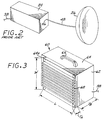
- Figure 2 depicts the implementation of a conventional prior radio frequency unit 24 and antenna 26, connected by the microwave feed 48, which utilizes the electronics approach of Figure 1.
- the radio frequency unit 24 typically has measurements of 30.5 by 30.5 by 30.5 cm [12 inches by 12 inches by 12 inches] and weighs about 15.88 kg [35 pounds].
- the antenna 26 is a cassegrain parabolic antenna having a dish diameter of about 30.5 cm [12 inches] or more and a weight of about 6.80 kg [15 pounds].
- Both components must be mounted at a location such that the antenna 26 may be aimed at a similar but remotely located terminal.
- the installer must find a way to mount the antenna 26 so that it is aligned with the antenna of the remote unit, and to mount the radio frequency unit 24 so that it is secure yet is within the range permitted by the length of the microwave feed 48.
- Other versions of the prior approach of Figure 2 are known wherein the parabolic antenna is affixed directly to the radio frequency unit, but such a combined approach remains awkward to handle and heavy.
- FIG 3 shows an integrated radio frequency unit/antenna in perspective view.
- Figure 4 illustrates a preferred form of the present invention in partially sectioned front elevational exterior view
- Figure 5 is an exploded side view of the preferred apparatus.
- An integrated radio frequency unit/antenna 60 includes a housing 62 having an exterior wall 64.
- a handle 65 extending from the housing 62 permits the radio frequency unit/antenna 60 to be easily carried.
- a microwave radio frequency transceiver electronics package 66 is fixed in the housing 62.
- the electronics package 66 includes the microwave transceiver 40, the controller 42, and the power supply 44.
- Part of the exterior wall 64 is formed as an integral flat antenna 68.
- the flat antenna 68 may be formed separately and attached to the wall 64, as illustrated, or it may be formed as part of the wall itself. That portion of the wall 64 which is not the antenna 68 may be made of any operable material, such as a metal or a plastic.
- a radome 70 in the form of a plastic sheet is mounted over the face of the flat antenna 68 to protect it.
- the flat antenna 68 is preferably a continuous transverse stub (CTS) antenna.
- CTS microwave antenna is known in the art and is described, for example, in US Patent 5,266,961, whose disclosure is incorporated by reference.
- the CTS antenna has a dielectric element with a first portion and a second portion extending generally transversely to the first portion.
- the second portion forms a transverse stub that protrudes from a first surface of the first portion.
- a first conductive element is disposed coextensively with the dielectric element along a second surface of the first portion.
- a second conductive element is disposed along the first surface of the dielectric element and is along transversely extending edgewalls formed by the second portion of the dielectric element. Further detail of construction are disclosed in the '961 patent.
- the CTS antenna has particular advantages when used in the present application.
- the CTS antenna is planar, small in lateral dimensions and thickness, and light in weight.
- the output signal of the CTS antenna may be steered slightly electronically.
- the radio frequency unit/antenna 60 must be aligned generally toward the remote unit with which communication is established. However, that alignment may be slightly disrupted due to weather or temperature effects on the mounting structure. In that case, the small deviation from proper alignment may be compensated for electronically to maintain a high signal strength aimed at the remote unit.
- the integrated radio frequency unit/antenna 60 has an antenna connection 46 and a microwave radio frequency feed cable 48 extending from the antenna connection 46 to the back side of the flat antenna 68.
- radio frequency feed 48 is at most 2.54-5.08 cm [1-2 inches] long and contained entirely within the housing 62. There is very little microwave attenuation as the signal passes through this short feed 48. The installer is only required to position and fix in place the single integrated radio frequency unit/antenna 60, and is not concerned with moving and positioning two units in a compatible manner.
- the inventors have developed a prototype design for the integrated radio frequency unit/antenna 60, shown in Figures 4-5, for operation at a microwave frequency of 37-40 GHz.
- the flat antenna has a width W of about 20.67 cm [10-1/2 inches], a length L of about 20.67 cm [10-1/2 inches], and a thickness T A of about 2.54 cm [1 inch].
- the remaining components, the microwave transceiver 40, controller 42, and power supply 44 fit into a housing having the same length and width, and a thickness T B of about 5.08 cm [2 inches].
- the total size of the housing and antenna package is about 30.5 cm [12 inches] by 30.5 cm [12 inches] by 7.6 cm [3 inches].
- the weight of the integrated radio frequency unit/antenna 60 is about 4.54 kg [10 pounds].
- FIG. 6 which is schematic and not drawn to scale, illustrates the mounting of a conventional radio frequency unit 80 and its antenna 82, connected by their microwave feed 84, on a mast 86. Also shown is an integrated radio frequency unit/antenna 60 of the invention.
- the integrated radio frequency unit/antenna 60 has a mounting bracket 88 attached to one of the exterior wall 64 other than the one to which the integrated flat antenna 68 is attached, and the mounting bracket permits straightforward adjustable attachment to the mast 86. It is apparent that the approach of the invention is much more convenient for installation and alignment than the conventional approach.
- the integrated radio frequency unit/antenna 60 can also be mounted in locations and places which are largely not usable with the conventional device. For example, the integrated radio frequency unit/antenna 60 is readily mounted to a window frame in much the same manner as a room air conditioner.
Landscapes
- Transceivers (AREA)
- Support Of Aerials (AREA)
- Waveguide Aerials (AREA)
- Aerials With Secondary Devices (AREA)
Applications Claiming Priority (2)
| Application Number | Priority Date | Filing Date | Title |
|---|---|---|---|
| US08/665,755 US6396443B1 (en) | 1996-06-18 | 1996-06-18 | Integrated flat antenna and radio frequency unit for point-to-point microwave radios |
| US665755 | 1996-06-18 |
Publications (1)
| Publication Number | Publication Date |
|---|---|
| EP0814538A1 true EP0814538A1 (de) | 1997-12-29 |
Family
ID=24671453
Family Applications (1)
| Application Number | Title | Priority Date | Filing Date |
|---|---|---|---|
| EP97109733A Withdrawn EP0814538A1 (de) | 1996-06-18 | 1997-06-14 | Integrierte flache Antenne und Funkgerät für Punkt-zu-Punkt Mikrowellen-Funkverbindungen |
Country Status (3)
| Country | Link |
|---|---|
| US (1) | US6396443B1 (de) |
| EP (1) | EP0814538A1 (de) |
| JP (1) | JPH10107674A (de) |
Cited By (5)
| Publication number | Priority date | Publication date | Assignee | Title |
|---|---|---|---|---|
| EP1158604A2 (de) * | 2000-05-26 | 2001-11-28 | Matsushita Electric Industrial Co., Ltd. | Antenne, Antennenanordnung und Funkgerät |
| WO2002027863A1 (en) * | 2000-09-29 | 2002-04-04 | British Telecommunications Public Limited Company | Antenna assembly |
| WO2005001987A1 (de) * | 2003-06-26 | 2005-01-06 | Kathrein-Werke Kg | Hf-verbindung für eine verbindung einer hf-komponente mit einer antenne |
| US6922174B2 (en) | 2003-06-26 | 2005-07-26 | Kathrein-Werke Kg | Mobile radio antenna for a base station |
| EP2403058A1 (de) * | 2010-06-29 | 2012-01-04 | Vodafone Holding GmbH | Befestigungsadapter für eine Richtfunkantenne |
Families Citing this family (5)
| Publication number | Priority date | Publication date | Assignee | Title |
|---|---|---|---|---|
| WO2002065577A2 (en) * | 2001-02-06 | 2002-08-22 | Harris Corporation | Antenna packaging and mounting assemblies and method |
| US20070265834A1 (en) * | 2001-09-06 | 2007-11-15 | Einat Melnick | In-context analysis |
| US20080221868A1 (en) * | 2005-09-05 | 2008-09-11 | Melnick Einat H | Digital universal language |
| US8750792B2 (en) | 2012-07-26 | 2014-06-10 | Remec Broadband Wireless, Llc | Transmitter for point-to-point radio system |
| EP3254334B1 (de) * | 2015-02-26 | 2023-11-22 | Huawei Technologies Co., Ltd. | Funkeinheitsgehäuse und basisstationsantennenmodul |
Citations (7)
| Publication number | Priority date | Publication date | Assignee | Title |
|---|---|---|---|---|
| US4876709A (en) * | 1988-09-08 | 1989-10-24 | Dynascan Corporation | Antenna for cordless telephone system |
| DE4128972A1 (de) * | 1991-08-31 | 1993-03-04 | Telefunken Systemtechnik | Funkgeraet fuer ein satelliten-kommunikationssystem |
| EP0570325A1 (de) * | 1992-05-15 | 1993-11-18 | State of Israel Ministry of Defence Raphael Armament Development Authority | Tragbares Übertragungsgerät |
| US5266961A (en) * | 1991-08-29 | 1993-11-30 | Hughes Aircraft Company | Continuous transverse stub element devices and methods of making same |
| EP0626764A1 (de) * | 1993-05-27 | 1994-11-30 | Nec Corporation | Tragbares Gerät für Satellitenkommunikation |
| US5400039A (en) * | 1991-12-27 | 1995-03-21 | Hitachi, Ltd. | Integrated multilayered microwave circuit |
| WO1995025387A1 (fr) * | 1994-03-17 | 1995-09-21 | Fujitsu Limited | Emetteur-recepteur a antenne |
Family Cites Families (2)
| Publication number | Priority date | Publication date | Assignee | Title |
|---|---|---|---|---|
| US5160936A (en) * | 1989-07-31 | 1992-11-03 | The Boeing Company | Multiband shared aperture array antenna system |
| FR2659501B1 (fr) * | 1990-03-09 | 1992-07-31 | Alcatel Espace | Systeme d'antenne imprimee active a haut rendement pour radar spatial agile. |
-
1996
- 1996-06-18 US US08/665,755 patent/US6396443B1/en not_active Expired - Lifetime
-
1997
- 1997-06-14 EP EP97109733A patent/EP0814538A1/de not_active Withdrawn
- 1997-06-18 JP JP9161227A patent/JPH10107674A/ja active Pending
Patent Citations (7)
| Publication number | Priority date | Publication date | Assignee | Title |
|---|---|---|---|---|
| US4876709A (en) * | 1988-09-08 | 1989-10-24 | Dynascan Corporation | Antenna for cordless telephone system |
| US5266961A (en) * | 1991-08-29 | 1993-11-30 | Hughes Aircraft Company | Continuous transverse stub element devices and methods of making same |
| DE4128972A1 (de) * | 1991-08-31 | 1993-03-04 | Telefunken Systemtechnik | Funkgeraet fuer ein satelliten-kommunikationssystem |
| US5400039A (en) * | 1991-12-27 | 1995-03-21 | Hitachi, Ltd. | Integrated multilayered microwave circuit |
| EP0570325A1 (de) * | 1992-05-15 | 1993-11-18 | State of Israel Ministry of Defence Raphael Armament Development Authority | Tragbares Übertragungsgerät |
| EP0626764A1 (de) * | 1993-05-27 | 1994-11-30 | Nec Corporation | Tragbares Gerät für Satellitenkommunikation |
| WO1995025387A1 (fr) * | 1994-03-17 | 1995-09-21 | Fujitsu Limited | Emetteur-recepteur a antenne |
Cited By (7)
| Publication number | Priority date | Publication date | Assignee | Title |
|---|---|---|---|---|
| EP1158604A2 (de) * | 2000-05-26 | 2001-11-28 | Matsushita Electric Industrial Co., Ltd. | Antenne, Antennenanordnung und Funkgerät |
| EP1158604B1 (de) * | 2000-05-26 | 2006-07-19 | Matsushita Electric Industrial Co., Ltd. | Antenne, Antennenanordnung und Funkgerät |
| WO2002027863A1 (en) * | 2000-09-29 | 2002-04-04 | British Telecommunications Public Limited Company | Antenna assembly |
| WO2005001987A1 (de) * | 2003-06-26 | 2005-01-06 | Kathrein-Werke Kg | Hf-verbindung für eine verbindung einer hf-komponente mit einer antenne |
| US6922174B2 (en) | 2003-06-26 | 2005-07-26 | Kathrein-Werke Kg | Mobile radio antenna for a base station |
| DE10328880B4 (de) * | 2003-06-26 | 2007-08-30 | Kathrein-Werke Kg | Mobilfunkantenne einer Basisstation |
| EP2403058A1 (de) * | 2010-06-29 | 2012-01-04 | Vodafone Holding GmbH | Befestigungsadapter für eine Richtfunkantenne |
Also Published As
| Publication number | Publication date |
|---|---|
| JPH10107674A (ja) | 1998-04-24 |
| US6396443B1 (en) | 2002-05-28 |
Similar Documents
| Publication | Publication Date | Title |
|---|---|---|
| US20110006956A1 (en) | Passive parabolic antenna, wireless communication system and method of boosting signal strength of a subscriber module antenna | |
| US20050024272A1 (en) | Parasitic element and PIFA antenna structure | |
| KR20010075231A (ko) | 용량성으로 튜닝된 광대역 안테나 구조 | |
| AU697888B2 (en) | Microwave transceiver/antenna system with adjustable mounting and alignment mechanism | |
| US6396443B1 (en) | Integrated flat antenna and radio frequency unit for point-to-point microwave radios | |
| US6608597B1 (en) | Dual-band glass-mounted antenna | |
| EP0858694B1 (de) | Kompakte richtfunkstrecke mit monolithisch integrierten mikrowellen-schaltungsmodulen | |
| US5945950A (en) | Stacked microstrip antenna for wireless communication | |
| US5864321A (en) | Microwave terrestrial radio with dovetail attachment and reference plane | |
| EP0458592B1 (de) | Passives Antennensystem für zellulares Telefon | |
| KR100461767B1 (ko) | 케이유밴드용 마이크로스트립 패치 어레이 안테나 | |
| AU737726B2 (en) | Compact microwave terrestrial radio utilizing monolithic microwave integrated circuits | |
| MXPA98003538A (en) | Compact microwave terrestrial radio utilizing monolithic microwave integrated circuits | |
| JPH01165206A (ja) | 空中線 | |
| JPS62234404A (ja) | 無線機用アンテナ | |
| EP1407509A1 (de) | Antennenadapter für eine hf-einrichtung | |
| JPH0576106U (ja) | Gpsとホイップ型の複合アンテナ | |
| JPH06284021A (ja) | 無線設備 | |
| KR20010004076A (ko) | 무지향성의 안테나 | |
| JPS63191402A (ja) | 建築物用高周波アンテナ装置 | |
| JP2000209025A (ja) | 無線機 | |
| TH28316B (th) | อุปกรณ์การสื่อสารทางวิทยุชนิดเคลื่อนย้ายได้ | |
| KR19990054735A (ko) | 씨티-2 기지국용 패치 안테나 |
Legal Events
| Date | Code | Title | Description |
|---|---|---|---|
| PUAI | Public reference made under article 153(3) epc to a published international application that has entered the european phase |
Free format text: ORIGINAL CODE: 0009012 |
|
| AK | Designated contracting states |
Kind code of ref document: A1 Designated state(s): DE DK FI FR GB IT SE |
|
| 17P | Request for examination filed |
Effective date: 19980617 |
|
| AKX | Designation fees paid |
Free format text: AT BE CH DE DK ES FI FR GB GR IE IT LI LU MC NL PT SE |
|
| R17P | Request for examination filed (corrected) |
Effective date: 19980613 |
|
| RBV | Designated contracting states (corrected) |
Designated state(s): DE DK FI FR GB IT SE |
|
| RAP1 | Party data changed (applicant data changed or rights of an application transferred) |
Owner name: RAYTHEON COMPANY |
|
| 17Q | First examination report despatched |
Effective date: 19990507 |
|
| STAA | Information on the status of an ep patent application or granted ep patent |
Free format text: STATUS: THE APPLICATION HAS BEEN WITHDRAWN |
|
| 18W | Application withdrawn |
Withdrawal date: 20011013 |