EP0814521A2 - Verfahren zur Herstellung von poröser Beschichtung, Elektrodenplatte für Sekundärbatterie mit nichtwasserigem Elektrolyt sowie Herstellungsverfahren und Folie zum Abtrennen von aktiver Materialschicht - Google Patents
Verfahren zur Herstellung von poröser Beschichtung, Elektrodenplatte für Sekundärbatterie mit nichtwasserigem Elektrolyt sowie Herstellungsverfahren und Folie zum Abtrennen von aktiver Materialschicht Download PDFInfo
- Publication number
- EP0814521A2 EP0814521A2 EP97304213A EP97304213A EP0814521A2 EP 0814521 A2 EP0814521 A2 EP 0814521A2 EP 97304213 A EP97304213 A EP 97304213A EP 97304213 A EP97304213 A EP 97304213A EP 0814521 A2 EP0814521 A2 EP 0814521A2
- Authority
- EP
- European Patent Office
- Prior art keywords
- active material
- liquid material
- material layer
- coating layer
- peeling
- Prior art date
- Legal status (The legal status is an assumption and is not a legal conclusion. Google has not performed a legal analysis and makes no representation as to the accuracy of the status listed.)
- Granted
Links
Images


Classifications
-
- H—ELECTRICITY
- H01—ELECTRIC ELEMENTS
- H01M—PROCESSES OR MEANS, e.g. BATTERIES, FOR THE DIRECT CONVERSION OF CHEMICAL ENERGY INTO ELECTRICAL ENERGY
- H01M4/00—Electrodes
- H01M4/02—Electrodes composed of, or comprising, active material
- H01M4/04—Processes of manufacture in general
- H01M4/0402—Methods of deposition of the material
- H01M4/0416—Methods of deposition of the material involving impregnation with a solution, dispersion, paste or dry powder
-
- B—PERFORMING OPERATIONS; TRANSPORTING
- B44—DECORATIVE ARTS
- B44C—PRODUCING DECORATIVE EFFECTS; MOSAICS; TARSIA WORK; PAPERHANGING
- B44C1/00—Processes, not specifically provided for elsewhere, for producing decorative surface effects
- B44C1/16—Processes, not specifically provided for elsewhere, for producing decorative surface effects for applying transfer pictures or the like
- B44C1/165—Processes, not specifically provided for elsewhere, for producing decorative surface effects for applying transfer pictures or the like for decalcomanias; sheet material therefor
- B44C1/17—Dry transfer
- B44C1/1712—Decalcomanias applied under heat and pressure, e.g. provided with a heat activable adhesive
- B44C1/1716—Decalcomanias provided with a particular decorative layer, e.g. specially adapted to allow the formation of a metallic or dyestuff layer on a substrate unsuitable for direct deposition
-
- B—PERFORMING OPERATIONS; TRANSPORTING
- B44—DECORATIVE ARTS
- B44C—PRODUCING DECORATIVE EFFECTS; MOSAICS; TARSIA WORK; PAPERHANGING
- B44C5/00—Processes for producing special ornamental bodies
- B44C5/04—Ornamental plaques, e.g. decorative panels, decorative veneers
- B44C5/0469—Ornamental plaques, e.g. decorative panels, decorative veneers comprising a decorative sheet and a core formed by one or more resin impregnated sheets of paper
-
- H—ELECTRICITY
- H01—ELECTRIC ELEMENTS
- H01M—PROCESSES OR MEANS, e.g. BATTERIES, FOR THE DIRECT CONVERSION OF CHEMICAL ENERGY INTO ELECTRICAL ENERGY
- H01M4/00—Electrodes
- H01M4/02—Electrodes composed of, or comprising, active material
-
- H—ELECTRICITY
- H01—ELECTRIC ELEMENTS
- H01M—PROCESSES OR MEANS, e.g. BATTERIES, FOR THE DIRECT CONVERSION OF CHEMICAL ENERGY INTO ELECTRICAL ENERGY
- H01M4/00—Electrodes
- H01M4/02—Electrodes composed of, or comprising, active material
- H01M4/04—Processes of manufacture in general
-
- H—ELECTRICITY
- H01—ELECTRIC ELEMENTS
- H01M—PROCESSES OR MEANS, e.g. BATTERIES, FOR THE DIRECT CONVERSION OF CHEMICAL ENERGY INTO ELECTRICAL ENERGY
- H01M4/00—Electrodes
- H01M4/02—Electrodes composed of, or comprising, active material
- H01M4/04—Processes of manufacture in general
- H01M4/0402—Methods of deposition of the material
- H01M4/0404—Methods of deposition of the material by coating on electrode collectors
-
- H—ELECTRICITY
- H01—ELECTRIC ELEMENTS
- H01M—PROCESSES OR MEANS, e.g. BATTERIES, FOR THE DIRECT CONVERSION OF CHEMICAL ENERGY INTO ELECTRICAL ENERGY
- H01M4/00—Electrodes
- H01M4/02—Electrodes composed of, or comprising, active material
- H01M4/04—Processes of manufacture in general
- H01M4/043—Processes of manufacture in general involving compressing or compaction
-
- H—ELECTRICITY
- H01—ELECTRIC ELEMENTS
- H01M—PROCESSES OR MEANS, e.g. BATTERIES, FOR THE DIRECT CONVERSION OF CHEMICAL ENERGY INTO ELECTRICAL ENERGY
- H01M4/00—Electrodes
- H01M4/02—Electrodes composed of, or comprising, active material
- H01M4/04—Processes of manufacture in general
- H01M4/0483—Processes of manufacture in general by methods including the handling of a melt
-
- Y—GENERAL TAGGING OF NEW TECHNOLOGICAL DEVELOPMENTS; GENERAL TAGGING OF CROSS-SECTIONAL TECHNOLOGIES SPANNING OVER SEVERAL SECTIONS OF THE IPC; TECHNICAL SUBJECTS COVERED BY FORMER USPC CROSS-REFERENCE ART COLLECTIONS [XRACs] AND DIGESTS
- Y02—TECHNOLOGIES OR APPLICATIONS FOR MITIGATION OR ADAPTATION AGAINST CLIMATE CHANGE
- Y02E—REDUCTION OF GREENHOUSE GAS [GHG] EMISSIONS, RELATED TO ENERGY GENERATION, TRANSMISSION OR DISTRIBUTION
- Y02E60/00—Enabling technologies; Technologies with a potential or indirect contribution to GHG emissions mitigation
- Y02E60/10—Energy storage using batteries
-
- Y—GENERAL TAGGING OF NEW TECHNOLOGICAL DEVELOPMENTS; GENERAL TAGGING OF CROSS-SECTIONAL TECHNOLOGIES SPANNING OVER SEVERAL SECTIONS OF THE IPC; TECHNICAL SUBJECTS COVERED BY FORMER USPC CROSS-REFERENCE ART COLLECTIONS [XRACs] AND DIGESTS
- Y10—TECHNICAL SUBJECTS COVERED BY FORMER USPC
- Y10T—TECHNICAL SUBJECTS COVERED BY FORMER US CLASSIFICATION
- Y10T29/00—Metal working
- Y10T29/49—Method of mechanical manufacture
- Y10T29/49002—Electrical device making
- Y10T29/49108—Electric battery cell making
- Y10T29/49115—Electric battery cell making including coating or impregnating
Definitions
- the present invention relates to a process for producing a porous coating layer, especially a porous coating layer having a prescribed pattern, which is suitable for an active material layer of an electrode plate for a secondary battery with a nonaqueous electrolyte; a process for producing an electrode plate for a secondary battery with a nonaqueous electrolyte, in which the above-mentioned process for producing the porous coating layer is utilized; the electrode plate for a secondary battery with a nonaqueous electrolyte obtained by the above-mentioned process; and a'sheet for peeling an active material layer, especially a sheet for peeling an active material layer used in the above-mentioned process for producing the electrode plate for a secondary battery with a nonaqueous electrolyte.
- FIG. 22 shows a structure of a cylindrical shape-lithium ion secondary battery as generally used.
- the cylindrical shape-lithium ion secondary battery 34 as generally used has an external; appearance given by a metallic column.
- the battery 34 has a positive electrode 35 at its one end, and a negative electrode 36 at its another end.
- the battery 34 has an inside structure in which a positive electrode plate 37 generally made of lithium compound such as LiCoO 2 , a negative electrode plate 38 made of carbonaceous material and a separator 39 arranged between the positive electrode plate 37 and the negative electrode plate 38 for preventing a short circuit of them are wound in a piled up state.
- the battery is filled with a nonaqueous electrolyte 40 as an electrolyte, which is obtained by dissolving lithium salts into an organic solvent, since lithium contained in the positive electrode plate 37 has a character of reacting with water.
- Terminals for introducing an electric current i.e., a positive cable terminal 41 and a negative cable terminal 42 are connected to the above-mentioned electrode.
- 10456/1988 and 285262/1991 disclose a process for producing a positive electrode plate, which comprises the steps of: dispersing and dissolving an active material powder for a positive electrode plate, which comprises metallic oxides, sulfides, halides and the like, conductive agents and a binder into a suitable wetting agent (hereinafter referred to as the "solvent") to prepare an active material coating composition in the form of paste, and applying the above-mentioned active material coating composition on the surface of a collector as a substrate, made of a metallic foil to prepare an active material layer for a positive electrode plate (hereinafter referred to as the "positive electrode coating layer").
- an active material powder for a positive electrode plate which comprises metallic oxides, sulfides, halides and the like, conductive agents and a binder into a suitable wetting agent (hereinafter referred to as the "solvent") to prepare an active material coating composition in the form of paste, and applying the above-mentioned active material coating composition on the surface
- An active material layer for a negative electrode plate obtained by applying the above-mentioned active material coating composition on the substrate is hereinafter referred to as the "negative electrode coating layer". Both of the positive and negative electrode coating layers are simply referred to as the "coating layer”.
- fluororesins such as polyvinylidene fluoride; silicone-acrylic copolymer; styrene-butadiene copolymer, and the like.
- a negative electrode plate can be obtained by adding a binder and a suitable wetting agent (i.e., a solvent) to an active material such as carbon for a negative electrode plate to prepare an active material coating composition in the form of paste, and applying the thus prepared active material coating composition to a collector made of a metallic foil.
- a binder and a suitable wetting agent i.e., a solvent
- the binder for preparing the active material coating composition for the above-described coating type electrode plate is required to be chemically stable against the nonaqueous electrolyte, insoluble in the electrolyte, and soluble in a certain solvent to be able to be applied to the surface of the substrate in the form of thin film.
- the coating layer obtained by applying the coating composition, and drying same is required to be so flexible that there is no occurrence of peeling, chipping and cracks in the coating layer during the assembling step of the battery, and to be excellent in adhesivity to the collector made of a metallic foil.
- the electrode plate has non-coated portions on the basis of a prescribed pattern determined when making a plan for a battery.
- FIG. 5 is a plan view of the electrode plate.
- FIG. 23 is a plan view of a original sheet for a plurality of electrode plates. The original sheet has longitudinal non-coated portions along the both longitudinal edges of the original sheet and lateral non-coated portions 4 which cross the above-mentioned longitudinal non-coated portions at right angles.
- a process for forming a pattern of the non-coated portion there have been a process of mechanically controlling a coating head during applying the coating composition for an electrode plate onto the collector, to directly form each pattern of the coated portion (i.e., a portion in which the coating layer exists) and the non-coated portion, and another process of peeling the prescribed portion of the coating layer prepared by applying the coating composition for the electrode plate onto the collector and drying same, by means of a mechanical means, for example, a spatula or the like, to form the non-coated portion.
- a mechanical means for example, a spatula or the like
- the process of mechanically controlling the coating head has a problem of insufficient mechanical accuracy, thus making it hard to form a prescribed pattern at a high velocity while maintaining a proper measurement accuracy of the pattern, and leading to non-uniform thickness of the coating layer.
- the process of partially peeling the dried coating layer requires a long period of time for the peeling, and has problems that a proper measurement accuracy of the pattern cannot be maintained, and production of powder at peeled edges of the coating layer on the basis of the pattern may be caused during or after the peeling step.
- the first object of the present invention is to provide a process for producing a porous coating layer having a prescribed pattern, which permits to keep the thickness of the coating layer uniform and to keep the prescribed pattern sharp.
- the second object of the present invention is to provide a process for producing an electrode plate having a prescribed pattern for a secondary battery with a nonaqueous electrolyte, which permits to keep the thickness of the active material layer uniform and to keep the prescribed pattern sharp.
- the third object of the present invention is to provide an electrode plate having a prescribed pattern for a secondary battery with a nonaqueous electrolyte, in which the thickness of the active material layer is kept uniform and the prescribed pattern is kept sharp.
- the fourth object of the present invention is to provide a sheet for peeling an active material layer which permits to effectively form a prescribed sharp pattern in the above-described process for producing the porous coating layer and the above-described process for producing the electrode plate for a secondary battery with a nonaqueous electrolyte.
- the present invention has been made on the basis of the above-mentioned findings.
- the process thereof for producing a porous coating layer having a prescribed pattern which comprises the steps of:
- the portion of the coating layer, which is impregnated with the liquid material in the form of a pattern can be peeled after the solidification of the liquid material together with the porous sheet stuck on the portion based on the pattern, with the result that all the portions of the coating layer to be removed on the basis of the pattern can be removed by carrying out a single peeling step without leaving the portions to be removed of the coating layer non-peeled. Since the porous sheet is placed, prior to the solidification of the liquid material, namely in the state of liquid, on the portion of the coating layer, which is impregnated with the liquid material, cracks do not easily tend to be produced on the portion of the coating layer to be removed.
- the portion of the coating layer, which has been impregnated with the liquid material is preferably peeled together with said porous sheet by peeling the porous sheet from the substrate while imparting tension to said porous sheet not so as to be loosened, in said step of partially exposing the surface of the substrate based on the prescribed pattern.
- Said liquid material preferably comprise material which is solid at a room temperature, and can be liquefied by heat.
- the step of integrally bonding the porous sheet with the coating layer can be modified on the basis of various manners, thus making it possible to apply this process not only to a continuous production line but also to an intermittent production line.
- Said porous sheet in the item (31) may comprise any one of polyester mesh, metallic mesh, cloth, paper and a nonwoven fabric cloth.
- an electrode plate for a secondary battery with a nonaqueous electrolyte can be produced by carrying out a process comprising the steps of:
- a sheet thereof for peeling an active material layer comprises a porous sheet and thermoplastic resin impregnated in said porous sheet.
- the present invention may be classified into the first group as the generic group in which a means for peeling a portion of an active material layer, which is impregnated with liquid material is not defined, the second group characterized in that a peeling sheet impregnated with thermoplastic resin is used as such a peeling means, and the peeling sheet is heat-pressed on a portion to be removed of the active material layer, the third group characterized in that a formed body made of thermoplastic resin which is solid at a room temperature, is used as the peeling means, and the fourth group characterized in that a porous sheet is used as the peeling means.
- a process of the present invention in the first group, for producing a porous coating layer is characterized by comprising the steps of impregnating a porous coating layer formed on a substrate with liquid material having a larger cohesion after solidification thereof than that of said coating layer based on a prescribed pattern; solidifying said liquid material to form a solidified material; and peeling a portion of said coating layer, which has been impregnated with said solidified material, to expose partially a surface of said substrate based on said prescribed pattern.
- An typical example in which the process of the present invention is utilized in the production of an electrode plate for a secondary battery with a nonaqueous electrolyte will be described below.
- the application of the process of the present invention is not limited to the application thereof to the production of such an electrode plate for a secondary battery with a nonaqueous electrolyte.
- the present inventors have carried out extensive studies of a process for forming an active material coating layer based on a prescribed pattern in the production of an electrode plate for a secondary battery with a nonaqueous electrolyte. In the above-mentioned studies, they directed their attention to the following facts:
- liquid material tends to be easily permeate through the active material layer in the width direction due to the porosity thereof.
- the impregnated portion of the active material layer is remarkably different from the non-impregnated portion thereof in physical strength, and as a result that only the impregnated portion of the active material layer can easily be peeled from the collector, thus exposing the surface of the collector to be exposed on the basis of the pattern without leaving the portion to be removed of the active material layer non-peeled.
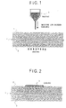
- a solidifying agent 3 as liquid material such as wax is melted by heat, and the thus melted solidifying agent is dropped on an active material coating layer 2 formed on the surface of a collector 1.
- the dropped solidifying agent 3 permeates through the active material coating layer 2, and cavities in the active material coating layer 2 are filled with the solidifying agent 3.
- the collector 1 and/or the active material coating layer 2 may be heated in order to prevent the liquefied solidifying agent 3 from being solidified before the solidifying agent 3 reaches the surface of the collector 1.
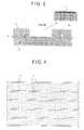
- FIG. 2 shows a state in which the solidifying agent 3 permeates through the active material coating layer 2, and it is solidified by the cooling.
- a portion of the active material coating layer 2, through which the solidifying agent 3 permeates has a excessively higher density than that of the other portion, and cohesion of the former is higher than that of the latter.
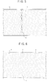
- FIG. 3 shows a state in which the portion of the active material coating layer 2, which is impregnated with the solidifying agent is peeled.
- the portion 2a of the active material coating layer 2, which is impregnated with the solidifying agent 3 has a higher density and a higher cohesion through the impregnation with the solidifying agent 3, and the cohesion of the portion is excessively higher than that of the adjacent other portion of the active material coating layer 2, which is not impregnated with the solidifying agent 3, as described above.
- the portion 2a of the active material coating layer 2, which is impregnated with the solidifying agent is peeled by an appropriate means, can be peeled in a state that the active material coating layer 2 is surrounded by the solidifying agent 3, and the surface of the collector can be exposed on the basis of the sharp pattern after the peeling of the portion 2a.
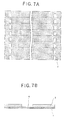
- a shape of the pattern formed by the process of the present invention can optionally be selected. Examples of the pattern are shown in FIGS. 4 to 6.
- FIGS. 4 to 6 4 is a peeled portion and 5 is a non-peeled portion.
- G is a peeled portion to which a terminal is to be connected.
- a solidifying agent 3 material which is solid at a room temperature, and can be liquefied by heat, for example, at least one of thermoplastic resin, organic or inorganic wax and a low melting point-metal.
- the solidifying agent 3 preferably has a melting point of from 20°C to 250°C, and more preferably of form 60°C to 150°C.
- the melting point of the solidifying agent 3 is excessively low, it softens at a room temperature, leading to hard handling thereof and a poor productivity of the electrode plate.
- the melting point thereof is excessively high, on the other hand, there occurs uneconomical problem in energy.
- the solidifying agent 3 preferably has viscosity of from 10 to 50,000 cP when the melting thereof, and more preferably of from 300 to 6,000 cP.
- the viscosity of the solidifying agent 3 is excessively high, the solidifying agent 3 tends to not permeate easily into fine cavities of the active material coating layer 2, leading to a poor productivity of the electrode plate.
- the viscosity thereof is excessively low, the solidifying agent 3 in a molten state tends to spread over in the inside of the active material coating layer 2 in a direction along a plane parallel to the surface thereof by the capillary phenomenon, thus making it impossible to form a sharp pattern.
- thermoplastic resin such as polyolefin resin such as polyethylene, polypropylene and the like; polyvinyl chloride resin; polystyrene; polyvinyl acetate resin; ethylene-vinyl acetate copolymer; ethylene-vinyl chloride copolymer; and the like, (2) low molecular weight polyethylene, (3) low molecular weight polypropylene, (4) copolymer thereof, (5) synthetic wax such as micro-crystalline wax, polyethylene wax oxide, and the mixture thereof, (6) natural wax such as carnauba wax, and (7) derivative and mixture thereof.
- thermoplastic resin such as polyolefin resin such as polyethylene, polypropylene and the like
- polystyrene polyvinyl acetate resin
- ethylene-vinyl acetate copolymer ethylene-vinyl chloride copolymer
- ethylene-vinyl chloride copolymer ethylene-vinyl chloride copolymer
- synthetic wax such as micro-crystalline wax, poly
- a solidifying agent 3 there may be used material which can transform from the liquid phase into the solid phase through a chemical reaction, for example, polymerization liquid material and cross-linking liquid material.
- polymerization liquid material and cross-linking liquid material there may be used polymerization liquid material and cross-linking liquid material used in a printing ink or a coating composition which have properties such as a thermosetting property, a catalytic-setting property, a setting property at a room temperature, a electron beam-setting property and an ultraviolet-setting property. Solidification of such kind of solidifying agent 3 may be carried out by heat, catalyst, the addition of a cross-linking agent, radiation of electron beam or ultraviolet.
- the solidifying agent 3 When the coating layer 2 is impregnated with the above-mentioned solidifying agent 3, it is necessary for the solidifying agent 3 to permeate through fine cavities in the coating layer 2 so as to reach the surface of the collector 1. If the liquefied solidifying agent 3 is solidified before it reaches the surface of the collector 1, a portion to be removed of the coating layer 2 may be left non-peeled even when the coating layer 2 impregnated with the solidifying agent 3 is peeled from the collector 1.
- At least one of the collector 1 and the coating layer 2 may be heated to an appropriate temperature to delay the solidification of the solidifying agent 3, or the solidifying agent 3 having a low viscosity may be selected to increase the permeating velocity of thereof, or the solidifying agent 3 may be kept at a sufficiently high temperature to delay the solidification thereof.
- the copper foil tends to be oxidized to produce a reddish surface thereof upon heating it to the temperature of at least 140°C.
- the coating layer 2 is heated by means of a hot plate during applying (dropping) the solidifying agent 3, the increase in temperature of the hot plate to at least 140°C does not however cause the occurrence of the above-mentioned problem of oxidization of the copper foil, since the both surfaces of the copper foil are coated with the coating layers 2 and the heating is conducted from the side of the surface of the coating layer 2 onto which the solidifying agent 3 has been applied.
- the coating layer 2 by means of extreme infrared radiation or the like from the side of the surface on which the pattern is to be formed, to keep the exposed back surface of the collector 1 at a temperature of under 140°C, in order to prevent the exposed surface of the copper foil from being oxidized.
- a method of permeating the solidifying agent 3 through the coating layer 2 on the basis of the pattern there are many methods, i.e., a method of applying the solidifying agent 3 in the molten state onto the coating layer 2, a method of arranging a solid body made of the solidifying agent 3 on the basis of the pattern on the coating layer 2 and heating the coating layer 2 to melt the solidifying agent 3 which is in contact with the coating layer 2 so as to impregnate the coating layer 2 with the solidifying agent 3, a method of previously preparing a stencil having a prescribed pattern, and applying the solidifying agent 3 onto the coating layer 2 with the use of the stencil to impregnate the coating layer 2 with the solidifying agent 3, and the like.
- the solidifying agent 3 in the molten state is applied onto the coating layer 2, it is possible to use a conventional coating apparatus such as a dispenser, a gravure roll, a die head and the like.
- a conventional coating apparatus such as a dispenser, a gravure roll, a die head and the like.
- the dropping apparatus for the solidifying agent as shown in FIG. 1 is secured to an x-axis and y-axis plotter type driving apparatus, it is possible to drop the solidifying agent 3 based on the prescribed pattern in accordance with the movement of the x-axis and y-axis plotter.
- the solidifying agent 3 is dropped to draw the above-mentioned prescribed character, figure or pattern.
- the portion of the coating layer 2 impregnated with the solidifying agent is normally stuck to the collector 1 in a smaller strength, and this portion can easily be peeled.
- tension may be imparted to the collector 1 to lift up the portion of the coating layer 2 impregnated with the solidifying agent from the collector 1 so as to perform the peeling thereof, or it may be peeled from the collector 1 by means of a spatula, or it may be peeled with the use of an adhesive tape, or it may be peeled from the collector 1 by the blowing of air.
- the impregnation of the coating layer with the solidifying agent 3 may be carried out before or after the pressing step described later of the coating layer 2.
- the secondary battery with a noaqueous electrolyte may be exemplified by a lithium secondary battery, and is characterized in the use of the nonaqueous organic solvent as an electrolyte.
- the coating layer i.e., the active material coating layer
- the nonaqueous organic solvent is used as an electrolyte.
- charge and discharge can be performed by interchange of electrons during the movement of a lithium ion between the positive electrode and the negative electrode.
- the coating layer containing the active material, of which the electrode plate for a secondary battery with a nonaqueous electrolyte of the present invention can be formed by the coating composition for the electrode which comprises active material and a binder.
- an active material for the positive electrode used in the present invention there may be used at least one kind of lithium oxides such as LiCoO 2 , LiMn 2 O 4 and the like, and chalcogen compounds such as TiS 2 , MnO 2 , MoO 3 , V 2 O 5 and the like.
- an active material for the negative electrode it is preferable to use metallic lithium, lithium alloy and carbonacious material such as graphite, carbon black, acetylene or the like.
- metallic lithium, lithium alloy and carbonacious material such as graphite, carbon black, acetylene or the like.
- the carbonacious material is used as the active material for the negative electrode, it is possible to obtain a lithium secondary battery having a high discharge voltage of about 4 volt. It is preferable to disperse uniformly these active materials in the coating layer as formed. For this reason, it is preferable to use powder of the active material having a particle size of from 1 to 100 ⁇ m and an average particle size of about 10 ⁇ m.
- thermoplastic resin i.e., polyester resin, polyamide resin, polyacrylic acid-ester resin, polycarbonate resin, polyurethane resin, cellulose resin, polyolefin resin, polyvinyl resin, fluororesin and polyimide resin.
- thermoplastic resin i.e., polyester resin, polyamide resin, polyacrylic acid-ester resin, polycarbonate resin, polyurethane resin, cellulose resin, polyolefin resin, polyvinyl resin, fluororesin and polyimide resin.
- compounds in which reactive functional group is introduced i.e., acrylate monomer or oligomer
- the acrylate monomer and the oligomer may be used alone or in combination.
- the coating layer containing the active material, of which the electrode plate for a secondary battery with a nonaqueous electrolyte of the present invention can be prepared in the following manner.
- the coating composition to be applied onto the collector is prepared with the use of the above-described materials. More specifically, the binder and the powdery active material, which are properly selected from the above-mentioned materials, are kneaded or dissolved in a state of dispersion with the use of an appropriate dispersing agent to prepare the coating composition for the electrode plate.
- the thus prepared coating composition is applied on the collector.
- a coating method a conventional coating method such as a gravure coating method, a die coating or a slide coating may be used.
- the coating composition is dried by carrying out a drying step to prepare a coating layer having a prescribed thickness.
- a metallic foil such as for example an aluminum foil, a copper foil or the like.
- Such a metallic foil preferably has a thickness of from about 10 ⁇ m to about 30 ⁇ m.
- the binder and the powdery active material which are appropriately selected from the above-described materials, are added to a dispersing medium comprising an organic solvent such as toluene, and a conductive agent is added to the dispersing medium, as an occasion demands, to prepare a mixture.
- a dispersing medium comprising an organic solvent such as toluene
- a conductive agent is added to the dispersing medium, as an occasion demands, to prepare a mixture.
- the thus prepared mixture is subjected to a mixing and dispersing process with the use of the conventional dispersing apparatus such as a homogenizer, a ball mill, a sand mill, a roll mill and the like.
- the same mixing ratio of the binder and the active material as the conventional mixing ratio thereof.
- the mixing ratio of the binder : the active material 2:8 through 1:9.
- carbonacious material such as graphite, carbon black, acetylene black or the like.
- the thus prepared coating composition for the electrode plate, containing the active material is applied on the collector made of a metallic foil such as an aluminum foil, a copper foil and the like with the use of a gravure coater, a gravure reverse coater, a die coater or the like, and then dried.
- the applying step and the drying step are carried out several times to prepare a coating layer having the thickness of from 10 to 200 ⁇ m, preferably offrom 50 to 170 ⁇ m.
- the coating layer obtained by carrying out the above-mentioned applying and drying steps is preferably subjected to a press treatment with the use of a metallic roll, a heating roll, a sheet pressing machine or the like, to prepare the electrode plate of the present invention, in order to improve homogeneousness of the coating layer.
- the pressing condition of from 500kgf/cm 2 to 7,500kgf/cm 2 , more preferably of from 3,000kgf/cm 2 to 5,000kgf/cm 2 may be applied to the above-described press treatment. With a pressing force of under 500kgf/cm 2 , the homogeneousness of the coating layer may not sufficiently be improved. With a pressing force of over 7,500kgf/cm 2 , the electrode plate itself including the collector may be broken, thus causing an unfavorable problem.
- the secondary battery is produced with the use of the electrode plate of the present invention, which has been prepared in the above-described manner, it is preferable to apply a heating treatment and a decompression treatment to the electrode plate prior to the assembling step of the secondary battery, in order to remove moisture in the coating layer of the electrode plate, which contains the active material.
- the process of the present invention for producing a porous coating layer is applied to the electrode plate prepared in the above-described manner.
- the lithium secondary battery is produced with the use of the thus prepared electrode plates, as positive and negative plates, of the present invention for a secondary battery with a nonaqueous electrolyte
- a nonaqueous electrolyte which is obtained by dissolving lithium salts as solute into an organic solvent.
- cyclic esters there may be used, as an organic solvent, cyclic esters, chain esters, cyclic ethers, chain ethers or the like.
- the cyclic esters may be exemplified by propylene carbonate, butylene carbonate, ⁇ -buthyrolactone, vinylene carbonate, 2-methyl- ⁇ -buthyrolactone, acetyl- ⁇ -buthyrolactone and ⁇ -valerolactone.
- the chain esters may be exemplified by dimethyl carbonate, diethyl carbonate, dibutyl carbonate, dipropyl carbonate, methyl ethyl carbonate, methyl butyl carbonate, methyl propyl carbonate, ethyl butyl carbonate, ethyl propyl carbonate, butyl propyl carbonate, propionic acid alkyl ester, malonic acid dialkyl ester and acetic acid alkyl ester.
- the cyclic ethers may be exemplified by tetrahydrofuran, alkyltetrahydrofuran, dialkyldialkyltetrahydrofuran, alkoxytetrahydrofuran, dialkoxytetrahydrofuran, 1,3-dioxolan, alkyl-1,3-dioxolan and 1,4-dioxolan.
- the chain ethers may be exemplified by 1,2-dimethoxyethane, 1,2-diethoxyethane, diethyl ether, ethylene glycol dialkylether, diethylene glycol dialkylether, triethylene glycol dialkylether and tetraethylene glycol dialkylether.
- lithium salts as solute forming the nonaqueous electrolyte in cooperation with the above-mentioned organic solvent, there may be used inorganic lithium salt such as LiClO 4 , LiBF 4 , LiPF 6 , LiAsF 6 , LiCl, LiBr or the like, or organic lithium salt such as LiB(C 6 H 5 ) 4 , LiN(SO 2 CF 3 ) 2 , LiC(SO 2 CF 3 ) 3 , LiOSO 2 CF 3 , LiOSO 2 C 2 F 5 , LiOSO 2 C 3 F 7 , LiOSO 2 C 4 F 9 , LiOSO 2 C 5 F 11 , LiOSO 2 C 6 F 13 , LiOSO 2 C 7 F 15 , or the like.
- inorganic lithium salt such as LiClO 4 , LiBF 4 , LiPF 6 , LiAsF 6 , LiCl, LiBr or the like
- organic lithium salt such as LiB(C 6 H 5 ) 4
- process of the present invention for producing porous coating layer is described to be applied to the production of the electrode plate for a secondary battery with a nonaqueous electrolyte
- the application of the process of the present invention is not limited only to the above-described application, and the process of the present invention can also be applied for the other object.
- the above-mentioned other object may be exemplified by the production of a substrate for a plasma-display panel.
- a substrate for a plasma-display panel For example, in a back surface plate of the plasma-display panel, an electrode (generally made of gold) is formed on the surface of a substrate made of glass through a primer layer.
- the primer layer is required to be formed by the coating method on an inside region of the surface of the glass substrate, which is apart from the periphery thereof by about 5mm, in order to prevent the peripheral portion from being unclean.
- the above-mentioned primer layer can be formed, for example, by applying paste which comprises frit of lead glass of 80 wt.%, a resin binder of 1 wt.% such as ethylcellulose and the balance being a solvent, and has viscosity of about 80,000 cP onto the surface of the substrate and drying and sintering same.
- the process of the present invention is utilized in the production of the above-mentioned plasma-display panel, it is possible to form the primer layer on the glass substrate on the basis of the precise pattern by applying the paste, i.e., the coating composition for the primer layer on the entire surface of the glass substrate and drying same, then peeling the peripheral portion of the primer layer having a width of about 5 mm to remove same from the glass substrate, and then sintering the glass substrate having the primer layer on the basi of the precise pattern.
- the paste i.e., the coating composition for the primer layer on the entire surface of the glass substrate and drying same
- the electrode plate of the present invention in the second group may be composed either of an original sheet having a series of plural plates as shown in FIG. 7(a), or of a single plate which is obtained by cutting the original sheet along lateral lines as shown in FIG. 7(a).
- a terminal 7 is connected to a portion of the surface of the collector, which is exposed on the basis of the prescribed pattern.
- the electrode plate in which the active material layer is partially removed on the basis of the prescribed pattern.
- the active material layer 2 which comprises active material and a binder is formed on a collector 1.
- a peeling sheet 8 impregnated with thermoplastic resin is placed on the surface of the active material layer 2.
- the peeling sheet 8 suffices to have an area larger than a region of the active material layer 2 to be removed, and may have either an area covering the entire active material layer 2, or an area covering only the region of active material layer to be removed.
- a pressure heating body 9 is pressed on the surface of the above-mentioned peeling sheet 8 as shown in FIG. 10.
- the pressure heating body 9 is composed of a metallic body which has a built-in heater and permits a temperature control thereof.
- the pressure heating body 9 has substantially the same bottom shape as the region of the active material layer 2 to be removed.
- thermoplastic resin with which the peeling sheet is impregnated is melted and permeates through the porous active material layer 2 by pressing the pressure heating body 9 on the peeling sheet 8 to heat the thermoplastic resin as shown in FIG. 10, or heating the thermoplastic resin from the side of the collector 1 as shown in bold arrows as shown in FIG. 10.
- the pressure heating body 9 is lifted up from the peeling sheet 8, and then, the collector 1 with the active material layer 2 and the peeling sheet 8 are kept at a room temperature, or subjected to a forced cooling. Alternately, the heating of the thermoplastic resin from the side of the collector 1 is stopped, and then the collector 1 with the active material layer 2 and the peeling sheet 8 are kept at a room temperature, or subjected to a forced cooling.
- thermoplastic resin permeating through the active material layer 2 rapidly solidifies.
- the thus solidified thermoplastic resin adheres to the peeling sheet 8 in a sufficient strength.
- the peeling sheet 8 is peeled from the active material layer 2
- only the portion 2a to be removed of the active material layer 2 impregnated with the thermoplastic resin can be peeled together with the peeling sheet 8 from the surface of the collector 1. If the portion 2a to be removed of the active material layer 2 is separated from the peeling sheet, and the portion 2a is left on the collector 1, this portion 2a may be peeled with the use of a suitable peeling means.
- the non-coated portion (i.e., peeled portion) having a sharp edge can easily be formed on the collector 1 on the basis of the prescribed pattern in this manner.
- a metallic foil such as for example an aluminum foil, a copper foil or the like.
- Such a metallic foil preferably has a thickness of from about 5 ⁇ m to about 30 ⁇ m.
- either the active material layer for the positive electrode, or the active material layer for the negative electrode is formed on the collector 1.
- a coupling agent layer may be formed on the surface of the collector 1 in order to improve the adhesivity between the collector 1 and the active material layer for the positive or negative electrode.
- a coupling agent used for the formation of the coupling agent layer there may be used a coupling agent having an excellent adhesivity to both of the collector 1 made of a metallic foil and the active material layer, which is appropriately selected from the coupling agents such as a silane-coupling agent, a titanate-coupling agent, an aluminum-coupling agent and the like.
- the silane-coupling agent may be exemplified by ⁇ -(2-aminoethyl) aminopropyl trimethoxy silane, ⁇ -(2-aminoethyl) aminopropyl methyldimethoxy silane, ⁇ -(3,4-epoxycyclohexyl) ethyltrimethoxy silane, ⁇ -methacryloxypropyl trimethoxy silane, N- ⁇ -(N-vinylbenzilaminoethyl)- ⁇ -aminopropyl trimethoxy silane ⁇ hydrochloric acid salt, ⁇ -glycidoxypropyl trimethoxy silane, amino silane, ⁇ -mercaptopropyl trimethoxy silane, methyl trimethoxy silane, methyl triethoxy silane, vinyltriacetoxy silane, ⁇ -chloropropyl trimethoxy silane, hexamethyldisilazine, ⁇ -anilinopropy
- the titanate-coupling agent may be exemplified by isopropyltriisostearoyl titanate, isopropyltridodecylbenzenesulfonyl titanate, isopropyltris (dioctylpyrophosphate) titanate, tetraisopropylbis (dioctylphosphite) titanate, tetraoctylbis (ditridecylphosphite) titanate, tetra (2,2-diaryloxymethyl) bis (ditridecyl) phosphite titanate, bis (dioctylpyrophospate)oxyacetate titanate, bis (dioctylpyrophospate) ethylene titanate, isopropyltrioctanoil titanate, isopropyldimathacrylisostearoyl titanate, isopropylisostearoyldi
- the aluminum-coupling agent may be exemplified by acetoalkoxyaluminumdiisopropylate.
- a method of forming the layer made of the above-mentioned coupling agent on the surface of the collector there may be applied a method of applying either a coating composition obtained by dissolving the coupling agent into a liquid mixture of water and an organic solvent, or a coating composition obtained by dissolving the coupling agent into an organic solvent, onto the surface of the collector.
- a pH value of the coating composition may be adjusted within a range of from 3 to 5, in order to promote a hydrolysis action of the coupling agent.
- a catalyst for hydrolysis of the coupling agent there may be added for example hydrochloric acid, acetic acid or the like.
- the applied coupling agent may be heated at a temperature of from 120°C to 130°C.
- organic solvent for the coupling agent there may be used methanol, ethanol, isopropylalcohol, toluene, benzene, acetone, tetrahydrafuran, cellosolve methyl, or the like.
- the coupling layer preferably has a thickness within a range of from 0.001 to 5 ⁇ m in a dried condition.
- an active material for the positive electrode used in the present invention there may be used at least one kind of lithium oxides such as LiCoO 2 , LiNiO 2 , LiMn 2 O 4 and the like, and chalcogen compounds such as TiS 2 , MnO 2 , MoO 3 , V 2 O 5 and the like.
- As an active material for the negative electrode on the other hand, it is preferable to use metallic lithium, lithium alloy and carbonacious material such as graphite, carbon black and acetylene, or material capable of intercalating lithium ions.
- LiCoO 2 is used as the active material for the positive electrode and the carbonacious material is used as the active material for the negative electrode, it is possible to obtain a lithium secondary battery having a high discharge voltage of about 4 volt.
- powder of the active material having a particle size of from 1 to 100 ⁇ m and an average particle size of about 10 ⁇ m.
- thermoplastic resin such as polyester resin, polyamide resin, polyacrylic acid-ester resin, polycarbonate resin, polyurethane resin, cellulose resin, polyolefin resin, polyvinyl resin, fluororesin, polyimide resin or the like
- thermosetting resin such as rubber type resin, acrylic resin, urethane resin or the like
- ionizing radiation-setting resin such as acrylate monomer, oligomer or the mixture thereof; or the mixture of these kinds of resin.
- the binder and the powdery active material which are appropriately selected from the above-described materials, are added to a dispersing medium comprising an organic solvent such as toluene, methyl ethyl ketone, N-methylpyrrolidone, the mixture thereof or the like, and a conductive agent is added to the dispersing medium, as an occasion demands, to prepare a mixture.
- a dispersing medium comprising an organic solvent such as toluene, methyl ethyl ketone, N-methylpyrrolidone, the mixture thereof or the like
- a conductive agent is added to the dispersing medium, as an occasion demands, to prepare a mixture.
- the thus prepared mixture is subjected to a mixing and dispersing process with the use of the conventional dispersing apparatus such as a homogenizer, a ball mill, a sand mill, a roll mill and the like.
- a total amount of the active material and the binder is preferably within a range of from about 40 to 80 wt. parts relative to 100 wt. parts of the whole coating composition, and the ratio of the active material to the binder is preferably within a range of from 9:1 to 8:2.
- a conductive agent added as an occasion demands in the preparation of the coating composition there may be used for example carbonacious material such as graphite, carbon black, acetylene black or the like.
- a method of applying the coating composition on the surface of the collector made of a metallic foil there may be used a conventional coating method such as a gravure coating method, a gravure reverse coating method, a roll coating method, a Mayer bar coating method, a blade coating method, a knife coating method, an air knife coating method, a slot die coating method, a slide die coating method, a dip coating method or the like.
- the active material layer may be formed by applying the coating composition with the use of a coating apparatus.
- the coating apparatus will be described below with reference to FIG. 12.
- the coating apparatus 10 comprises an x-axis and y-axis direction driving robot 11 and a nozzle 12.
- the coating composition is applied onto the surface of the collector 1 to form a coating composition layer 2b by, while discharging the coating composition contained in a liquid container 14 called as a dispenser through the nozzle 12 provided at the lower end thereof, on the collector 1 which is movable in the Y-direction on a support 13 located in parallel with the x-axis and y-axis direction driving robot 11, moving the liquid container 14 in the X-direction along the surface of the collector 1.
- the coating composition is supplied from a tank 16 to the liquid container 14 through a flexible pipe 15 under the control of a controller 17.
- the x-axis and y-axis direction driving robot 11 is secured to a bridge-shaped frame 19 which is fixed to a base 18 including the support so as to stride over the support 13.
- the robot 11 includes an x-axis driving mechanism 20 which is reciprocatively movable in the X-direction and supports the liquid container 14.
- the controller 17 for the supply of the coating composition and the movement of the x-axis driving mechanism 20 in the X-direction is controlled by means of a controlling apparatus 21 provided on the base 18.
- the discharging port at the lower end of the nozzle 12 is arranged in the vicinity of the surface the collector 1. The distance between the discharge port of the nozzle 12 and the surface of the collector 1 are previously determined so as to be consistent with a target thickness of the coating composition layer 2b to be formed by the application of the coating composition.
- the controlling apparatus 21 controls the driving of the x-axis driving mechanism 20 as described below.
- the liquid container 14 having the nozzle 12 is reciprocatively and linearly moved in the X-direction by means of the controlling apparatus 21, and the support 13 is carried in the Y-direction by a prescribed pitch.
- the above-mentioned pitch is previously determined not so as to become larger than a width of a coating composition applied by the nozzle 12, thus making it possible to prevent a gap from being formed between linear narrow coating layers which are adjacent to each other in the Y-direction, to permit the coating of the entire area on the basis of the prescribed pattern.
- the pitch in the width direction of the linear coating layers may be determined depending upon parameters such as a diameter of the discharge port of the nozzle 12, a discharging pressure, viscosity of the coating composition and its surface tension.
- the controlling apparatus 21 is previously programmed so that, when the collector 1 is carried in the Y-direction by one pitch after the completion of the formation of one linear narrow coating layer by the driving of the nozzle 12 in the X-direction, the application of pressure to the liquid container 14 is ceased to stop the discharge of the coating composition from the nozzle 12.
- the coating composition is supplied to the liquid container 14 under the control of the controller 17, and the liquid container 14 having the nozzle 12 is simultaneously moved linearly in the X-direction by means of the x-axis driving mechanism 20, to form the first linear narrow coating composition layer.
- the pressure applied to the liquid container 14 is kept constant during the formation of the linear narrow coating composition layer.
- the discharge of the coating composition from the nozzle 12 is stopped, and accordingly it is possible to prevent the thickness of the end portion of the linear narrow coating composition layer 2b from becoming larger than that of the other portion thereof.
- the collector 1 is carried in the Y-direction by one pitch, and the nozzle 12 is driven in the opposite direction to the forming direction of the first linear narrow coating composition layer by the x-axis driving mechanism 20, to form the second linear narrow coating composition layer.
- a plurality of linear narrow coating composition layers are formed by repeating the above-mentioned steps so as to form the coating composition layer 2b.
- the thus formed coating composition layer 2b is dried to form the coating layer 2.
- the coating composition can be applied to the collector 1 by controlling the movement of the nozzle in the X and Y-directions by means of the controlling apparatus 21, and carrying the collector 1.
- the discharge port at the lower end of the nozzle 12 of the coating apparatus 10 may have a circular or oval cross-sectional shape, or may have a slit-shape.
- the nozzle 12 may comprise a multiple-type nozzle having a plurality of small nozzles. The use of the nozzle in which the discharge port has the oval cross-sectional shape or the slit-shape, permits to increase the width of the linear narrow coating composition layer, thus increasing the coating velocity.
- a plurality of nozzles 12 may be provided at a prescribed interval which is an integral multiple of the pitch in the linear narrow coating composition layers in the Y-direction.
- both of the distance between the "N"th nozzle and the "N+1"th nozzle in the Y-direction, and the distance between the "N+2"th nozzle and the "N+1”th nozzle in the Y-direction are previously determined to be identical with an integral multiple of the pitch in the linear narrow coating composition layers in the Y-direction, and the former distance is previously determined to be identical with the latter distance.
- the respective nozzles may be driven in synchronization with each other or may be driven in non-synchronization with each other.
- the use of the plurality of nozzles permits to increase the coating velocity, since the application of the coating composition is carried out by the plurality of nozzles.
- coating apparatus 10 the coating composition is applied on the collector 1 by moving the collector 1 in the Y-direction and moving the liquid container 14 in the X-direction by means of the x-axis driving mechanism 20, the coating apparatus used in the present invention is not limited only to the above-described type of the apparatus, and the application of the coating composition may be carried out by stationarily arranging the collector and moving the liquid container 14 in the X and Y-directions.
- the present invention is not limited only to such an arrangement, and the linear narrow coating composition layers may be formed by dripping the coating composition in the form of threads from the nozzle 12 which is apart from the collector 1 by a relatively long distance.
- the distance between the nozzle 12 and the collector 1 may previously be determined to be smaller than the target thickness of the coating composition layer 2b, and the application of the coating composition may be carried out in such an arrangement.
- the drying step is carried out to remove the dispersing medium from the coating composition layer 2b formed as described above in the following manner, to prepare an active material layer.
- the coating composition layer may be dried by heat radiated from the metallic rollers, the metallic sheet, and the like which support the collector 1 in the drying step.
- the active material layer has a thickness of from 10 to 200 ⁇ m, preferably of from 50 to 150 ⁇ m.
- the coating amount of the coating composition is previously determined so that the resultant active material layer has a thickness within the above-mentioned range.
- a heating treatment and a decompression treatment to the electrode plate prior to the assembling step of the secondary battery, in order to remove moisture in the coating layer of the electrode plate, which contains the active material.
- the peeling sheet used for peeling the active material layer formed in the aforementioned manner on the basis of the prescribed pattern in the present invention is a porous sheet impregnated with the thermoplastic resin.
- a porous sheet there may be used material having excellent impregnation property with the thermoplastic resin, for example, woven fabric cloth, knitted cloth, nonwoven fabric cloth, or the like.
- the porous sheet preferably has a good adhesivity to the active material layer impregnated with the thermoplastic resin as shown in FIG. 11. It is more preferable to use nonwoven fabric cloth satisfying the above-described requiremnts.
- nonwoven fabric cloth has a sufficient thickness and a large porosity so as to permit the impregnation with the thermoplastic resin and the peeling of the active material layer. It is preferable to use nonwoven fabric cloth having an uniform fibroid form, in order to permit the uniform peeling of the active material layer.
- the peeling sheet used in the present invention is obtained by the sufficient impregnation of the above-mentioned porous sheet with the thermoplastic resin.
- thermoplastic resin there may be used material which is easily melted by heat, for example, low-molecular weight polyethylene, polypropylene, derivatives thereof, many kinds of wax, or the like.
- materials preferably have a heat resistant property, and a poor adhesivity to the collector made of the metallic foil as well as a low extensibility for the precise formation of the non-coated portion on the basis of the prescribed pattern.
- the thermoplastic resin preferably has a melting point of from 100°C to 250°C, and more preferably of form 120°C to 170°C.
- the melting point of the thermoplastic resin is excessively low, it softens at a room temperature, leading to hard handling thereof and a poor productivity of the electrode plate.
- the melting point thereof is excessively high, on the other hand, there occurs uneconomical problem in energy, and the collector as a substrate may be damaged when causing the impregnation of the active material layer with the thermoplastic resin.
- the thermoplastic resin preferably has viscosity of from 100 to 50,000 cP when the melting thereof, and more preferably of from 400 to 6,000 cP.
- viscosity of the thermoplastic resin is excessively high, there occurs uneconomical problem in energy.
- the viscosity thereof is excessively low, the thermoplastic resin in a molten state tends to spread over in the inside of the active material coating layer 2 in a direction along a plane parallel to the surface thereof by the capillary phenomenon, thus making it impossible to form a sharp pattern.
- Polyethylene or polypropylene suitably used as the thermoplastic resin in the present invention may be exemplified by that of a non-oxidized low density type, a non-oxidized middle density type, a non-oxidized high density type, an oxidized low density type, an oxidized middle density type, an oxidized high density type, a non-polarity type, a polarity type, a fine powdery type or the like, and any one of them is applicable to the present invention.
- thermoplastic resin may be permeated through the sheet such as the above-mentioned nonwoven fabric cloth by any conventional method, for example, a method of immersing the nonwoven fabric cloth into the thermoplastic resin in the molten state, to cause the impregnation of the nonwoven fabric cloth with the thermoplastic resin.
- An amount of permeated thermoplastic resin is preferably within a range of from about 50 to about 500g/m 2 , depending upon the thickness of the active material layer to be peeled.
- the above-mentioned peeling sheet is placed, as shown in FIGS. 7 to 11, on the active material layer formed in the above-described manner, and then the active material layer is partially peeled on the basis of the prescribed pattern.
- a pressure heating body such as for example a flat plate press, a roll press, or the like.
- the pressure required for the flat plate press is determined in relation to the heating temperature, it is preferably in a range of from 10 to 1,000kgf/cm 2 .
- the pressure required for the roll press is also determined in relation to the heating temperature, it is preferably in a range of from 5 to 500kgf/cm 2 .
- thermoplastic resin When the peeling sheet is heat-pressed on the active material layer, it is preferable to carry out the heating from the side of the collector. If the heating is carried out from the side of the peeling sheet, the thermoplastic resin easily tends to be in a molten state, with the result that the thermoplastic resin may spread over a portion of the active material layer other than the portion to be peeled, thus causing an unfavorable problem.
- an appropriate means for maintaining a prescribed distance between the pressure heating body and the active material layer so as to prevent the thermoplastic resin from being spread over the non-target portion of the active material, and to prevent the peeling sheet from being collapsed during the heat-pressing step.
- the prescribed distance between the pressure heating body and the active material layer is preferably within a range of from 10 to 600 ⁇ m which is identical with the thickness of the peeling sheet.
- the lithium secondary battery is produced with the use of the thus prepared electrode plates, as positive and negative plates, of the present invention for a secondary battery with a nonaqueous electrolyte
- a nonaqueous electrolyte which is obtained by dissolving lithium salts as solute into an organic solvent.
- lithium salts as solute forming the nonaqueous electrolyte there may be used inorganic lithium salt such as LiClO 4 , LiBF 4 , LiPF 6 , LiAsF 6 , LiCl, LiBr or the like, or organic lithium salt such as LiB(C 6 H 5 ) 4 , LiN(SO 2 CF 3 ) 2 , LiC(SO 2 CF 3 ) 3 , LiOSO 2 CF 3 , LiOSO 2 C 2 F 5 , LiOSO 2 C 3 F 7 , LiOSO 2 C 4 F 9 , LiOSO 2 C 5 F 11 , LiOSO 2 C 6 F 13 , LiOSO 2 C 7 F 15 , or the like.
- inorganic lithium salt such as LiClO 4 , LiBF 4 , LiPF 6 , LiAsF 6 , LiCl, LiBr or the like
- organic lithium salt such as LiB(C 6 H 5 ) 4 , LiN(SO 2 CF 3 ) 2
- cyclic esters there may be used, as an organic solvent, cyclic esters, chain esters, cyclic ethers, chain ethers or the like.
- the cyclic esters may be exemplified by propylene carbonate, butylene carbonate, ⁇ -buthyrolactone, vinylene carbonate, 2-methyl- ⁇ -buthyrolactone, acetyl- ⁇ -buthyrolactone and ⁇ -valerolactone.
- the chain esters may be exemplified by dimethyl carbonate, diethyl carbonate, dibutyl carbonate, dipropyl carbonate, methyl ethyl carbonate, methyl butyl carbonate, methyl propyl carbonate, ethyl butyl carbonate, ethyl propyl carbonate, butyl propyl carbonate, propionic acid alkyl ester, malonic acid dialkyl ester and acetic acid alkyl ester.
- the cyclic ethers may be exemplified by tetrahydrofuran, alkyltetrahydrofuran, dialkyltetrahydrofuran, alkoxytetrahydrofuran, dialkoxytetrahydrofuran, 1,3-dioxolan, alkyl-1,3-dioxolan and 1,4-dioxolan.
- the chain ethers may be exemplified by 1,2-dimethoxyethane, 1,2-diethoxyethane, diethyl ether, ethylene glycol dialkylether, diethylene glycol dialkylether, triethylene glycol dialkylether and tetraethylene glycol dialkylether.
- the electrode plate of the present invention in the third group may be composed, as in the present invention in the second group, either of an original sheet having a series of plural plates as shown in FIG. 7(a), or of a single plate which is obtained by cutting the original sheet along lateral lines as shown in FIG. 7(a).
- a terminal 7 is connected to a portion of the surface of the collector, which is exposed on the basis of the prescribed pattern.
- the electrode plate of the present invention in the third group in which an active material layer is partially peeled on the basis of the prescribed pattern can be produced in a manner as shown in FIGS. 13 and 14. More specifically, an active material layer 2 comprising active material layer and a binder is formed on a collector by applying a coating composition thereon, and then, the thus formed active material layer is heated. Although any conventional heating method may be applied, it is preferable to heat the active material layer from the side of the collector 1 with the use of an appropriate heating means such as a hot plate as shown in FIGS. 13 and 14. A heating temperature is kept over or equal to a temperature at which a formed body made of thermoplastic resin is melted, for example in a range of from 30 to 250°C, preferably of from 70 to 150°C.
- a formed body made of thermoplastic resin having substantially the same size as the portion to be peeled of the active material layer 2 is placed on a prescribed portion of the active material layer 2.
- a pressing force as shown in arrows in FIG. 13 is not always required to be applied to the formed body 22. It is however preferable to apply pressure to the extent that the formed body 22 made of thermoplastic resin is not largely deformed, in order to promote the impregnation velocity of the thermoplastic resin which is in a molten state.
- thermoplastic resin After the completion of the impregnation of the thermoplastic resin, only the hot plate 23 is moved downwardly, and then the collector 1 and the active material layer 2 impregnated with the thermoplastic resin are kept at a room temperature, or subjected to a forced cooling. Alternately, the heating of the thermoplastic resin from the side of the collector 1 is stopped, and then the collector 1 and the active material layer 2 impregnated with the thermoplastic resin are kept at a room temperature, or subjected to a forced cooling. Then, the thermoplastic resin permeating through the active material layer 2 rapidly solidifies, with the particles therein surrounded by the thermoplastic resin.
- the portion 2a of the active material layer 2 impregnated with the thermoplastic resin can also be peeled together with the formed body 22, since the adhesive strength between the formed body 22 made of the thermoplastic resin and the active material layer 2 is remarkably larger than the adhesive strength between the collector 1 and the active material layer 2.
- the non-coated portion (i.e., peeled portion) having a sharp edge can easily be formed on the collector 1 on the basis of the prescribed pattern in this manner.
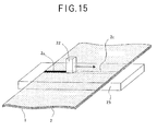
- FIG. 15 is a descriptive view illustrating the other embodiment of the present invention.
- a formed body made of thermoplastic resin having substantially the same width as a prescribed width of the peeled portion to be formed of the active material layer 2 for the purpose of continuous impregnation of the portion to be peeled of the active material layer 2
- the formed body 22 made of the thermoplastic resin having substantially the same size as the portion to be peeled of the active material layer 2.
- the active material layer 2 is heated, as in the embodiment shown in FIG. 14, to a prescribed temperature, and the active material layer 2 is continuously moved in a direction of an arrow shown in FIG. 15 to be impregnated with the thermoplastic resin , while pressing the formed body 22 made of the thermoplastic resin on the heated surface of the active material layer.
- the moving velocity in the above-mentioned step is determined so that the active material layer is impregnated with the thermoplastic resin in a sufficient amount thereof, taking into consideration a melting point or a softening point of the formed body 22 and a temperature of the active material layer 2.
- FIG. 16 shows an example of a step of peeling the active material layer 2 impregnated with the thermoplastic resin in accordance with the step as shown in FIG. 15.
- FIG. 16(a) shows the thermoplastic resin in a solidified condition after the impregnation step and the cooling step.
- cracks 24 tend to easily occur not only at the boundary between the impregnated portion 2a of the active material layer 2 and the non-impregnated portion thereof, but also in the impregnated portion itself, since the impregnated portion of the active material layer 2 has a large density to be hard and brittle, whereas there is no occurrence of cracks and the peeling in the non-impregnated portion of the active material layer 2, due to the binder contained in the non-impregnated portion thereof.
- the polypropylene wax is used, such a phenomenon occurs remarkably.
- the above-mentioned cracks may occur through the shrinkage of the impragnated portion of the active material layer 2, when cooling it.
- the adhesive strength between the collector 1 and the thermoplastic resin in the impregnated portion of the active material layer 2 is smaller than that in the non-impregnated portion thereof. It is therefore possible to easily peel the impregnated portion of the active material layer 2 by scraping softly the impregnated portion, or blowing air thereto in a state as shown in FIG. 16(b) or a state in which the electrode plate is restored from the bending condition.
- the non-coated portion (i.e., peeled portion) having a sharp edge can easily be formed on the collector 1 on the basis of the prescribed pattern in this manner.
- thermoplastic resin With respect to a method of impregnating the active material layer 2 with the thermoplastic resin, there may be used a method of impregnating the active material layer 2 with the thermoplastic resin by arranging a formed body made of thermoplastic resin and having a prescribed pattern on the active material layer 2 and heating the active material layer 2, or another method of pressing a formed body made of thermoplastic resin and having a prescribed pattern on the heated active material layer 2 at a prescribed pressure to melt the thermoplastic resin which is in contact with the active material layer 2 and to impregnate the active material layer 2 with the thermoplastic resin.
- the step of peeling the impregnated portion 2a of the active material layer 2 there may be used any one of a method of vibrating the electrode plate, a method of applying tension to the collector 1 to lift up the impregnated portion 2a, a method of peeling it with the use of an adhesive tape, to which the present process of the present invention is not however limited.
- thermoplastic resin for peeling the impregnated portion 2a of the active material layer 2 in the present invention
- material which is easily melted by heat i.e., thermoplastic resin generally used, as well as for example, low-molecular weight polyethylene, polypropylene, derivatives thereof, many kinds of wax, or the like.
- thermoplastic resin generally used, as well as for example, low-molecular weight polyethylene, polypropylene, derivatives thereof, many kinds of wax, or the like.
- Such materials preferably have a heat resistant property, and a poor adhesivity to the collector made of the metallic foil as well as a low extensibility for the precise formation of the non-coated portion on the basis of the prescribed pattern.
- the above-described thermoplastic resin preferably has a melting point of from 20°C to 250°C, and more preferably of form 60°C to 150°C.
- the melting point of the thermoplastic resin is excessively low, it softens at a room temperature, leading to hard handling thereof and a poor productivity of the electrode plate.
- the melting point thereof is excessively high, on the other hand, there occurs uneconomical problem in energy, and the collector as a substrate may be damaged when causing the impregnation of the active material layer with the thermoplastic resin.
- the thermoplastic resin preferably has viscosity of from 100 to 50,000 cP when the melting thereof, and more preferably of from 400 to 6,000 cP.
- thermoplastic resin When the viscosity of the thermoplastic resin is excessively high, there occurs uneconomical problem in energy. When the viscosity thereof is excessively low, the thermoplastic resin in a molten state tends to spread over in the inside of the active material coating layer 2 in a direction along a plane parallel to the surface thereof by the capillary phenomenon, thus making it impossible to form a sharp pattern.
- Polyethylene or polypropylene suitably used as the thermoplastic resin in the present invention may be exemplified by that of a non-oxidized low density type, a non-oxidized middle density type, a non-oxidized high density type, an oxidized low density type, an oxidized middle density type, an oxidized high density type, a non-polarity type, a polarity type, a fine powdery type or the like, and any one of them is applicable to the present invention.
- a formed body made of such a thermoplastic resin having an appropriate shape.
- the molten thermoplastic resin it is necessary for the molten thermoplastic resin to permeate through fine cavities in the coating layer 2 so as to reach the boundary between the collector land the active material layer. If the molten thermoplastic resin is solidified before it reaches the boundary therebetween, a portion to be removed of the coating layer 2 may be left non-peeled even when the resin-impregnated portion is peeled from the collector 1.
- the collector 1 may sufficiently be heated to delay the solidification of the thermoplastic resin, or the thermoplastic resin having low viscosity may be selected to increase the permeating velocity of thereof, or the thermoplastic resin may be kept at a sufficiently high temperature to delay the solidification thereof.
- thermoplastic resin in a molten state on the active material layer Accordingly, when there is applied a method of applying the thermoplastic resin in a molten state on the active material layer, according as a thickness of the active material layer is increased, there is required a long period of time of several ten seconds for the completion of permeation of the thermoplastic resin. There may be a case that complete permeation of the thermoplastic resin through the boundary between the active material layer and the collector cannot be achieved by one step, even when a lot of time is taken. Accordingly, when the active material layer has a large thickness, one permeation step may require a period of time of from several ten seconds to several minutes, or the same permeation step must be repeated, as an occasion demands.
- thermoplastic resin When there is used, in replacement of the step of applying the molten thermoplastic resin onto the active material layer, a step of pressing the formed body made of the thermoplastic resin to the active material layer, to cause only the portion of the thermoplastic resin, which is in contact with the active material layer, to be melted so as to permeate through the active material layer, it is possible to cause the thermoplastic resin to reach the surface of the collector for few seconds, thus permitting remarkable reduction in time required for forming the non-coating portion (i.e., the peeled portion) on the basis of the prescribed pattern.
- the secondary battery with a noaqueous electrolyte may be exemplified by a lithium secondary battery, and is characterized in the use of the nonaqueous organic solvent as an electrolyte.
- the coating layer i.e., the active material coating layer
- the nonaqueous organic solvent is used as an electrolyte.
- charge and discharge can be performed by interchange of electrons during the movement of a lithium ion between the positive electrode and the negative electrode.
- a metallic foil such as for example an aluminum foil, a copper foil or the like.
- Such a metallic foil preferably has a thickness of from about 10 ⁇ m to about 30 ⁇ m.
- either the active material layer for the positive electrode, or the active material layer for the negative electrode is formed on the collector 1.
- a coupling agent layer may be formed on the surface of the collector 1 in order to improve the adhesivity between the collector 1 and the active material layer for the positive or negative electrode.
- a coupling agent used for the formation of the coupling agent layer there may be used a coupling agent having an excellent adhesivity to both of the collector 1 made of a metallic foil and the active material layer, which is appropriately selected from the coupling agents such as a silane-coupling agent, a titanate-coupling agent, an aluminum-coupling agent and the like.
- an active material for the positive electrode used in the present invention there may be used at least one kind of lithium oxides such as LiCoO 2 , LiNiO 2 , LiMn 2 O 4 and the like, and chalcogen compounds such as TiS 2 , MnO 2 , MoO 3 , V 2 O 5 and the like.
- As an active material for the negative electrode on the other hand, it is preferable to use metallic lithium, lithium alloy and carbonacious material such as graphite, carbon black and acetylene, or material capable of intercalating lithium ions.
- LiCoO 2 is used as the active material for the positive electrode and the carbonacious material is used as the active material for the negative electrode, it is possible to obtain a lithium secondary battery having a high discharge voltage of about 4 volt.
- powder of the active material having a particle size of from 1 to 100 ⁇ m and an average particle size of about 10 ⁇ m.
- thermoplastic resin such as polyester resin, polyamide resin, polyacrylic acid-ester resin, polycarbonate resin, polyurethane resin, cellulose resin, polyolefin resin, polyvinyl resin, fluororesin, polyimide resin or the like
- thermosetting resin such as rubber type resin, acrylic resin, urethane resin or the like
- ionizing radiation-setting resin such as acrylate monomer, oligomer or the mixture thereof; or the mixture of these kinds of resin.
- the binder and the powdery active material which are appropriately selected from the above-described materials, are added to a dispersing medium comprising an organic solvent such as toluene, methyl ethyl ketone, N-methyl-2-pyrrolidone, the mixture thereof or the like, and a conductive agent is added to the dispersing medium, as an occasion demands, to prepare a mixture.
- a dispersing medium comprising an organic solvent such as toluene, methyl ethyl ketone, N-methyl-2-pyrrolidone, the mixture thereof or the like
- a conductive agent is added to the dispersing medium, as an occasion demands, to prepare a mixture.
- the thus prepared mixture is subjected to a mixing and dispersing process with the use of the conventional dispersing apparatus such as a homogenizer, a ball mill, a sand mill, a roll mill and the like.
- a total amount of the active material and the binder is preferably within a range of from about 40 to 80 wt. parts relative to 100 wt. parts of the whole coating composition, and the ratio of the active material to the binder is preferably within a range of from 9:1 to 8:2.
- a conductive agent added as an occasion demands in the preparation of the coating composition there may be used for example carbonacious material such as graphite, carbon black, acetylene black or the like.
- a method of applying the coating composition on the surface of the collector made of a metallic foil there may be used a conventional coating method such as a gravure coating method, a gravure reverse coating method, a roll coating method, a Mayer bar coating method, a blade coating method, a knife coating method, an air knife coating method, a slot die coating method, a slide die coating method, a dip coating method or the like.
- the drying step is carried out to remove the dispersing medium from the coating composition layer 2b formed as described above in the following manner, to prepare an active material layer.
- a heat source in the drying step there may be used hot air, infrared radiation, microwave, high-frequency wave, or the combination thereof.
- the coating composition layer may be dried by heat radiated from the metallic rollers, the metallic sheet, and the like which support the collector 1 in the drying step.
- the active material layer has a thickness of from 10 to 200 ⁇ m, preferably of from 50 to 150 ⁇ m.
- the coating amount of the coating composition is previously determined so that the resultant active material layer has a thickness within the above-mentioned range.
- the coating layer obtained by carrying out the above-mentioned applying and drying steps is preferably subjected to a press treatment with the use of a metallic roll, a heating roll, a sheet pressing machine or the like, to prepare the electrode plate of the present invention, in order to improve homogeneousness of the coating layer.
- the pressing condition of from 500kgf/cm 2 to 7,500kgf/cm 2 , more preferably of from 3,000kgf/cm 2 to 5,000kgf/cm 2 may be applied to the above-described press treatment. With a pressing force of under 500kgf/cm 2 , the homogeneousness of the coating layer may not sufficiently be improved.
- the electrode plate itself including the collector may be broken, thus causing an unfavorable problem.
- the lithium secondary battery is produced with the use of the thus prepared electrode plates, as positive and negative plates, of the present invention for a secondary battery with a nonaqueous electrolyte
- a nonaqueous electrolyte which is obtained by dissolving lithium salts as solute into an organic solvent.
- lithium salts as solute forming the nonaqueous electrolyte there may be used inorganic lithium salt such as LiClO 4 , LiBF 4 , LiPF 6 , LiAsF 6 , LiCl, LiBr or the like, or organic lithium salt such as LiB(C 6 H 5 ) 4 , LiN(SO 2 CF 3 ) 2 , LiC(SO 2 CF 3 ) 3 , LiOSO 2 CF 3 , LiOSO 2 C 2 F 5 , LiOSO 2 C 3 F 7 , LiOSO 2 C 4 F 9 , LiOSO 2 C 5 F 11 , LiOSO 2 C 6 F 13 , LiOSO 2 C 7 F 15 , or the like.
- inorganic lithium salt such as LiClO 4 , LiBF 4 , LiPF 6 , LiAsF 6 , LiCl, LiBr or the like
- organic lithium salt such as LiB(C 6 H 5 ) 4 , LiN(SO 2 CF 3 ) 2
- cyclic esters there may be used, as an organic solvent, cyclic esters, chain esters, cyclic ethers, chain ethers or the like.
- the cyclic esters may be exemplified by propylene carbonate, butylene carbonate, ⁇ -buthyrolactone, vinylene carbonate, 2-methyl- ⁇ -buthyrolactone, acetyl- ⁇ -buthyrolactone and ⁇ -valerolactone.
- the chain esters may be exemplified by dimethyl carbonate, diethyl carbonate, dibutyl carbonate, dipropyl carbonate, methyl ethyl carbonate, methyl butyl carbonate, methyl propyl carbonate, ethyl butyl carbonate, ethyl propyl carbonate, butyl propyl carbonate, propionic acid alkyl ester, malonic acid dialkyl ester and acetic acid alkyl ester.
- the cyclic ethers may be exemplified by tetrahydrofuran, alkyltetrahydrofuran, dialkyltetrahydrofuran, alkoxytetrahydrofuran, dialkoxytetrahydrofuran, 1,3-dioxolan, alkyl-1,3-dioxolan and 1,4-dioxolan.
- the chain ethers may be exemplified by 1,2-dimethoxyethane, 1,2-diethoxyethane, diethyl ether, ethylene glycol dialkylether, diethylene glycol dialkylether, triethylene glycol dialkylether and tetraethylene glycol dialkylether.
- the process of the present invention in the fourth group comprises a preparation step, an impregnation step, a solidification step and a peeling step.
- FIG. 17(a) illustrates the preparation step
- FIG. 17(b) illustrates the impregnation step
- FIG. 17(c) illustrates the solidification step
- FIG. 17(d) illustrates the peeling step.
- a porous coating layer 2 is formed on a collector 1 as a substrate by applying a coating composition for an electrode plate, which comprises active material and a binder onto the collector 1, and drying same, as shown in FIG. 17(a).
- a metallic foil such as for example an aluminum foil, a copper foil or the like.
- Such a metallic foil preferably has a thickness of from about 10 ⁇ m to about 30 ⁇ m.
- the active material may be classified into an active material for the positive electrode and an active material for the negative electrode.
- an active material for the positive electrode used in the present invention there may be used at least one kind of lithium oxides such as LiCoO 2 , LiNiO 2 , LiMn 2 O 4 and the like, and chalcogen compounds such as TiS 2 , MnO 2 , MoO 3 , V 2 O 5 and the like.
- the active material mentioned above may be used alone or in combination with the other active material.
- As an active material for the negative electrode it is preferable to use lithium-containing metal such as metallic lithium and lithium alloy, or carbonacious material such as graphite, carbon black, acetylene or the like.
- LiCoO 2 is used as the active material for the positive electrode and the carbonacious material is used as the active material for the negative electrode, it is possible to obtain a lithium secondary battery having a high discharge voltage of about 4 volt. It is preferable to disperse uniformly these active materials in the coating layer as formed. For this reason, it is preferable to use powder of the active material having a particle size of from 1 to 100 ⁇ m and an average particle size of about 10 ⁇ m.
- the binder for preparing the active material coating composition for the electrode plate is required to be chemically stable against the nonaqueous electrolyte, insoluble in the electrolyte, and soluble in a certain solvent to be able to be applied to the surface of the substrate in the form of thin film.
- a binder used in the process of the present invention there may be selectively used for example thermoplastic resin, i.e., polyester resin, polyamide resin, polyacrylic acid-ester resin, polycarbonate resin, polyurethane resin, cellulose resin, polyolefin resin, polyvinyl resin, fluororesin and polyimide resin.
- thermoplastic resin i.e., polyester resin, polyamide resin, polyacrylic acid-ester resin, polycarbonate resin, polyurethane resin, cellulose resin, polyolefin resin, polyvinyl resin, fluororesin and polyimide resin.
- compounds in which reactive functional group is introduced i.e., acrylate monomer or oligomer
- the binder and the powdery active material which are appropriately selected from the above-described materials, are added to a dispersing medium or a solvent comprising an organic solvent such as N-methyl-2-pyroridone and toluene, and a conductive agent is added to the dispersing medium, as an occasion demands, to prepare a mixture.
- the thus prepared mixture is subjected to a mixing and dispersing process with the use of the conventional dispersing apparatus such as a homogenizer, a ball mill, a sand mill, a roll mill and the like.
- the same mixing ratio of the binder and the active material as the conventional mixing ratio thereof.
- the mixing weight ratio of the binder : the active material 5:5 through 1:9 for the positive electrode plate
- the mixing weight ratio of the binder : the active material 2:8 through 1:9 for the negative electrode plate.
- a conductive agent added as an occasion demands there may be used for example carbonacious material such as graphite, carbon black, acetylene black or the like.
- the thus prepared coating composition for the electrode plate, containing the active material is applied on the collector as a substrate with the use of a gravure coater, a gravure reverse coater, a die coater, a slide coater or the like, and then dried to form the coating layer.
- the applying step and the drying step may be carried out several times to prepare a coating layer having the thickness of from 10 to 200 ⁇ m, preferably of from 50 to 170 ⁇ m.
- the coating layer obtained by carrying out the above-mentioned applying and drying steps is be subjected to a press treatment with the use of a metallic roll, a heating roll, a sheet pressing machine or the like, it is possible to improve homogeneousness of the coating layer.
- the above-described press treatment is not always essential.
- the pressing condition of from 500kgf/cm 2 to 7,500kgf/cm 2 , more preferably of from 3,000kgf/cm 2 to 5,000kgf/cm 2 may be applied to the above-described press treatment. With a pressing force of under 500kgf/cm 2 , the homogeneousness of the coating layer may not sufficiently be improved. With a pressing force of over 7,500kgf/cm 2 , the electrode plate itself including the collector may be broken, thus causing an unfavorable problem.
- the coating layer having a uniform thickness and excellent homogeneousness can be obtained by carrying out the above-described preparation step.
- the above-described coating layer 2 is impregnated with a solidifiable material 3 as a liquid material, which has a larger cohesion after solidification thereof than that of the coating layer 2, to form an impregnated-portion 2a of the coating layer having a prescribed pattern.
- the solidifiable material 3 is required to have a larger cohesion after solidification thereof than that of the coating layer 2. In other words, the solidifiable material 3 should solidify to become harder than the coating layer. When the solidifiable material 3 has a smaller cohesion after solidification than that of the coating layer, it is hard to perform a complete and precise peeling step of the solidifiable material-impregnated portion of the coating layer.
- the impregnated portion may be left non-peeled on the surface of the collector in the prescribed pattern, the non-peeled portion may have a blunt edge, leading to poor measurement accuracy of the pattern, and the adhesivity of the porous sheet to the coating layer may become low, thus making it impossible to peel the impregnated portion of the coating layer together with the porous sheet.
- the term “cohesion” means not only a cohesive force in the narrow sense, but also a general force which have an action of solidifying material or maintaining material in a solid state. Accordingly, the term “cohesion” in the present invention includes interatomic or intermolecular attractive forces as a cohesive force in the narrow sense, as well as forces which contribute to chemical bond such as, for example, intermolecular covalent bond.
- the solidifiable material which has any solidification machanism there may be used, for example, material such as polymerization material or cross-linking material, which irreversibly solidifies through a chemical reaction. It is however convenient to use material which permits irreversible repetition of solidification and liquefaction in accordance with certain conditions. Material which is solid at a room temperature, and can be liquefied by heat, is remarkably convenient in use in the actual working, since it is possible to adjust its flowability by heat.
- a heat-fusible material may suitably be used as material which is solid at a room temperature, and can be liquefied by heat.
- the heat-fusible material may exemplified by thermoplastic resin containing at least one kind of ethylene- or propylene-homopolymer or copolymer (for example, polyethylene, polypropylene, ethylene copolymer, propylene copolymer, or the like); organic or inorganic wax and the like.
- the heat-fusible material used as a solidifiable material preferably has a melting point within a range of from 20°C to 250°C, preferably within a range of from 60°C to 150°C.
- a melting point of the heat-fusible material is excessively low, it softens at a room temperature, leading to hard handling thereof and a poor productivity of the electrode plate.
- the melting point thereof is excessively high, on the other hand, there occurs uneconomical problem in energy.
- the heat-fusible material preferably has viscosity of from 10 to 50,000 cP when the melting thereof, and more preferably of from 400 to 6,000 cP.
- the viscosity of the heat-fusible material is excessively high, the heat-fusible material tends to not permeate easily into fine cavities of the active material coating layer 2, leading to a poor productivity of the electrode plate.
- the viscosity thereof is excessively low, the heat-fusible material tends to spread over in the inside of the active material coating layer 2 in a direction along a plane parallel to the surface thereof by the capillary phenomenon, thus making it impossible to form a sharp pattern.
- the coating layer 2 When the coating layer 2 is impregnated with the above-mentioned solidifiable material as a liquid material, it is necessary for the solidifiable material to permeate through fine cavities in the coating layer 2 so as to reach the surface of the collector 1. If the solidifiable material is solidified before it reaches the surface of the collector 1, a portion to be removed of the coating layer 2 may be left non-peeled even when the coating layer 2 impregnated with the solidifiable material is peeled from the collector 1.
- At least one of the collector 1 and the coating layer 2 may be heated to an appropriate temperature to delay the solidification of the solidifiable material, or the solidifiable material having a low viscosity may be selected to increase the permeating velocity of thereof, or the solidifiable material may be kept at a sufficiently high temperature to delay the solidification thereof.
- the liquefied solidifiable material 3 is applied onto the prescribed portion of the coating layer 2 by means of a conventional coating apparatus such as a dispenser, a gravure roll, a die head and the like.
- a conventional coating apparatus such as a dispenser, a gravure roll, a die head and the like.
- the heat-fusible material is used as a solidifiable material
- the impregnated portion having the prescribed pattern having an excellent measurement accuracy can be obtained by carrying out the above-described impregnation step.
- a porous sheet 25 is brought into contact with the portion 2a of the coating layer, which is impregnated with the solidifiable material on the basis of the prescribed pattern, to cause part of the solidifiable material in the inside or on the surface of the impregnated portion 2a to migrate into the porous sheet 25.
- the migration of the solidifiable material causes the formation of an impregnated portion 25a also in the portion of the porous sheet 25, which corresponds to the impregnated portion 2a. Then, the solidifiable material in the impregnated portion 2a and the solidifiable material in the porous sheet 25 solidifies in an integral form.
- the portion of the coating layer 2 impregnated with the solidifiable material is normally stuck to the collector 1 in a smaller strength, and this portion can easily be peeled.
- tension may be imparted to the collector 1 to lift up the portion of the coating layer 2 impregnated with the solidiable material from the collector 1 so as to perform the peeling thereof, or it may be peeled from the collector 1 by means of a spatula, or it may be peeled with the use of an adhesive tape, or it may be peeled from the collector 1 by the blowing of air.
- the entire impregnated portions 2a can be peeled only by one operation with the use of the porous sheet in the present invention, the working efficiency can remarkably be improved. Moreover, the process of the present invention causes no production of small flakes of the peeled portion, unlike the method in which the spatula or the air gun is used.
- the method of peeling the portion of the coating layer utilizing the solidifiable material use of a certain kind of the solidifiable material may cause the occurrence of cracks in the coating layer which is obtained by impregnating the portion of the coating layer with the solidifiable material and solidifying same.
- the solidifiable material having a larger cohesion makes it easy to peel the portion of coating layer, whereas it tends to easily cause the occurrence of cracks on the coating layer.
- Such occurrence of cracks leads to some adverse effects.
- the first adverse effect is of a problem that the peeling of the coating layer with cracks may cause the production of marks of the cracks on the exposed surface of the substrate.
- the marks of the cracks is produced by leaving a small amount of coating layer non-peeled in a form of stripe along the portion having the cracks, thus meaning insufficient peeling of the impregnated portion of the coating layer on the basis of the pattern. It is possible to completely inhibit the formation of the coating layer having the cracks by repeating the applying step of the solidifiable material and the peeling step at least twice, however such a method leads to excessive degradation of productivity, and poor measurement accuracy of the pattern.
- the second adverse effect is of a problem that the occurrence of the cracks in the vicinity of the edge portion of the pattern easily tends to leave flakes of the coating layer non-peeled, which is obtained by impregnating the portion of the coating layer with the solidifiable material and solidifying same, on the edge portion of the pattern.
- Such a phenomenon means that the non-peeled portion has a blunt edge, leading to poor measurement accuracy of the pattern.
- porous sheet 25 there may be used any one of polyester mesh, metallic mesh, cloth, paper and a nonwoven fabric cloth.
- the thickness of the porous sheet 25 is preferably be as smaller as possible, provided that the porous sheet 25 has a sufficient strength so that the porous sheet 25 can peeled together with the impregnated portion 2a without causing any problems in the subsequent peeling step.
- the thickness thereof is preferably up to 400 ⁇ m, more preferably within a range of from 40 to 120 ⁇ m. With a thickness of over 400 ⁇ m, the greater part of the molten solidifiable material existing in the impregnated portion 2a may migrate into the porous sheet 25 by the capillary phenomenon, leading to insufficient peeling of the impregnated portion 2a.
- a diameter of fibers of the porous sheet 25 and a porosity thereof may have an effect on the formation of the pattern.
- the diameter of the fibers of the porous sheet 25 is preferably up to 150 ⁇ m, more preferably within a range of from 30 to 70 ⁇ m. With a diameter of fibers of the porous sheet 25 of larger than 150 ⁇ m, the adhesive strength (namely, the sticking strength) between the porous sheet 25 and the solidifiable material becomes low.
- the porosity of the porous sheet 25 is preferably kept as high as possible. In case of a mesh sheet such as a polyester mesh, a metallic mesh or the like, the porosity thereof is preferably kept at least 30%, more preferably within a range of from 50 to 80%.
- porosity is a value expressed in a ratio of the total area of gap portions excluding the area occupied by the fibers to the area of the entire porous sheet 25, in a plane view thereof.
- the porosity of the mesh sheet may vary depending on the diameter of the fibers and the weaving method.
- the impregnated portion 2a and the porous sheet 25 can integrally be bonded by permeating the molten solidifiable material into the cavities of the impregnated portion 2a, bringing, prior to the solidification of the solidifiable material, the porous sheet 25 into contact with the surface of the impregnated portion 2a of the coating layer to cause part of the solidifiable material to permeate into the porous sheet 25, and cooling and solidify same.
- the impregnated portion 2a and the porous sheet 25 can integrally be bonded by permeating the molten solidifiable material into the cavities of the impregnated portion 2a, cooling and solidifying same, bringing the porous sheet 25 into contact with the surface of the impregnated portion 2a of the coating layer, heating the contact portion thereof to remelt the solidifiable material to cause part of the solidifiable material to permeate into the porous sheet 25, and cooling and solidify same again.
- any kind of conventional means such as a heat roll, a heating plate, a dryer, an infrared radiation, and the like.
- heat radiation is performed from the metallic mesh itself through high-frequency induction heating.
- a heating element such as nichrome wire may be used as a composing material of the porous sheet 25.
- the impregnated portion 2a and the porous sheet 25 can integrally be bonded by permeating the molten solidifiable material into the cavities of the impregnated portion 2a, cooling and solidifying same, bringing the heated porous sheet 25 into contact with the surface of the impregnated portion 2a of the coating layer, to remelt the solidifiable material in the contact portion thereof to cause part of the solidifiable material to permeate into the porous sheet 25, and cooling and solidify same again.
- the porous sheet may previously be heated by any kind of conventional means such as a heat roll, a heating plate, a dryer, an infrared radiation, and the like.
- heat radiation may be previously performed from the metallic mesh itself through high-frequency induction heating.
- a heating element such as nichrome wire may be used as a composing material of the porous sheet 25, and the previous heating with the use of this heating element may be performed.
- the impregnated portion 2a and the porous sheet 25 can integrally be bonded by any one of the above-described methods, it is possible to remove the entire impregnated portions by only one operation in the subsequent peeling step.
- portion 2a impregnated with the solidifiable material is peeled together with the porous sheet 25 sticking thereon in the integral solidification state of the solidifiable material in the coating layer 2 and the solidifiable material in the porous sheet 25, to expose the surface of the collector 1 on the basis of the prescribed pattern to obtain the peeled portion 4.
- the peeling step is carried out in a state of application of tension to the porous sheet 25, it is preferable to carry out the peeling step by keeping the original sheet 27 for the electrode plate away from the porous sheet 25 with a peeling roll 26 as a diverging point as shown in FIG. 19.
- the peeling roll 26 is not required since the peeling step can be carried out without causing the loosening of the porous sheet 25 in the analogous condition to the above-mentioned case in which tension is applied to the porous sheet 25.
- the porous sheet 25 may have a shape of postal card, or a strip-shape.
- FIG. 20 illustrates an exemplified use of the strip-shaped porous sheet 25.
- the porous sheet 25 is supplied from a feeding roll 28 while applying tension to the porous sheet 25, and the porous sheet 25 is supported by support rolls 30, 30 and then wound by a winding roll 29.
- the original strip-shaped sheet 27 for the electrode plate is supplied, on the other hand, by a feeding roll 32, supported by support rolls 26, 26, and then wound by a winding roll 33.
- the original sheet 27 for the electrode plate is continuously impregnated with the molten solidifiable material on the prescribed pattern by means of a coating apparatus 10.
- the porous sheet 25 is placed on the original sheet 27 for the electrode plate, and then, the solidifiable material is cooled and solidified by means of a cooling and solidifying apparatus 31. Then, the porous sheet 25 is peeled from the original sheet 27 for the electrode plate, while keeping the original sheet 27 for the electrode plate away from the porous sheet 25 with a peeling roll 26 as a diverging point. Finally, a strip-shaped sheet having a plurality of electrode plates in each of which the surface of the collector is partially exposed on the basis of the prescribed pattern, is continuously wound by means of a winding roll 33. According to the process of the present invention as shown in FIG. 20, it is possible to continuously produce the strip-shaped sheet having a plurality of electrode plates.
- FIG. 21 illustrates the step of peeling the original sheet 27 for the electrode plate from the porous sheet 25 by moving horizontally the peeling roll 26 in a direction of an arrow as shown in FIG. 21, while applying tension to the porous sheet 25.
- the porous sheet 25 may be used once and then thrown away, or may be reusable after washing or cleaning it.
- the electrode plate for a secondary battery with a nonaqueous electrolyte having the non-coated portion on the basis of the prescribed pattern by carrying out the above-described steps (a) to (d) in this order.
- the non-coated portion of the thus produced electrode plate is excellent in measurement accuracy of the pattern, and in the non-coated portion therof, there is no production of powdery flakes from the edge portion of the pattern, and no existence of marks of cracks.
- the secondary battery is produced with the use of the electrode plate of the present invention, which has been prepared in the above-described manner, it is preferable to apply a heating treatment and a decompression treatment to the electrode plate prior to the assembling step of the secondary battery, in order to remove moisture in the coating layer of the electrode plate, which contains the active material.
- the lithium secondary battery for example, the lithium secondary battery is produced with the use of the above-described electrode plate, there is used a nonaqueous electrolyte which is obtained by dissolving lithium salts as solute into an organic solvent.
- a nonaqueous electrolyte which is obtained by dissolving lithium salts as solute into an organic solvent.
- the cyclic esters may be exemplified by propylene carbonate, butylene carbonate, ⁇ -buthyrolactone, vinylene carbonate, 2-methyl- ⁇ -buthyrolactone, acetyl- ⁇ -buthyrolactone and ⁇ -valerolactone.
- the chain esters may be exemplified by dimethyl carbonate, diethyl carbonate, dibutyl carbonate, dipropyl carbonate, methyl ethyl carbonate, methyl butyl carbonate, methyl propyl carbonate, ethyl butyl carbonate, ethyl propyl carbonate, butyl propyl carbonate, propionic acid alkyl ester, malonic acid dialkyl ester and acetic acid alkyl ester.
- the cyclic ethers may be exemplified by tetrahydrofuran, alkyltetrahydrofuran, dialkyldialkyltetrahydrofuran, alkoxytetrahydrofuran, dialkoxytetrahydrofuran, 1,3-dioxolan, alkyl-1,3-dioxolan and 1,4-dioxolan.
- the chain ethers may be exemplified by 1,2-dimethoxyethane, 1,2-diethoxyethane, diethyl ether, ethylene glycol dialkylether, diethylene glycol dialkylether, triethylene glycol dialkylether and tetraethylene glycol dialkylether.
- lithium salts as solute forming the nonaqueous electrolyte in cooperation with the above-mentioned organic solvent, there may be used inorganic lithium salt such as LiClO 4 , LiBF 4 , LiPF 6 , LiAsF 6 , LiCl, LiBr or the like, or organic lithium salt such as LiB(C 6 H 5 ) 4 , LiN(SO 2 CF 3 ) 2 , LiC(SO 2 CF 3 ) 3 , LiOSO 2 CF 3 , LiOSO 2 C 2 F 5 , LiOSO 2 C 3 F 7 , LiOSO 2 C 4 F 9 , LiOSO 2 C 5 F 11 , LiOSO 2 C 6 F 13 , LiOSO 2 C 7 F 15 , or the like.
- inorganic lithium salt such as LiClO 4 , LiBF 4 , LiPF 6 , LiAsF 6 , LiCl, LiBr or the like
- organic lithium salt such as LiB(C 6 H 5 ) 4
- a coating composition for a positive electrode, containing active material for the positive electrode was prepared in the following manner.
- Materials for the coating composition for the positive electrode composed of LiCoO 2 powder of 40 wt. parts having a particle size of from 1 to 100 ⁇ m and an average particle size of 10 ⁇ m, graphite powder of 5.0 wt. parts as a conductive agent, polyvinylidene fluoride of 4 wt. parts as a binder (having the product name of "NEOFLON VDF, VP-850" manufactured by DAIKIN INDUSTRIES, CO. LTD.) and polyvinylidene fluoride of 20 wt. parts.
- polyvinylidene fluoride was previously dissolved by polyvinylidene fluoride to prepare varnish.
- the other powdery materials were added to the thus prepared varnish, and these powdery materials and the varnish were stirred and mixed by means of a planetary mixer (manufactured by KODAIRA SEISAKUSHO CO. LTD.) for a period of time of 30 minutes, to prepare a coating composition in a form of slurry for the positive electrode containing the active material for the positive electrode.
- the first coating step was carried out on a collector made of an aluminum foil having a thickness of 20 ⁇ m and a width of 300mm by means of a die coater. Then, a drying step was carried out at a temperature of 140°C for 2 minutes to form a coating layer on the aluminum foil, which included the active material for the positive electrode and had a thickness of 100 ⁇ m in a drying state.
- the resultant coating layer including the active material for the positive electrode was subjected to an aging treatment in a vacuum oven at a temperature of 80°C for 48 hours to remove moisture in the coating layer, thereby preparing an electrode plate for the positive electrode.
- a coating composition for a negative electrode, containing active material for the negative electrode was prepared in the following manner.
- Materials for the coating composition for the negative electrode composed of graphite powder of 85 wt. parts, polyvinylidene fluoride of 15 wt. parts (having the product name of "NEOFLON VDF, VP-850" manufactured by DAIKIN INDUSTRIES, CO. LTD.) and polyvinylidene fluoride as a dispersing medium of 225 wt. parts.
- a coating composition in a form of slurry for the negative electrode was obtained with the use of these materials by means of the same dispersing machine in the same dispersing method as in the case of preparation of the coating composition for the positive electrode.
- the first coating step was carried out on a collector made of a rolled copper foil having a thickness of 15 ⁇ m by means of a die coater. Then a drying step was carried out at a temperature of 140°C for 2 minutes to form a coating layer on the copper foil, which included the active material for the negative electrode and had a thickness of 100 ⁇ m in a drying state.
- the resultant coating layer including the active material for the negative electrode was subjected to the same aging treatment to remove moisture in the coating layer, thereby preparing an electrode plate for the negative electrode.
- the thus obtained electrode plates for the positive and negative electrodes were placed on a hot plate heated to a temperature of 90°C.
- Polypropylene (having the product name of "VISCOL 550P" manufactured by SANYO KASEI KOGYO CO. LTD.) which has been heated to a temperature of 250°C to melt it, was applied on these electrode plates in a shape of strip having a width of 10 mm and a length of 200 mm by means of a dispenser.
- the hot plate was removed, to solidify the polypropylene.
- the solidified polypropylene was easily peeled from the collector by applying tension to the collector to lift up the polypropylene, since it was hard and brittle.
- the collector had a non-coated portion on the basis of the prescribed pattern, which had a sharp edge and in which there was no production of powdery flakes of the coating layer.
- Electrode plates for the positive and negative electrodes were prepared under the same applying and drying conditions as in the Experiment Example No. 1-1.
- the thus obtained electrode plates for the positive and negative electrodes were placed on a hot plate heated to a temperature of 90°C.
- Polyethylene having the product name of "SANWAX 161P” manufactured by SANYO KASEI KOGYO CO. LTD.
- SANYO KASEI KOGYO CO. LTD. which has been heated to a temperature of 250°C to melt it, was applied on these electrode plates in a shape of strip having a width of 10 mm and a length of 200 mm by means of a dispenser.
- the hot plate was removed, to solidify the polyethylene.
- the solidified polyethylene was easily peeled, keeping its shape as applied, from the collector by pulling up the end of the solidified polyethylene, since it had a sufficient strength.
- the collector had a non-coated portion on the basis of the prescribed pattern, which had a sharp edge and in which there was no production of powdery flakes of the coating layer.
- Electrode plates for the positive and negative electrodes were prepared under the same applying and drying conditions as in the Experiment Example No. 1-1.
- the thus obtained electrode plates for the positive and negative electrodes were heated to a temperature of 70°C by means of an infrared lamp.
- Wax (having the product name of "DIACARNA 30L” manufactured by MITSUBISHI KASEI KOGYO CO. LTD.) which has been heated to a temperature of 160°C to melt it, was applied on these electrode plates in a shape of strip having a width of 10 mm and a length of 200 mm by means of a dispenser. Then, the infrared lamp was removed, to solidify the wax.
- the solidified wax was easily peeled from the collector by applying tension to the collector to lift up the wax, since it was hard and brittle.
- the collector had a non-coated portion on the basis of the prescribed pattern, which had a sharp edge and in which there was no production of powdery flakes of the coating layer.
- Electrode plates for the positive and negative electrodes were prepared under the same applying and drying conditions as in the Experiment Example No. 1-1. Then, a ribbon-shaped formed body having a width of 30 mm, a length of 200 mm and a thickness of 5 mm, and made of polyethylene (having the product name of "SANWAX 161P" manufactured by SANYO KASEI KOGYO CO. LTD.) was placed on the surface of the coating layer of each of these electrode plates. A hot plate heated to a temperature of 250°C was brought into contact with the back surface of the electrode plate for about one second, and then, the hot plate was removed therefrom. In this stage, part of polyethylene coming into contact with the coating layer was melted and permeated through the coating layer, and then solidified.
- polyethylene having the product name of "SANWAX 161P” manufactured by SANYO KASEI KOGYO CO. LTD.
- the solidified polyethylene was easily peeled, keeping its shape as applied, from the collector by pulling up the end of the solidified polyethylene.
- the collector had a non-coated portion on the basis of the prescribed pattern, which had a sharp edge and in which there was no production of powdery flakes of the coating layer.
- Electrode plates for the positive and negative electrodes were prepared under the same applying and drying conditions as in the Experiment Example No. 1-1.
- the thus obtained electrode plates for the positive and negative electrodes were subjected to a pressing treatment at a pressure of 3,000kgf/cm 2 by means of a roll press.
- These electrode plates having been subjected to the pressing treatment were placed on a hot plate heated to a temperature of 90°C.
- Polypropylene (having the product name of "VISCOL 550P" manufactured by SANYO KASEI KOGYO CO. LTD.) which has been heated to a temperature of 250°C to melt it, was applied on these electrode plates in a shape of strip having a width of 10 mm and a length of 200 mm by means of a dispenser.
- the hot plate was removed, to solidify the polypropylene.
- the solidified polypropylene was easily peeled from the collector by applying tension to the collector to lift up the polypropylene, since it was hard and brittle.
- the collector had a non-coated portion on the basis of the prescribed pattern, which had a sharp edge and in which there was no production of powdery flakes of the coating layer.
- Paste comprising frit of lead glass of 80 wt.%, ethylcellulose of 1 wt.%, buthylcarbinol acetate of 10 wt.% and a-terpineol of 9 wt.% and having viscosity of 80,000 cP was applied on the entire surface of a square glass plate as a substrate for a plasma-display panel, and then dried to prepare a coating layer.
- a square plastic sheet each side of which was smaller by 1 mm than the side of the square glass plate, was placed on the thus prepared coating layer so that the peripheral portion of the coating layer was exposed in a width of 0.5 mm.
- Polypropylene wax (having the product name of "VISCOL 550P” manufactured by SANYO KASEI KOGYO CO. LTD.) which has been heated to a temperature of 250°C to melt it, was applied on the thus exposed peripheral portion of the coating layer to impregnate this portion with polyethylene wax. After completion of the cooling of the impregnated portion of the coating layer, the impregnated portion was peeled from the glass plate, with the result that the peripheral portion having a width of 0.5 mm of the glass plate was clearly exposed. Then, the glass plate having the coating layer was sintered by a conventional method to form a primer layer.
- Electrode plates for the positive and negative electrodes were prepared under the same applying and drying conditions as in the Experiment Example No. 1-1.
- An adhesive tape having a width of 10 mm and a length of 200 mm was stuck onto each of the thus obtained electrode plates for the positive and negative electrodes, and then, the adhesive tape was peeled from each of the electrode plates to prepare a non-coated portion thereon.
- Much of portions to be removed of the coating layer were left non-peeled on the collector, and the non-coated portion had a blunt edge and in which there was observed the production of powdery flakes of the coating layer. It was also confirmed that such a peeling step with the use of the adhesive tape was not industrially applicable to an actual production.
- Electrode plates for the positive and negative electrodes were prepared under the same applying and drying conditions as in the Experiment Example No. 1-1.
- the coating layer of each of the electrode plates for the positive and negative electrodes was scraped off by means of a spatula to prepare a non-coated portion having a width of 10 mm and a length of 200 mm.
- Much of portions to be removed of the coating layer were left non-peeled on the collector, and it was hard to form the non-coated portion on the basis of the prescribed pattern. Scratches were observed on the surface of the collector.
- Electrode plates for the positive and negative electrodes were prepared under the same applying and drying conditions as in the Experiment Example No. 1-1.
- the thus obtained electrode plates for the positive and negative electrodes were kept at a room temperature.
- polypropylene having the product name of "VISCOL 550P” manufactured by SANYO KASEI KOGYO CO. LTD.
- SANYO KASEI KOGYO CO. LTD. which has been heated to a temperature of 250°C to melt it, was applied on these electrode plates in a shape of strip having a width of 10 mm and a length of 200 mm by means of a dispenser.
- the polypropylene was completely solidified by an air cooling step.
- the applied polypropylene was solidified on the surface of the coating layer prior to the permeation thereof through the inside the coating layer.
- the portion to be removed of the coating layer was left non-peeled on the surface of the collector, thus making it impossible to form any non-coated portion.
- Electrode plates for the positive and negative electrodes were prepared under the same applying and drying conditions as in the Experiment Example No. 1-1.
- the thus obtained electrode plates for the positive and negative electrodes were placed on a hot plate heated to a temperature of 70°C.
- Wax (having the product name of "SP-0145" manufactured by NIPPON SEIRO CO. LTD.) which has been heated to a temperature of 160°C to melt it, was applied on these electrode plates in a shape of strip having a width of 10 mm and a length of 200 mm by means of a dispenser.
- the hot plate was removed, to solidify the wax. Since the wax has a low viscosity when the melting thereof, it spread over in the inside of the coating layer in a direction along a plane parallel to the surface thereof by the capillary phenomenon, thus making it impossible to form a sharp pattern.
- a coating composition for a positive electrode, containing active material for the positive electrode was prepared in the following manner.
- Materials for the coating composition for the positive electrode composed of LiCoO 2 powder of 90 wt. parts having a particle size of from 1 to 100 ⁇ m and an average particle size of 10 ⁇ m, graphite powder of 5.0 wt. parts as a conductive agent, polyvinylidene fluoride of 4 wt. parts as a binder (having the product name of "NEOFLON VDF, VP-850" manufactured by DAIKIN INDUSTRIES, CO. LTD.) and N-methylpyrrolidone of 20 wt. parts.
- polyvinylidene fluoride was previously dissolved by polyvinylidene fluoride to prepare varnish.
- the other powdery materials were added to the thus prepared varnish, and these powdery materials and the varnish were stirred and mixed by means of a planetary mixer (manufactured by KODAIRA SEISAKUSHO CO. LTD.) for a period of time of 30 minutes, to prepare a coating composition in a form of slurry for the positive electrode containing the active material for the positive electrode.
- the thus prepared coating composition had viscosity of 39,000 cP.
- the coating composition for the positive electrode containing the active material for the positive electrode was applied on an area having a width of 300 mm and a length of 500 mm of a collector made of an aluminum foil having a thickness of 20 ⁇ m, a width of 320 mm and a length of 600 mm with the use of a coating apparatus under applying conditions comprising an inside diameter of a nozzle of 0.92 mm and a pressure of 0.2 kgf/cm 2 .
- the moving velocity of the nozzle was 30 mm/sec., and the forwarding pitch was G mm/min. during the applying step.
- the tip of the nozzle had a wide slit-shape, unlike the conventional needle-shape, thus permitting the application of the coating composition in a width of 30 mm by one operation.
- the applied coating composition was dried at a temperature of 80°C to remove the solvent contained therein, thereby forming an active material coating layer.
- a polyethylene terephthalate film was placed and pressed on the coating layer, and then this film was peeled therefrom.
- the coating layer was dried in an oven heated to a temperature of 120°C for two minutes.
- the coating layer had a thickness of 130 ⁇ m after the completion of the drying step.
- a non-woven fabric cloth having the product name of "FC-406” manufactured by JAPAN VILENE CO. LTD.
- polypropylene having the product name of "VISCOL 550P” manufactured by SANYO KASEI KOGYO CO. LTD.
- the thus prepared peeling sheet had a thickness of 470 ⁇ m, and an amount of polypropylene with which the non-woven fabric cloth was impregnated, was 270 g/cm 2 .
- the peeling sheet was placed on the active material coating layer, and they were pressed to each other by means of a flat plate press having a width of 305 mm and a length of 25 mm.
- the pressing conditions comprised a pressure of 50kgf/cm 2 and a pressing time of three seconds.
- the flat plate press comprised two flat pressing plates, one plate coming into contact with the surface of the electrode plate, which was opposite to the surface on which the active material layer has been formed, was kept at a temperature of 150°C, and the other plate was kept at a temperature of 25°C, which was equal to a room temperature.
- the distance between the two pressing plates was kept 125 ⁇ m during the pressing step.
- the collector After completion of the heat pressing step, they were left for one minute as they are, and then, the peeling sheet was peeled from the collector having the active material layer. In this stage, a portion of the active material layer was transferred to the peeling sheet, thereby permitting the easy peeling of the portion thereof on the basis of the prescribed pattern. As a result, the collector had a non-coated portion on the basis of the prescribed pattern, which had a sharp edge and in which there was no production of powdery flakes of the coating layer.
- a coating composition for a negative electrode, containing active material for the negative electrode was prepared in the following manner.
- Materials for the coating composition for the negative electrode composed of graphite powder of 85 wt. parts, polyvinylidene fluoride of 15 wt. parts as a binder (having the product name of "NEOFLON VDF, VP-850" manufactured by DAIKIN INDUSTRIES, CO. LTD.) and N-methylpyrrolidone of 225 wt. parts. These powdery materials were dispersed in a dispersing machine at 8,000 rpm, to prepare a coating composition for the negative electrode containing the active material for the negative electrode.
- the thus prepared coating composition had viscosity of 32,500 cP.
- the active material coating layer had a thickness of 100 ⁇ m after the completion of the drying step.
- a peeling sheet was prepared in the same manner as in the Experiment Example No. 2-1.
- the peeling sheet was placed on the active material coating layer, and they were pressed to each other by means of a flat plate press having a width of 305 mm and a length of 88 mm.
- the pressing conditions comprised a pressure of 125kgf/cm 2 and a pressing time of three seconds.
- the flat plate press comprised two flat pressing plates, one plate coming into contact with the surface of the electrode plate, which was opposite to the surface on which the active material layer has been formed, was kept at a temperature of 140°C, and the other plate was kept at a temperature of 25°C, which was equal to a room temperature.
- the distance between the two pressing plates was kept 125 ⁇ m during the pressing step.
- the collector After completion of the heat pressing step, they were left for one minute as they are, and then, the peeling sheet was peeled from the collector having the active material layer. In this stage, a portion of the active material layer was transferred to the peeling sheet, thereby permitting the easy peeling of the portion thereof on the basis of the prescribed pattern. As a result, the collector had a non-coated portion on the basis of the prescribed pattern, which had a sharp edge and in which there was no production of powdery flakes of the coating layer.
- a collector having an active material coating layer for the positive electrode and a peeling sheet were prepared in the same manner as in the Experiment Example No. 2-1.
- the peeling sheet was placed on the active material coating layer, and they were pressed to each other by means of a roll press having a width of 305 mm and a roll diameter of 200 mm.
- the pressing conditions comprised a linear pressure of 67kgf/cm and a traveling velocity of 12.6 cm/min.
- the roll press comprised two pressing rolls, one roll coming into contact with the surface of the electrode plate, which was opposite to the surface on which the active material layer has been formed, was kept at a temperature of 175°C, and the other roll was kept at a temperature of 25°C, which was equal to a room temperature.
- the distance between the two pressing rolls was kept 150 ⁇ m during the pressing step. After completion of the heat pressing step, they were left for one minute as they are, and then, the peeling sheet was peeled from the collector having the active material layer. In this stage, a portion of the active material layer was transferred to the peeling sheet, thereby permitting the easy peeling of the portion thereof on the basis of the prescribed pattern. As a result, the collector had a non-coated portion on the basis of the prescribed pattern, which had a sharp edge and in which there was no production of powdery flakes of the coating layer.
- a collector having an active material coating layer for the negative electrode and a peeling sheet were prepared in the same manner as in the Experiment Example No. 2-2.
- the peeling sheet was placed on the active material coating layer, and they were pressed to each other by means of a roll press having a width of 305 mm and a roll diameter of 200 mm.
- the pressing conditions comprised a linear pressure of 100kgf/cm and a traveling velocity of 12.6 cm/min.
- the roll press comprised two pressing rolls, one roll coming into contact with the surface of the electrode plate, which was opposite to the surface on which the active material layer has been formed, was kept at a temperature of 165°C, and the other roll was kept at a temperature of 25°C, which was equal to a room temperature.
- the distance between the two pressing rolls was kept 150 ⁇ m during the pressing step. After completion of the heat pressing step, they were left for one minute as they are, and then, the peeling sheet was peeled from the collector having the active material layer. In this stage, a portion of the active material layer was transferred to the peeling sheet, thereby permitting the easy peeling of the portion thereof on the basis of the prescribed pattern. As a result, the collector had a non-coated portion on the basis of the prescribed pattern, which had a sharp edge and in which there was no production of powdery flakes of the coating layer.
- a collector having an active material coating layer for the positive electrode, another collector having an active material coating layer for the negative electrode, and a peeling sheet were prepared in the same manner as in the Experiment Example Nos. 2-1 through 2-4, and the same heat pressing step and the same peeling step through the transfer action as therein were carried out, except that polyethylene (having the product name of "SANWAX 161P" manufactured by SANYO KASEI KOGYO CO. LTD.) was used as thermoplastic resin.
- the collector had a non-coated portion on the basis of the prescribed pattern, which had a sharp edge and in which there was no production of powdery flakes of the coating layer.
- a collector having an active material coating layer for the positive electrode, another collector having an active material coating layer for the negative electrode, and a peeling sheet were prepared in the same manner as in the Experiment Example Nos. 2-1 through 2-4, and the same heat pressing step and the same peeling step through the transfer action as therein were carried out, except that polyethylene (having the product name of "A-C392" manufactured by ALLIED SIGNAL CO. LTD.) was used as thermoplastic resin.
- the collector had a non-coated portion on the basis of the prescribed pattern, which had a sharp edge and in which there was no production of powdery flakes of the coating layer.
- a collector having an active material coating layer for the positive electrode, another collector having an active material coating layer for the negative electrode, and a peeling sheet were prepared in the same manner as in the Experiment Example Nos. 2-1 through 2-4, and the same heat pressing step and the same peeling step through the transfer action as therein were carried out, except that polyethylene (having the product name of "Hoechst-Wax PE190" manufactured by HOECHST INDUCTRY CO. LTD.) was used as thermoplastic resin.
- the collector had a non-coated portion on the basis of the prescribed pattern, which had a sharp edge and in which there was no production of powdery flakes of the coating layer.
- a collector having an active material coating layer for the positive electrode, another collector having an active material coating layer for the negative electrode, and a peeling sheet were prepared in the same manner as in the Experiment Example Nos. 2-1 through 2-4, and the same heat pressing step and the same peeling step through the transfer action as therein were carried out, except that polyethylene (having the product name of "Hoechst-Wax PE191" manufactured by HOECHST INDUCTRY CO. LTD.) was used as thermoplastic resin.
- the collector had a non-coated portion on the basis of the prescribed pattern, which had a sharp edge and in which there was no production of powdery flakes of the coating layer.
- a collector having an active material coating layer for the positive electrode, another collector having an active material coating layer for the negative electrode, and a peeling sheet were prepared in the same manner as in the Experiment Example Nos. 2-1 through 2-4, and the same heat pressing step and the same peeling step through the transfer action as therein were carried out, except that polyethylene (having the product name of "Luwax OA3 Powder” manufactured by BASF JAPAN CO. LTD.) was used as thermoplastic resin.
- the collector had a non-coated portion on the basis of the prescribed pattern, which had a sharp edge and in which there was no production of powdery flakes of the coating layer.
- a collector having an active material coating layer for the positive electrode, another collector having an active material coating layer for the negative electrode, and a peeling sheet were prepared in the same manner as in the Experiment Example Nos. 2-1 through 2-4, and the same heat pressing step and the same peeling step through the transfer action as therein were carried out, except that a non-woven fabric cloth (having the product name of "JH-1007" manufactured by JAPAN VILENE CO. LTD.) was used.
- the thus prepared peeling sheet had a thickness of 210 ⁇ m, and an amount of polypropylene with which the non-woven fabric cloth was impregnated, was 130 g/cm 2 .
- the collector had a non-coated portion on the basis of the prescribed pattern, which had a sharp edge and in which there was no production of powdery flakes of the coating layer.
- a collector having an active material coating layer for the positive electrode, another collector having an active material coating layer for the negative electrode, and a peeling sheet were prepared in the same manner as in the Experiment Example Nos. 2-1 through 2-4, and the same heat pressing step and the same peeling step through the transfer action as therein were carried out, except that a non-woven fabric cloth (having the product name of "WP-8085" manufactured by JAPAN VILENE CO. LTD.) was used.
- the thus prepared peeling sheet had a thickness of 670 ⁇ m, and an amount of polypropylene with which the non-woven fabric cloth was impregnated, was 496 g/cm 2 .
- the collector had a non-coated portion on the basis of the prescribed pattern, which had a sharp edge and in which there was no production of powdery flakes of the coating layer.
- a coating composition for a positive electrode, containing active material for the positive electrode was prepared in the following manner.
- Materials for the coating composition for the positive electrode composed of LiCoO 2 powder of 89 wt. parts having a particle size of from 1 to 100 ⁇ m and an average particle size of 10 ⁇ m, graphite powder of 8 wt. parts as a conductive agent, and polyvinylidene fluoride varnish of 33 wt. parts as a binder (having the product name of "KF#1100", 12% N-methyl-2-pyrrolidone solution manufactured by KUREHA CHEMICAL INDUSTRY, CO. LTD.).
- the varnish and the other powdery materials added thereto were stirred and mixed by means of a planetary mixer (manufactured by KODAIRA SEISAKUSHO CO. LTD.) for a period of time of 30 minutes, to prepare a coating composition in a form of slurry for the positive electrode containing the active material for the positive electrode.
- a planetary mixer manufactured by KODAIRA SEISAKUSHO CO. LTD.
- the coating step was carried out on a collector as a substrate made of an aluminum foil having a thickness of 20 ⁇ m and a width of 300mm by means of a die coater. Then, a drying step was carried out by passing the substrate applied with the coating composition through a drying oven having a length of 8 m (having a plurality of different temperature zones of 80°C, 100°C, 130°C and 140°C) at a traveling velocity of 4 m/min, to form a coating layer on the substrate made of the aluminum foil, which included the active material for the positive electrode and had a thickness of 90 ⁇ m in a drying state. Further, the resultant coating layer including the active material for the positive electrode was subjected to an aging treatment in a vacuum oven at a temperature of 100°C for 48 hours to remove moisture in the coating layer, thereby preparing an electrode plate for the positive electrode.
- a coating composition for a negative electrode, containing active material for the negative electrode was prepared in the following manner.
- Materials for the coating composition for the negative electrode composed of graphite powder of 85 wt. parts, polyvinylidene fluoride varnish of 125 wt. parts (having the product name of "KF#1100", 12% N-methyl-2-pyrrolidone solution manufactured by KUREHA CHEMICAL INDUSTRY, CO. LTD.), and N-methyl-2-pyrrolidone of 115 wt. parts as a dispersing medium.
- a coating composition in a form of slurry for the negative electrode was obtained with the use of these materials by means of the same dispersing machine in the same dispersing method as in the case of preparation of the coating composition for the positive electrode.
- the coating step was carried out on a collector as as substrate made of a rolled copper foil having a thickness of 15 ⁇ m by means of a die coater. Then, a drying step was carried out by passing the substrate applied with the coating composition through a drying oven having a length of 8 m (having a plurality of different temperature zones of 80°C, 100°C, 130°C and 140°C) at a traveling velocity of 2 m/min, to form a coating layer on the substrate made of the copper foil, which included the active material for the negative electrode and had a thickness of 135 ⁇ m in a drying state.
- the resultant coating layer including the active material for the negative electrode was subjected to the same aging treatment to remove moisture in the coating layer, thereby preparing an electrode plate for the negative electrode.
- the thus obtained electrode plates for the positive and negative electrodes were placed on a hot plate heated to a temperature of 190°C.
- a plate made of polypropylene (having the product name of "VISCOL 550P" manufactured by SANYO KASEI KOGYO CO. LTD.) and having a rectangular parallelepiped shape with dimensions of 10 cm X 20 cm X 3 cm was gently placed on the active material layer of the electrode plate. Then, they were pressed to each other at a pressing force of 5 kgf/cm 2 for three seconds to impregnate the active material layer with the polypropylene. Then, the hot plate was removed, to solidify the polypropylene in the impregnated portion of the coating layer.
- the solidified polypropylene was easily peeled from the collector with the portion of the active material layer being stuck to the polypropylene plate, which has been impregnated with the polypropylene, by removing the polypropylene plate from the electrode plate.
- the collector had a non-coated portion on the basis of the prescribed pattern, which had a sharp edge and in which there was no production of powdery flakes of the coating layer.
- Electrode plates for the positive and negative electrodes were prepared under the same applying and drying conditions as in the Experiment Example No. 3-1. However, the active material layer for the positive electrode had a thickness of 120 ⁇ m and the active material layer for the negative electrode had a thickness of 160 ⁇ m. There was carried out the same vacuum drying step as in the Experiment Example No. 3-1.
- the thus obtained electrode plates for the positive and negative electrodes were placed on a hot plate heated to a temperature of 190°C.
- a plate made of polypropylene (having the product name of "VISCOL 550P" manufactured by SANYO KASEI KOGYO CO. LTD.) and having a rectangular parallelepiped shape with dimensions of 10 cm X 20 cm X 3 cm was gently placed on the active material layer of the electrode plate. Then, they were pressed to each other at a pressing force of 5 kgf/cm 2 for three seconds to impregnate the active material layer with the polypropylene. Then, the hot plate was removed, to solidify the polypropylene in the impregnated portion of the coating layer.
- the solidified polypropylene was easily peeled from the collector with the portion of the active material layer being stuck to the polypropylene plate, which has been impregnated with the polypropylene, by removing the polypropylene plate from the electrode plate.
- the collector had a non-coated portion on the basis of the prescribed pattern, which had a sharp edge and in which there was no production of powdery flakes of the coating layer.
- Electrode plates for the positive and negative electrodes were prepared under the same applying and drying conditions as in the Experiment Example No. 3-1.
- the thus obtained electrode plates for the positive and negative electrodes were placed on a hot plate heated to a temperature of 190°C.
- a plate made of polypropylene (having the product name of "VISCOL 550P" manufactured by SANYO KASEI KOGYO CO. LTD.) and having a rectangular parallelepiped shape with dimensions of 10 cm X 20 cm X 3 cm was gently placed on the active material layer of the electrode plate. Then, they were pressed to each other at a pressing force of 5 kgf/cm 2 for three seconds to impregnate the active material layer with the polypropylene.
- the hot plate was removed, to solidify the polypropylene in the impregnated portion of the coating layer.
- the solidified polypropylene was easily peeled from the collector by applying tension to the collector to lift up the polyethylene, since it was hard and brittle.
- the collector had a non-coated portion on the basis of the prescribed pattern, which had a sharp edge and in which there was no production of powdery flakes of the coating layer.
- Electrode plates for the positive and negative electrodes were prepared under the same applying and drying conditions as in the Experiment Example No. 3-1.
- the thus obtained electrode plates for the positive and negative electrodes were placed on a hot plate heated to a temperature of 190°C.
- the cylindrical block was moved along a straight line at a velocity of 60 cm/min., while applying a pressure of 5kgf/cm 2 to the block.
- the cylindrical polypropylene block and the hot plate were removed, to solidify the polypropylene in the impregnated portion of the coating layer.
- the solidified polypropylene was easily peeled from the collector by applying tension to the collector to lift up the polyethylene, since it was hard and brittle.
- the collector had a non-coated portion on the basis of the prescribed pattern, which had a sharp edge and in which there was no production of powdery flakes of the coating layer.
- Electrode plates for the positive and negative electrodes were prepared under the same applying and drying conditions as in the Experiment Example No. 3-1.
- the thus obtained electrode plates for the positive and negative electrodes were subjected to a pressing treatment at a pressure of 3,000kgf/cm 2 by means of a roll press.
- a plate made of polypropylene (having the product name of "VISCOL 550P" manufactured by SANYO KASEI KOGYO CO. LTD.) and having a rectangular parallelepiped shape with dimensions of 10 cm X 20 cm X 3 cm was gently placed on the active material layer of the electrode plate. Then, they were pressed to each other at a pressing force of 5 kgf/cm 2 for three seconds to impregnate the active material layer with the polypropylene.
- the hot plate was removed, to solidify the polypropylene in the impregnated portion of the coating layer.
- the solidified polypropylene was easily peeled from the collector with the portion of the active material layer being stuck to the polypropylene plate, which has been impregnated with the polypropylene, by removing the polypropylene plate from the electrode plate.
- the collector had a non-coated portion on the basis of the prescribed pattern, which had a sharp edge and in which there was no production of powdery flakes of the coating layer.
- Electrode plates for the positive and negative electrodes were prepared under the same applying and drying conditions as in the Experiment Example No. 3-1.
- An adhesive tape having a width of 10 mm and a length of 200 mm was stuck onto each of the thus obtained electrode plates for the positive and negative electrodes, and then, the adhesive tape was peeled from each of the electrode plates to prepare a non-coated portion thereon.
- the non-coated portion had a blunt edge and in which there was observed the production of powdery flakes of the coating layer.
- Electrode plates for the positive and negative electrodes were prepared under the same applying and drying conditions as in the Experiment Example No. 3-1.
- the coating layer of each of the electrode plates for the positive and negative electrodes was scraped off by means of a spatula to prepare a non-coated portion having a width of 10 mm and a length of 200 mm.
- a spatula As a result, much of portions to be removed of the coating layer were left non-peeled on the collector, and it was hard to form the non-coated portion on the basis of the prescribed pattern. Scratches were observed on the surface of the collector.
- Electrode plates for the positive and negative electrodes were prepared under the same applying and drying conditions as in the Experiment Example No. 3-1.
- the thus obtained electrode plates for the positive and negative electrodes were kept at a room temperature.
- polypropylene having the product name of "VISCOL 550P” manufactured by SANYO KASEI KOGYO CO. LTD.
- SANYO KASEI KOGYO CO. LTD. which has been heated to a temperature of 250°C to melt it, was applied on these electrode plates in a shape of strip having a width of 10 mm and a length of 200 mm by means of a dispenser.
- the polypropylene was completely solidified by an air cooling step.
- the applied polypropylene was solidified on the surface of the coating layer prior to the permeation thereof through the inside the coating layer.
- the portion to be removed of the coating layer was left non-peeled on the surface of the collector, thus making it impossible to form any non-coated portion.
- Electrode plates for the positive and negative electrodes were prepared under the same applying and drying conditions as in the Experiment Example No. 3-1.
- the thus obtained electrode plates for the positive and negative electrodes were placed on a hot plate heated to a temperature of 70°C.
- Wax (having the product name of "SP-0145" manufactured by NIPPON SEIRO CO. LTD.) which has been heated to a temperature of 160°C to melt it, was applied on these electrode plates in a shape of strip having a width of 10 mm and a length of 200 mm by means of a dispenser.
- the hot plate was removed, to solidify the wax. Since the wax has a low viscosity when the melting thereof, it spread over in the inside of the coating layer in a direction along a plane parallel to the surface thereof by the capillary phenomenon, thus making it impossible to form a sharp pattern.
- Electrode plates for the positive and negative electrodes were prepared under the same applying and drying conditions as in the Experiment Example No. 3-1. However, the active material layer for the positive electrode had a thickness of 120 ⁇ m and the active material layer for the negative electrode had a thickness of 160 ⁇ m. There was carried out the same vacuum drying step as in the Experiment Example No. 3-1. The thus obtained electrode plates for the positive and negative electrodes were placed on a hot plate heated to a temperature of 190°C. Then, polypropylene (having the product name of "VISCOL 550P" manufactured by SANYO KASEI KOGYO CO.
- LiCoO 2 powder of 89 wt. parts as active material for the positive electrode having a particle size of from 1 to 100 ⁇ m and an average particle size of 10 ⁇ m
- graphite powder of 8 wt. parts as a conductive agent were added to polyvinylidene fluoride varnish of 33 wt. parts as a binder (having the product name of "KF#1100", 12% N-methyl-2-pyrrolidone solution manufactured by KUREHA CHEMICAL INDUSTRY, CO. LTD.).
- These materials were stirred and mixed by means of a planetary mixer (manufactured by KODAIRA SEISAKUSHO CO. LTD.) for a period of time of 30 minutes, to prepare a coating composition in a form of slurry for the positive electrode.
- the coating step was carried out on a collector as a substrate made of an aluminum foil having a thickness of 20 ⁇ m and a width of 300mm by means of a die coater. Then, a drying step was carried out by passing the substrate applied with the coating composition through a drying oven having a length of 8 m (having a plurality of different temperature zones of 80°C, 100°C, 130°C and 140°C) at a traveling velocity of 4 m/min, to form a coating layer on the substrate made of the aluminum foil, which had a thickness of 90 ⁇ m in a drying state. Further, the resultant coating layer including the active material for the positive electrode was subjected to an aging treatment in a vacuum oven at a temperature of 80°C for 48 hours to remove moisture in the coating layer, thereby preparing an electrode plate for the positive electrode.
- Graphite powder of 85 wt. parts as active material for the negative electrode, polyvinylidene fluoride varnish of 125 wt. parts as a binder (having the product name of "KF#1100", 12% N-methyl-2-pyrrolidone solution manufactured by KUREHA CHEMICAL INDUSTRY, CO. LTD.) and N-methyl-2-pyrrolidone were stirred and mixed, as in the above-described production of the positive electrode, by means of a planetary mixer (manufactured by KODAIRA SEISAKUSHO CO. LTD.) for a period of time of 30 minutes, to prepare a coating composition in a form of slurry for the negative electrode.
- the coating step was carried out on a collector as a substrate made of a rolled copper foil having a thickness of 15 ⁇ m and a width of 300mm by means of a die coater. Then, a drying step was carried out by passing the substrate applied with the coating composition through a drying oven having a length of 8 m (having a plurality of different temperature zones of 80°C, 100°C, 130°C and 140°C) at a traveling velocity of 2 m/min, to form a coating layer on the substrate made of the aluminum foil, which had a thickness of 135 ⁇ m in a drying state. Further, the resultant coating layer including the active material for the negative electrode was subjected to an aging treatment in a vacuum oven at a temperature of 80°C for 48 hours to remove moisture in the coating layer, thereby preparing an electrode plate for the negative electrode.
- Electrodes for the positive and negative electrodes were placed on a hot plate heated to a temperature of 190°C.
- Polypropylene wax (having the product name of "VISCOL 550P” manufactured by SANYO KASEI KOGYO CO. LTD.) which has been heated to a temperature of 250°C to melt it, was applied on these electrode plates in a shape of strip having a width of 100 mm, a length of 200 mm and a thickness of 0.6 mm by means of a hot-melting gun.
- a polyester mesh sheet having the product name of "TNO70S” manufactured by NIPPON TOKUSHU ORIMONO CO.
- the solidified wax was supported in the mesh sheet without the production of large cracks on the wax.
- the solidified wax was easily peeled together with the portion of the coating layer, through which the wax has been permeated, on the basis of the prescribed pattern, by removing the mesh sheet from the electrode plate
- the thus peeled wax and the wax impregnated-portion of the coating layer were stuck on the mesh sheet, keeping the prescribed pattern formed on the mesh sheet.
- the collector had a non-coated portion on the basis of the prescribed pattern, which had a sharp edge and in which there was no production of powdery flakes of the coating layer.
- Electrode plates for the positive and negative electrodes were prepared as in the same manner as the Experiment Example No. 4-1.
- the thus obtained electrode plates for the positive and negative electrodes were placed on a hot plate heated to a temperature of 190°C.
- a plate made of polypropylene wax having the product name of "VISCOL 550P” manufactured by SANYO KASEI KOGYO CO. LTD.
- having a rectangular parallelepiped shape with dimensions of 10 cm X 20 cm X 3 cm was gently placed on the active material layer of the electrode plate. Then, they were pressed to each other at a pressing force of 5 kgf/cm 2 for three seconds.
- polyester mesh sheet having the product name of "TNO70S” manufactured by NIPPON TOKUSHU ORIMONO CO. LTD; mesh size : 70 mesh, a fiber diameter : 71 ⁇ m
- the hot plate was removed to solidify the wax.
- the solidified wax was supported in the mesh sheet without the production of large cracks on the wax.
- the solidified wax was easily peeled together with the portion of the coating layer, through which the wax has been permeated, on the basis of the prescribed pattern, by removing the mesh sheet from the electrode plate
- the thus peeled wax and the wax impregnated - portion of the coating layer were stuck on the mesh sheet, keeping the prescribed pattern formed on the mesh sheet.
- the collector had a non-coated portion on the basis of the prescribed pattern, which had a sharp edge and in which there was no production of powdery flakes of the coating layer.
- Electrode plates for the positive and negative electrodes were prepared as in the same manner as the Experiment Example No. 4-1.
- the thus obtained electrode plates for the positive and negative electrodes were placed on a hot plate heated to a temperature of 190°C.
- Polypropylene wax (having the product name of "VISCOL 550P” manufactured by SANYO KASEI KOGYO CO. LTD.) which has been heated to a temperature of 250°C to melt it, was applied on these electrode plates in a shape of strip having a width of 100 mm, a length of 200 mm and a thickness of 0.6 mm by means of a hot-melting gun.
- a non-woven fabric cloth (having the product name of "KH-3002K” manufactured by JAPAN VILENE CO. LTD.) was brought into contact with the surface of the applied molten wax, while applying tension to the non-woven fabric cloth, to cause the wax to permeate almost uniformly through the non-woven fabric cloth.
- the hot plate was removed to solidify the
- the solidified wax was supported in the mesh sheet without the production of large cracks on the wax.
- the solidified wax was easily peeled together with the portion of the coating layer, through which the wax has been permeated, on the basis of the prescribed pattern, by removing the mesh sheet from the electrode plate
- the thus peeled wax and the wax impregnated - portion of the coating layer were stuck on the mesh sheet, keeping the prescribed pattern formed on the mesh sheet.
- the collector had a non-coated portion on the basis of the prescribed pattern, which had a sharp edge and in which there was no production of powdery flakes of the coating layer.
- Electrode plates for the positive and negative electrodes were prepared as in the same manner as the Experiment Example No. 4-1.
- the thus obtained electrode plates for the positive and negative electrodes were placed on a hot plate heated to a temperature of 190°C.
- Polypropylene wax (having the product name of "VISCOL 550P" manufactured by SANYO KASEI KOGYO CO. LTD.) which has been heated to a temperature of 250°C to melt it, was applied on these electrode plates in a shape of strip having a width of 100 mm, a length of 200 mm and a thickness of 0.6 mm by means of a hot-melting gun. Then, they were cooled to a temperature of 100°C to solidify the polypropylene wax.
- a stainless steel mesh sheet having the mesh size of 80 mesh and a fiber diameter of 54 ⁇ m was brought into contact with the surface of the applied wax, while applying tension to the mesh sheet.
- a heating plate which has been heated to a temperature of 190°C was gently placed on the mesh sheet for three seconds to remelt a portion of the wax, which was in contact with the mesh sheet so that the mesh sheet was embedded into the wax. Finally, the remelted wax was cooled to solidify.
- the solidified wax was supported in the mesh sheet.
- the solidified wax was easily peeled together with the portion of the coating layer, through which the wax has been permeated, on the basis of the prescribed pattern, by removing the mesh sheet from the electrode plate
- the thus peeled wax and the wax impregnated -portion of the coating layer were stuck on the mesh sheet, keeping the prescribed pattern formed on the mesh sheet.
- the collector had a non-coated portion on the basis of the prescribed pattern, which had a sharp edge and in which there was no production of powdery flakes of the coating layer.
- Electrode plates for the positive and negative electrodes were prepared as in the same manner as the Experiment Example No. 4-1.
- the thus obtained electrode plates for the positive and negative electrodes were placed on a hot plate heated to a temperature of 190°C.
- Polypropylene wax (having the product name of "VISCOL 550P" manufactured by SANYO KASEI KOGYO CO. LTD.) which has been heated to a temperature of 250°C to melt it, was applied on these electrode plates in a shape of strip having a width of 100 mm, a length of 200 mm and a thickness of 0.6 mm by means of a hot-melting gun. Then, they were cooled to a temperature of 100°C to solidify the polypropylene wax.
- the solidified wax was supported in the mesh sheet.
- the solidified wax was easily peeled together with the portion of the coating layer, through which the wax has been permeated, on the basis of the prescribed pattern, by removing the mesh sheet from the electrode plate
- the thus peeled wax and the wax impregnated -portion of the coating layer were stuck on the mesh sheet, keeping the prescribed pattern formed on the mesh sheet.
- the collector had a non-coated portion on the basis of the prescribed pattern, which had a sharp edge and in which there was no production of powdery flakes of the coating layer.
- Electrode plates for the positive and negative electrodes were prepared as in the same manner as the Experiment Example No. 4-1.
- the thus obtained electrode plates for the positive and negative electrodes were placed on a hot plate heated to a temperature of 190°C.
- Polypropylene wax (having the product name of "VISCOL 550P” manufactured by SANYO KASEI KOGYO CO. LTD.) which has been heated to a temperature of 250°C to melt it, was applied on these electrode plates in a shape of strip having a width of 100 mm, a length of 200 mm and a thickness of 0.6 mm by means of a hot-melting gun.
- a polyester mesh sheet (having the product name of "TNO40T” manufactured by NIPPON TOKUSHU ORIMONO CO. LTD; mesh size : 40 mesh, a fiber diameter : 200 ⁇ m) was brought into contact with the surface of the applied molten wax existing on the coating layer for the electrode plate, while applying tension to the mesh sheet, to cause the wax to permeate almost uniformly through the mesh sheet. Then the hot plate was removed to solidify the wax.
- the solidified wax was supported in the mesh sheet without the production of large cracks on the wax. Although a small piece of the coating layer, impregnated with the wax was left non-peeled on the surface of the collector when the mesh sheet was removed from the electrode plate, such a small piece was easily peeled by a spatula. There was no existence of marks of cracks on the exposed surface of the collector.
- Electrode plates for the positive and negative electrodes were prepared as in the same manner as the Experiment Example No. 4-1.
- the thus obtained electrode plates for the positive and negative electrodes were placed on a hot plate heated to a temperature of 190°C.
- Polypropylene wax (having the product name of "VISCOL 550P” manufactured by SANYO KASEI KOGYO CO. LTD.) which has been heated to a temperature of 250°C to melt it, was applied on these electrode plates in a shape of strip having a width of 100 mm, a length of 200 mm and a thickness of 0.6 mm by means of a hot-melting gun.
- a polyester mesh sheet (having the product name of "TNO390T” manufactured by NIPPON TOKUSHU ORIMONO CO. LTD; mesh size :390 mesh, a fiber diameter : 34 ⁇ m, porosity : 23%) was brought into contact with the surface of the applied molten wax existing on the coating layer for the electrode plate, while applying tension to the mesh sheet, to cause the wax to permeate almost uniformly through the mesh sheet. Then the hot plate was removed to solidify the wax.
- the solidified wax was supported in the mesh sheet without the production of large cracks on the wax.
- the solidified wax was easily peeled together with the portion of the coating layer, through which the wax has been permeated, on the basis of the prescribed pattern, by removing the mesh sheet from the electrode plate. There was no existence of marks of cracks on the exposed surface of the collector. However, ten-odd seconds were required for disappearance of bubbles between the mesh sheet and the coating layer, and there was observed the spreading of the molten wax in a small amount over the boundary between the mesh sheet and the coating layer, leading to a blunt edge portion at a restricted area of the coating layer.
- Electrode plates for the positive and negative electrodes were prepared as in the same manner as the Experiment Example No. 4-1.
- the thus obtained electrode plates for the positive and negative electrodes were placed on a hot plate heated to a temperature of 190°C.
- Polypropylene wax (having the product name of "VISCOL 550P” manufactured by SANYO KASEI KOGYO CO. LTD.) which has been heated to a temperature of 250°C to melt it, was applied on these electrode plates in a shape of strip having a width of 100 mm, a length of 200 mm and a thickness of 0.6 mm by means of a hot-melting gun.
- a non-woven fabric cloth having the product name of "FC-406” manufactured by JAPAN VILENE CO.
- the solidified wax was supported in the non-woven fabric cloth without the production of large cracks on the wax. Although a small piece of the coating layer, impregnated with the wax was left non-peeled on the surface of the collector due to a relatively small amount of wax permeating through the coating layer, when the mesh sheet was removed from the electrode plate, such a small piece was easily peeled by a spatula. There was no existence of marks of cracks on the exposed surface of the collector.
- Electrode plates for the positive and negative electrodes were prepared as in the same manner as the Experiment Example No. 4-1.
- An adhesive tape having a width of 10 mm and a length of 200 mm was stuck onto each of the thus obtained electrode plates for the positive and negative electrodes, and then, the adhesive tape was peeled from each of the electrode plates to prepare a non-coated portion thereon.
- the non-coated portion had a blunt edge and in which there was observed the production of powdery flakes of the coating layer.
- Electrode plates for the positive and negative electrodes were prepared as in the same manner as the Experiment Example No. 4-1.
- the coating layer of each of the electrode plates for the positive and negative electrodes was scraped off by means of a spatula to prepare a non-coated portion having a width of 10 mm and a length of 200 mm.
- a spatula As a result, much of portions to be removed of the coating layer were left non-peeled on the collector, and it was hard to form the non-coated portion on the basis of the prescribed pattern. Scratches were observed on the surface of the collector.
- Electrode plates for the positive and negative electrodes were prepared as in the same manner as the Experiment Example No. 4-1.
- the thus obtained electrode plates for the positive and negative electrodes were placed on a hot plate heated to a temperature of 190°C.
- polypropylene wax (having the product name of "VISCOL 550P" manufactured by SANYO KASEI KOGYO CO. LTD.) which has been heated to a temperature of 250°C to melt it, was applied on these electrode plates in a shape of strip having a width of 10 mm, a length of 200 mm and a thickness of 0.6 mm by means of a hot-melting gun.
- the polypropylene wax was cooled to a room temperature by an air cooling step to solidify it.
- the present invention in the first group, it is possible to keep the thickness of the coating layer uniform and to keep a prescribed pattern sharp.
- the present invention in the second group, it is possible to precisely form an active material layer on a collector on the basis of the prescribed pattern by heat-pressing a peeling sheet which is obtained by impregnating a porous sheet with thermoplastic resin, to the collector with the active material.
- thermoplastic resin plastic or wax
- the present invention in the third group, it is possible to form efficiently a non-coated portion of an active material layer on the basis of the prescribed pattern for a short period of time, since the pattern forming in the non-coated portion thereof can be performed by bonding a part of the coating layer formed on a substrate or a collector with a porous sheet in an integral state by liquid material (i.e., solidifiable material) having a larger cohesion after solidification thereof than that of the coating layer, and then peeling the porous sheet from the substrate or the collector on which the coating layer is formed.
- liquid material i.e., solidifiable material
- this pattern forming process permits the production of an electrode plate having a prescribed pattern for a secondary battery with a nonaqueous electrolyte, which is excellent in measurement accuracy and reliability, has no mark of cracks on the substrate or the collector, and causes no production of powdery flakes of the coating layer on the edge of the non-peeled portion formed on the basis of the prescribed pattern.
Applications Claiming Priority (12)
| Application Number | Priority Date | Filing Date | Title |
|---|---|---|---|
| JP17750796A JP3626558B2 (ja) | 1996-06-17 | 1996-06-17 | パターン形成方法及び非水電解液二次電池用電極板の製造方法 |
| JP17750796 | 1996-06-17 | ||
| JP177507/96 | 1996-06-17 | ||
| JP308666/96 | 1996-11-06 | ||
| JP30866696A JP3590220B2 (ja) | 1996-11-06 | 1996-11-06 | 非水電解液二次電池用電極板の製造方法 |
| JP30866696 | 1996-11-06 | ||
| JP4937697 | 1997-03-04 | ||
| JP9049376A JPH10247490A (ja) | 1997-03-04 | 1997-03-04 | パターン形成方法、非水電解液2次電池用電極板の製造方法および非水電解液2次電池用電極板 |
| JP49376/97 | 1997-03-04 | ||
| JP7912197 | 1997-03-14 | ||
| JP79121/97 | 1997-03-14 | ||
| JP9079121A JPH10255772A (ja) | 1997-03-14 | 1997-03-14 | 非水電解液二次電池用電極板の製造方法 |
Publications (3)
| Publication Number | Publication Date |
|---|---|
| EP0814521A2 true EP0814521A2 (de) | 1997-12-29 |
| EP0814521A3 EP0814521A3 (de) | 1999-03-03 |
| EP0814521B1 EP0814521B1 (de) | 2002-03-27 |
Family
ID=27462343
Family Applications (1)
| Application Number | Title | Priority Date | Filing Date |
|---|---|---|---|
| EP97304213A Expired - Lifetime EP0814521B1 (de) | 1996-06-17 | 1997-06-16 | Verfahren zur Herstellung von poröser Beschichtung und Verfahren zur Herstellung einer Elektrodenplatte für Sekundärbatterie mit nichtwässerigem Elektrolyt |
Country Status (3)
| Country | Link |
|---|---|
| US (1) | US6162264A (de) |
| EP (1) | EP0814521B1 (de) |
| DE (1) | DE69711269T2 (de) |
Cited By (8)
| Publication number | Priority date | Publication date | Assignee | Title |
|---|---|---|---|---|
| EP1134832A2 (de) | 2000-03-17 | 2001-09-19 | Sony Corporation | Verfahren zur Herstellung einer Batterie |
| EP1143543A2 (de) * | 2000-02-09 | 2001-10-10 | Nisshinbo Industries, Inc. | Elektrodenstruktur, Batterie und elektrischer Doppelschichtkondensator und Hestellungsverfahren |
| EP1160896A2 (de) * | 2000-06-01 | 2001-12-05 | Nisshinbo Industries, Inc. | Elektrodenstruktur, Batterie und elektrischer Doppelschichtkondensator und Verfahren zu seiner Herstellung |
| EP1225647A2 (de) * | 2001-01-17 | 2002-07-24 | Nisshinbo Industries, Inc. | Aktive Elektrodenzusammensetzungen für sekundäre Lithiumbatterien und kohlenstoffhaltiges Material für elektrische Doppelschicht-Kondensatoren |
| EP1317007A1 (de) * | 2000-08-30 | 2003-06-04 | Matsushita Electric Industrial Co., Ltd. | Verfahren und vorrichtung zur herstellung von elektrodenplatten für zellen und diese elektrodenplatten verwendende zelle |
| US6667000B1 (en) | 1998-03-26 | 2003-12-23 | Tdk Corporation | Method of producing an electrode |
| WO2016037390A1 (zh) * | 2014-09-12 | 2016-03-17 | 东莞新能源科技有限公司 | 极片涂层的移除方法 |
| WO2016037352A1 (zh) * | 2014-09-12 | 2016-03-17 | 东莞新能源科技有限公司 | 极片涂层的移除方法 |
Families Citing this family (36)
| Publication number | Priority date | Publication date | Assignee | Title |
|---|---|---|---|---|
| DE69737922T2 (de) * | 1996-08-22 | 2008-04-03 | Dai Nippon Printing Co., Ltd. | Elektrodenplatte für Sekundärbatterie mit nichtwässerigem Elektrolyt sowie Herstellungsverfahren |
| US6521376B1 (en) * | 1999-11-26 | 2003-02-18 | Hitachi Maxell, Ltd. | Non-aqueous liquid electrolyte cell |
| US6833987B1 (en) | 2000-11-03 | 2004-12-21 | Cardiac Pacemakers, Inc. | Flat capacitor having an active case |
| US6522525B1 (en) | 2000-11-03 | 2003-02-18 | Cardiac Pacemakers, Inc. | Implantable heart monitors having flat capacitors with curved profiles |
| US7355841B1 (en) | 2000-11-03 | 2008-04-08 | Cardiac Pacemakers, Inc. | Configurations and methods for making capacitor connections |
| US6509588B1 (en) | 2000-11-03 | 2003-01-21 | Cardiac Pacemakers, Inc. | Method for interconnecting anodes and cathodes in a flat capacitor |
| US6571126B1 (en) | 2000-11-03 | 2003-05-27 | Cardiac Pacemakers, Inc. | Method of constructing a capacitor stack for a flat capacitor |
| US6687118B1 (en) | 2000-11-03 | 2004-02-03 | Cardiac Pacemakers, Inc. | Flat capacitor having staked foils and edge-connected connection members |
| US6699265B1 (en) | 2000-11-03 | 2004-03-02 | Cardiac Pacemakers, Inc. | Flat capacitor for an implantable medical device |
| KR100444410B1 (ko) * | 2001-01-29 | 2004-08-16 | 마쯔시다덴기산교 가부시키가이샤 | 비수전해액이차전지 |
| JP2002313325A (ja) * | 2001-04-19 | 2002-10-25 | Sanyo Electric Co Ltd | 二次電池用電極の製造方法 |
| US7034441B2 (en) * | 2002-11-13 | 2006-04-25 | Nihon Dempa Kogyo Co., Ltd | Surface mount crystal unit and surface mount crystal oscillator |
| US7951479B2 (en) | 2005-05-11 | 2011-05-31 | Cardiac Pacemakers, Inc. | Method and apparatus for porous insulative film for insulating energy source layers |
| US7479349B2 (en) | 2002-12-31 | 2009-01-20 | Cardiac Pacemakers, Inc. | Batteries including a flat plate design |
| PL1700689T3 (pl) * | 2003-12-18 | 2016-08-31 | Dainippon Printing Co Ltd | Materiał dekoracyjny |
| JP4770127B2 (ja) * | 2004-04-21 | 2011-09-14 | 株式会社Ihi | 電池電極板及び電池電極板の製造方法 |
| US7120008B2 (en) * | 2004-07-16 | 2006-10-10 | Cardiac Pacemakers, Inc. | Method and apparatus for capacitor interconnection using a metal spray |
| US7180727B2 (en) | 2004-07-16 | 2007-02-20 | Cardiac Pacemakers, Inc. | Capacitor with single sided partial etch and stake |
| US7224575B2 (en) | 2004-07-16 | 2007-05-29 | Cardiac Pacemakers, Inc. | Method and apparatus for high voltage aluminum capacitor design |
| US7327552B2 (en) * | 2005-05-09 | 2008-02-05 | Cardiac Pacemakers, Inc. | Method and apparatus for electrically connecting capacitor electrodes using a spray |
| US7718027B2 (en) | 2005-05-11 | 2010-05-18 | Cardiac Pacemakers, Inc. | Method and apparatus for concurrent welding and excise of battery separator |
| KR100838979B1 (ko) * | 2006-01-03 | 2008-06-17 | 주식회사 엘지화학 | 안전성이 향상된 전기화학소자 |
| TWI429127B (zh) * | 2006-05-12 | 2014-03-01 | A123 Systems Inc | 處理塗層片的裝置與方法 |
| US20080000882A1 (en) * | 2006-06-01 | 2008-01-03 | Vanderlick Stephen W | Method and apparatus for a foil to control heat flow from welding a device case |
| US7879488B2 (en) * | 2006-08-28 | 2011-02-01 | Cardiac Pacemakers, Inc. | Apparatus and method for a power source casing with a stepped bevelled edge |
| DE102008053009A1 (de) * | 2008-10-23 | 2010-04-29 | Li-Tec Battery Gmbh | Elektroden für eine nach galvanischen Prinzipien arbeitende elektrische Einrichtung, wie Lithium-Ionen-Zellen, und Verfahren zu deren Herstellung |
| KR101093859B1 (ko) * | 2009-09-02 | 2011-12-13 | 삼성에스디아이 주식회사 | 전극판, 전극 조립체 및 전극판의 제조방법 |
| WO2011029070A1 (en) * | 2009-09-03 | 2011-03-10 | Molecular Nanosystems, Inc. | Methods and systems for making separators and devices arising therefrom |
| DE102010044080A1 (de) * | 2010-11-17 | 2012-05-24 | Varta Microbattery Gmbh | Herstellungsverfahren für Elektroden |
| DE102010062143B4 (de) | 2010-11-29 | 2016-08-04 | Zentrum für Sonnenenergie- und Wasserstoff-Forschung Baden-Württemberg Gemeinnützige Stiftung | Batterieelektrode und Verfahren zum Herstellen derselben |
| CN102115025B (zh) * | 2011-01-07 | 2012-12-26 | 山东理工大学 | 采用超声聚焦微喷制备聚苯乙烯微球微阵列的方法 |
| CN104521055A (zh) | 2012-03-16 | 2015-04-15 | A123系统公司 | 锂离子电池材料的微波干燥 |
| KR101666875B1 (ko) * | 2013-03-21 | 2016-10-17 | 삼성에스디아이 주식회사 | 극판 길이 측정장치 |
| US9244356B1 (en) * | 2014-04-03 | 2016-01-26 | Rolith, Inc. | Transparent metal mesh and method of manufacture |
| WO2015183243A1 (en) | 2014-05-27 | 2015-12-03 | Rolith, Inc. | Anti-counterfeiting features and methods of fabrication and detection |
| CN112467080A (zh) * | 2020-11-23 | 2021-03-09 | 惠州赣锋锂电科技有限公司 | 一种嵌入式极耳凹槽的制备方法 |
Citations (5)
| Publication number | Priority date | Publication date | Assignee | Title |
|---|---|---|---|---|
| GB1029511A (en) * | 1964-01-31 | 1966-05-11 | Nairn Williamson Ltd | Improvements relating to porous sheet material |
| US3860388A (en) * | 1972-09-25 | 1975-01-14 | John M Haigh | Disperse dye transfer through polyolefin release layer to non-porous thermoplastic sheet dyed thereby |
| US4610744A (en) * | 1981-07-30 | 1986-09-09 | Dennison Manufacturing Company | Heat transfer pad decoration and substrates therefore |
| EP0216230A2 (de) * | 1985-09-17 | 1987-04-01 | Hoechst Aktiengesellschaft | Trennfolie zur Herstellung oberflächlich strukturierter, dekorativer Schichtstoffplatten |
| US5435054A (en) * | 1993-11-15 | 1995-07-25 | Valence Technology, Inc. | Method for producing electrochemical cell |
Family Cites Families (7)
| Publication number | Priority date | Publication date | Assignee | Title |
|---|---|---|---|---|
| US4196033A (en) * | 1977-03-08 | 1980-04-01 | Dai Nippon Insatsu Kabushiki Kaisha | Process for producing decorative sheets |
| US4242378A (en) * | 1979-03-29 | 1980-12-30 | Reiko Co., Ltd. | Method of making a decorated film with a metal layer in the form of a given pattern |
| NL8701778A (nl) * | 1987-07-28 | 1989-02-16 | Philips Nv | Elektrochemische cel. |
| US5154993A (en) * | 1990-04-27 | 1992-10-13 | Eveready Battery Company, Inc. | Electrode strips for coiled assemblies and method of producing them |
| US5419982A (en) * | 1993-12-06 | 1995-05-30 | Valence Technology, Inc. | Corner tab termination for flat-cell batteries |
| US5612153A (en) * | 1995-04-13 | 1997-03-18 | Valence Technology, Inc. | Battery mask from radiation curable and thermoplastic materials |
| US5616152A (en) * | 1996-04-10 | 1997-04-01 | Valence Technology, Inc. | Method of preparing electrodes |
-
1997
- 1997-06-16 US US08/876,983 patent/US6162264A/en not_active Expired - Lifetime
- 1997-06-16 EP EP97304213A patent/EP0814521B1/de not_active Expired - Lifetime
- 1997-06-16 DE DE69711269T patent/DE69711269T2/de not_active Expired - Fee Related
Patent Citations (5)
| Publication number | Priority date | Publication date | Assignee | Title |
|---|---|---|---|---|
| GB1029511A (en) * | 1964-01-31 | 1966-05-11 | Nairn Williamson Ltd | Improvements relating to porous sheet material |
| US3860388A (en) * | 1972-09-25 | 1975-01-14 | John M Haigh | Disperse dye transfer through polyolefin release layer to non-porous thermoplastic sheet dyed thereby |
| US4610744A (en) * | 1981-07-30 | 1986-09-09 | Dennison Manufacturing Company | Heat transfer pad decoration and substrates therefore |
| EP0216230A2 (de) * | 1985-09-17 | 1987-04-01 | Hoechst Aktiengesellschaft | Trennfolie zur Herstellung oberflächlich strukturierter, dekorativer Schichtstoffplatten |
| US5435054A (en) * | 1993-11-15 | 1995-07-25 | Valence Technology, Inc. | Method for producing electrochemical cell |
Cited By (13)
| Publication number | Priority date | Publication date | Assignee | Title |
|---|---|---|---|---|
| US6667000B1 (en) | 1998-03-26 | 2003-12-23 | Tdk Corporation | Method of producing an electrode |
| EP1143543A3 (de) * | 2000-02-09 | 2001-12-19 | Nisshinbo Industries, Inc. | Elektrodenstruktur, Batterie und elektrischer Doppelschichtkondensator und Hestellungsverfahren |
| EP1143543A2 (de) * | 2000-02-09 | 2001-10-10 | Nisshinbo Industries, Inc. | Elektrodenstruktur, Batterie und elektrischer Doppelschichtkondensator und Hestellungsverfahren |
| EP1134832A2 (de) | 2000-03-17 | 2001-09-19 | Sony Corporation | Verfahren zur Herstellung einer Batterie |
| EP1134832A3 (de) * | 2000-03-17 | 2006-08-16 | Sony Corporation | Verfahren zur Herstellung einer Batterie |
| EP1160896A2 (de) * | 2000-06-01 | 2001-12-05 | Nisshinbo Industries, Inc. | Elektrodenstruktur, Batterie und elektrischer Doppelschichtkondensator und Verfahren zu seiner Herstellung |
| EP1160896A3 (de) * | 2000-06-01 | 2004-04-07 | Nisshinbo Industries, Inc. | Elektrodenstruktur, Batterie und elektrischer Doppelschichtkondensator und Verfahren zu seiner Herstellung |
| EP1317007A1 (de) * | 2000-08-30 | 2003-06-04 | Matsushita Electric Industrial Co., Ltd. | Verfahren und vorrichtung zur herstellung von elektrodenplatten für zellen und diese elektrodenplatten verwendende zelle |
| EP1317007A4 (de) * | 2000-08-30 | 2007-08-08 | Matsushita Electric Ind Co Ltd | Verfahren und vorrichtung zur herstellung von elektrodenplatten für zellen und diese elektrodenplatten verwendende zelle |
| EP1225647A2 (de) * | 2001-01-17 | 2002-07-24 | Nisshinbo Industries, Inc. | Aktive Elektrodenzusammensetzungen für sekundäre Lithiumbatterien und kohlenstoffhaltiges Material für elektrische Doppelschicht-Kondensatoren |
| EP1225647A3 (de) * | 2001-01-17 | 2005-05-11 | Nisshinbo Industries, Inc. | Aktive Elektrodenzusammensetzungen für sekundäre Lithiumbatterien und kohlenstoffhaltiges Material für elektrische Doppelschicht-Kondensatoren |
| WO2016037390A1 (zh) * | 2014-09-12 | 2016-03-17 | 东莞新能源科技有限公司 | 极片涂层的移除方法 |
| WO2016037352A1 (zh) * | 2014-09-12 | 2016-03-17 | 东莞新能源科技有限公司 | 极片涂层的移除方法 |
Also Published As
| Publication number | Publication date |
|---|---|
| DE69711269T2 (de) | 2002-10-24 |
| EP0814521B1 (de) | 2002-03-27 |
| EP0814521A3 (de) | 1999-03-03 |
| DE69711269D1 (de) | 2002-05-02 |
| US6162264A (en) | 2000-12-19 |
Similar Documents
| Publication | Publication Date | Title |
|---|---|---|
| US6162264A (en) | Process for producing porous coating layer electrode plate for secondary battery with nonaqueous electrolyte process for producing same and sheet for peeling active material layer | |
| EP0825659B1 (de) | Elektrodenplatte für Sekundärbatterie mit nichtwasserigem Elektrolyt sowie Herstellungsverfahren | |
| US6152971A (en) | Electrode plate for secondary battery with nonaqueous electrolyte and process for producing same | |
| US6423446B1 (en) | Electrode plate for secondary battery with nonaqueous electrolyte and process for producing same | |
| KR100763090B1 (ko) | 리튬이온 2차전지의 제조법 | |
| JP4643780B2 (ja) | 非水電解液二次電池用電極板及びその製造方法 | |
| JP2000040506A (ja) | 非水電解液二次電池用電極板およびその製造方法 | |
| JP3851195B2 (ja) | 電池用電極製造用乾燥装置及び電池用電極の製造方法 | |
| JPH1064525A (ja) | 非水電解液二次電池用電極板及びその製造方法 | |
| JP4612132B2 (ja) | 非水電解液二次電池用電極板又は該電極板の中間製品、及びその製造方法 | |
| JP3990033B2 (ja) | 非水電解液二次電池用電極板の製造方法 | |
| US20020172755A1 (en) | Method of fabrication of composite electrodes in lithium ion battery and cells | |
| JPH11185734A (ja) | 非水電解液二次電池用電極板及びその製造方法 | |
| JP4619465B2 (ja) | 非水電解液二次電池用電極板の製造方法 | |
| JPH1064526A (ja) | 非水電解液二次電池用電極板及びその製造方法 | |
| JP3626558B2 (ja) | パターン形成方法及び非水電解液二次電池用電極板の製造方法 | |
| JP3590220B2 (ja) | 非水電解液二次電池用電極板の製造方法 | |
| JPH08250110A (ja) | 非水電解液二次電池用電極板の製造方法 | |
| JPH09274909A (ja) | 非水電解液二次電池用電極板及びその製造方法 | |
| JP4426661B2 (ja) | 非水電解液二次電池用電極板及びその製造方法 | |
| JPH10255772A (ja) | 非水電解液二次電池用電極板の製造方法 | |
| JPH10223209A (ja) | 非水電解液二次電池用電極板の製造方法 | |
| JPH11329417A (ja) | 非水電解液二次電池用電極板およびその製造方法 | |
| JPH10247490A (ja) | パターン形成方法、非水電解液2次電池用電極板の製造方法および非水電解液2次電池用電極板 | |
| JPH10284064A (ja) | 非水電解液二次電池用電極板の製造方法 |
Legal Events
| Date | Code | Title | Description |
|---|---|---|---|
| PUAI | Public reference made under article 153(3) epc to a published international application that has entered the european phase |
Free format text: ORIGINAL CODE: 0009012 |
|
| AK | Designated contracting states |
Kind code of ref document: A2 Designated state(s): DE FR GB |
|
| PUAL | Search report despatched |
Free format text: ORIGINAL CODE: 0009013 |
|
| AK | Designated contracting states |
Kind code of ref document: A3 Designated state(s): AT BE CH DE DK ES FI FR GB GR IE IT LI LU MC NL PT SE |
|
| 17P | Request for examination filed |
Effective date: 19990802 |
|
| AKX | Designation fees paid |
Free format text: DE FR GB |
|
| 17Q | First examination report despatched |
Effective date: 20000428 |
|
| RTI1 | Title (correction) |
Free format text: PROCESS FOR PRODUCING POROUS COATING LAYER AND PROCESS FOR PRODUCING ELECTRODE PLATE FOR SECONDARY BATTERY WITH NONAQUEOUS ELECTROLYTE |
|
| GRAG | Despatch of communication of intention to grant |
Free format text: ORIGINAL CODE: EPIDOS AGRA |
|
| RTI1 | Title (correction) |
Free format text: PROCESS FOR PRODUCING POROUS COATING LAYER AND PROCESS FOR PRODUCING ELECTRODE PLATE FOR SECONDARY BATTERY WITH NONAQUEOUS ELECTROLYTE |
|
| GRAG | Despatch of communication of intention to grant |
Free format text: ORIGINAL CODE: EPIDOS AGRA |
|
| GRAH | Despatch of communication of intention to grant a patent |
Free format text: ORIGINAL CODE: EPIDOS IGRA |
|
| REG | Reference to a national code |
Ref country code: GB Ref legal event code: IF02 |
|
| GRAH | Despatch of communication of intention to grant a patent |
Free format text: ORIGINAL CODE: EPIDOS IGRA |
|
| GRAA | (expected) grant |
Free format text: ORIGINAL CODE: 0009210 |
|
| AK | Designated contracting states |
Kind code of ref document: B1 Designated state(s): DE FR GB |
|
| REF | Corresponds to: |
Ref document number: 69711269 Country of ref document: DE Date of ref document: 20020502 |
|
| ET | Fr: translation filed | ||
| PLBE | No opposition filed within time limit |
Free format text: ORIGINAL CODE: 0009261 |
|
| STAA | Information on the status of an ep patent application or granted ep patent |
Free format text: STATUS: NO OPPOSITION FILED WITHIN TIME LIMIT |
|
| 26N | No opposition filed |
Effective date: 20021230 |
|
| PGFP | Annual fee paid to national office [announced via postgrant information from national office to epo] |
Ref country code: GB Payment date: 20030602 Year of fee payment: 7 |
|
| PGFP | Annual fee paid to national office [announced via postgrant information from national office to epo] |
Ref country code: FR Payment date: 20030630 Year of fee payment: 7 Ref country code: DE Payment date: 20030630 Year of fee payment: 7 |
|
| PG25 | Lapsed in a contracting state [announced via postgrant information from national office to epo] |
Ref country code: GB Free format text: LAPSE BECAUSE OF NON-PAYMENT OF DUE FEES Effective date: 20040616 |
|
| PG25 | Lapsed in a contracting state [announced via postgrant information from national office to epo] |
Ref country code: DE Free format text: LAPSE BECAUSE OF NON-PAYMENT OF DUE FEES Effective date: 20050101 |
|
| GBPC | Gb: european patent ceased through non-payment of renewal fee |
Effective date: 20040616 |
|
| PG25 | Lapsed in a contracting state [announced via postgrant information from national office to epo] |
Ref country code: FR Free format text: LAPSE BECAUSE OF NON-PAYMENT OF DUE FEES Effective date: 20050228 |
|
| REG | Reference to a national code |
Ref country code: FR Ref legal event code: ST |