EP0810915B1 - Ritzwerkzeug für eine kreissägemaschine und ritzsägeblatt hierfür - Google Patents
Ritzwerkzeug für eine kreissägemaschine und ritzsägeblatt hierfür Download PDFInfo
- Publication number
- EP0810915B1 EP0810915B1 EP96904853A EP96904853A EP0810915B1 EP 0810915 B1 EP0810915 B1 EP 0810915B1 EP 96904853 A EP96904853 A EP 96904853A EP 96904853 A EP96904853 A EP 96904853A EP 0810915 B1 EP0810915 B1 EP 0810915B1
- Authority
- EP
- European Patent Office
- Prior art keywords
- tool
- slitting
- flange
- saw blade
- blade
- Prior art date
- Legal status (The legal status is an assumption and is not a legal conclusion. Google has not performed a legal analysis and makes no representation as to the accuracy of the status listed.)
- Expired - Lifetime
Links
Images




Classifications
-
- B—PERFORMING OPERATIONS; TRANSPORTING
- B27—WORKING OR PRESERVING WOOD OR SIMILAR MATERIAL; NAILING OR STAPLING MACHINES IN GENERAL
- B27B—SAWS FOR WOOD OR SIMILAR MATERIAL; COMPONENTS OR ACCESSORIES THEREFOR
- B27B5/00—Sawing machines working with circular or cylindrical saw blades; Components or equipment therefor
- B27B5/29—Details; Component parts; Accessories
- B27B5/30—Details; Component parts; Accessories for mounting or securing saw blades or saw spindles
- B27B5/34—Devices for securing a plurality of circular saw blades on a single saw spindle; Equipment for adjusting the mutual distance
-
- B—PERFORMING OPERATIONS; TRANSPORTING
- B27—WORKING OR PRESERVING WOOD OR SIMILAR MATERIAL; NAILING OR STAPLING MACHINES IN GENERAL
- B27G—ACCESSORY MACHINES OR APPARATUS FOR WORKING WOOD OR SIMILAR MATERIALS; TOOLS FOR WORKING WOOD OR SIMILAR MATERIALS; SAFETY DEVICES FOR WOOD WORKING MACHINES OR TOOLS
- B27G13/00—Cutter blocks; Other rotary cutting tools
- B27G13/005—Tools composed of two or more rotating discs
- B27G13/007—Tools composed of two or more rotating discs which are adjustable relatively to each other
-
- B—PERFORMING OPERATIONS; TRANSPORTING
- B27—WORKING OR PRESERVING WOOD OR SIMILAR MATERIAL; NAILING OR STAPLING MACHINES IN GENERAL
- B27G—ACCESSORY MACHINES OR APPARATUS FOR WORKING WOOD OR SIMILAR MATERIALS; TOOLS FOR WORKING WOOD OR SIMILAR MATERIALS; SAFETY DEVICES FOR WOOD WORKING MACHINES OR TOOLS
- B27G19/00—Safety guards or devices specially adapted for wood saws; Auxiliary devices facilitating proper operation of wood saws
- B27G19/10—Measures preventing splintering of sawn portions of wood
-
- Y—GENERAL TAGGING OF NEW TECHNOLOGICAL DEVELOPMENTS; GENERAL TAGGING OF CROSS-SECTIONAL TECHNOLOGIES SPANNING OVER SEVERAL SECTIONS OF THE IPC; TECHNICAL SUBJECTS COVERED BY FORMER USPC CROSS-REFERENCE ART COLLECTIONS [XRACs] AND DIGESTS
- Y10—TECHNICAL SUBJECTS COVERED BY FORMER USPC
- Y10T—TECHNICAL SUBJECTS COVERED BY FORMER US CLASSIFICATION
- Y10T83/00—Cutting
- Y10T83/02—Other than completely through work thickness
- Y10T83/0207—Other than completely through work thickness or through work presented
- Y10T83/0215—Including use of rotary scoring blade
-
- Y—GENERAL TAGGING OF NEW TECHNOLOGICAL DEVELOPMENTS; GENERAL TAGGING OF CROSS-SECTIONAL TECHNOLOGIES SPANNING OVER SEVERAL SECTIONS OF THE IPC; TECHNICAL SUBJECTS COVERED BY FORMER USPC CROSS-REFERENCE ART COLLECTIONS [XRACs] AND DIGESTS
- Y10—TECHNICAL SUBJECTS COVERED BY FORMER USPC
- Y10T—TECHNICAL SUBJECTS COVERED BY FORMER US CLASSIFICATION
- Y10T83/00—Cutting
- Y10T83/929—Tool or tool with support
- Y10T83/9372—Rotatable type
- Y10T83/9403—Disc type
-
- Y—GENERAL TAGGING OF NEW TECHNOLOGICAL DEVELOPMENTS; GENERAL TAGGING OF CROSS-SECTIONAL TECHNOLOGIES SPANNING OVER SEVERAL SECTIONS OF THE IPC; TECHNICAL SUBJECTS COVERED BY FORMER USPC CROSS-REFERENCE ART COLLECTIONS [XRACs] AND DIGESTS
- Y10—TECHNICAL SUBJECTS COVERED BY FORMER USPC
- Y10T—TECHNICAL SUBJECTS COVERED BY FORMER US CLASSIFICATION
- Y10T83/00—Cutting
- Y10T83/929—Tool or tool with support
- Y10T83/9457—Joint or connection
- Y10T83/9464—For rotary tool
-
- Y—GENERAL TAGGING OF NEW TECHNOLOGICAL DEVELOPMENTS; GENERAL TAGGING OF CROSS-SECTIONAL TECHNOLOGIES SPANNING OVER SEVERAL SECTIONS OF THE IPC; TECHNICAL SUBJECTS COVERED BY FORMER USPC CROSS-REFERENCE ART COLLECTIONS [XRACs] AND DIGESTS
- Y10—TECHNICAL SUBJECTS COVERED BY FORMER USPC
- Y10T—TECHNICAL SUBJECTS COVERED BY FORMER US CLASSIFICATION
- Y10T83/00—Cutting
- Y10T83/929—Tool or tool with support
- Y10T83/9457—Joint or connection
- Y10T83/9464—For rotary tool
- Y10T83/9469—Adjustable
Definitions
- the invention relates to a scoring tool for a circular saw machine, especially for a sliding table saw after the Preamble of claim 1 and a scoring saw blade therefor.
- Such a scribing tool is used in particular used when using a circular saw blade Material with a sensitive or brittle top layer to be cut. With the separating cut, the Saw teeth of the circular saw blade under a relatively flat one Angle emerge from the workpiece surface layer, whereby on Leaf runout on the top layer flaking or tearing occur.
- Known scribing tools used on sliding table saws consist of two sub-sheets and arranged in between Spacer rings, with the partial blades the scoring saw blade form and between two flanges on a drive shaft are excited. Adjusting the cutting width of the Scoring tool to the current cutting width of the circular saw blade is done by removing or adding an or several spacer rings. In practice, the Cutting width of the re-sharpened circular saw blade measured; then the scoring tool is removed from the drive shaft taken, dismantled and a necessary number of Spacer rings arranged. The part sheets of the scoring tool are then again axially fixed on the Drive shaft mounted.
- EP-A-0 273 200 is a circular saw blade with adjustable Cutting width known, in which the partial sheets on each a tool flange are defined.
- the tool flanges are rotationally symmetrical and have the same design outer adjustment device axially adjustable to each other, whereby the cutting width of the circular saw blade can be changed is.
- the overall arrangement builds on the basis in particular the outer adjustment device is very large, which is why it the tight space on a sliding table saw only can be used to a limited extent as a scribing tool.
- the invention has for its object a scribing tool the generic type in such a way that at overall small size an adjustment device for quick and easy adjustment of the cutting width to one Subordinate circular saw blade with little effort is possible as well as a scoring saw blade for such Specify scribing tool.
- a scoring saw blade for Use with such a scribing tool shows Claim 11.
- the first tool flange of the scribing tool is relative axially displaceable to the second tool flange, e.g. B. guided telescopically, being about in the tool holder arranged adjusting device, the two tool flanges axial and also in the direction of rotation positive and non-positive are interconnected.
- the Adjustment device is the axial distance between the changed both tool flanges. This preferably stepless adjustment can be made during the entire service life scribing tool mounted on the drive shaft, so that expensive disassembly and assembly work is eliminated. In a fraction of the time otherwise required is a multiple readjustments possible to adapt the Cutting width of the scoring saw blade to the cutting width of the downstream, counter-rotating circular saw blade.
- the arrangement of the adjusting device in the tool holder even justified unbalance is e.g. B. by a to compensate for the unbalance-reducing material removal.
- at least one of the sub-sheets will be releasably holding on the respective tool flange Fasteners offset according to the balancing criteria other fasteners of the same sheet arranged. This takes advantage of the fact that to accommodate the Fasteners to be provided in the tool flange Not holes through the fasteners themselves completely filled out again, so basically longer than the fasteners are formed.
- the central axes of the Fasteners on a common circle around the Axis of rotation of the scoring tool at least the central axis a fastener with different Distance to the central axes of adjacent fasteners is arranged.
- Adjustment device a threaded spindle.
- the dependent desired by the revolutions of the threaded spindle Adjustment stroke can be done easily via the thread pitch be specified so that a sensitive and continuous adjustment is possible.
- the lead screw is expediently a screw bolt that has a threadless hole of the second tool flange towards the first Tool flange protrudes, with the bolt head on axially the second tool flange is supported.
- the first The tool flange is on one hub of the second Tool flange held axially displaceable, wherein preferably the hub with a rotary driver in the engages slidably held first tool half.
- the scoring saw blade for use in an inventive Scoring tool of a circular saw machine consists of two sub-sheets, each sub-sheet covering the circumference distributes openings for the passage of fasteners with which each sheet part on a tool flange is definable and axially to each other adjustable tool flanges via an adjustment device are interconnected.
- the entire tool is in the scoring saw blade or its Sub-sheets at least one access opening over the Circumference offset to the other through openings of the same sub-page arranged.
- the location is the asymmetrical to the axis of rotation of the scoring saw blade arranged through opening according to balancing criteria of Scoring tool selected for which the scoring saw blade is determined.
- the partial sheets of the Scoring saw blade due to the asymmetrical arrangement of the Through openings an imbalance; this targeted
- the unbalance created serves as a balancing weight for the tool carrier of the scribing tool and compensates for it the unbalance created by the inner adjusting device.
- the about the Circumference openings are distributed unevenly also ensure that the - unbalanced - Scoring saw blade only together with the corresponding - unbalanced - Tool carrier can be used, the corresponding Holes to hold the fasteners must have.
- a through opening on the load-bearing Side facing away from the tool flange Inclusion of the head of a fastener, wherein the countersink is at least slightly larger than at complete uptake of the head is necessary is. In this way, unbalanced material is removed created to balance the entire tool serves.
- Fig. 1 is schematically as a sliding table saw assembled circular saw machine with a circular saw blade K and a scoring tool 3 shown.
- the clippings e.g. B. a material plate W coated on both sides is in Direction of arrow P fed to the circular saw machine, the Scoring saw blade 10 of the z. B. below the plate W arranged scribing tool 3 scoring the plate W, the means cutting into the plate W, but not this severed.
- This is to make the cut Circular saw blade K arranged, which below the plate W lies in a plane E (FIG. 2) with the scoring saw blade 10.
- the circular saw blade K runs exactly in that of the Scoring saw blade 10 incorporated Ritznut R, so that on the outlet side K 'of the material plate W separating Circular saw blade K a break-free, straight cutting edge W is guaranteed.
- the direction of rotation DR of the leading scoring tool 3 is opposite to the direction of rotation DK of the circular saw blade K. 2 shows the cutting width SR of the scoring saw blade 10 of the cutting width SK of the circular saw blade K adjusted, preferably slightly larger than the cutting width SK of the circular saw blade K. This ensures that the circular saw blade K during the cut in the scoring groove R runs out without cutting in it.
- the scoring saw blade 10 When changing the circular saw blade K, z. B. due another material of the clippings or a new one Blade, the scoring saw blade 10 must be at the current cutting width SK of the circular saw blade K can be set.
- the scoring tool 3 corresponds to that in FIG. 3 shown structure trained.
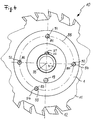
- the scoring tool 3 consists essentially of two Tool flanges 1 and 2, which together form a tool carrier 36 form. Each about half of the tool holder 36 representing tool flange 1 and 2 enters annular partial sheet 11 or 12, which together Form scoring saw blade 10. 4 is can be seen that the teeth of a partial sheet 11 in Direction of rotation in the gaps between the other's teeth Part 12 lie.
- the first tool flange 1 is axially displaceable a hub 4, which is part of the second tool flange 2 is.
- the Tool flange 2 and the hub 4 separate components, which - preferably with screws 5 - firmly connected are.
- the hub 4 shows at one axial end an annular flange 6, which is on an outer, from the first Tool flange 1 facing away from the end face 7 of the annular second tool flange 2 rests.
- the hub 4 protrudes the second tool flange 2.
- the ring flange is preferred 6 over most of its thickness d in one Countersink 8 included in the radially inner Area of the outer end face 7 of the second tool flange 2 is formed.
- the screws 5 arranged in threaded holes 9 of the second tool flange 2 intervene.
- the screws 5 and their associated Threaded holes 9 over the circumference of the rotationally symmetrical, second tool flange 2 preferred equally distributed; are in the embodiment shown Four screws 5 or threaded holes 9 over the circumference with equidistant circumferential distances from each other arranged on a common circle 16.
- a head 21 End of a threaded spindle 20 of an adjusting device 35 is a head 21 End of a threaded spindle 20 of an adjusting device 35.
- the preferred as a threaded bolt or screw executed threaded spindle 20 is parallel to Axis of rotation 33 of the scribing tool 3 and extends through one unthreaded axial bore 13 in the second tool flange 2 is introduced.
- the bore axis 14 (FIG. 5) lies below the inner edge 15 of the second Tool flange 2 worn on its inner end face Sub-sheet 12. It may be appropriate to the central axis 14 the bore 13 approximately on the common circle 16 to be arranged on which the central axes 17 of the screws 5 or the threaded holes 9 are. In particular, the Bore 13 closer to the hub 4 than on the outer circumference 18 of the second tool flange 2.
- the head 21 is located in the Threaded spindle 20 essentially completely in one Countersink 23, on the bottom 22 of which facing him Annular surface of the head 21 rests.
- the depth t of the countersink 23 is equal to that Height h of head 21; the depth t is preferably slight larger, so that the head 21 is axially essentially free of play, but rotatable between the second tool flange 2 and the an annular flange 6 of the hub 4 forming a cover disk is held.
- the threaded spindle 20 extends through the unthreaded bore 13 in the direction of the first tool flange 1 and engages in a threaded bore 19, the as an axial through hole in the first tool flange 1 is formed parallel to the axis of rotation 33 and the is coaxial with the bore 13.
- a threaded hole 19 lying end 24 of the threaded spindle 20 is one Recording 25 for engaging a tool such as one Key or the like. Provided so that with the tool the threaded spindle 20 can be easily rotated.
- the basic body of the first tool flange 1 is - likewise like the base body of the second tool flange 2 - in essentially rotationally symmetrical and has an outer circumference 30 on the outer circumference 18 of the second tool flange 2 a common surface of revolution forms.
- the first tool flange 1 has an inner cylindrical receptacle 31, in which the hub in engages essentially free of play and slidably.
- the axial length L of the hub 4 is longer than the axial Length l of the inner, sleeve-shaped receptacle 31 is provided.
- the receptacle 31 of the first Tool flange 1 axially through an inner sleeve shoulder 32 extended with radial play in the ring-shaped, engages second tool flange 2 and - approximately with the Distance a - ends in front of the ring flange 6.
- the hub 4 For the rotationally fixed connection of the two tool flanges 1 and 2, the hub 4 carries a rotary driver 26, which is in a axial coupling groove 27 of the inner receptacle 31 of the first Tool flange 1 engages.
- the clutch groove 27 advantageously extends axially over the entire length of the Recording 31 and is on the two faces of the first Tool flange 1 open.
- the rotary driver 26 is preferably a radially over the outer circumference of the hub 4 protruding part of axially limited length, which the expected loads is designed accordingly.
- the Rotary driver 26 can be one of the hub 4 and the first Tool flange 1 be a separate component, which in the The outer circumference of the hub 4 can be inserted captively.
- the tool flanges bear on their mutually facing end faces 1 and 2 a partial sheet 11 and 12 of the Scoring saw blade 10.
- the partial blades 11 and 12 are as Ring blades are formed, which are open radially outwards Countersinks 28 and 29 in the facing ends of the Tool halves 1 and 2 are inserted.
- Each sheet 11 and 12 is with fasteners on respective tool flange 1 and 2 rotatably and axially captive, but interchangeably attached.
- fasteners 40 to 43 or 50 to 53 are provided, each in threaded holes 44 and 54 (Fig. 3) of the tool flanges Intervene 1 and 2.
- the threaded holes 44 or the passage openings provided in the partial sheet 12 70 to 73 have 33 parallel to the axis of rotation lying central axes 80 to 83 and are over the circumference distributed preferably arranged on a common circle 45.
- the central axes are 80 to 82 Fasteners in the circumferential direction with equidistant Distance m to one another (FIG.
- the location of the fasteners or central axes 83 the circle 45 and - if necessary - radial to The axis of rotation 33 of the scoring tool 3 is based on balancing criteria of the overall arrangement. That is the partial sheet 12 on the tool flange 2 holding fasteners (Screw 43, opening 73, threaded hole 44 - FIG. 5) thus forms a constructive balance weight for the Overall arrangement of the scribing tool 3.
- the Threaded bore 44 is longer than the screw 43.
- the partial sheet 12 over the circumference with several, preferably four screws 40 to 43 on the tool flange 2 are defined about the circumference of the tool flange 2 four threaded holes 44 formed by the respective screw 40 to 43 only partially filled will.
- the arranged asymmetrically to the axis of rotation 33 according to the invention Threaded holes 44 of the fasteners thus effect balancing the tool carrier 36 itself.
- one or more Pass-through openings deviate from the circular shape Have shape.
- the access opening 73 in 7 is a kidney-shaped or elliptical shape shown in dashed lines.
- the one introduced into the edge of the opening 72 Radial slot can be of suitable length, width and position and in particular over the entire axial length of the through opening run.
- the cutting width SR of the scoring saw blade 10 becomes the threaded spindle 20 by engagement of a tool in the externally accessible receptacle 25 of the threaded spindle turned.
- the rotatable in the second tool flange 2 causes axially non-displaceable threaded spindle 20 a corresponding to the pitch of the thread caused axial displacement of the first tool flange 1 on the hub 4, which changes the cutting width SR. 1 is approximately the maximum possible cutting width SR shown.
- the threaded spindle is located 20 in a non-threaded bore 13 of the second tool flange 2; it may be appropriate to bore 13 as Form the threaded hole and the threaded spindle on the one half with a right-hand thread and the other Half with a left-hand thread.
- the threaded spindle then takes place both in the bore 13 and in the bore 19 an adjustment stroke through which the Distance a between the two tool flanges 1 and 2 and thus the Cutting width SR of the scoring saw blade 10 is changeable.
- the thread pitch very be chosen flat, so that a sensitive, against axial forces insensitive adjusting device 35 is formed.
- the circumference is asymmetrical to the other fasteners arranged fasteners (screw 43, 53) is preferably adjacent to the adjustment device 35 or their threaded bolts 20. It can be advantageous be to further balance the overall arrangement Screws 40 to 43, 50 to 53 receiving Threaded holes 44, 54 with different excess lengths to execute. The excess lengths can according to the on-site the fasteners necessary for balancing material removal be measured. It may be sufficient to symmetrical arrangement of the fasteners Balancing of the overall arrangement exclusively via the To achieve design of the excess lengths of the threaded holes.
Landscapes
- Life Sciences & Earth Sciences (AREA)
- Engineering & Computer Science (AREA)
- Mechanical Engineering (AREA)
- Wood Science & Technology (AREA)
- Forests & Forestry (AREA)
- Sawing (AREA)
- Knives (AREA)
- Details Of Cutting Devices (AREA)
Description
- Fig. 1
- eine schematische Darstellung einer Kreissägemaschine mit einem Ritzwerkzeug,
- Fig. 2
- eine schematische Draufsicht auf eine Kreissägemaschine nach Fig. 1,
- Fig. 3
- einen Schnitt durch ein erfindungsgemäßes Ritzwerkzeug aus einem Werkzeugträger und einem Ritzsägeblatt,
- Fig. 4
- eine Ansicht auf das Ritzwerkzeug gemäß Pfeil Y in Fig. 3,
- Fig. 5
- eine Ansicht auf die Innenseite eines Werkzeugflansches mit darauf befestigtem Teilblatt gemäß Pfeil Y in Fig. 3,
- Fig. 6
- in vergrößerter Darstellung ein Befestigungsmittel zur Anordnung eines Teilblattes auf einem Werkzeugflansch,
- Fig. 7
- eine Ansicht eines Teilblattes des Ritzsägeblattes.
Claims (14)
- Ritzwerkzeug für eine Kreissägemaschine, insbesondere für eine Formatkreissäge, bestehend aus einem Werkzeugträger (36) und einem Ritzsägeblatt (10), wobei der Werkzeugträger (36) aus zwei gleichachsig zueinander angeordneten und axial zueinander verstellbaren Werkzeugflanschen (1, 2) besteht und das Ritzsägeblatt (10) aus zwei Teilblättern (11, 12) zusammengesetzt ist, wobei jedes Teilblatt (11, 12) mit über den Umfang verteilten Befestigungsmitteln auf einem zugeordneten Werkzeugflansch (1, 2) lösbar befestigt ist und beide Werkzeugflansche (1, 2) über eine Verstelleinrichtung (35) miteinander verbunden sind,
dadurch gekennzeichnet, daß die Verstelleinrichtung (35) im Werkzeugträger (36) selbst angeordnet ist und zum Auswuchten des Ritzwerkzeuges (3) mindestens ein Befestigungsmittel (43, 44, 73; 53, 54, 73) nach Auswuchtkriterien versetzt zu den anderen Befestigungsmitteln (40, 44, 70; 41, 44, 71; 42, 44, 72; 50, 54, 70; 51, 54, 71; 52, 54, 72) angeordnet ist. - Ritzwerkzeug nach Anspruch 1,
dadurch gekennzeichnet, daß die Mittelachsen (80 bis 83) der Befestigungsmittel auf einem gemeinsamen Kreis (45, 55) um die Drehachse (33) des Ritzwerkzeuges (3) liegen und zumindest die Mittelachse (83) eines Befestigungsmittels (43, 44, 73; 53, 54, 73) mit unterschiedlichem Abstand (m1, m2) zu den Mittelachsen (80, 81, 82) benachbarter Befestigungsmittel (40, 44, 70; 41, 44, 71; 42, 44, 72; 50, 54, 70; 51, 54, 71; 52, 54, 72) liegt. - Ritzwerkzeug nach Anspruch 1 oder 2,
dadurch gekennzeichnet, daß die Befestigungsmittel Schrauben (40, 41, 42, 43; 50, 51, 52, 53) sind, die Öffnungen im Teilblatt (11, 12) durchragen und in Gewindebohrungen (44, 45) des Werkzeugflansches (1, 2) eingreifen. - Ritzwerkzeug nach Anspruch 3,
dadurch gekennzeichnet, daß die Schrauben (40, 41, 42, 43; 50, 41, 52, 53) einen Senkkopf (49) haben, der versenkt in einer Ansenkung (77) der Durchgriffsöffnung (70 bis 73) des Teilblattes (11, 12) liegt. - Ritzwerkzeug nach Anspruch 4,
dadurch gekennzeichnet, daß die Ansenkung (77) größer als der Senkkopf (49) ausgebildet ist. - Ritzwerkzeug nach einem der Ansprüche 1 bis 5,
dadurch gekennzeichnet, daß die Mittelachsen (80, 81, 82, 83) der Befestigungsmittel beider Teilblätter (11, 12) einander gleichachsig gegenüberliegen. - Ritzwerkzeug nach einem der Ansprüche 1 bis 5,
dadurch gekennzeichnet, daß der erste Werkzeugflansch (1) auf einer Nabe des zweiten Werkzeugflansches (2) axial verschiebbar gehalten ist und vorzugsweise die Nabe (4) mit einem Drehmitnehmer (26) in den verschiebbar gehaltenen ersten Werkzeugflansch (1) eingreift. - Ritzwerkzeug nach Anspruch 7,
dadurch gekennzeichnet, daß die Nabe (4) und der zweite Werkzeugflansch (2) getrennte Bauteile sind, wobei vorzugsweise die Nabe (4) mit einem Ringflansch (6) versehen ist, der an der äußeren Stirnseite (7) der zweiten Werkzeughälfte (2) anliegt und auf dieser Stirnseite befestigt ist. - Ritzwerkzeug nach einem der Ansprüche 1 bis 8,
dadurch gekennzeichnet, daß die Verstelleinrichtung (35) eine Gewindespindel (20) ist, die vorzugsweise in den ersten Werkzeugflansch (1) eingeschraubt und in dem zweiten Werkzeugflansch (2) drehbar gehalten ist, wobei die Gewindespindel (20) eine gewindelose Bohrung (13) des zweiten Werkzeugflansches (2) in Richtung auf den ersten Werkzeugflansch (1) durchragt und insbesondere auf der von dem ersten Werkzeugflansch (1) abgewandten Stirnseite (7) des zweiten Werkzeugflansches (2) mit einem Kopf (21) abgestützt ist. - Ritzwerkzeug nach Anspruch 9,
dadurch gekennzeichnet, daß der Kopf (21) zwischen einer Abdeckscheibe, vorzugsweise einem Ringflansch (6) einer Nabe (4), und der äußeren Stirnseite (7) des zweiten Werkzeugflansches (2) etwa spielfrei, aber drehbar gehalten ist. - Ritzsägeblatt zur Verwendung bei einem Ritzwerkzeug einer Kreissägemaschine, insbesondere einer Formatkreissäge, bestehend aus zwei Teilblättern (11, 12), wobei jedes Teilblatt (11, 12) über den Umfang verteilt Öffnungen (70, 71, 72, 73) zum Durchgriff von Befestigungsmitteln (40, 41, 42, 43; 50, 51, 52, 53) aufweist, mit denen jedes Teilblatt (11, 12) auf einem Werkzeugflansch (1, 2) festlegbar ist und die axial zueinander verstellbaren Werkzeugflansche (1, 2) über eine Verstelleinrichtung (35) miteinander verbunden sind,
dadurch gekennzeichnet, daß bei einem Ritzerwerkzeug nach einem der Ansprüche 1 bis 10 zum Auswuchten des Gesamtwerkzeuges (3) in einem Teilblatt (11, 12) mindestens eine Durchgriffsöffnung (73) nach Auswuchtkriterien versetzt zu den anderen Durchgriffsöffnungen (70, 71, 72) in diesem Teilblatt (11, 12) angeordnet ist. - Ritzsägeblatt nach Anspruch 11,
dadurch gekennzeichnet, daß eine Durchgriffsöffnung (70, 71, 72, 73) auf der dem tragenden Werkzeugflansch (1, 2) abgewandten Seite eine Ansenkung (77) zur Aufnahme des Kopfes (49) eines Befestigungsmittels aufweist, wobei die Ansenkung (77) zumindest geringfügig größer als zur vollständigen Aufnahme des Kopfes (49) notwendig ausgebildet ist. - Ritzsägeblatt nach Anspruch 11 oder 12,
dadurch gekennzeichnet, daß die Durchgriffsöffnungen (70, 71, 72, 73) auf einem gemeinsamen Kreis (45, 55) um die Drehachse (33) des Ritzsägeblattes (10) angeordnet sind und zumindest eine Durchgriffsöffnung (73) mit unterschiedlichem Abstand (m1, m2) zu den benachbarten Durchgriffsöffnungen (70, 72) liegt. - Ritzsägeblatt nach einem der Ansprüche 11 bis 13,
dadurch gekennzeichnet, daß die Durchgriffsöffnungen eine von der Kreisform abweichende Gestalt, insbesondere eine schlitzförmige, ellipsenförmige, bajonettförmige oder ähnliche Gestalt haben.
Applications Claiming Priority (3)
| Application Number | Priority Date | Filing Date | Title |
|---|---|---|---|
| EP95102715 | 1995-02-25 | ||
| EP95102715 | 1995-02-25 | ||
| PCT/EP1996/000747 WO1996026815A1 (de) | 1995-02-25 | 1996-02-23 | Ritzwerkzeug für eine kreissägemaschine und ritzsägeblatt hierfür |
Publications (2)
| Publication Number | Publication Date |
|---|---|
| EP0810915A1 EP0810915A1 (de) | 1997-12-10 |
| EP0810915B1 true EP0810915B1 (de) | 1998-10-28 |
Family
ID=8219014
Family Applications (1)
| Application Number | Title | Priority Date | Filing Date |
|---|---|---|---|
| EP96904853A Expired - Lifetime EP0810915B1 (de) | 1995-02-25 | 1996-02-23 | Ritzwerkzeug für eine kreissägemaschine und ritzsägeblatt hierfür |
Country Status (8)
| Country | Link |
|---|---|
| US (1) | US5996462A (de) |
| EP (1) | EP0810915B1 (de) |
| AT (1) | ATE172660T1 (de) |
| AU (1) | AU4879796A (de) |
| DE (1) | DE59600742D1 (de) |
| DK (1) | DK0810915T3 (de) |
| ES (1) | ES2122799T3 (de) |
| WO (1) | WO1996026815A1 (de) |
Families Citing this family (9)
| Publication number | Priority date | Publication date | Assignee | Title |
|---|---|---|---|---|
| DE10041210C2 (de) * | 1999-08-30 | 2002-07-11 | Otto Martin Maschb Gmbh Fa | Kreissägemaschine |
| US6898164B2 (en) * | 2001-01-25 | 2005-05-24 | Dphi Acquisitions, Inc. | Close tracking algorithm in a digital tracking servo system |
| SE521638C2 (sv) * | 2001-04-23 | 2003-11-18 | Globe Invent Ab | Metod för bearbetning av ett objekt, maskin och verktygsenhet för utförande av metoden |
| DE10302066A1 (de) * | 2003-01-21 | 2004-07-29 | Kolbus Gmbh & Co. Kg | Vorrichtung zum Trennsägen von Doppelnutzen |
| DE102006005253A1 (de) | 2006-02-02 | 2007-08-09 | Otto Martin Maschinenbau Gmbh & Co. Kg | Einstellverfahren für Vorritzsägeblätter |
| ITGE20070032A1 (it) * | 2007-03-14 | 2008-09-15 | Ts Tecnospamec S R L | Utensile da taglio. |
| CN201931158U (zh) * | 2010-11-30 | 2011-08-17 | 宁波黑松工具有限公司 | 双锯片切割机 |
| JP6777280B2 (ja) * | 2016-06-14 | 2020-10-28 | 株式会社トリガー | 回転切断刃 |
| CN114654026B (zh) * | 2022-04-02 | 2024-04-05 | 合肥四维数控设备有限责任公司 | 用于板材加工的多片切割机 |
Family Cites Families (10)
| Publication number | Priority date | Publication date | Assignee | Title |
|---|---|---|---|---|
| US2788812A (en) * | 1955-05-24 | 1957-04-16 | John W Jacobs | Adjustable multi-blade dado cutter |
| US3323567A (en) * | 1965-04-07 | 1967-06-06 | North American Products Corp | Cone hogger and trim saw unit |
| DE2348731C2 (de) * | 1973-09-28 | 1983-04-28 | Ledermann Gmbh + Co, 7240 Horb | Kantenbearbeitungswerkzeug |
| IT1001735B (it) * | 1973-11-13 | 1976-04-30 | Sanvito C | Fresa composta per la lavorazione di bordi |
| US4055204A (en) * | 1976-11-22 | 1977-10-25 | Lifetime Carbide Company | Adjustable wobble dado assembly having improved dynamic balance |
| US4177685A (en) * | 1978-02-13 | 1979-12-11 | Delancey Warren H | Pulley |
| IT1145521B (it) * | 1981-10-20 | 1986-11-05 | Giben Impianti Spa | Dispositivo incisore, particolarmente adatto per le macchine e per gli impianti adibiti alla sezionatura di pannelli di legno e/od in altro materiale |
| SE446319B (sv) * | 1982-01-07 | 1986-09-01 | Lennart Johannesson | Anordning vid delade fresar |
| IT1201689B (it) * | 1986-12-12 | 1989-02-02 | Giben Impianti Spa | Metodo ed apparato particolarmente per la sezionatura fine ed in due tempi di pannelli o pacchi di pannelli di legno e o d altro materiale |
| IT1213905B (it) * | 1987-09-24 | 1990-01-05 | Giben Impianti Spa | Metodo ed apparato per la sezionatura fine di pannelli o pacchi dipannelli con l impiego di una sola sega a disco |
-
1996
- 1996-02-23 EP EP96904853A patent/EP0810915B1/de not_active Expired - Lifetime
- 1996-02-23 AU AU48797/96A patent/AU4879796A/en not_active Abandoned
- 1996-02-23 US US08/913,377 patent/US5996462A/en not_active Expired - Fee Related
- 1996-02-23 DE DE59600742T patent/DE59600742D1/de not_active Expired - Lifetime
- 1996-02-23 DK DK96904853T patent/DK0810915T3/da active
- 1996-02-23 AT AT96904853T patent/ATE172660T1/de not_active IP Right Cessation
- 1996-02-23 WO PCT/EP1996/000747 patent/WO1996026815A1/de not_active Ceased
- 1996-02-23 ES ES96904853T patent/ES2122799T3/es not_active Expired - Lifetime
Also Published As
| Publication number | Publication date |
|---|---|
| US5996462A (en) | 1999-12-07 |
| ATE172660T1 (de) | 1998-11-15 |
| WO1996026815A1 (de) | 1996-09-06 |
| DK0810915T3 (da) | 1999-07-12 |
| AU4879796A (en) | 1996-09-18 |
| ES2122799T3 (es) | 1998-12-16 |
| EP0810915A1 (de) | 1997-12-10 |
| DE59600742D1 (de) | 1998-12-03 |
Similar Documents
| Publication | Publication Date | Title |
|---|---|---|
| DE1650937A1 (de) | Verbindungsvorrichtung | |
| DE1808138A1 (de) | Tischkreissaegemaschine | |
| DE8902716U1 (de) | Umlaufendes Schneidwerkzeug, insbesondere zum Stranggranulieren von Kunststoffen | |
| EP1615752B1 (de) | Messerkopf für fleischkutter | |
| EP0810915A1 (de) | Ritzwerkzeug für eine kreissägemaschine und ritzsägeblatt hierfür | |
| EP0131136B1 (de) | Kegelsenker | |
| DE102017110754B4 (de) | Werkzeugvorrichtung, insbesondere Fräswerkzeug | |
| EP1945367B1 (de) | Fleischkutter | |
| EP3795316A1 (de) | Werkzeugkopf eines bearbeitungswerkzeuges und wendeschneidplatte hierfür | |
| DE29504233U1 (de) | Ritzwerkzeug für eine Kreissägemaschine | |
| EP0266447B1 (de) | Rundlaufendes Schneidwerkzeug, insbesondere zum Stranggranulieren von Kunststoffen | |
| DE102015005787A1 (de) | Zerkleinerungseinheit für eine Zerkleinerungsvorrichtung zum Zerkleinern von Aufgabegut, insbesondere Messerkorb | |
| DE3120962C2 (de) | ||
| EP2845649B1 (de) | Schneideinrichtung | |
| EP2311568A1 (de) | Schneidsatz mit Sicherheitsdistanzringmesser | |
| DE3228671C2 (de) | Messerkopf für Profilzerspaner mit Kreissägesegmenten | |
| DE3043146A1 (de) | Messerkopf | |
| EP1520664B1 (de) | Einrichtung zum Beschneiden eines Druckproduktes | |
| DE4407379C2 (de) | Sägemaschine | |
| DE10315685A1 (de) | Klemmverbindung für eine fliegend auf einer Motorwelle gelagerte Pumpenwelle | |
| EP2001642B1 (de) | Maschine und werkzeug zum bearbeiten von werkstücken aus holz, kunststoff und dergleichen sowie werkzeug zum einsatz in einer solchen maschine | |
| DE102007060078B3 (de) | Räumvorrichtung | |
| DE102012106188B4 (de) | Verfahren zum Demontieren und Verfahren zum Montieren eines Schneidwerkzeugs einer Werkzeuganordnung zum Herstellen von Wandschlitzen | |
| DE19832499C2 (de) | Zerspanungswerkzeug | |
| DE3936883A1 (de) | Fraeskopf zur holzbearbeitung |
Legal Events
| Date | Code | Title | Description |
|---|---|---|---|
| PUAI | Public reference made under article 153(3) epc to a published international application that has entered the european phase |
Free format text: ORIGINAL CODE: 0009012 |
|
| 17P | Request for examination filed |
Effective date: 19970925 |
|
| AK | Designated contracting states |
Kind code of ref document: A1 Designated state(s): AT BE CH DE DK ES FR GB IT LI LU NL PT SE |
|
| GRAG | Despatch of communication of intention to grant |
Free format text: ORIGINAL CODE: EPIDOS AGRA |
|
| 17Q | First examination report despatched |
Effective date: 19980213 |
|
| GRAG | Despatch of communication of intention to grant |
Free format text: ORIGINAL CODE: EPIDOS AGRA |
|
| GRAH | Despatch of communication of intention to grant a patent |
Free format text: ORIGINAL CODE: EPIDOS IGRA |
|
| GRAH | Despatch of communication of intention to grant a patent |
Free format text: ORIGINAL CODE: EPIDOS IGRA |
|
| GRAA | (expected) grant |
Free format text: ORIGINAL CODE: 0009210 |
|
| STAA | Information on the status of an ep patent application or granted ep patent |
Free format text: STATUS: THE PATENT HAS BEEN GRANTED |
|
| AK | Designated contracting states |
Kind code of ref document: B1 Designated state(s): AT BE CH DE DK ES FR GB IT LI LU NL PT SE |
|
| REF | Corresponds to: |
Ref document number: 172660 Country of ref document: AT Date of ref document: 19981115 Kind code of ref document: T |
|
| REG | Reference to a national code |
Ref country code: CH Ref legal event code: NV Representative=s name: BUECHEL, VON REVY & PARTNER Ref country code: CH Ref legal event code: EP |
|
| REF | Corresponds to: |
Ref document number: 59600742 Country of ref document: DE Date of ref document: 19981203 |
|
| REG | Reference to a national code |
Ref country code: ES Ref legal event code: FG2A Ref document number: 2122799 Country of ref document: ES Kind code of ref document: T3 |
|
| PGFP | Annual fee paid to national office [announced via postgrant information from national office to epo] |
Ref country code: PT Payment date: 19990113 Year of fee payment: 4 |
|
| ITF | It: translation for a ep patent filed | ||
| GBT | Gb: translation of ep patent filed (gb section 77(6)(a)/1977) |
Effective date: 19990120 |
|
| ET | Fr: translation filed | ||
| PG25 | Lapsed in a contracting state [announced via postgrant information from national office to epo] |
Ref country code: LU Free format text: LAPSE BECAUSE OF NON-PAYMENT OF DUE FEES Effective date: 19990223 |
|
| PGFP | Annual fee paid to national office [announced via postgrant information from national office to epo] |
Ref country code: BE Payment date: 19990224 Year of fee payment: 4 |
|
| REG | Reference to a national code |
Ref country code: PT Ref legal event code: SC4A Free format text: AVAILABILITY OF NATIONAL TRANSLATION Effective date: 19981028 |
|
| REG | Reference to a national code |
Ref country code: DK Ref legal event code: T3 |
|
| PLAV | Examination of admissibility of opposition |
Free format text: ORIGINAL CODE: EPIDOS OPEX |
|
| PLBI | Opposition filed |
Free format text: ORIGINAL CODE: 0009260 |
|
| PLAV | Examination of admissibility of opposition |
Free format text: ORIGINAL CODE: EPIDOS OPEX |
|
| 26 | Opposition filed |
Opponent name: GUHDO-WERK HERBERT DOERKEN GMBH + CO KG Effective date: 19990728 |
|
| NLR1 | Nl: opposition has been filed with the epo |
Opponent name: CO KG Opponent name: GUHDO-WERK HERBERT DOERKEN GMBH |
|
| PLBG | Opposition deemed not to have been filed |
Free format text: ORIGINAL CODE: 0009274 |
|
| 26D | Opposition deemed not to have been filed |
Opponent name: GUHDO-WERK HERBERT DOERKEN GMBH + CO KG Effective date: 19990916 |
|
| PG25 | Lapsed in a contracting state [announced via postgrant information from national office to epo] |
Ref country code: BE Free format text: LAPSE BECAUSE OF NON-PAYMENT OF DUE FEES Effective date: 20000228 |
|
| NLXE | Nl: other communications concerning ep-patents (part 3 heading xe) |
Free format text: PAT. BUL. 12/99: THE OPPOSITION SHOULD BE DEEMED NOT TO HAVE BEEN FILED (SEE EUROPEAN PATENT BULLETIN 02.02.2000/05). |
|
| BERE | Be: lapsed |
Owner name: LEDERMANN G.M.B.H. Effective date: 20000228 |
|
| PG25 | Lapsed in a contracting state [announced via postgrant information from national office to epo] |
Ref country code: PT Free format text: LAPSE BECAUSE OF NON-PAYMENT OF DUE FEES Effective date: 20000831 |
|
| PG25 | Lapsed in a contracting state [announced via postgrant information from national office to epo] |
Ref country code: NL Free format text: LAPSE BECAUSE OF NON-PAYMENT OF DUE FEES Effective date: 20000901 |
|
| NLV4 | Nl: lapsed or anulled due to non-payment of the annual fee |
Effective date: 20000901 |
|
| REG | Reference to a national code |
Ref country code: PT Ref legal event code: MM4A Free format text: LAPSE DUE TO NON-PAYMENT OF FEES Effective date: 20000831 |
|
| PGFP | Annual fee paid to national office [announced via postgrant information from national office to epo] |
Ref country code: SE Payment date: 20010205 Year of fee payment: 6 Ref country code: DK Payment date: 20010205 Year of fee payment: 6 |
|
| REG | Reference to a national code |
Ref country code: GB Ref legal event code: IF02 |
|
| PG25 | Lapsed in a contracting state [announced via postgrant information from national office to epo] |
Ref country code: SE Free format text: LAPSE BECAUSE OF NON-PAYMENT OF DUE FEES Effective date: 20020224 |
|
| PG25 | Lapsed in a contracting state [announced via postgrant information from national office to epo] |
Ref country code: DK Free format text: LAPSE BECAUSE OF NON-PAYMENT OF DUE FEES Effective date: 20020228 |
|
| EUG | Se: european patent has lapsed |
Ref document number: 96904853.7 |
|
| REG | Reference to a national code |
Ref country code: DK Ref legal event code: EBP |
|
| PGFP | Annual fee paid to national office [announced via postgrant information from national office to epo] |
Ref country code: ES Payment date: 20100222 Year of fee payment: 15 Ref country code: CH Payment date: 20100223 Year of fee payment: 15 |
|
| PGFP | Annual fee paid to national office [announced via postgrant information from national office to epo] |
Ref country code: IT Payment date: 20100219 Year of fee payment: 15 Ref country code: FR Payment date: 20100226 Year of fee payment: 15 |
|
| PGFP | Annual fee paid to national office [announced via postgrant information from national office to epo] |
Ref country code: GB Payment date: 20100218 Year of fee payment: 15 Ref country code: AT Payment date: 20100212 Year of fee payment: 15 |
|
| REG | Reference to a national code |
Ref country code: CH Ref legal event code: PL |
|
| GBPC | Gb: european patent ceased through non-payment of renewal fee |
Effective date: 20110223 |
|
| PG25 | Lapsed in a contracting state [announced via postgrant information from national office to epo] |
Ref country code: LI Free format text: LAPSE BECAUSE OF NON-PAYMENT OF DUE FEES Effective date: 20110228 Ref country code: CH Free format text: LAPSE BECAUSE OF NON-PAYMENT OF DUE FEES Effective date: 20110228 |
|
| REG | Reference to a national code |
Ref country code: FR Ref legal event code: ST Effective date: 20111102 |
|
| PG25 | Lapsed in a contracting state [announced via postgrant information from national office to epo] |
Ref country code: AT Free format text: LAPSE BECAUSE OF NON-PAYMENT OF DUE FEES Effective date: 20110223 |
|
| PG25 | Lapsed in a contracting state [announced via postgrant information from national office to epo] |
Ref country code: IT Free format text: LAPSE BECAUSE OF NON-PAYMENT OF DUE FEES Effective date: 20110223 |
|
| PG25 | Lapsed in a contracting state [announced via postgrant information from national office to epo] |
Ref country code: FR Free format text: LAPSE BECAUSE OF NON-PAYMENT OF DUE FEES Effective date: 20110228 |
|
| PG25 | Lapsed in a contracting state [announced via postgrant information from national office to epo] |
Ref country code: GB Free format text: LAPSE BECAUSE OF NON-PAYMENT OF DUE FEES Effective date: 20110223 |
|
| REG | Reference to a national code |
Ref country code: ES Ref legal event code: FD2A Effective date: 20120411 |
|
| PG25 | Lapsed in a contracting state [announced via postgrant information from national office to epo] |
Ref country code: ES Free format text: LAPSE BECAUSE OF NON-PAYMENT OF DUE FEES Effective date: 20110224 |
|
| PGFP | Annual fee paid to national office [announced via postgrant information from national office to epo] |
Ref country code: DE Payment date: 20130219 Year of fee payment: 18 |
|
| REG | Reference to a national code |
Ref country code: DE Ref legal event code: R119 Ref document number: 59600742 Country of ref document: DE |
|
| REG | Reference to a national code |
Ref country code: DE Ref legal event code: R119 Ref document number: 59600742 Country of ref document: DE Effective date: 20140902 |
|
| PG25 | Lapsed in a contracting state [announced via postgrant information from national office to epo] |
Ref country code: DE Free format text: LAPSE BECAUSE OF NON-PAYMENT OF DUE FEES Effective date: 20140902 |