EP0809056B1 - Sanitärarmatur - Google Patents
Sanitärarmatur Download PDFInfo
- Publication number
- EP0809056B1 EP0809056B1 EP97108246A EP97108246A EP0809056B1 EP 0809056 B1 EP0809056 B1 EP 0809056B1 EP 97108246 A EP97108246 A EP 97108246A EP 97108246 A EP97108246 A EP 97108246A EP 0809056 B1 EP0809056 B1 EP 0809056B1
- Authority
- EP
- European Patent Office
- Prior art keywords
- valve system
- sanitary fitting
- base
- fitting according
- nipple
- Prior art date
- Legal status (The legal status is an assumption and is not a legal conclusion. Google has not performed a legal analysis and makes no representation as to the accuracy of the status listed.)
- Expired - Lifetime
Links
- 210000002445 nipple Anatomy 0.000 claims abstract description 25
- XLYOFNOQVPJJNP-UHFFFAOYSA-N water Substances O XLYOFNOQVPJJNP-UHFFFAOYSA-N 0.000 claims abstract description 16
- 238000004519 manufacturing process Methods 0.000 description 6
- 238000011161 development Methods 0.000 description 4
- 230000018109 developmental process Effects 0.000 description 4
- RYGMFSIKBFXOCR-UHFFFAOYSA-N Copper Chemical compound [Cu] RYGMFSIKBFXOCR-UHFFFAOYSA-N 0.000 description 2
- 238000013459 approach Methods 0.000 description 2
- 229910052802 copper Inorganic materials 0.000 description 2
- 239000010949 copper Substances 0.000 description 2
- 239000007787 solid Substances 0.000 description 2
- 229910001018 Cast iron Inorganic materials 0.000 description 1
- 230000001419 dependent effect Effects 0.000 description 1
- 239000002689 soil Substances 0.000 description 1
- 238000009423 ventilation Methods 0.000 description 1
Images

Classifications
-
- F—MECHANICAL ENGINEERING; LIGHTING; HEATING; WEAPONS; BLASTING
- F16—ENGINEERING ELEMENTS AND UNITS; GENERAL MEASURES FOR PRODUCING AND MAINTAINING EFFECTIVE FUNCTIONING OF MACHINES OR INSTALLATIONS; THERMAL INSULATION IN GENERAL
- F16K—VALVES; TAPS; COCKS; ACTUATING-FLOATS; DEVICES FOR VENTING OR AERATING
- F16K27/00—Construction of housing; Use of materials therefor
- F16K27/04—Construction of housing; Use of materials therefor of sliding valves
- F16K27/044—Construction of housing; Use of materials therefor of sliding valves slide valves with flat obturating members
- F16K27/045—Construction of housing; Use of materials therefor of sliding valves slide valves with flat obturating members with pivotal obturating members
Definitions
- the invention is based on a sanitary fitting with a Fitting body in which a receiving space for receiving a Valve system, in particular a mixing cartridge is.
- the recording space is cast by a solid Bottom limited, which is usually part of the body of the valve is. Through this solid floor, the pipes screwed, soldered or plugged in. Lies on the floor if necessary with the interposition of an adapter plate the valve system on.
- a sanitary fitting is already known (DE-A1-35 13 840), in which a Fitting body insertable floor for attaching supply lines and for attaching a threaded rod is used. With this threaded rod, the valve body is attached to one Underlay clamped.
- the invention has for its object a possibility create the valve body, which is usually made of cast iron is to simplify.
- the invention proposes a sanitary fitting with the features mentioned in claim 1. Further developments the invention are the subject of dependent claims.
- valve body Due to the separate production of the floor, which is a very can have simple geometric shape, simplified the production.
- the valve body needs to fix of the bottom to have only small projections, so that the valve body is also easier to manufacture.
- the floor When installing, for example, the floor is first in the Fitting body and then the valve system, which is a standardized mixer cartridge can. It may be sufficient to fix the floor if this is applied to system knobs and by setting the Mixer cartridge is also specified.
- the valve system which is a standardized mixer cartridge can. It may be sufficient to fix the floor if this is applied to system knobs and by setting the Mixer cartridge is also specified.
- the floor closes the recording room.
- it can rest on individual or continuous narrow projections.
- the Bottom forms a support surface for the valve system, for example especially for the mentioned end face of the valve system, in which the at least one water passage opening opens.
- the water passes through a supply line the bottom to the opening of the valve system.
- Water can be run through the floor.
- the invention proposes that at least one pass the bottom of a connecting line can be connected. It is conceivable, for example, that the bottom has a nipple for Connection of a connecting line, for example a screw connection having. In this case, the passage of the floor directly with the water outlet opening of the valve system stay in contact.
- the invention proposes that in the passage of the floor a connecting line provided with a nipple can be used is. Then the water flows from the nipple provided connecting line directly to the valve system, wherein a seal between the nipple and the valve system is provided becomes.
- the nipple over the projecting surface of the floor facing the valve system and engages in an opening of the valve system.
- a seal between the nipple and the valve system is provided his,
- valve system has a projection has the nipple-like in the passage or a engages the recess surrounding the passage of the floor.
- the nipple can be arranged at the end of a pipeline, So for example a copper tube that is usually used for Connection of sanitary fittings is used.
- the nipple at the end of a Supply hose is arranged. This is particularly so makes sense for more complicated shapes, because then the hose from the side of the valve through the opening of the element on which the sanitary fitting is to be attached, inserted and can be threaded.
- the floor is a passage for the has mixed water leaving the mixing system. This can be done either cross the floor in a direction similar to the feed line, d. H. from one end face to the other end face. But it is also possible that the feed-through for the mixed water leaves the ground on the side, i.e. with one cylindrical receiving space in the lateral surface of the floor.
- the floor can be approximately disc-shaped with flat surfaces Boundary surfaces can be formed.
- the floor is a separate, factory-made and assembled Component of the sanitary fitting.
- valve leads to an outlet Outlet line in one piece with the bottom or with one of the several parts of the Soil is formed.
- the invention proposes the supply lines and the floor and possibly also the outlet lines Manufacture pre-assembled.
- valve system on the Floor is fixed, which in turn can be fixed to the base body of the fitting.
- FIG. 1 shows simplified a sanitary fitting in its essential parts.
- the sanitary fitting contains a fitting base body 1, which is approximately cylindrical in the example shown and forms an outlet 2 on its right-hand cylindrical jacket surface in FIG. 1. At the end of the outlet 2, not shown, an outlet opening is arranged, from which the water leaving the fitting emerges.
- the valve body 1 is hollow on the inside and also has one cylindrical receiving space 3, which in the illustrated Embodiment essentially entirely of a valve system 4 is filled.
- the receiving space 3 of the fitting body 1 is included provided with an internal thread 5 into which a cap 6 is screwed is.
- the cap 6 places the mixing system 5 in the valve body 1 fixed.
- a shaft 7 on which an operating handle is attached can be.
- the fitting body 1 At the end of the receiving space 3, the fitting body 1 a circumferential, only slightly projecting inwards Rib 8 on. Instead of a circumferential rib 8 could also there may be individual projections.
- the rib 8 forms one circumferential shoulder lying in one plane 9. The shoulder 9 is to the outer end closable by the cap 6 the recording room 3 directed.
- a base 10 is placed on the shoulder 9, the outer circumference thereof corresponds to the inner circumference of the receiving space 3. He therefore fills the receiving space 3 substantially completely and is set in this way in the transverse direction.
- the floor 10 has two passages 11, which on the in Fig. 1 lower side 12 of the bottom 10, i.e. on the the valve system 4 opposite side of the bottom 10, each with one Lead 13 are connected. With the supply lines 13 it can For example, copper pipes are in the openings of the bottom 10 pushed into contact with the constriction 14 and soldered to the bottom 10.
- the side of the valve system 4 facing the floor 10 contains another opening 17 through a transverse channel with a side opening 18 of the receiving space in Connection is established so that the valve system 4 leaving Mixed water can reach outlet 2 via openings 17 and 18 can.
- the assembly of the sanitary fitting according to Fig. 1 happens such that in the cast fitting body 1 first of above, i.e. from the direction of the internal thread 5, which with the leads 13 provided bottom 10 is used until it is on the shoulder 9 comes to rest. Then the valve system 4 used from the same direction until its Approaches 16 engage in the widened passages 11. Subsequently the cap 6 is placed and into the internal thread 5 screwed in.
- Fig. 2 shows another type of on an enlarged scale Execution of a supply line through the floor 10.
- the floor 10 in turn has a passage 11, which as Stepped bore is formed, the part with an enlarged Diameter directed into the interior of the receiving space 3 is.
- the feed line 13 has a nipple 19 in the region of its end on.
- This nipple contains an outer diameter that the Corresponds to the inner diameter of the enlarged part of the passage 11.
- the nipple 19 has two circumferential grooves 20, a groove 20 of which comes to rest in the passage 11, while the second groove 20 is outside the bottom 10. Both Grooves are intended to receive one O-ring 21 each.
- the bottom 10 also has a circumferential surface in its outer surface 22 Groove 23 in which an O-ring is inserted. This O-ring seals against the valve body 1.
- valve system 4 which in its end surface depressions has, the inner diameter of the outer diameter of the Nipple 19 corresponds.
- the receiving space 3 is substantially cylindrical and from the mixing system 4 is completely filled, so that the mixing system 4 by the entire recording space is centered on the in Fig. 3 shown embodiment of the receiving space 3 differently designed.
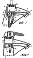
- the receiving space 3 in the embodiment 3 and 4 again contains an upward Opening 25 through which the schematically shown mixing system 4 can be used.
- the centering is done by a screw-in cap 26 which with its screw-in end 28 Valve system 4 surrounds on all sides.
- the transverse wall 31 has an inside with a thread provided neck 32, into which a threaded rod 33 is screwed is. This is used to fasten the valve body.
- a floor 34 On the top of the transverse wall 31 there is a floor 34 which contains a passage 35. In the passage 35 is a supply hose 36 inserted from above, in the area of his End a nipple 37 similar to the nipple 19 of FIG. 2 having.
- the bottom 34 is constructed in two parts and contains a first disc-shaped part 38. This lies flat on the transverse wall 31 on. Via the upper valve system 4 facing Side 39 of the disk part 38 protrudes from the nipple 37. With the second part 40 is connected to the disk-shaped part 38, which surrounds the disk part 38 on all sides and opposite it is sealed. The second part 40 of the bottom 34 forms a kind of hood over the disc part 38, through which not only the water supply with the hose 36 he follows. Also the mixed water leaving the valve system 4 passes through an opening 41 in the valve system 4 facing End face of the second part 40 in this hood-like Part and from there behind the drawing plane into that Interior of the outlet line 42, which is integral to the upper Part 40 of the bottom 34 is formed. The outlet line 42 extends to the end of the outlet spout 43. There the Outlet line 42 an outlet mouthpiece 44 with a ventilation device on. This outlet mouthpiece 44 is direct screwed onto the outlet line 42.
- the transverse wall 31 of the valve body 1 contains an opening, to lie in the assembled state of the connecting hose comes.
- This opening 45 is to the outside, i.e. in Fig. 3 to the right, open. This enables the pre-assembled, bottom 34 provided with hose 36 to be inserted laterally into the receiving space 3.
- Fig. 4 shows an embodiment, that of the embodiment 3 is very similar, so that only the differences being represented.
- transverse wall 46 which is also parallel to the bearing surface 30 of the Fitting body runs.
- This transverse wall 46 has a central one Opening 47 so that around the opening 47 a circumferential Shoulder 48 is formed, on which the bottom 34 rests.
- the one in Fig. 4 must first Invisible lower end of the hose 36 and the second Not shown supply hose through the opening 47 and then the bottom 34 from the side in the recording room 3 are introduced.
- the attachment via the valve system 4 and the nut 26 in again the same way as in the embodiment Fig. 3.
Landscapes
- Engineering & Computer Science (AREA)
- General Engineering & Computer Science (AREA)
- Mechanical Engineering (AREA)
- Valve Housings (AREA)
- Multiple-Way Valves (AREA)
- Domestic Plumbing Installations (AREA)
- Infusion, Injection, And Reservoir Apparatuses (AREA)
- Percussion Or Vibration Massage (AREA)
- Bidet-Like Cleaning Device And Other Flush Toilet Accessories (AREA)
- Supports For Pipes And Cables (AREA)
Description
- Fig. 1
- einen Teilschnitt durch eine Sanitärarmatur;
- Fig. 2
- in vergrößertem Maßstab eine teilweise geschnittene Seitenansicht des Bodens mit einer mit einem Nippel versehenen Anschlussleitung;
- Fig. 3
- einen Schnitt durch eine weitere Sanitärarmatur nach der Erfindung;
- Fig. 4
- einen Schnitt durch eine nochmals weitere Ausführungsform einer Sanitärarmatur.
Fig. 1 zeigt vereinfacht eine Sanitärarmatur in ihren wesentlichen Teilen. Die Sanitärarmatur enthält einen Armaturengrundkörper 1, der im dargestellten Beispiel etwa zylindrisch ausgebildet ist und an seiner in Fig. 1 rechten Zylindermantelfläche einen Auslauf 2 bildet. Am nicht dargestellten Ende des Auslaufs 2 ist eine Auslauföffnung angeordnet, aus der das die Armatur verlassende Wasser austritt.
Claims (16)
- Sanitärarmatur, mit1.1 einem Armaturenkörper (1),1.2 einem in diesem ausgebildeten, zur Aufnahme eines Ventilsystems (4) bestimmten Aufnahmeraum (3),1.3 einem in den Aufnahmeraum (3) einsetzbaren Ventilsystem (4), das1.3.1 im Bereich seiner inneren Endfläche mindestens eine Wasserdurchtrittsöffnung aufweist, sowie mit1.4 einem der inneren Enfläche des Ventilsystems (4) zugeordneten Boden (10, 34), der1.4.1 mindestens einen der Wasserdurchtrittsöffnung des Ventil systems (4) zugeordneten Durchgang (11, 35) aufweist,1.4.2 als getrenntes Bauteil ausgebildet und1.4.3 in den Aufnahmeraum (3) einsetzbar ist, sowie mit1.5 einer zu einem Auslauf (43) der Armatur führenden Auslaufleitung (42), dadurch gekennzeichnet, dass1.6 die Auslaufleitung (42) einstückig mit dem Boden (34) bzw. einem Teil (40) des Bodens (34) ausgebildet ist.
- Sanitärarmatur nach Anspruch 1, bei der der Boden (10, 34) den Aufnahmeraum (3) abschließt.
- Sanitärarmatur nach Anspruch 1 oder 2, bei der der Boden (10, 34) eine Auflagefläche für das Ventilsystem (4) bildet, insbesondere für dessen Endfläche.
- Sanitärarmatur nach einem der vorhergehenden Ansprüche, bei der an dem mindestens einen Durchgang (11, 35) des Bodens (10, 34) eine Anschlussleitung anschließbar ist.
- Sanitärarmatur nach einem der vorhergehenden Ansprüche, bei der in den Durchgang (11, 35) des Bodens (10, 34) eine mit einem Nippel (19, 37) versehene Anschlussleitung (13, 36) einsetzbar ist.
- Sanitärarmatur nach Anspruch 5, bei der der Nippel (19) über die dem Ventilsystem (4) zugewandte Fläche (15) des Bodens (10) vorspringt und ggf. in eine Öffnung des Ventilsystems (4) eingreift.
- Sanitärarmatur nach Anspruch 5 oder 6, bei der der Nippel (19) eine Ausrichtung des Ventilsystems (4) bewirkt.
- Sanitärarmatur nach einem der Ansprüche 5 bis 7, bei der der Nippel (19, 37) das Ende einer Rohrleitung (13) bildet.
- Sanitärarmatur nach einem der Ansprüche 5 bis 7, bei der der Nippel (37) das Ende eines Schlauches (36) bildet.
- Sanitärarmatur nach einem der vorhergehenden Ansprüche, bei der der Boden (10) durch die gleiche Öffnung in den Aufnahmeraum (3) des Armaturenkörpers (1) einsetzbar ist wie das Ventilsystem (4).
- Sanitärarmatur nach einem der Ansprüche 1 bis 9, bei der der Boden (34) seitlich in den Aufnahmeraum (3) des Armaturenkörpers (1) einsetzbar, insbesondere einschiebbar, ist.
- Sanitärarmatur nach einem der vorhergehenden Ansprüche, bei der der Boden (34) eine Durchführung für das das Ventilsystem (4) verlassende Mischwasser aufweist.
- Sanitärarmatur nach einem der vorhergehenden Ansprüche, bei der der Boden (34) aus zwei Teilen (38, 40) aufgebaut ist.
- Sanitärarmatur nach einem der vorhergehenden Ansprüche, bei der die Zuleitungen (13, 36) und der Boden (10, 34) vorkonfektioniert sind.
- Sanitärarmatur nach einem der vorhergehenden Ansprüche, bei der das Ventilsystem (4) an dem Boden (10, 34) fixierbar ist.
- Sanitärarmatur nach einem der vorhergehenden Ansprüche, bei der der Boden (10, 34) aus Kunststoff besteht.
Applications Claiming Priority (2)
| Application Number | Priority Date | Filing Date | Title |
|---|---|---|---|
| DE19620283 | 1996-05-21 | ||
| DE19620283A DE19620283A1 (de) | 1996-05-21 | 1996-05-21 | Sanitärarmatur |
Publications (3)
| Publication Number | Publication Date |
|---|---|
| EP0809056A2 EP0809056A2 (de) | 1997-11-26 |
| EP0809056A3 EP0809056A3 (de) | 1998-05-13 |
| EP0809056B1 true EP0809056B1 (de) | 2003-07-23 |
Family
ID=7794805
Family Applications (1)
| Application Number | Title | Priority Date | Filing Date |
|---|---|---|---|
| EP97108246A Expired - Lifetime EP0809056B1 (de) | 1996-05-21 | 1997-05-21 | Sanitärarmatur |
Country Status (5)
| Country | Link |
|---|---|
| EP (1) | EP0809056B1 (de) |
| AT (1) | ATE245781T1 (de) |
| DE (2) | DE19620283A1 (de) |
| DK (1) | DK0809056T3 (de) |
| ES (1) | ES2202521T3 (de) |
Families Citing this family (1)
| Publication number | Priority date | Publication date | Assignee | Title |
|---|---|---|---|---|
| DE19913214A1 (de) * | 1999-03-24 | 2000-09-28 | Grohe Armaturen Friedrich | Ventilkartuschenanordnung |
Family Cites Families (13)
| Publication number | Priority date | Publication date | Assignee | Title |
|---|---|---|---|---|
| DE2330927C2 (de) * | 1973-06-18 | 1983-11-10 | Ideal-Standard Gmbh, 5300 Bonn | Aus Kunststoff gebildetes sanitäres Wasserventil |
| DE3119313C2 (de) * | 1981-05-15 | 1985-10-03 | Hansa Metallwerke Ag, 7000 Stuttgart | Sanitärarmatur |
| US4649958A (en) * | 1982-06-28 | 1987-03-17 | Masco Corporation Of Indiana | Faucet and spout construction |
| DE3509520A1 (de) * | 1985-03-16 | 1986-09-18 | Hansa Metallwerke Ag, 7000 Stuttgart | Sanitaerarmatur |
| DE3513840A1 (de) * | 1985-04-17 | 1986-10-30 | TA Rokal GmbH, 4054 Nettetal | Sanitaere armatur |
| CH673689A5 (de) * | 1986-08-22 | 1990-03-30 | Wallisellen Ag Armaturen | |
| FR2641052B1 (de) * | 1988-12-23 | 1991-03-29 | Presto Robinets Sa | |
| DE9116532U1 (de) * | 1991-07-27 | 1993-02-18 | Wilhelm Keller Gmbh & Co Kg, 72147 Nehren | Einhebelmischer |
| DE4313439A1 (de) * | 1993-04-23 | 1994-10-27 | Ideal Standard | Sanitäres Wasserventil |
| DE4415797A1 (de) * | 1994-05-05 | 1995-11-09 | Grohe Armaturen Friedrich | Wasserarmatur |
| DE4421387B4 (de) * | 1994-06-18 | 2005-04-07 | Grohe Water Technology Ag & Co. Kg | Einlochmischbatterie |
| DE4438647A1 (de) * | 1994-10-28 | 1996-05-02 | Grohe Kg Hans | Sanitärarmatur und Verfahren zu ihrer Herstellung |
| DE4443895A1 (de) * | 1994-12-09 | 1996-06-13 | Grohe Kg Hans | Sanitärarmatur |
-
1996
- 1996-05-21 DE DE19620283A patent/DE19620283A1/de not_active Withdrawn
-
1997
- 1997-05-21 ES ES97108246T patent/ES2202521T3/es not_active Expired - Lifetime
- 1997-05-21 EP EP97108246A patent/EP0809056B1/de not_active Expired - Lifetime
- 1997-05-21 DK DK97108246T patent/DK0809056T3/da active
- 1997-05-21 AT AT97108246T patent/ATE245781T1/de not_active IP Right Cessation
- 1997-05-21 DE DE59710452T patent/DE59710452D1/de not_active Expired - Fee Related
Also Published As
| Publication number | Publication date |
|---|---|
| DK0809056T3 (da) | 2003-11-17 |
| EP0809056A3 (de) | 1998-05-13 |
| ATE245781T1 (de) | 2003-08-15 |
| EP0809056A2 (de) | 1997-11-26 |
| DE59710452D1 (de) | 2003-08-28 |
| ES2202521T3 (es) | 2004-04-01 |
| DE19620283A1 (de) | 1997-11-27 |
Similar Documents
| Publication | Publication Date | Title |
|---|---|---|
| EP1261824B1 (de) | Sanitärarmatur | |
| DE3510732A1 (de) | Verfahren zur herstellung von wasserhaehnen und auslaeufen, wasserhahneinsaetze, und durch das verfahren hergestellte wasserhaehne und auslaeufe | |
| DE2328361A1 (de) | Mischarmatur, insbesondere wasserhahn fuer warmes und kaltes wasser | |
| DE3838205C2 (de) | ||
| DE2527132A1 (de) | Anschlussvorrichtung fuer einen heizkoerper | |
| EP0809056B1 (de) | Sanitärarmatur | |
| EP3105380A1 (de) | Armatur mit einem schwenkauslauf | |
| DE3133267C2 (de) | Wasserauslauf-Armatur, insbesondere für sanitäre Zwecke | |
| EP0790448B2 (de) | Sanitärarmatur | |
| DE19500950A1 (de) | Armatur | |
| DE3332773A1 (de) | Sanitaerarmatur | |
| DE19623004A1 (de) | Ventil-Anbohrarmatur für vorzugsweise unter Mediendruck stehende Versorgungsleitungen aus Kunststoff | |
| EP0716255B1 (de) | Sanitärarmatur | |
| DE19911066A1 (de) | Sanitärarmatur und Montageverfahren | |
| DE3116502A1 (de) | "bausatz zum umruesten von zweigriff-unterputzarmaturen" | |
| DE19501313A1 (de) | Seitenbrause | |
| DE4105436C2 (de) | Sanitäre Wandarmatur | |
| DE9309418U1 (de) | Hebelmischarmatur | |
| EP0780523B1 (de) | Mischarmatur mit schräg eingesetzen Zulaufrohren | |
| EP0855635B1 (de) | Sanitärarmatur | |
| DE2012827B2 (de) | Ventilaufsatz | |
| DE3525612C2 (de) | Pneumatisches oder hydraulisches Arbeits- oder Steuerelement, z.B. Arbeitszylinder oder Ventil | |
| DE19509530A1 (de) | Sanitäres Mischventil | |
| DE4215442A1 (de) | Sanitäre Mischbatterie für Wandanschluß | |
| DE3631001C2 (de) |
Legal Events
| Date | Code | Title | Description |
|---|---|---|---|
| PUAI | Public reference made under article 153(3) epc to a published international application that has entered the european phase |
Free format text: ORIGINAL CODE: 0009012 |
|
| AK | Designated contracting states |
Kind code of ref document: A2 Designated state(s): AT CH DE DK ES FI FR GB IT LI NL SE |
|
| RBV | Designated contracting states (corrected) |
Designated state(s): AT CH DE DK ES FI FR GB IT LI NL SE |
|
| PUAL | Search report despatched |
Free format text: ORIGINAL CODE: 0009013 |
|
| AK | Designated contracting states |
Kind code of ref document: A3 Designated state(s): AT CH DE DK ES FI FR GB IT LI NL SE |
|
| 17P | Request for examination filed |
Effective date: 19981021 |
|
| 17Q | First examination report despatched |
Effective date: 20010117 |
|
| GRAH | Despatch of communication of intention to grant a patent |
Free format text: ORIGINAL CODE: EPIDOS IGRA |
|
| GRAH | Despatch of communication of intention to grant a patent |
Free format text: ORIGINAL CODE: EPIDOS IGRA |
|
| RAP1 | Party data changed (applicant data changed or rights of an application transferred) |
Owner name: HANSGROHE AG |
|
| GRAA | (expected) grant |
Free format text: ORIGINAL CODE: 0009210 |
|
| AK | Designated contracting states |
Designated state(s): AT CH DE DK ES FI FR GB IT LI NL SE |
|
| PG25 | Lapsed in a contracting state [announced via postgrant information from national office to epo] |
Ref country code: NL Free format text: LAPSE BECAUSE OF FAILURE TO SUBMIT A TRANSLATION OF THE DESCRIPTION OR TO PAY THE FEE WITHIN THE PRESCRIBED TIME-LIMIT Effective date: 20030723 Ref country code: FI Free format text: LAPSE BECAUSE OF FAILURE TO SUBMIT A TRANSLATION OF THE DESCRIPTION OR TO PAY THE FEE WITHIN THE PRESCRIBED TIME-LIMIT Effective date: 20030723 |
|
| REG | Reference to a national code |
Ref country code: GB Ref legal event code: FG4D Free format text: NOT ENGLISH |
|
| REG | Reference to a national code |
Ref country code: CH Ref legal event code: EP |
|
| GBT | Gb: translation of ep patent filed (gb section 77(6)(a)/1977) |
Effective date: 20030723 |
|
| REG | Reference to a national code |
Ref country code: CH Ref legal event code: NV Representative=s name: SULZER MANAGEMENT AG |
|
| REF | Corresponds to: |
Ref document number: 59710452 Country of ref document: DE Date of ref document: 20030828 Kind code of ref document: P |
|
| PG25 | Lapsed in a contracting state [announced via postgrant information from national office to epo] |
Ref country code: SE Free format text: LAPSE BECAUSE OF FAILURE TO SUBMIT A TRANSLATION OF THE DESCRIPTION OR TO PAY THE FEE WITHIN THE PRESCRIBED TIME-LIMIT Effective date: 20031023 |
|
| REG | Reference to a national code |
Ref country code: DK Ref legal event code: T3 |
|
| NLV1 | Nl: lapsed or annulled due to failure to fulfill the requirements of art. 29p and 29m of the patents act | ||
| REG | Reference to a national code |
Ref country code: ES Ref legal event code: FG2A Ref document number: 2202521 Country of ref document: ES Kind code of ref document: T3 |
|
| ET | Fr: translation filed | ||
| PG25 | Lapsed in a contracting state [announced via postgrant information from national office to epo] |
Ref country code: GB Free format text: LAPSE BECAUSE OF NON-PAYMENT OF DUE FEES Effective date: 20040521 Ref country code: AT Free format text: LAPSE BECAUSE OF NON-PAYMENT OF DUE FEES Effective date: 20040521 |
|
| PG25 | Lapsed in a contracting state [announced via postgrant information from national office to epo] |
Ref country code: ES Free format text: LAPSE BECAUSE OF NON-PAYMENT OF DUE FEES Effective date: 20040522 |
|
| PLBE | No opposition filed within time limit |
Free format text: ORIGINAL CODE: 0009261 |
|
| STAA | Information on the status of an ep patent application or granted ep patent |
Free format text: STATUS: NO OPPOSITION FILED WITHIN TIME LIMIT |
|
| PG25 | Lapsed in a contracting state [announced via postgrant information from national office to epo] |
Ref country code: LI Free format text: LAPSE BECAUSE OF NON-PAYMENT OF DUE FEES Effective date: 20040531 Ref country code: CH Free format text: LAPSE BECAUSE OF NON-PAYMENT OF DUE FEES Effective date: 20040531 |
|
| PG25 | Lapsed in a contracting state [announced via postgrant information from national office to epo] |
Ref country code: DK Free format text: LAPSE BECAUSE OF NON-PAYMENT OF DUE FEES Effective date: 20040601 |
|
| 26N | No opposition filed |
Effective date: 20040426 |
|
| PG25 | Lapsed in a contracting state [announced via postgrant information from national office to epo] |
Ref country code: DE Free format text: LAPSE BECAUSE OF NON-PAYMENT OF DUE FEES Effective date: 20041201 |
|
| REG | Reference to a national code |
Ref country code: DK Ref legal event code: EBP |
|
| GBPC | Gb: european patent ceased through non-payment of renewal fee |
Effective date: 20040521 |
|
| REG | Reference to a national code |
Ref country code: CH Ref legal event code: PL |
|
| PG25 | Lapsed in a contracting state [announced via postgrant information from national office to epo] |
Ref country code: FR Free format text: LAPSE BECAUSE OF NON-PAYMENT OF DUE FEES Effective date: 20050131 |
|
| REG | Reference to a national code |
Ref country code: FR Ref legal event code: ST |
|
| PG25 | Lapsed in a contracting state [announced via postgrant information from national office to epo] |
Ref country code: IT Free format text: LAPSE BECAUSE OF NON-PAYMENT OF DUE FEES;WARNING: LAPSES OF ITALIAN PATENTS WITH EFFECTIVE DATE BEFORE 2007 MAY HAVE OCCURRED AT ANY TIME BEFORE 2007. THE CORRECT EFFECTIVE DATE MAY BE DIFFERENT FROM THE ONE RECORDED. Effective date: 20050521 |
|
| REG | Reference to a national code |
Ref country code: ES Ref legal event code: FD2A Effective date: 20040522 |