EP0809056B1 - Sanitary fitting - Google Patents
Sanitary fitting Download PDFInfo
- Publication number
- EP0809056B1 EP0809056B1 EP97108246A EP97108246A EP0809056B1 EP 0809056 B1 EP0809056 B1 EP 0809056B1 EP 97108246 A EP97108246 A EP 97108246A EP 97108246 A EP97108246 A EP 97108246A EP 0809056 B1 EP0809056 B1 EP 0809056B1
- Authority
- EP
- European Patent Office
- Prior art keywords
- valve system
- sanitary fitting
- base
- fitting according
- nipple
- Prior art date
- Legal status (The legal status is an assumption and is not a legal conclusion. Google has not performed a legal analysis and makes no representation as to the accuracy of the status listed.)
- Expired - Lifetime
Links
Images

Classifications
-
- F—MECHANICAL ENGINEERING; LIGHTING; HEATING; WEAPONS; BLASTING
- F16—ENGINEERING ELEMENTS AND UNITS; GENERAL MEASURES FOR PRODUCING AND MAINTAINING EFFECTIVE FUNCTIONING OF MACHINES OR INSTALLATIONS; THERMAL INSULATION IN GENERAL
- F16K—VALVES; TAPS; COCKS; ACTUATING-FLOATS; DEVICES FOR VENTING OR AERATING
- F16K27/00—Construction of housing; Use of materials therefor
- F16K27/04—Construction of housing; Use of materials therefor of sliding valves
- F16K27/044—Construction of housing; Use of materials therefor of sliding valves slide valves with flat obturating members
- F16K27/045—Construction of housing; Use of materials therefor of sliding valves slide valves with flat obturating members with pivotal obturating members
Definitions
- the invention is based on a sanitary fitting with a Fitting body in which a receiving space for receiving a Valve system, in particular a mixing cartridge is.
- the recording space is cast by a solid Bottom limited, which is usually part of the body of the valve is. Through this solid floor, the pipes screwed, soldered or plugged in. Lies on the floor if necessary with the interposition of an adapter plate the valve system on.
- a sanitary fitting is already known (DE-A1-35 13 840), in which a Fitting body insertable floor for attaching supply lines and for attaching a threaded rod is used. With this threaded rod, the valve body is attached to one Underlay clamped.
- the invention has for its object a possibility create the valve body, which is usually made of cast iron is to simplify.
- the invention proposes a sanitary fitting with the features mentioned in claim 1. Further developments the invention are the subject of dependent claims.
- valve body Due to the separate production of the floor, which is a very can have simple geometric shape, simplified the production.
- the valve body needs to fix of the bottom to have only small projections, so that the valve body is also easier to manufacture.
- the floor When installing, for example, the floor is first in the Fitting body and then the valve system, which is a standardized mixer cartridge can. It may be sufficient to fix the floor if this is applied to system knobs and by setting the Mixer cartridge is also specified.
- the valve system which is a standardized mixer cartridge can. It may be sufficient to fix the floor if this is applied to system knobs and by setting the Mixer cartridge is also specified.
- the floor closes the recording room.
- it can rest on individual or continuous narrow projections.
- the Bottom forms a support surface for the valve system, for example especially for the mentioned end face of the valve system, in which the at least one water passage opening opens.
- the water passes through a supply line the bottom to the opening of the valve system.
- Water can be run through the floor.
- the invention proposes that at least one pass the bottom of a connecting line can be connected. It is conceivable, for example, that the bottom has a nipple for Connection of a connecting line, for example a screw connection having. In this case, the passage of the floor directly with the water outlet opening of the valve system stay in contact.
- the invention proposes that in the passage of the floor a connecting line provided with a nipple can be used is. Then the water flows from the nipple provided connecting line directly to the valve system, wherein a seal between the nipple and the valve system is provided becomes.
- the nipple over the projecting surface of the floor facing the valve system and engages in an opening of the valve system.
- a seal between the nipple and the valve system is provided his,
- valve system has a projection has the nipple-like in the passage or a engages the recess surrounding the passage of the floor.
- the nipple can be arranged at the end of a pipeline, So for example a copper tube that is usually used for Connection of sanitary fittings is used.
- the nipple at the end of a Supply hose is arranged. This is particularly so makes sense for more complicated shapes, because then the hose from the side of the valve through the opening of the element on which the sanitary fitting is to be attached, inserted and can be threaded.
- the floor is a passage for the has mixed water leaving the mixing system. This can be done either cross the floor in a direction similar to the feed line, d. H. from one end face to the other end face. But it is also possible that the feed-through for the mixed water leaves the ground on the side, i.e. with one cylindrical receiving space in the lateral surface of the floor.
- the floor can be approximately disc-shaped with flat surfaces Boundary surfaces can be formed.
- the floor is a separate, factory-made and assembled Component of the sanitary fitting.
- valve leads to an outlet Outlet line in one piece with the bottom or with one of the several parts of the Soil is formed.
- the invention proposes the supply lines and the floor and possibly also the outlet lines Manufacture pre-assembled.
- valve system on the Floor is fixed, which in turn can be fixed to the base body of the fitting.
- FIG. 1 shows simplified a sanitary fitting in its essential parts.
- the sanitary fitting contains a fitting base body 1, which is approximately cylindrical in the example shown and forms an outlet 2 on its right-hand cylindrical jacket surface in FIG. 1. At the end of the outlet 2, not shown, an outlet opening is arranged, from which the water leaving the fitting emerges.
- the valve body 1 is hollow on the inside and also has one cylindrical receiving space 3, which in the illustrated Embodiment essentially entirely of a valve system 4 is filled.
- the receiving space 3 of the fitting body 1 is included provided with an internal thread 5 into which a cap 6 is screwed is.
- the cap 6 places the mixing system 5 in the valve body 1 fixed.
- a shaft 7 on which an operating handle is attached can be.
- the fitting body 1 At the end of the receiving space 3, the fitting body 1 a circumferential, only slightly projecting inwards Rib 8 on. Instead of a circumferential rib 8 could also there may be individual projections.
- the rib 8 forms one circumferential shoulder lying in one plane 9. The shoulder 9 is to the outer end closable by the cap 6 the recording room 3 directed.
- a base 10 is placed on the shoulder 9, the outer circumference thereof corresponds to the inner circumference of the receiving space 3. He therefore fills the receiving space 3 substantially completely and is set in this way in the transverse direction.
- the floor 10 has two passages 11, which on the in Fig. 1 lower side 12 of the bottom 10, i.e. on the the valve system 4 opposite side of the bottom 10, each with one Lead 13 are connected. With the supply lines 13 it can For example, copper pipes are in the openings of the bottom 10 pushed into contact with the constriction 14 and soldered to the bottom 10.
- the side of the valve system 4 facing the floor 10 contains another opening 17 through a transverse channel with a side opening 18 of the receiving space in Connection is established so that the valve system 4 leaving Mixed water can reach outlet 2 via openings 17 and 18 can.
- the assembly of the sanitary fitting according to Fig. 1 happens such that in the cast fitting body 1 first of above, i.e. from the direction of the internal thread 5, which with the leads 13 provided bottom 10 is used until it is on the shoulder 9 comes to rest. Then the valve system 4 used from the same direction until its Approaches 16 engage in the widened passages 11. Subsequently the cap 6 is placed and into the internal thread 5 screwed in.
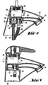
- Fig. 2 shows another type of on an enlarged scale Execution of a supply line through the floor 10.
- the floor 10 in turn has a passage 11, which as Stepped bore is formed, the part with an enlarged Diameter directed into the interior of the receiving space 3 is.
- the feed line 13 has a nipple 19 in the region of its end on.
- This nipple contains an outer diameter that the Corresponds to the inner diameter of the enlarged part of the passage 11.
- the nipple 19 has two circumferential grooves 20, a groove 20 of which comes to rest in the passage 11, while the second groove 20 is outside the bottom 10. Both Grooves are intended to receive one O-ring 21 each.
- the bottom 10 also has a circumferential surface in its outer surface 22 Groove 23 in which an O-ring is inserted. This O-ring seals against the valve body 1.
- valve system 4 which in its end surface depressions has, the inner diameter of the outer diameter of the Nipple 19 corresponds.
- the receiving space 3 is substantially cylindrical and from the mixing system 4 is completely filled, so that the mixing system 4 by the entire recording space is centered on the in Fig. 3 shown embodiment of the receiving space 3 differently designed.
- the receiving space 3 in the embodiment 3 and 4 again contains an upward Opening 25 through which the schematically shown mixing system 4 can be used.
- the centering is done by a screw-in cap 26 which with its screw-in end 28 Valve system 4 surrounds on all sides.
- the transverse wall 31 has an inside with a thread provided neck 32, into which a threaded rod 33 is screwed is. This is used to fasten the valve body.
- a floor 34 On the top of the transverse wall 31 there is a floor 34 which contains a passage 35. In the passage 35 is a supply hose 36 inserted from above, in the area of his End a nipple 37 similar to the nipple 19 of FIG. 2 having.
- the bottom 34 is constructed in two parts and contains a first disc-shaped part 38. This lies flat on the transverse wall 31 on. Via the upper valve system 4 facing Side 39 of the disk part 38 protrudes from the nipple 37. With the second part 40 is connected to the disk-shaped part 38, which surrounds the disk part 38 on all sides and opposite it is sealed. The second part 40 of the bottom 34 forms a kind of hood over the disc part 38, through which not only the water supply with the hose 36 he follows. Also the mixed water leaving the valve system 4 passes through an opening 41 in the valve system 4 facing End face of the second part 40 in this hood-like Part and from there behind the drawing plane into that Interior of the outlet line 42, which is integral to the upper Part 40 of the bottom 34 is formed. The outlet line 42 extends to the end of the outlet spout 43. There the Outlet line 42 an outlet mouthpiece 44 with a ventilation device on. This outlet mouthpiece 44 is direct screwed onto the outlet line 42.
- the transverse wall 31 of the valve body 1 contains an opening, to lie in the assembled state of the connecting hose comes.
- This opening 45 is to the outside, i.e. in Fig. 3 to the right, open. This enables the pre-assembled, bottom 34 provided with hose 36 to be inserted laterally into the receiving space 3.
- Fig. 4 shows an embodiment, that of the embodiment 3 is very similar, so that only the differences being represented.
- transverse wall 46 which is also parallel to the bearing surface 30 of the Fitting body runs.
- This transverse wall 46 has a central one Opening 47 so that around the opening 47 a circumferential Shoulder 48 is formed, on which the bottom 34 rests.
- the one in Fig. 4 must first Invisible lower end of the hose 36 and the second Not shown supply hose through the opening 47 and then the bottom 34 from the side in the recording room 3 are introduced.
- the attachment via the valve system 4 and the nut 26 in again the same way as in the embodiment Fig. 3.
Landscapes
- Engineering & Computer Science (AREA)
- General Engineering & Computer Science (AREA)
- Mechanical Engineering (AREA)
- Valve Housings (AREA)
- Multiple-Way Valves (AREA)
- Supports For Pipes And Cables (AREA)
- Domestic Plumbing Installations (AREA)
- Infusion, Injection, And Reservoir Apparatuses (AREA)
- Percussion Or Vibration Massage (AREA)
- Bidet-Like Cleaning Device And Other Flush Toilet Accessories (AREA)
Abstract
Description
Die Erfindung geht aus von einer Sanitärarmatur mit einem Armaturenkörper, in dem ein Aufnahmeraum zur Aufnahme eines Ventilsystems, insbesondere einer Mischkartusche, gebildet ist.The invention is based on a sanitary fitting with a Fitting body in which a receiving space for receiving a Valve system, in particular a mixing cartridge is.
Üblicherweise wird der Aufnahmeraum durch einen festen gegossenen Boden begrenzt, der in der Regel Teil des Armaturengrundkörpers ist. Durch diesen festen Boden werden die Rohre angeschraubt, angelötet oder eingesteckt. Auf dem Boden liegt ggf. unter Zwischenlage einer Adapterplatte das Ventilsystem auf.Usually the recording space is cast by a solid Bottom limited, which is usually part of the body of the valve is. Through this solid floor, the pipes screwed, soldered or plugged in. Lies on the floor if necessary with the interposition of an adapter plate the valve system on.
Es ist bereits eine Sanitärarmatur bekannt (DE-A1-35 13 840), bei der ein in den Armaturenkörper einsetzbarer Boden zur Anbringung von Zuleitungen und zur Anbringung einer Gewindestange dient. Mit dieser Gewindestange wird der Armaturenkörper an einer Unterlage festgespannt.A sanitary fitting is already known (DE-A1-35 13 840), in which a Fitting body insertable floor for attaching supply lines and for attaching a threaded rod is used. With this threaded rod, the valve body is attached to one Underlay clamped.
Weiterhin bekannt ist eine Sanitärarmatur, die einen fest in dem Armaturengrundkörper eingeschweißten Boden mit daran angeschweißten Ansätzen zur Anbringung von Zuleitungen aufweist (DE-A1-44 38 647).Also known is a sanitary fitting which is fixed in the base body of the fitting welded-in floor with attachments welded to it for attaching supply lines has (DE-A1-44 38 647).
Weiterhin bekannt sind Mischbatterien, bei denen der Boden einstückiger Teil des Grundkörpers ist (DE-A1-44 21 387, DE-A1-44 43 895, EP-A1-681 127).Mixer taps are also known, in which the bottom is an integral part of the Basic body is (DE-A1-44 21 387, DE-A1-44 43 895, EP-A1-681 127).
Der Erfindung liegt die Aufgabe zugrunde, eine Möglichkeit zu schaffen, den Armaturengrundkörper, der üblicherweise aus Guß besteht, zu vereinfachen.The invention has for its object a possibility create the valve body, which is usually made of cast iron is to simplify.
Zur Lösung dieser Aufgabe schlägt die Erfindung eine Sanitärarmatur mit den im Anspruch 1 genannten Merkmalen vor. Weiterbildungen der Erfindung sind Gegenstand von Unteransprüchen. To achieve this object, the invention proposes a sanitary fitting with the features mentioned in claim 1. further developments the invention are the subject of dependent claims.
Durch die getrennte Herstellung des Bodens, der eine sehr einfache geometrische Form aufweisen kann, vereinfacht sich die Herstellung. Der Armaturenkörper braucht zur Festlegung des Bodens nur kleine Vorsprünge aufzuweisen, so daß der Armaturenkörper ebenfalls einfacher herzustellen ist. Insbesondere ist es auch möglich, durch unterschiedliche Böden einen Armaturengrundkörper für unterschiedliche und in ihren Abmessungen verschiedene Ventilsysteme zu verwenden.Due to the separate production of the floor, which is a very can have simple geometric shape, simplified the production. The valve body needs to fix of the bottom to have only small projections, so that the valve body is also easier to manufacture. In particular it is also possible through different floors a valve body for different and in their Dimensions to use different valve systems.
Bei der Montage wird beispielsweise zunächst der Boden in den Armaturenkörper eingesetzt und anschließend das Ventilsystem, bei dem es sich um eine standardisierte Mischerkartusche handeln kann. Zur Festlegung des Bodens kann es ausreichen, wenn dieser an Anlagenoppen anliegt und durch das Festlegen der Mischerkartusche ebenfalls mit festgelegt wird.When installing, for example, the floor is first in the Fitting body and then the valve system, which is a standardized mixer cartridge can. It may be sufficient to fix the floor if this is applied to system knobs and by setting the Mixer cartridge is also specified.
Erfindungsgemäß kann in Weiterbildung vorgesehen sein, daß der Boden den Aufnahmeraum abschließt. Er kann beispielsweise an einzelnen oder durchgehenden schmalen Vorsprüngen anliegen.According to the invention it can be provided in a further development that the floor closes the recording room. For example, it can rest on individual or continuous narrow projections.
Es kann erfindungsgemäß ebenfalls vorgesehen sein, daß der Boden eine Auflagefläche für das Ventilsystem bildet, beispielsweise insbesondere für die erwähnte Endfläche des Ventilsystems, in dem die mindestens eine Wasserdurchtrittsöffnung ausmündet.It can also be provided according to the invention that the Bottom forms a support surface for the valve system, for example especially for the mentioned end face of the valve system, in which the at least one water passage opening opens.
Das Wasser gelangt beispielsweise von einer Zuleitung durch den Boden zu der Öffnung des Ventilsystems. Je nach Ausbildung des Ventilsystems kann auch das das Ventilsystem verlassende Wasser durch den Boden hindurchgeführt werden.For example, the water passes through a supply line the bottom to the opening of the valve system. Depending on the training of the valve system can also be the one leaving the valve system Water can be run through the floor.
Die Erfindung schlägt vor, daß an den mindestens einen Durchgang des Bodens eine Anschlußleitung anschließbar sein kann. Es ist beispielsweise denkbar, daß der Boden einen Nippel zum Anschluß einer Anschlußleitung, beispielsweise einen Schraubanschluß aufweist. In diesem Fall kann der Durchgang des Bodens direkt mit der Wasseraustrittsöffnung des Ventilsystems in Verbindung stehen.The invention proposes that at least one pass the bottom of a connecting line can be connected. It is conceivable, for example, that the bottom has a nipple for Connection of a connecting line, for example a screw connection having. In this case, the passage of the floor directly with the water outlet opening of the valve system stay in contact.
Die Erfindung schlägt vor, daß in den Durchgang des Bodens eine mit einem Nippel versehene Anschlußleitung einsetzbar ist. Dann geschieht die Wasserführung von der mit dem Nippel versehenen Anschlußleitung direkt zu dem Ventilsystem, wobei eine Abdichtung zwischen dem Nippel und dem Ventilsystem vorgesehen wird.The invention proposes that in the passage of the floor a connecting line provided with a nipple can be used is. Then the water flows from the nipple provided connecting line directly to the valve system, wherein a seal between the nipple and the valve system is provided becomes.
Erfindungsgemäß kann vorgesehen sein, daß der Nippel über die dem Ventilsystem zugewandte Fläche des Bodens vorspringt und in eine Öffnung des Ventilsystems eingreift. Auch hier kann eine Abdichtung zwischen dem Nippel und dem Ventilsystem vorgesehen sein,According to the invention it can be provided that the nipple over the projecting surface of the floor facing the valve system and engages in an opening of the valve system. Here too a seal between the nipple and the valve system is provided his,
Insbesondere kann vorgesehen sein, daß der vorspringende Nippel eine Ausrichtung des Ventils bewirkt.In particular, it can be provided that the projecting nipple alignment of the valve.
Es ist ebenfalls denkbar, daß das Ventilsystem einen Vorsprung aufweist, der nippelartig in den Durchgang oder eine den Durchgang umgebende Vertiefung des Bodens eingreift.It is also conceivable that the valve system has a projection has the nipple-like in the passage or a engages the recess surrounding the passage of the floor.
Der Nippel kann am Ende einer Rohrleitung angeordnet sein, also beispielsweise einem Kupferrohr, das üblicherweise zum Anschluß von Sanitärarmaturen dient.The nipple can be arranged at the end of a pipeline, So for example a copper tube that is usually used for Connection of sanitary fittings is used.
Ebenfalls kann vorgesehen sein, daß der Nippel am Ende eines Zuleitungsschlauches angeordnet ist. Dies ist insbesondere bei komplizierteren Formen sinnvoll, da dann der Schlauch von der Seite der Armatur durch die Öffnung des Elementes, an dem die Sanitärarmatur befestigt werden soll, eingesteckt und eingefädelt werden kann. It can also be provided that the nipple at the end of a Supply hose is arranged. This is particularly so makes sense for more complicated shapes, because then the hose from the side of the valve through the opening of the element on which the sanitary fitting is to be attached, inserted and can be threaded.
Diese Lösung ist insbesondere dann von Vorteil, wenn, wie die Erfindung weiterhin vorschlägt, der Boden durch die gleiche Öffnung in den Aufnahmeraum des Armaturenkörpers einsetzbar ist, durch den auch das Ventilsystem eingesetzt wird.This solution is particularly advantageous if, as the invention continues proposes the floor through the same opening in the receiving space of the valve body through which the valve system is also used.
Es ist jedoch ebenfalls möglich und wird von der Erfindung in Weiterbildung vorgeschlagen, dass der Boden seitlich in den Aufnahmeraum, in dem er angeordnet sein soll, einschiebbar ist.However, it is also possible and is proposed by the invention in a further development, that the floor laterally in the recording space in which it will be arranged should be insertable.
Erfindungsgemäß kann vorgesehen sein, dass der Boden eine Durchführung für das das Mischsystem verlassende Mischwasser aufweist. Diese Durchführung kann entweder den Boden in einer ähnlichen Richtung durchqueren wie die Zuleitung, d. h. von der einen Stirnfläche zu der anderen Stirnfläche. Es ist aber ebenfalls möglich, dass die Durchführung für das Mischwasser den Boden seitlich verlässt, also bei einem zylindrischen Aufnahmeraum in der Mantelfläche des Bodens.According to the invention it can be provided that the floor is a passage for the has mixed water leaving the mixing system. This can be done either cross the floor in a direction similar to the feed line, d. H. from one end face to the other end face. But it is also possible that the feed-through for the mixed water leaves the ground on the side, i.e. with one cylindrical receiving space in the lateral surface of the floor.
Der Boden kann in seiner einfachsten Ausführung etwa scheibenförmig mit ebenen Begrenzungsflächen ausgebildet sein.In its simplest version, the floor can be approximately disc-shaped with flat surfaces Boundary surfaces can be formed.
Es ist aber ebenfalls möglich, den Boden aus zwei oder mehr miteinander verbindbaren Teilen aufzubauen. Dies kann fertigungstechnische Vorteile haben. Auch in diesem Fall ist der boden ein getrenntes, fabrikmäßig herstellbares und zusammensetzbares Bauteil der Sanitärarmatur.But it is also possible to connect the floor from two or more together Build up parts. This can have manufacturing advantages. Also in this In this case, the floor is a separate, factory-made and assembled Component of the sanitary fitting.
Erfindungsgemäß ist vorgesehen, dass die zu einem Auslauf der Armatur führende Auslaufleitung einstückig mit dem Boden bzw. mit einem der mehreren Teile des Bodens ausgebildet ist. According to the invention, it is provided that the valve leads to an outlet Outlet line in one piece with the bottom or with one of the several parts of the Soil is formed.
Die Erfindung schlägt vor, die Zuleitungen und den Boden sowie ggf. auch die Auslaufleitungen vorkonfektioniert herzustellen.The invention proposes the supply lines and the floor and possibly also the outlet lines Manufacture pre-assembled.
In Weiterbildung der Erfindung kann vorgesehen sein, dass das Ventilsystem an dem Boden fixiert ist, der seinerseits an dem Armaturengrundkörper fixierbar ist.In a development of the invention it can be provided that the valve system on the Floor is fixed, which in turn can be fixed to the base body of the fitting.
Um die durch die einfachere Herstellung des Armaturenkörpers verringerten Kosten nochmals weiter zu verringern, kann erfindungsgemäß vorgesehen sein, den Boden aus Kunststoff herzustellen.In order to reduce costs due to the simpler manufacture of the valve body To further reduce the floor can be provided according to the invention made of plastic.
Weitere Merkmale, Einzelheiten und Vorzüge ergeben sich aus den Patentansprüchen, deren Wortlaut durch Bezugnahme zum Inhalt der Beschreibung gemacht wird, der folgenden Beschreibung einer bevorzugten Ausführungsform der Erfindung sowie anhand der Zeichnung. Hierbei zeigen:
- Fig. 1
- einen Teilschnitt durch eine Sanitärarmatur;
- Fig. 2
- in vergrößertem Maßstab eine teilweise geschnittene Seitenansicht des Bodens mit einer mit einem Nippel versehenen Anschlussleitung;
- Fig. 3
- einen Schnitt durch eine weitere Sanitärarmatur nach der Erfindung;
- Fig. 4
- einen Schnitt durch eine nochmals weitere Ausführungsform einer Sanitärarmatur.
- Fig. 1
- a partial section through a sanitary fitting;
- Fig. 2
- on an enlarged scale, a partially sectioned side view of the bottom with a connecting line provided with a nipple;
- Fig. 3
- a section through a further sanitary fitting according to the invention;
- Fig. 4
- a section through yet another embodiment of a sanitary fitting.
Die Figuren 1 und 2 zeigen nicht die Erfindung, dienen aber zum besseren Verständnis.
Fig. 1 zeigt vereinfacht eine Sanitärarmatur in ihren wesentlichen Teilen. Die Sanitärarmatur
enthält einen Armaturengrundkörper 1, der im dargestellten Beispiel etwa
zylindrisch
ausgebildet ist und an seiner in Fig. 1 rechten Zylindermantelfläche
einen Auslauf 2 bildet. Am nicht dargestellten Ende
des Auslaufs 2 ist eine Auslauföffnung angeordnet, aus der
das die Armatur verlassende Wasser austritt.Figures 1 and 2 do not show the invention, but serve for better understanding.
Fig. 1 shows simplified a sanitary fitting in its essential parts. The sanitary fitting contains a fitting base body 1, which is approximately cylindrical in the example shown and forms an
Der Armaturenkörper 1 ist innen hohl und weist einen ebenfalls
zylindrischen Aufnahmeraum 3 auf, der in der dargestellten
Ausführungsform im wesentlichen vollständig von
einem Ventilsystem 4 ausgefüllt ist. Im Bereich seines äußeren
Endes ist der Aufnahmeraum 3 des Armaturenkörpers 1 mit
einem Innengewinde 5 versehen, in das eine Kappe 6 eingeschraubt
ist. Die Kappe 6 legt das Mischsystem 5 in dem Armaturenkörper
1 fest. Zur Betätigung des Mischsystems weist
dieses einen Schaft 7 auf, an dem ein Betätigungsgriff angebracht
werden kann. Durch Betätigen des Betätigungsgriffs,
nämlich einerseits durch eine Verschwenkung und andererseits
durch eine Verdrehung, kann das Ventilsystem betätigt werden.The valve body 1 is hollow on the inside and also has one
An dem Ende des Aufnahmeraumes 3 weist der Armaturenkörper 1
eine umlaufende, nur geringfügig nach innen vorspringende
Rippe 8 auf. Anstelle einer umlaufenden Rippe 8 könnten auch
einzelne Vorsprünge vorhanden sein. Die Rippe 8 bildet eine
umlaufende, in einer Ebene liegende Schulter 9. Die Schulter
9 ist zu dem durch die Kappe 6 verschließbaren äußeren Ende
des Aufnahmeraumes 3 gerichtet.At the end of the receiving
Auf die Schulter 9 ist ein Boden 10 aufgelegt, dessen Außenumfang
dem Innenumfang des Aufnahmeraumes 3 entspricht. Er
füllt daher den Aufnahmeraum 3 im wesentlichen vollständig
aus und wird auf diese Weise in Querrichtung festgelegt.A
Der Boden 10 weist zwei Durchgänge 11 auf, die auf der in
Fig. 1 unteren Seite 12 des Bodens 10, d.h. auf der dem Ventilsystem
4 abgewandten Seite des Bodens 10, mit je einer
Zuleitung 13 verbunden sind. Bei den Zuleitungen 13 kann es
sich beispielsweise um Kupferrohre handeln, die in die Öffnungen
des Bodens 10 bis zur Anlage an der Verengung 14 eingeschoben
und mit dem Boden 10 verlötet sind.The
Auf der dem Ventilsystem 14 zugewandten oberen Seite 15 des
Bodens sind die Durchgänge 11 ringsum verbreitert. In diese
verbreiterten Teile der Öffnungen greifen vorspringende zylindrische
Ansätze 16 des Ventilsystems 4 ein. Die gegenüber
der Endfläche des Ventilsystems 4 vorspringenden Ansätze 16
liegen auf den oberen Seiten der Verengung 13 auf. Dadurch
bildet der Boden 10 auch eine Anlagefläche für das Ventilsystem
4. Die Festlegung in axialer Richtung erfolgt durch das
Einschrauben der Kappe 6. Rings um die Vorsprünge 16 sind in
der Endfläche des Ventilsystems 14 Ringnuten angeordnet, in
denen je ein O-Ring 27 eingesetzt ist.On the
Die dem Boden 10 zugewandte Seite des Ventilsystems 4 enthält
eine weitere Öffnung 17, die durch einen querverlaufenden Kanal
mit einer seitlichen Öffnung 18 des Aufnahmeraumes in
Verbindung steht, so daß das das Ventilsystem 4 verlassende
Mischwasser über die Öffnungen 17 und 18 in den Auslauf 2 gelangen
kann.The side of the valve system 4 facing the
Das Zusammensetzen der Sanitärarmatur nach Fig. 1 geschieht
derart, daß in den gegossenen Armaturenkörper 1 zunächst von
oben, d.h. aus Richtung des Innengewindes 5, der mit den Zuleitungen
13 versehen Boden 10 eingesetzt wird, bis er auf
der Schulter 9 zur Anlage gelangt. Anschließend wird das Ventilsystem
4 aus der gleichen Richtung eingesetzt, bis seine
Ansätze 16 in die verbreiterten Durchgänge 11 eingreifen. Anschließend
wird die Kappe 6 aufgesetzt und in das Innengewinde
5 eingeschraubt.The assembly of the sanitary fitting according to Fig. 1 happens
such that in the cast fitting body 1 first of
above, i.e. from the direction of the
Fig. 2 zeigt in vergrößertem Maßstab eine andere Art der
Durchführung einer Zuleitung durch den Boden 10. Fig. 2 shows another type of on an enlarged scale
Execution of a supply line through the
Der Boden 10 weist wiederum einen Durchgang 11 auf, der als
Stufenbohrung ausgebildet ist, wobei der Teil mit vergrößertem
Durchmesser in das Innere des Aufnahmeraumes 3 gerichtet
ist.The
Die Zuleitung 13 weist im Bereich ihres Endes einen Nippel 19
auf. Dieser Nippel enthält einen Außendurchmesser, der dem
Innendurchmesser des erweiterten Teils des Durchgangs 11 entspricht.
Der Nippel 19 weist zwei umlaufende Nuten 20 auf,
von denen eine Nut 20 in dem Durchgang 11 zu liegen kommt,
während die zweite Nut 20 außerhalb des Bodens 10 liegt. Beide
Nuten sind zur Aufnahme je eines O-Ringes 21 bestimmt.The
Auch der Boden 10 weist in seiner Mantelfläche 22 eine umlaufende
Nut 23 auf, in die ein O-Ring eingesetzt wird. Dieser
O-Ring übernimmt die Abdichtung gegenüber dem Armaturenkörper
1.The bottom 10 also has a circumferential surface in its
Der Anschluß nach Fig. 2 ist dazu bestimmt, mit einem Ventilsystem
4 zusammenzuwirken, das in seiner Endfläche Vertiefungen
aufweist, deren Innendurchmesser dem Außendurchmesser des
Nippels 19 entspricht. Auch hier kann eine Ausrichtung zwischen
dem Ventilsystem 4, dem Aramturenkörper 1 und dem Boden
10 durch dieses Eingreifen der Nippel 19 bewirkt werden.2 is intended to be used with a valve system
4 interact, which in its end surface depressions
has, the inner diameter of the outer diameter of the
Während bei der Ausführungsform nach Fig. 1 der Aufnahmeraum
3 im wesentlichen zylinderförmig ist und von dem Mischsystem
4 vollständig ausgefüllt wird, so daß das Mischsystem 4 durch
den Aufnahmeraum insgesamt zentriert wird, ist bei der in
Fig. 3 dargestellten Ausführungsform der Aufnahmeraum 3 anders
gestaltet. Der Aufnahmeraum 3 bei der Ausführungsform
nach Fig. 3 und 4 enthält wiederum eine nach oben gerichtete
Öffnung 25, durch die das schematisch dargestellte Mischsystem
4 eingesetzt werden kann. Die Zentrierung erfolgt durch
eine Einschraubkappe 26, die mit ihrem Einschraubende 28 das
Ventilsystem 4 allseits umgibt. While in the embodiment of FIG. 1, the receiving
Von dem Aufnahmeraum 3 bleibt nur eine an dem Armaturenkörper
angeformte Wand 29 übrig. Diese geht in eine Querwand 31
über, die parallel zur Auflagefläche 30 des Körpers 1 verläuft.
Die Querwand 31 weist einen innen mit einem Gewinde
versehenen Ansatz 32 auf, in den eine Gewindestange 33 eingeschraubt
ist. Diese dient zur Befestigung des Armaturenkörpers.Only one of the receiving
Auf der Oberseite der Querwand 31 liegt ein Boden 34 auf, der
einen Durchgang 35 enthält. In den Durchgang 35 ist ein Zuleitungsschlauch
36 von oben eingesteckt, der im Bereich seines
Endes einen dem Nippel 19 der Fig. 2 ähnlichen Nippel 37
aufweist.On the top of the
Der Boden 34 ist zweiteilig aufgebaut und enthält ein erstes
scheibenförmiges Teil 38. Dieses liegt flächig auf der Querwand
31 auf. Über die dem Ventilsystem 4 zugewandte obere
Seite 39 des Scheibenteils 38 ragt der Nippel 37 hinaus. Mit
dem scheibenförmigen Teil 38 ist der zweite Teil 40 verbunden,
der den Scheibenteil 38 allseits umgibt und diesem gegenüber
abgedichtet ist. Der zweite Teil 40 des Bodens 34
bildet über dem Scheibenteil 38 eine Art Haube, durch die
nicht nur die Wasserzuleitung mit Hilfe des Schlauches 36
erfolgt. Auch das das Ventilsystem 4 verlassende Mischwasser
gelangt durch eine Öffnung 41 in der dem Ventilsystem 4 zugewandten
Endfläche des zweiten Teils 40 in diesen haubenartigen
Teil und von dort aus hinter der Zeichnungsebene in das
Innere der Auslaufleitung 42, die einstückig an dem oberen
Teil 40 des Bodens 34 angeformt ist. Die Auslaufleitung 42
reicht bis zum Ende der Auslaufschnauze 43. Dort weist die
Auslaufleitung 42 ein Auslaufmundstück 44 mit einer Belüftungseinrichtung
auf. Dieses Auslaufmundstück 44 ist direkt
auf die Auslaufleitung 42 aufgeschraubt. The bottom 34 is constructed in two parts and contains a first
disc-shaped
Bei der Ausführungsform der Fig. 3 wird der Boden 34 mit dem
vorher eingesetzten Zuleitungsschlauch 36 seitlich in den
Aufnahmeraum 3 eingesetzt. Er bildet auch in diesem Fall eine
Auflagefläche für das Ventilsystem 4.In the embodiment of Fig. 3, the bottom 34 with the
previously used
Die Querwand 31 des Armaturenkörpers 1 enthält eine Öffnung,
in der in montiertem Zustand der Anschlußschlauch zu liegen
kommt. Diese Öffnung 45 ist zur Außenseite hin, d.h. in
Fig. 3 nach rechts, offen. Dadurch ist es möglich, den vorkonfektionierten,
mit dem Schlauch 36 versehenen Boden 34
seitlich in den Aufnahmeraum 3 einzuschieben.The
Fig. 4 zeigt eine Ausführungsform, die der Ausführungsform
nach Fig. 3 sehr ähnlich ist, so daß nur noch die Unterschiede
dargestellt werden.Fig. 4 shows an embodiment, that of the
Bei der Ausführungsform nach Fig. 4 ist eine Querwand 46 vorhanden,
die ebenfalls parallel zu der Auflagefläche 30 des
Armaturenkörpers verläuft. Diese Querwand 46 weist eine zentrale
Öffnung 47 auf, so daß um die Öffnung 47 eine umlaufende
Schulter 48 gebildet ist, auf der der Boden 34 aufliegt.
Zum Einsetzen des Bodens muß zunächst das in Fig. 4
nicht zu sehende untere Ende des Schlauches 36 und des zweiten
nicht dargestellten Zuleitungsschlauches durch die Öffnung
47 gesteckt und dann der Boden 34 von der Seite her in
den Aufnahmeraum 3 eingeführt werden. Sobald der Schlauch 36
durch die Öffnung 47 hindurch geführt ist und der Boden 34
auf der umlaufenden Schulter 48 aufliegt, kann die Befestigung
über das Ventilsystem 4 und die Mutter 26 wieder in
gleicher Weise erfolgen wie bei der Ausführungsform nach
Fig. 3.In the embodiment according to FIG. 4 there is a
Claims (16)
- Sanitary fitting with1.1 a fitting body (1),1.2 a reception space (3) constructed therein for receiving a valve system (4),1.3 a valve system (4) insertable into the reception space (3) and which1.3.1 has in the vicinity of its inner end face at least one water passage opening, as well as with1.4 a base (10, 34) associated with the inner end face of the valve system (4) and which1.4.1 has at least one passage (11, 35) associated with the water passage opening of the valve system (5),1.4.2 is constructed as a separate component and1.4.3 is insertable in the reception space (3), as well as with1.5 an outflow pipe (42) leading to an outflow (43) of the fitting, characterized in that1.6 the outflow pipe (42) is constructed in one piece with the base (34) or a part (40) of the base (34).
- Sanitary fitting according to claim 1, wherein the base (10, 34) terminates the reception space (3).
- Sanitary fitting according to claim 1 or 2, wherein the base (10, 34) forms a bearing surface for the valve system (4) and in particular for its end face.
- Sanitary fitting according to one of the preceding claims, wherein a connecting pipe can be connected to the at least one passage (11, 35) of the base (10, 34).
- Sanitary fitting according to one of the preceding claims, wherein a connecting pipe (13, 36) provided with a nipple (19, 37) is insertable in the passage (11, 35) of the base (10, 34).
- Sanitary fitting according to claim 5, wherein the nipple (19) projects over the face (15) of the base (10) facing the valve system (4) and optionally engages in an opening of the valve system (4).
- Sanitary fitting according to claim 5 or 6, wherein the nipple (19) brings about an orientation of the valve system (4).
- Sanitary fitting according to one of the claims 5 to 7, wherein the nipple (19, 37) forms the end of a pipeline (13).
- Sanitary fitting according to one of the claims 5 to 7, wherein the nipple (37) forms the end of a hose (36).
- Sanitary fitting according to one of the preceding claims, wherein the base (10) can be inserted through the same opening into the reception space (3) of the fitting body (1) as the valve system (4).
- Sanitary fitting according to one of the claims 1 to 9, wherein the base (34) is insertable and in particular can be slid laterally into the reception space (3) of the fitting body (1).
- Sanitary fitting according to one of the preceding claims, wherein the base (34) has a passage for the mixed water leaving the valve system (4).
- Sanitary fitting according to one of the preceding claims, wherein the base (34) is constructed from two parts (38, 40).
- Sanitary fitting according to one of the preceding claims, wherein the supply pipes (13, 36) and the base (10, 34) are prefabricated.
- Sanitary fitting according to one of the preceding claims, wherein the valve system (4) can be fixed to the base (10, 34).
- Sanitary fitting according to one of the preceding claims, wherein the base (10, 34) is made from plastic.
Applications Claiming Priority (2)
| Application Number | Priority Date | Filing Date | Title |
|---|---|---|---|
| DE19620283A DE19620283A1 (en) | 1996-05-21 | 1996-05-21 | Sanitary fitting |
| DE19620283 | 1996-05-21 |
Publications (3)
| Publication Number | Publication Date |
|---|---|
| EP0809056A2 EP0809056A2 (en) | 1997-11-26 |
| EP0809056A3 EP0809056A3 (en) | 1998-05-13 |
| EP0809056B1 true EP0809056B1 (en) | 2003-07-23 |
Family
ID=7794805
Family Applications (1)
| Application Number | Title | Priority Date | Filing Date |
|---|---|---|---|
| EP97108246A Expired - Lifetime EP0809056B1 (en) | 1996-05-21 | 1997-05-21 | Sanitary fitting |
Country Status (5)
| Country | Link |
|---|---|
| EP (1) | EP0809056B1 (en) |
| AT (1) | ATE245781T1 (en) |
| DE (2) | DE19620283A1 (en) |
| DK (1) | DK0809056T3 (en) |
| ES (1) | ES2202521T3 (en) |
Families Citing this family (1)
| Publication number | Priority date | Publication date | Assignee | Title |
|---|---|---|---|---|
| DE19913214A1 (en) * | 1999-03-24 | 2000-09-28 | Grohe Armaturen Friedrich | Valve cartridge arrangement |
Family Cites Families (13)
| Publication number | Priority date | Publication date | Assignee | Title |
|---|---|---|---|---|
| DE2330927C2 (en) * | 1973-06-18 | 1983-11-10 | Ideal-Standard Gmbh, 5300 Bonn | Sanitary water valve made of plastic |
| DE3119313C2 (en) * | 1981-05-15 | 1985-10-03 | Hansa Metallwerke Ag, 7000 Stuttgart | Plumbing fixture |
| US4649958A (en) * | 1982-06-28 | 1987-03-17 | Masco Corporation Of Indiana | Faucet and spout construction |
| DE3509520A1 (en) * | 1985-03-16 | 1986-09-18 | Hansa Metallwerke Ag, 7000 Stuttgart | Sanitary fitting |
| DE3513840A1 (en) * | 1985-04-17 | 1986-10-30 | TA Rokal GmbH, 4054 Nettetal | Sanitary fitting |
| CH673689A5 (en) * | 1986-08-22 | 1990-03-30 | Wallisellen Ag Armaturen | |
| FR2641052B1 (en) * | 1988-12-23 | 1991-03-29 | Presto Robinets Sa | |
| DE9116532U1 (en) * | 1991-07-27 | 1993-02-18 | Wilhelm Keller Gmbh & Co Kg, 72147 Nehren | Single lever mixer |
| DE4313439A1 (en) * | 1993-04-23 | 1994-10-27 | Ideal Standard | Sanitary water valve |
| DE4415797A1 (en) * | 1994-05-05 | 1995-11-09 | Grohe Armaturen Friedrich | Water tap |
| DE4421387B4 (en) * | 1994-06-18 | 2005-04-07 | Grohe Water Technology Ag & Co. Kg | pillar mixer |
| DE4438647A1 (en) * | 1994-10-28 | 1996-05-02 | Grohe Kg Hans | Sanitary ware fitting for mixing valve |
| DE4443895A1 (en) * | 1994-12-09 | 1996-06-13 | Grohe Kg Hans | Sanitary fitting |
-
1996
- 1996-05-21 DE DE19620283A patent/DE19620283A1/en not_active Withdrawn
-
1997
- 1997-05-21 AT AT97108246T patent/ATE245781T1/en not_active IP Right Cessation
- 1997-05-21 DE DE59710452T patent/DE59710452D1/en not_active Expired - Fee Related
- 1997-05-21 DK DK97108246T patent/DK0809056T3/en active
- 1997-05-21 EP EP97108246A patent/EP0809056B1/en not_active Expired - Lifetime
- 1997-05-21 ES ES97108246T patent/ES2202521T3/en not_active Expired - Lifetime
Also Published As
| Publication number | Publication date |
|---|---|
| DE59710452D1 (en) | 2003-08-28 |
| EP0809056A3 (en) | 1998-05-13 |
| ATE245781T1 (en) | 2003-08-15 |
| ES2202521T3 (en) | 2004-04-01 |
| DK0809056T3 (en) | 2003-11-17 |
| EP0809056A2 (en) | 1997-11-26 |
| DE19620283A1 (en) | 1997-11-27 |
Similar Documents
| Publication | Publication Date | Title |
|---|---|---|
| EP1261824B1 (en) | Sanitary appliance | |
| DE3510732A1 (en) | METHOD FOR PRODUCING TAPS AND SPOUTS, TAPPING INSERTS, AND TAPS AND SPOUTS PRODUCED BY THE METHOD | |
| DE2328361A1 (en) | MIXING TAP, IN PARTICULAR TAP FOR WARM AND COLD WATER | |
| DE2527132A1 (en) | Hot water radiator valve connection - twin type radiator panels are linked with double sealed valve | |
| WO2015117768A1 (en) | Fixture having a pivoting outlet | |
| DE3838205C2 (en) | ||
| EP0809056B1 (en) | Sanitary fitting | |
| DE3133267C2 (en) | Water outlet fitting, especially for sanitary purposes | |
| EP0309397A1 (en) | Water supply connection arrangement for sanitary installations | |
| EP0790448B2 (en) | Sanitary fitting | |
| DE19500950A1 (en) | Fitting for making and interrupting fluid connections on branch pipes | |
| DE19623004A1 (en) | Valve tapping fitting for plastic supply lines, preferably under media pressure | |
| EP0716255B1 (en) | Sanitary valve | |
| DE19911066A1 (en) | Sanitary fitting and assembly process | |
| DE3116502A1 (en) | Set of structural elements for converting two-handle flush-mounted fittings | |
| DE3332773A1 (en) | Sanitary fitting | |
| DE9309418U1 (en) | Lever mixer tap | |
| EP0780523B1 (en) | Mixing valve with inclined mounted supply conduit | |
| EP0855635B1 (en) | Sanitary fittings | |
| DE2012827B2 (en) | Valve attachment | |
| DE19501313A1 (en) | Side shower with connecting nipple | |
| DE3525612C2 (en) | Pneumatic or hydraulic work or control element, e.g. Working cylinder or valve | |
| DE19509530A1 (en) | Sanitary thermostatic water mixing valve | |
| DE4215442A1 (en) | Mixer tap for wall connection - has connection nipples with rubber sealing ring and metal ring, to press it against casing tube | |
| DE3631001C2 (en) |
Legal Events
| Date | Code | Title | Description |
|---|---|---|---|
| PUAI | Public reference made under article 153(3) epc to a published international application that has entered the european phase |
Free format text: ORIGINAL CODE: 0009012 |
|
| AK | Designated contracting states |
Kind code of ref document: A2 Designated state(s): AT CH DE DK ES FI FR GB IT LI NL SE |
|
| RBV | Designated contracting states (corrected) |
Designated state(s): AT CH DE DK ES FI FR GB IT LI NL SE |
|
| PUAL | Search report despatched |
Free format text: ORIGINAL CODE: 0009013 |
|
| AK | Designated contracting states |
Kind code of ref document: A3 Designated state(s): AT CH DE DK ES FI FR GB IT LI NL SE |
|
| 17P | Request for examination filed |
Effective date: 19981021 |
|
| 17Q | First examination report despatched |
Effective date: 20010117 |
|
| GRAH | Despatch of communication of intention to grant a patent |
Free format text: ORIGINAL CODE: EPIDOS IGRA |
|
| GRAH | Despatch of communication of intention to grant a patent |
Free format text: ORIGINAL CODE: EPIDOS IGRA |
|
| RAP1 | Party data changed (applicant data changed or rights of an application transferred) |
Owner name: HANSGROHE AG |
|
| GRAA | (expected) grant |
Free format text: ORIGINAL CODE: 0009210 |
|
| AK | Designated contracting states |
Designated state(s): AT CH DE DK ES FI FR GB IT LI NL SE |
|
| PG25 | Lapsed in a contracting state [announced via postgrant information from national office to epo] |
Ref country code: NL Free format text: LAPSE BECAUSE OF FAILURE TO SUBMIT A TRANSLATION OF THE DESCRIPTION OR TO PAY THE FEE WITHIN THE PRESCRIBED TIME-LIMIT Effective date: 20030723 Ref country code: FI Free format text: LAPSE BECAUSE OF FAILURE TO SUBMIT A TRANSLATION OF THE DESCRIPTION OR TO PAY THE FEE WITHIN THE PRESCRIBED TIME-LIMIT Effective date: 20030723 |
|
| REG | Reference to a national code |
Ref country code: GB Ref legal event code: FG4D Free format text: NOT ENGLISH |
|
| REG | Reference to a national code |
Ref country code: CH Ref legal event code: EP |
|
| GBT | Gb: translation of ep patent filed (gb section 77(6)(a)/1977) |
Effective date: 20030723 |
|
| REG | Reference to a national code |
Ref country code: CH Ref legal event code: NV Representative=s name: SULZER MANAGEMENT AG |
|
| REF | Corresponds to: |
Ref document number: 59710452 Country of ref document: DE Date of ref document: 20030828 Kind code of ref document: P |
|
| PG25 | Lapsed in a contracting state [announced via postgrant information from national office to epo] |
Ref country code: SE Free format text: LAPSE BECAUSE OF FAILURE TO SUBMIT A TRANSLATION OF THE DESCRIPTION OR TO PAY THE FEE WITHIN THE PRESCRIBED TIME-LIMIT Effective date: 20031023 |
|
| REG | Reference to a national code |
Ref country code: DK Ref legal event code: T3 |
|
| NLV1 | Nl: lapsed or annulled due to failure to fulfill the requirements of art. 29p and 29m of the patents act | ||
| REG | Reference to a national code |
Ref country code: ES Ref legal event code: FG2A Ref document number: 2202521 Country of ref document: ES Kind code of ref document: T3 |
|
| ET | Fr: translation filed | ||
| PG25 | Lapsed in a contracting state [announced via postgrant information from national office to epo] |
Ref country code: GB Free format text: LAPSE BECAUSE OF NON-PAYMENT OF DUE FEES Effective date: 20040521 Ref country code: AT Free format text: LAPSE BECAUSE OF NON-PAYMENT OF DUE FEES Effective date: 20040521 |
|
| PG25 | Lapsed in a contracting state [announced via postgrant information from national office to epo] |
Ref country code: ES Free format text: LAPSE BECAUSE OF NON-PAYMENT OF DUE FEES Effective date: 20040522 |
|
| PLBE | No opposition filed within time limit |
Free format text: ORIGINAL CODE: 0009261 |
|
| STAA | Information on the status of an ep patent application or granted ep patent |
Free format text: STATUS: NO OPPOSITION FILED WITHIN TIME LIMIT |
|
| PG25 | Lapsed in a contracting state [announced via postgrant information from national office to epo] |
Ref country code: LI Free format text: LAPSE BECAUSE OF NON-PAYMENT OF DUE FEES Effective date: 20040531 Ref country code: CH Free format text: LAPSE BECAUSE OF NON-PAYMENT OF DUE FEES Effective date: 20040531 |
|
| PG25 | Lapsed in a contracting state [announced via postgrant information from national office to epo] |
Ref country code: DK Free format text: LAPSE BECAUSE OF NON-PAYMENT OF DUE FEES Effective date: 20040601 |
|
| 26N | No opposition filed |
Effective date: 20040426 |
|
| PG25 | Lapsed in a contracting state [announced via postgrant information from national office to epo] |
Ref country code: DE Free format text: LAPSE BECAUSE OF NON-PAYMENT OF DUE FEES Effective date: 20041201 |
|
| REG | Reference to a national code |
Ref country code: DK Ref legal event code: EBP |
|
| GBPC | Gb: european patent ceased through non-payment of renewal fee |
Effective date: 20040521 |
|
| REG | Reference to a national code |
Ref country code: CH Ref legal event code: PL |
|
| PG25 | Lapsed in a contracting state [announced via postgrant information from national office to epo] |
Ref country code: FR Free format text: LAPSE BECAUSE OF NON-PAYMENT OF DUE FEES Effective date: 20050131 |
|
| REG | Reference to a national code |
Ref country code: FR Ref legal event code: ST |
|
| PG25 | Lapsed in a contracting state [announced via postgrant information from national office to epo] |
Ref country code: IT Free format text: LAPSE BECAUSE OF NON-PAYMENT OF DUE FEES;WARNING: LAPSES OF ITALIAN PATENTS WITH EFFECTIVE DATE BEFORE 2007 MAY HAVE OCCURRED AT ANY TIME BEFORE 2007. THE CORRECT EFFECTIVE DATE MAY BE DIFFERENT FROM THE ONE RECORDED. Effective date: 20050521 |
|
| REG | Reference to a national code |
Ref country code: ES Ref legal event code: FD2A Effective date: 20040522 |