EP0790448B2 - Sanitary fitting - Google Patents
Sanitary fitting Download PDFInfo
- Publication number
- EP0790448B2 EP0790448B2 EP97101770A EP97101770A EP0790448B2 EP 0790448 B2 EP0790448 B2 EP 0790448B2 EP 97101770 A EP97101770 A EP 97101770A EP 97101770 A EP97101770 A EP 97101770A EP 0790448 B2 EP0790448 B2 EP 0790448B2
- Authority
- EP
- European Patent Office
- Prior art keywords
- basic part
- fitting body
- fitting
- sanitary fitting
- sanitary
- Prior art date
- Legal status (The legal status is an assumption and is not a legal conclusion. Google has not performed a legal analysis and makes no representation as to the accuracy of the status listed.)
- Expired - Lifetime
Links
Images


Classifications
-
- E—FIXED CONSTRUCTIONS
- E03—WATER SUPPLY; SEWERAGE
- E03C—DOMESTIC PLUMBING INSTALLATIONS FOR FRESH WATER OR WASTE WATER; SINKS
- E03C1/00—Domestic plumbing installations for fresh water or waste water; Sinks
- E03C1/02—Plumbing installations for fresh water
- E03C1/021—Devices for positioning or connecting of water supply lines
-
- F—MECHANICAL ENGINEERING; LIGHTING; HEATING; WEAPONS; BLASTING
- F16—ENGINEERING ELEMENTS AND UNITS; GENERAL MEASURES FOR PRODUCING AND MAINTAINING EFFECTIVE FUNCTIONING OF MACHINES OR INSTALLATIONS; THERMAL INSULATION IN GENERAL
- F16K—VALVES; TAPS; COCKS; ACTUATING-FLOATS; DEVICES FOR VENTING OR AERATING
- F16K19/00—Arrangements of valves and flow lines specially adapted for mixing fluids
- F16K19/006—Specially adapted for faucets
-
- F—MECHANICAL ENGINEERING; LIGHTING; HEATING; WEAPONS; BLASTING
- F16—ENGINEERING ELEMENTS AND UNITS; GENERAL MEASURES FOR PRODUCING AND MAINTAINING EFFECTIVE FUNCTIONING OF MACHINES OR INSTALLATIONS; THERMAL INSULATION IN GENERAL
- F16K—VALVES; TAPS; COCKS; ACTUATING-FLOATS; DEVICES FOR VENTING OR AERATING
- F16K27/00—Construction of housing; Use of materials therefor
- F16K27/04—Construction of housing; Use of materials therefor of sliding valves
- F16K27/041—Construction of housing; Use of materials therefor of sliding valves cylindrical slide valves
Definitions
- the invention relates to a sanitary fitting, which is particularly suitable for flush mounting.
- thermostatic mixing valve of this type known (DE 38 19 420 A1), in which the housing of the mixing valve is divided into a terminal housing with three terminals and a top housing.
- the terminal housing has three connection openings for attachments of the attachment housing, wherein the seal is done within the cylindrical lateral surfaces of the connection openings.
- a sanitary fitting which can be mounted in a concealed installation box (CH 661 551 A5).
- the fitting contains a Bacic Economics having all the necessary openings and openings, in which the shut-off valves and the mixing valve can be used.
- Anschiußan extract for a sanitary mixing fitting is known (DE-A1-3826064), in which a base part has a parting surface for connection to a valve body. The separating surface serves to screw the two parts together. Between the base part and the fitting body an insert is provided, which takes over the water supply between the base part and the fitting body.
- connection device for a sanitary mixing fitting in which a connection housing with connections for cold and hot water is present. At the connection housing a fitting housing can be attached. Between the terminal housing and the fitting housing, a connecting piece is provided, which takes over the flow of water between the terminal housing and the valve body.
- the invention has for its object to provide a sanitary fitting that can be easily installed, the installer provides a convenient way to make the prescribed line flushing, and even in the assembled state offers easy maintenance.
- the invention proposes a sanitary mixing fitting with the features listed in claim 1 and 2, respectively. Further developments of the invention are the subject of dependent claims.
- the sanitary fitting proposed by the invention is mounted so that first the base part is connected without the fitting body with the present in a wall opening installation lines of the house installation. Once this is done and a possibly existing tiling is completed, then the fitting body is attached to the base part, for example screwed by means of screws. Subsequently, a cover rosette or other cover can be attached. The removal of the fitting body is still possible.
- the base part thus serves exclusively for connection to the domestic water installation, while the various passages for connection to the parts of the mixing valve are arranged in the fitting body. It is possible to make do with a base part for several different designed basic body fittings.
- the mutually associated separating surfaces of the base part and the fitting body are formed as flat surfaces. This can facilitate assembly, as it is no longer necessary to thread protruding parts into corresponding recesses.
- the passage openings and / or the passage openings are surrounded in at least one of the parting surfaces of grooves for receiving seals.
- the attachment of the seals in grooves within a flat surface has the advantage that when attaching the fitting body to the base member there is no risk that seals are crushed and possibly damaged.
- the grooves for receiving the seals are arranged in the parting surface of the base part.
- the invention can be found in sanitary fittings application in which the mixed water is removed directly from the valve. However, it can also be used with advantage in such fittings application in which the mixed water is again removed by a guided under plaster through the wall line.
- the base part has at least one further connection for a mixing water line leading away from the fitting and the separating surface has an associated through-opening for the mixed water, which is connected to the receiving space for the mixing valve. Also, this passage opening can be sealed in the manner mentioned.
- the base part has a further leading away mixed water line, which leads, for example, to a hand shower, while the first mixed water line leads to a trough outlet.
- the invention proposes that the main body of the base part in its mounted state can be releasably una removable and also attachable again.
- a flushing block can be attached to the base part instead of the fitting body, which has leading to the passage openings of the base part, possibly closed by plug connections.
- This flushing block can be used after installation of the installation for leakproofing to check.
- pressure gauges can be attached to the connections at the connections. This check of the house installation for leaks is done most sensibly without the fitting body.
- the mentioned flushing block may further serve to protect the fitting during completion of the plastering and tiling. Therefore, according to the invention, the sanitary fitting is provided in such a way that is attached to the base of the rinse block. This is advantageously done with the help of the same fastening means, which also serve to fasten the fitting body, so for example with screws. These can then be used for the purpose mentioned.
- the flushing block when the flushing block is mounted, the passage openings of the parting surface of the base part are mutually sealed by partitions of the flushing block.
- a separate check of the individual line branches for tightness After carrying out the inspection of the line system and production of the tiling then the flushing block is removed and the main body of the fixture, possibly together with the mixing valve already accommodated in it, attached.
- the flushing block can be designed such that it forms the lid of a flush-mounted box. This can for example also be done by being directly connected to the flush-mounted box, so that it is separated after assembly of this.
- the purge block after installation After removal or removal of the purge block after installation, it may be returned by the installer to the manufacturer for reuse or recycling. For reuse, the manufacturer only needs to reuse the plugs taken out of the terminals by the installer and not returned.
- the flushing block could also be designed so that it encloses the valve base part in its outer contours so far that a separate flush-mounted housing is no longer required.
- flushing block with an insulation surrounding the base part of the fitting in such a way that the flushing block and insulation together simultaneously form a packaging for the base part.
- the flushing block or a part of the flushing block can be removed from the insulation and from the base part, wherein the insulation can then remain in the wall.
- a feature essential to the invention is that the fitting body has ever a safety insert for the cold water and the hot water passage of the fitting body and the water passage passes through the safety insert.
- the safety insert may, for example, contain a backflow preventer, a sieve or a pressure reduction.
- the safety insert projects beyond the parting surface of the fitting main body out into the passage opening of the base part. Due to the fact that the safety insert protrudes into the passage opening of the base part beyond the separating surface of the fitting body, a flat design can be made possible despite the construction of several parts. If the sealing takes place in the planar, the passage opening surrounding the separating surface, the protruding parts of the safety insert may have a certain distance from the edges of the passage opening, so that the easy insertion and connection of the base member and fitting body is not affected.
- the safety insert has a shut-off device.
- the shut-off device of the safety insert can be used to shut off the water supply, so that even with mounted sanitary fitting without switching off a main valve, the mixing valve can be removed or replaced.
- the invention proposes in a mixing fitting with the features of claim 2, that the shut-off device of the safety insert is still accessible from the outside when the fitting body is mounted.
- the safety insert can be inserted, for example screwed in, from the front side facing away from the separating surface of the fitting body.
- the type of connection between the base part and the fitting body can be formed so that in unchanged position of the valve body, in particular the mixing valve, the base part can be connected in at least two different positions with the house installation.
- the sanitary fitting shown in section in Fig. 1 contains a base part 1, which is suitable for installation under plaster and determined.
- the base part 1 contains in its upper part in Fig. 1 a first terminal 2 with an internal thread 3 for connection to a guided in the wall water pipe, for example for cold water.
- the base part includes a second terminal 4 also with an internal thread 3 for connection to a second line, in this case the hot water pipe.
- the first connection 2 leads into a closed interior 5, while the second connection 4 leads to a closed interior 6.
- a third interior space 7 is arranged, into which leads a connection 8 only indicated.
- This may be, for example, a mixing water pipe leading to a bath outlet.
- the base part 1 of the fitting is formed so that its right in Fig. 1 side leads to the bottom of a wall opening, while the opposite, in Fig. 1 left front 9 is formed over its largest part flat separating surface.
- this flat designed as a separating surface front side 9 open from each interior 5, 6, 7 each have a passage opening 10, 11, 12, see in particular the Fig. 3, in which these openings 10, 12 can be seen.
- Each passage opening 10, 11, 12 is surrounded in the formed as a separating surface 13 flat front side 9 of the base part 1 of a concentric with the passage opening extending groove 14, 15, 16, in each of which a sealing ring is inserted.
- a basic fitting 17 is fastened to the base part 1, the rear side of which faces the base part 1 forming a likewise plane separating surface 18.
- this parting surface 18 also open passages for water, as will be explained below.
- the fastening of the fitting body 17 is done by means of engaging in the base part 1 screws 19 with screw heads 20, see also Figs. 2 and 3.
- the fitting main body has outgoing passages 21 and 22 from the passage openings, which lead to a receptacle for a thermostatic mixing valve 23.
- the mixing valve 23 is screwed from the front into the fitting body 17. From the outside, it is adjustable by means of a control handle 24.
- the fitting body 17 has in the axial extension of its passage openings each have a threaded opening 25 into which a safety insert 26 is screwed from the front of the fitting body.
- This safety insert 26 is sealed with respect to the fitting body with Hilte a seal 27.
- the safety insert 26 is sealed in the region of the passage openings with a further seal 28.
- the seals 27, 28 housed in grooves which lie in cylindrical lateral surfaces. This is not critical at this point, since the fastening of the safety inserts 26 in the fitting body 17 is factory-made.
- the safety inserts 26 protrude with their end portion 29 directed towards the base part beyond the separating surface 18 and through the passage openings 10, 11 into the inner spaces 5 and 6 of the base part 1. As a result, despite the safety inserts 26 having a certain length, a small overall depth of the fitting is achieved. Between the outside of the safety inserts 26 and the circumference of the passages 10, 11, a clearance may be present, since the seal is made by the seals 14, 15.
- each safety insert 26 is drawn along a center line in its two possible positions.
- a sieve 30 is arranged, through which the water can pass into the passages 21, 22.
- Each safety insert 26 has an inner sleeve 31, which is sealed relative to the insert 26 and is connected thereto via a thread. By rotating the inner sleeve 31, it can be moved to the left in FIG. 1 until, at the end projecting into the base part, a valve plate 32 arranged there prevents passage of the water. By rotating the inner sleeve 31 in the reverse direction, the valve plate 32 is lifted from a shoulder 33, so that the water at the shoulder 33 can flow through radial openings of the inner sleeve 31 in this. Within the inner sleeve 31, a backflow preventer 33 is installed.
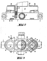
- FIG. 2 shows a side view of the arrangement of FIG. 1, for example from the front, with the mixing valve shown broken off.
- the base part 1 contains lateral, in Fig. 2 in Cut-to-see lugs 33 with holes 34 through which the base part 1 on a base, for example, the rear wall of a wall recess, can be screwed.
- Fig. 3 shows an end view, wherein in the right half of Fig. 3, the fitting body 17 is attached to the base part 1, while in the left half of Fig. 3, the separating surface 13 forming the front side 9 of the base part can be seen. On the left, the groove 14 can be seen at the passage opening 10, which surrounds the opening 10 coaxially with a certain distance and is intended to receive a seal.
- the safety insert 26 On the right in FIG. 3, the safety insert 26 can be seen.
- the safety insert has in its peripheral region two diametrically arranged notches 36 for insertion of a tool, with which it is screwed into the corresponding opening in the thread 25.
- the screwed into the safety insert 26, to the outside by an end wall 37 closed inner sleeve 31 has in this end wall 37 a diametrically extending groove 38, which can serve for insertion of a tool or a key, so that the inner sleeve 31 are rotated relative to the security set 26 can.
- the inner sleeve can be used in the manner already described to turn off the flow of water through the safety insert 26 so that the mixing valve can be inserted or removed when the fitting body is mounted.
- Fig. 4 shows a longitudinal section through the base part 1 of the sanitary fitting according to the invention in the manner in which the fitting is supplied to the installer, so that they can install them. From the base part 1 of the fitting body 17 is removed. In the flat parting surface 13, the corresponding seals are inserted in the grooves 14, 15 and 16. Instead of the main body of the fitting, a flushing block 39 is screwed to the base part 1.
- the flushing block 39 has passage openings for the fastening screws 19. These engage in the aforementioned threaded bores 35.
- the flushing block 39 has three connections 40 with internal thread 41 on its front side facing away from the base part.
- Each terminal 40 is associated with a passage opening 10, 11, 12 of the base part 1.
- the terminals or the through openings 10 surrounding intermediate walls 42 are present, which are arranged or formed so that they cooperate with the arranged in the grooves 14 to 16 seals.
- each terminal sealed over an opening 10 to 12 leads exactly to one of the formed in the base part 1 interior spaces 5, 6, 7. So you can close the terminals 40 by plugs or attach pressure gauge and apply pressure elsewhere in the line installation to thereby checking the individual branches of the lines for pressure.
- the flushing block 39 is housed together with the base part 1 in a flush-mounted box 43, which has on its outer side a circumferential flange 44.
- the assembly of the base part 1 therefore takes place in a wall opening together with the flush-mounted box 43.
- plastering the wall and / or tiling the wall surface can be performed. Only when these measures are all completed, the protruding over the top of the wall part of the flush-mounted box 43 is separated and the flushing block 39 unscrewed.
- the main body of the fitting which can be completely factory-fitted, is attached to the parting surface 13 of the base part 1, whereby the end regions 29 of the safety inserts 26 are threaded through the associated through-openings 10, 11. Subsequently, the screw is done.
- the flushing block 39 is designed so that it lies with its edge flange directly within the edge flange of the flush-mounted box. He is at a close distance from the edge of the flush-mounted box inserted into this.
- the flushing block 39 could also form the lid of the flush-mounted box.
- flushing block 39 extends with its edge region up to the side of the base part 1 facing the wall, so that the flushing block 39 practically surrounds the base part 1 like a flush-mounted box.
- flushing block 39 with a surrounding the base part of the fitting Isolierverschalung, in which case the Spülblock 39 and the insulation form a transport packaging.
- the insulating part can then remain in the wall after mounting, while the flushing block 39 is then removed.
Abstract
Description
Die Erfindung geht aus von einer Sanitärarmatur, die insbesondere zur Unterputzmontage geeignet ist.The invention relates to a sanitary fitting, which is particularly suitable for flush mounting.
Es ist bereits ein thermostatisches Mischventil dieser Art bekannt (DE 38 19 420 A1), bei dem das Gehäuse des Mischventils in ein Anschlußgehäuse mit drei Anschlüssen und ein Aufsatzgehäuse unterteilt ist. Das Anschlußgehäuse weist drei Verbindungsöffnungen für Ansätze des Aufsatzgehäuses auf, wobei die Dichtung innerhalb der zylindrischen Mantelflächen der Verbindungsöffnungen geschieht.It is already a thermostatic mixing valve of this type known (
Ebenfalls bekannt ist eine sanitäre Armatur, die in einem Unterputz-Einbaukasten angebracht werden kann (CH 661 551 A5). Hier enthält die Armatur einen Bacickörper, der alle nötigen Öffnungen und-Durchbrechungen aufweist, in die die Absperrorgane und das Mischventil eingesetzt werden können.Also known is a sanitary fitting, which can be mounted in a concealed installation box (CH 661 551 A5). Here, the fitting contains a Bacickörper having all the necessary openings and openings, in which the shut-off valves and the mixing valve can be used.
Weiterhin ist eine Anschiußanordnung für eine sanitäre Mischarmatur bekannt (DE-A1-3826064), bei der ein Basisteil eine Trennfläche zur Verbindung mit einem Armaturengrundkörperaufweist. Die Trennfläche dient dazu, die beiden Teile miteinander zu verschrauben. Zwischen dem Basisteil und dem Armaturengrundkörper ist ein Einsatz vorgesehen, der die Wasserführung zwischen dem Basisteil und dem Armaturengrundkörper übernimmt.Furthermore, a Anschiußanordnung for a sanitary mixing fitting is known (DE-A1-3826064), in which a base part has a parting surface for connection to a valve body. The separating surface serves to screw the two parts together. Between the base part and the fitting body an insert is provided, which takes over the water supply between the base part and the fitting body.
Weiterhin ist eine Anschlußvorrichtung für eine sanitäre Mischarmatur bekannt (EP-A1-576391), bei der ein Anschlußgehäuse mit Anschlüssen für Kalt- und Warmwasser vorhanden ist. An dem Anschlußgehäuse kann ein Armaturengehäuse befestigt werden. Zwischen dem Anschlußgehäuse und dem Armaturengehäuse ist ein Verbindungsstück vorhanden, das die Wasserführung zwischen dem Anschlußgehäuse und dem Armaturengehäuse übernimmt.Furthermore, a connection device for a sanitary mixing fitting is known (EP-A1-576391), in which a connection housing with connections for cold and hot water is present. At the connection housing a fitting housing can be attached. Between the terminal housing and the fitting housing, a connecting piece is provided, which takes over the flow of water between the terminal housing and the valve body.
Der Erfindung liegt die Aufgabe zugrunde, eine Sanitärarmatur zu schaffen, die sich einfach montieren läßt, dem Installateur eine komfortable Möglichkeit bietet, die vorgeschriebene Leitungsspülung vorzunehmen, und die auch in montiertem Zustand die einfache Möglichkeit der Wartung bietet.The invention has for its object to provide a sanitary fitting that can be easily installed, the installer provides a convenient way to make the prescribed line flushing, and even in the assembled state offers easy maintenance.
Zur Lösung dieser Aufgabe schlägt die Erfindung eine sanitäre Mischarmatur mit den im Anspruch 1 bzw. 2 aufgeführten Merkmalen vor. Weiterbildungen der Erfindung sind Gegenstand von abhängigen Ansprüchen.To solve this problem, the invention proposes a sanitary mixing fitting with the features listed in
Die von der Erfindung vorgeschlagene Sanitärarmatur wird so montiert, daß zunächst das Basisteil ohne den Armaturengrundkörper mit den in einer Wandöffnung vorhandenen Installationsleitungen der Hausinstallation verbunden wird. Sobald dies erfolgt ist und eine möglicherweise vorhandene Verfliesung vervollständigt ist, wird anschließend der Armaturengrundkörper an dem Basisteil angebracht, beispielsweise mit Hilfe von Schrauben festgeschraubt. Anschließend kann dann eine Abdeckrosette oder eine sonstige Abdeckung angebracht werden. Das Abnehmen des Armaturengrundkörpers ist auch weiterhin noch möglich.The sanitary fitting proposed by the invention is mounted so that first the base part is connected without the fitting body with the present in a wall opening installation lines of the house installation. Once this is done and a possibly existing tiling is completed, then the fitting body is attached to the base part, for example screwed by means of screws. Subsequently, a cover rosette or other cover can be attached. The removal of the fitting body is still possible.
Das Basisteil dient also ausschließlich zur Verbindung mit der Hauswasserinstallation, während die verschiedenen Durchgänge zur Verbindung mit den Teilen des Mischventils in dem Armaturengrundkörper angeordnet sind. Es wird möglich, mit einem Basisteil für mehrere unterschiedlich gestaltete Armaturengrundkörper auszukommen.The base part thus serves exclusively for connection to the domestic water installation, while the various passages for connection to the parts of the mixing valve are arranged in the fitting body. It is possible to make do with a base part for several different designed basic body fittings.
Insbesondere kann vorgesehen sein, daß die einander zugeordneten Trennflächen des Basisteils und des Armaturengrundkörpers als ebene Flächen ausgebildet sind. Dies kann die Montage erleichtern, da es nicht mehr erforderlich ist, vorspringende Teile In entsprechende Vertiefungen einzufädeln.In particular, it can be provided that the mutually associated separating surfaces of the base part and the fitting body are formed as flat surfaces. This can facilitate assembly, as it is no longer necessary to thread protruding parts into corresponding recesses.
In nochmaliger Weiterbildung der Erfindung kann vorgesehen sein, daß die Durchtrittsöffnungen und/oder die Durchgangsöffnungen in mindestens einer der Trennflächen von Nuten zur Aufnahme von Dichtungen umgeben sind. Die Anbringung der Dichtungen in Nuten innerhalb einer ebenen Fläche hat den Vorteil, daß beim Anbringen des Armaturengrundkörpers an dem Basisteil nicht die Gefahr besteht, daß Dichtungen gequetscht und möglicherweise auch beschädigt werden.In a further development of the invention can be provided that the passage openings and / or the passage openings are surrounded in at least one of the parting surfaces of grooves for receiving seals. The attachment of the seals in grooves within a flat surface has the advantage that when attaching the fitting body to the base member there is no risk that seals are crushed and possibly damaged.
Insbesondere kann nach einem weiteren Vorschlag der Erfindung vorgesehen sein, daß die Nuten zur Aufnahme der Dichtungen in der Trennfläche des Basisteils angeordnet sind.In particular, it can be provided according to a further proposal of the invention that the grooves for receiving the seals are arranged in the parting surface of the base part.
Die Erfindung kann bei Sanitärarmaturen Anwendung finden, bei denen das Mischwasser aus der Armatur direkt entnommen wird. Sie kann aber ebenfalls mit Vorteil bei solchen Armaturen Anwendung finden, bei denen das Mischwasser wiederum durch eine unter Putz durch die Wand geführte Leitung entnommen wird. Für diesen Fall kann vorgesehen sein, daß das Basisteil mindestens einen weiteren Anschluß für eine von der Armatur wegführende Mischwasserleitung und die Trennfläche eine zugeordnete Durchtrittsöffnung für das Mischwasser aufweist, die mit dem Aufnahmeraum für das Mischventil verbunden ist. Auch diese Durchtrittsöffnung kann in der erwähnten Weise abgedichtet werden.The invention can be found in sanitary fittings application in which the mixed water is removed directly from the valve. However, it can also be used with advantage in such fittings application in which the mixed water is again removed by a guided under plaster through the wall line. For this case, it can be provided that the base part has at least one further connection for a mixing water line leading away from the fitting and the separating surface has an associated through-opening for the mixed water, which is connected to the receiving space for the mixing valve. Also, this passage opening can be sealed in the manner mentioned.
Selbstverständlich ist es auch möglich, daß das Basisteil eine weitere wegführende Mischwasserleitung aufweist, die beispielsweise zu einer Handbrause führt, während die erste Mischwasserleitung zu einem Wannenauslauf führt.Of course, it is also possible that the base part has a further leading away mixed water line, which leads, for example, to a hand shower, while the first mixed water line leads to a trough outlet.
Insbesondere schlägt die Erfindung vor, daß der Grundkörper von dem Basisteil in dessen montiertem Zustand wieder lösbar una abnehmbar und auch wieder anbringbar sein kann.In particular, the invention proposes that the main body of the base part in its mounted state can be releasably una removable and also attachable again.
Zur Erleichterung der Installation kann vorgesehen sein, daß an dem Basisteil anstelle des Armaturengrundkörpers ein Spülblock angebracht werden kann, der zu den Durchtrittsöffnungen des Basisteils führende, ggf. durch Stopfen verschließbare Anschlüsse aufweist. Dieser Spülblock kann dazu dienen, nach Herstellung der Installation die Installation auf Dichtigkeit zu überprüfen. So lassen sich beispielsweise an den Anschlüssen Manometer oser Druckschläuche anbringen. Dieses Überprüfen der Hausinstallation auf Dichtigkeit geschieht am Sinnvollsten ohne den Armaturengrundkörper.To facilitate the installation can be provided that a flushing block can be attached to the base part instead of the fitting body, which has leading to the passage openings of the base part, possibly closed by plug connections. This flushing block can be used after installation of the installation for leakproofing to check. For example, pressure gauges can be attached to the connections at the connections. This check of the house installation for leaks is done most sensibly without the fitting body.
Der erwähnte Spülblock kann weiterhin zum Schutz der Armaturwährend des Fertigstellens des Verputzes und der Verfliesung dienen. Daher wird erfindungsgemäß die Sanitärarmatur in der Weise geliefert, daß an dem Basistell der Spülblock angebracht ist. Dies geschieht vorteilhafterweise mit Hilfe der gleichen Befestigungsmittel, die auch zum Befestigen des Armaturengrundkörpers dienen, also beispielsweise mit Schrauben. Diese können dann zu dem erwähnten Zweck weiter verwendet werden.The mentioned flushing block may further serve to protect the fitting during completion of the plastering and tiling. Therefore, according to the invention, the sanitary fitting is provided in such a way that is attached to the base of the rinse block. This is advantageously done with the help of the same fastening means, which also serve to fasten the fitting body, so for example with screws. These can then be used for the purpose mentioned.
Insbesondere kann erfindungsgemäß vorgesehen sein, daß bei montiertem Spülblock die Durchtrittsöffnungen der Trennfläche des Basisteils durch Trennwände des Spülblocks gegenseitig abgedichtet sind. Dadurch kann ein getrenntes Überprüfen der einzelnen Leitungszweige auf Dichtigkeit erfolgen. Nach Durchführung der Überprüfung des Leitungssystems und Herstellung der Verfliesung wird dann der Spülblock entfernt und der Armaturengrundkörper, ggf. zusammen mit dem in ihm bereits untergebrachten Mischventil, befestigt.In particular, it can be provided according to the invention that when the flushing block is mounted, the passage openings of the parting surface of the base part are mutually sealed by partitions of the flushing block. As a result, a separate check of the individual line branches for tightness. After carrying out the inspection of the line system and production of the tiling then the flushing block is removed and the main body of the fixture, possibly together with the mixing valve already accommodated in it, attached.
Insbesondere kann der Spülblock derart ausgebildet sein, daß er den Deckel eines Unterputzkastens bildet. Dies kann beispielsweise auch dadurch geschehen, daß er mit dem Unterputzkasten direkt verbunden ist, so daß er nach Montage von diesem abgetrennt wird.In particular, the flushing block can be designed such that it forms the lid of a flush-mounted box. This can for example also be done by being directly connected to the flush-mounted box, so that it is separated after assembly of this.
Nach Abnahme oder Abtrennung des Spülblocks nach der Installation kann dieser vom Installateur an den Hersteller zur Wiederverwendung oder zum Recycling zurückgegeben werden. Bei der Wiederverwendung braucht der Hersteller nur die vom Installateur aus den Anschlüssen herausgenommenen und nicht zurückgebrachten Stopfen erneut einzusetzen.After removal or removal of the purge block after installation, it may be returned by the installer to the manufacturer for reuse or recycling. For reuse, the manufacturer only needs to reuse the plugs taken out of the terminals by the installer and not returned.
Der Spülblock könnte auch so ausgebildet werden, daß er das Armaturenbasisteil in dessen Außenkonturen so weit umschließt, daß ein eigenes Unterputzgehäuse nicht mehr erforderlich ist.The flushing block could also be designed so that it encloses the valve base part in its outer contours so far that a separate flush-mounted housing is no longer required.
Außerdem ist es möglich, den Spülblock derart mit einer das Basisteil der Armatur umgebenden Isolierung zu kombinieren, daß Spülblock und Isolierung zusammen gleichzeitig eine Verpackung für das Basisteil bilden.In addition, it is possible to combine the flushing block with an insulation surrounding the base part of the fitting in such a way that the flushing block and insulation together simultaneously form a packaging for the base part.
Nach Montage kann der Spülblock oder ein Teil des Spülblocks von der Isolierung und von dem Basisteil abgenommen werden, wobei die Isolierung dann in der Wand verbleiben kann.After assembly, the flushing block or a part of the flushing block can be removed from the insulation and from the base part, wherein the insulation can then remain in the wall.
Ein erfindungswesentliches Merkmal besteht darin daß der Armaturengrundkörper je einen Sicherheitseinsatz, für den Kaltwasser- und den Warmwasser-Durchgang des Armaturengrundkörpers aufweist und die Wasserführung durch den Sicherheitseinsatz hindurchgeht. Der Sicherheitseinsatz kann beispielsweise einen Rückflußverhinderer, ein Sieb oder eine Druckreduzierung enthalten.A feature essential to the invention is that the fitting body has ever a safety insert for the cold water and the hot water passage of the fitting body and the water passage passes through the safety insert. The safety insert may, for example, contain a backflow preventer, a sieve or a pressure reduction.
Es kann bei einer Sanitärarmatur mit den Merkmalen des Anspruchs 1 vorgesehen sein, dass der Sicherheitseinsatz über die Trennfläche des Armaturengrundkörpers hinaus in die Durchtrittsöffnung des Basisteils hinein ragt.
Dadurch, dass der Sicherheitseinsatz über die Trennfläche des Armaturengrundkörpers hinaus in die Durchtrittsöffnung des Basisteils hinein ragt, lässt sich trotz des Aufbaus aus mehreren Teilen eine flache Bauart ermöglichen. Falls die Abdichtung in der ebenen, die Durchtrittsöffnung umgebenden Trennfläche erfolgt, können die hineinragenden Teile des Sicherheitseinsatzes einen gewissen Abstand von den Rändern der Durchtrittsöffnung aufweisen, so dass das leichte Einsetzen und Verbinden von Basisteil und Armaturengrundkörper hierdurch nicht beeinträchtigt wird.It may be provided in a sanitary fitting with the features of claim 1, that the safety insert projects beyond the parting surface of the fitting main body out into the passage opening of the base part.
Due to the fact that the safety insert protrudes into the passage opening of the base part beyond the separating surface of the fitting body, a flat design can be made possible despite the construction of several parts. If the sealing takes place in the planar, the passage opening surrounding the separating surface, the protruding parts of the safety insert may have a certain distance from the edges of the passage opening, so that the easy insertion and connection of the base member and fitting body is not affected.
Erfindungsgemäß kann bei einer Mischarmatur mit den Merkmalen des Anspruchs 2 vorgesehen sein, dass der Sicherheitseinsatz eine Absperreinrichtung aufweist.
Die Absperreinrichtung des Sicherheitseinsatzes kann zum Absperren der Wasserzuführung benutzt werden, so dass auch bei montierter Sanitärarmatur ohne Abstellen eines Hauptventils das Mischventil entfernt oder ausgetauscht werden kann.According to the invention may be provided in a mixing valve with the features of
The shut-off device of the safety insert can be used to shut off the water supply, so that even with mounted sanitary fitting without switching off a main valve, the mixing valve can be removed or replaced.
Insbesondere schlägt die Erfindung bei einer Mischarmatur mit den Merkmalen des Anspruchs 2 vor, dass die Absperreinrichtung des Sicherheitseinsatzes bei montiertem Armaturengrundkörper von außen her noch zugänglich ist.In particular, the invention proposes in a mixing fitting with the features of
In nochmaliger Weiterbildung der Erfindung nach Anspruch 1 kann vorgesehen sein, dass der Sicherheitseinsatz von der der Trennfläche des Armaturengrundkörpers abgewandten Vorderseite her in diesen einsetzbar, beispielsweise einschraubbar, ist.In a further development of the invention according to claim 1, it can be provided that the safety insert can be inserted, for example screwed in, from the front side facing away from the separating surface of the fitting body.
Erfindungsgemäß kann in Weiterbildung die Art der Verbindung zwischen dem Basisteil und dem Armaturengrundkörper so ausgebildet werden, daß bei ungeänderter Stellung des Armaturengrundkörpers, insbesondere des Mischventils, das Basisteil in mindestens zwei verschiedenen Stellungen mit der Hausinstallation verbunden werden kann.According to the invention, the type of connection between the base part and the fitting body can be formed so that in unchanged position of the valve body, in particular the mixing valve, the base part can be connected in at least two different positions with the house installation.
Dies gilt insbesondere für den Mischwasserabgang, insbesondere dann, wenn an diesen bereits ein Absperr- oder Umstellorgan oder beides angebracht ist. Diese Organe werden in der Praxis je nach Vorliebe des Installateurs oder den örtlichen Gegebenheiten, entweder nach oben oder nach unten installiert. Hier ist es dann sinnvoll, den Armaturengrundkörper gegenüber dem Basisteil in verschiedenen Stellungen anordnen zu können, damit nach Fertigstellung der Installation das Bedienelement zum Benutzer hin immer die gleiche griffgünstige Lage hat.This is especially true for the mixed water outlet, especially if it already has a shut-off or Umstellorgan or both attached. These organs are installed in practice, depending on the installer's preference or the local conditions, either up or down. Here it makes sense then to be able to arrange the fitting body relative to the base part in different positions, so that after completion of the installation, the operating element to the user always has the same convenient position.
Es wäre denkbar, daß zum Beispiel an einer Badewanne der Mischwasserabgang nach unten montiert wird, während in der unmittelbar daneben installierten Dusche der Abgang nach oben montiert wird. Es kann dann für den Benutzer gewährleistet werden, daß die Bedienung an beiden Armaturen gleich ist.It is conceivable that, for example, on a bathtub, the mixed water outlet is mounted down, while in the immediately adjacent installed shower the outlet is mounted upwards. It can then be ensured for the user that the operation of both valves is the same.
Was hier zu der Möglichkeit des Umdrehens im Hinblick auf den Mischwasseranschluß gesagt wurde, gilt natürlich auch für die Zuleitungen.What has been said here about the possibility of turning around with regard to the mixed water connection, of course, also applies to the supply lines.
Weitere Merkmale, Einzelheiten und Vorzüge ergeben sich aus den Patentansprüchen, deren Wortlaut durch Bezugnahme zum Inhalt der Beschreibung gemacht wird, derfolgenden Beschreibung einer bevorzugten Ausführungsform der Erfindung sowie anhand der Zeichnung. Hierbei zeigen:
- Fig. 1
- einen schematischen Längsschnitt durch eine Sanitärarmatur nach der Erfindung;
- Fig. 2
- eine Seitenansicht der Armatur der Fig. 1 von vorne in Fig. 1;
- Fig. 3
- eine Aufsicht auf die Armatur aus Richtung des Bedienelements mitteilweise weggelassenem Armaturengrundkörper;
- Fig. 4
- einen der Fig. 1 entsprechenden Längsschnitt durch das Basisteil des Armaturengrundkörpers mit aufgesetztem Spülblock in einem Unterputzkasten.
- Fig. 1
- a schematic longitudinal section through a sanitary fitting according to the invention;
- Fig. 2
- a side view of the valve of Figure 1 from the front in Fig. 1.
- Fig. 3
- a plan view of the valve from the direction of the control part teilteilem omitted basic body;
- Fig. 4
- 1 corresponding longitudinal section through the base part of the fitting body with attached rinsing block in a flush-mounted box.
Die in Fig. 1 im Schnitt dargestellte Sanitärarmatur enthält ein Basisteil 1, das zur Montage unter Putz geeignet und bestimmt ist. Das Basisteil 1 enthält in seinem in Fig. 1 oberen Bereich einen ersten Anschluß 2 mit einem Innengewinde 3 zur Verbindung mit einer in der Wand geführten Wasserleitung, beispielsweise für kaltes Wasser.The sanitary fitting shown in section in Fig. 1 contains a base part 1, which is suitable for installation under plaster and determined. The base part 1 contains in its upper part in Fig. 1 a
An der gegenüberliegenden Seite enthält das Basisteil einen zweiten Anschluß 4 ebenfalls mit einem Innengewinde 3 zum Anschluß an eine zweite Leitung, in diesem Fall also die Warmwasserleitung.On the opposite side, the base part includes a second terminal 4 also with an internal thread 3 for connection to a second line, in this case the hot water pipe.
Innerhalb des Basisteils 1 führt der erste Anschluß 2 in einen abgeschlossenen Innenraum 5, während der zweite Anschluß 4 zu einem abgeschlossenen Innenraum 6 führt.Within the base part 1, the
In dem Basisteil 1 ist ein dritter Innenraum 7 angeordnet, in den ein nur angedeuteter Anschluß 8 führt. Hierbei kann es sich beispielsweise um eine zu einem Wannenauslauf führende Mischwasserleitung handeln.In the base part 1, a third
Das Basisteil 1 der Armatur ist so ausgebildet, daß seine in Fig. 1 rechte Seite zum Boden einer Wandöffnung führt, während die gegenüberliegende, in Fig. 1 linke Vorderseite 9 als über ihren größten Teil ebene Trennfläche ausgebildet ist. In dieser ebenen, als Trennfläche ausgebildeten Vorderseite 9 münden aus jedem Innenraum 5, 6, 7 je eine Durchtrittsöffnung 10, 11, 12, siehe insbesondere die Fig. 3, in der diese Durchtrittsöffnungen 10, 12 zu sehen sind.The base part 1 of the fitting is formed so that its right in Fig. 1 side leads to the bottom of a wall opening, while the opposite, in Fig. 1 left front 9 is formed over its largest part flat separating surface. In this flat, designed as a separating surface front side 9 open from each interior 5, 6, 7 each have a
Jede Durchtrittsöffnung 10, 11, 12 ist in der als Trennfläche 13 ausgebildeten ebenen Vorderseite 9 des Basisteils 1 von einer konzentrisch zu der Durchtrittsöffnung verlaufenden Nut 14, 15, 16 umgeben, in der jeweils ein Dichtring eingelegt ist.Each
Von der Vorderseite her, in Fig. 1 also von links, ist an dem Basisteil 1 ein Armaturengrundkörper 17 befestigt, dessen dem Basisteil 1 zugewandte Rückseite eine ebenfalls ebene Trennfläche 18 bildet. In dieser Trennfläche 18 münden ebenfalls Durchgänge für Wasser, wie im folgenden noch erläutert wird. Das Befestigen des Armaturengrundkörpers 17 geschieht mit Hilfe von in den Basisteil 1 eingreifenden Schrauben 19 mit Schraubenköpfen 20, siehe auch Fig. 2 und 3.From the front side, ie from the left in FIG. 1, a
Der Armaturengrundkörper weist von den Durchgangsöffnungen ausgehende Durchgänge 21 und 22 auf, die zu einer Aufnahme für ein Thermostat-Mischventil 23 führen. Das Mischventil 23 ist von der Vorderseite her in den Armaturengrundkörper 17 eingeschraubt. Von der Außenseite her ist es mit Hilfe eines Bediengriffes 24 verstellbar.The fitting main body has
Der Armaturengrundkörper 17 weist in axialer Verlängerung seiner Durchgangsöffnungen je eine mit einem Gewinde 25 versehene Öffnung auf, in die ein Sicherheitseinsatz 26 von der Vorderseite des Armaturengrundkörpers her eingeschraubt ist. Dieser Sicherheitseinsatz 26 ist gegenüber dem Armaturengrundkörper mit Hilte einer Dichtung 27 abgedichtet. Der Sicherheitseinsatz 26 ist im Bereich der Durchgangsöffnungen diesem gegenüber mit einer weiteren Dichtung 28 abgedichtet. Hier sind die Dichtungen 27, 28 in Nuten untergebracht, die in zylindrischen Mantelflächen liegen. Dies ist an dieser Stelle nicht kritisch, da das Befestigen der Sicherheitseinsätze 26 im Armaturengrundkörper 17 fabrikmäßig erfolgt.The
Die Sicherheitseinsätze 26 ragen mit ihrem zu dem Basisteil gerichteten Endbereich 29 über die Trennfläche 18 hinaus und durch die Durchtrittsöffnungen 10, 11 hindurch in die Innenräume 5 bzw. 6 des Basisteils 1 hinein. Dadurch wird trotz der eine gewisse Baulänge aufweisenden Sicherheitseinsätze 26 eine geringe Bautiefe derArmatur erreicht. Zwischen der Außenseite der Sicherheitseinsätze 26 und dem Umfang der Durchtrittsöffnungen 10, 11 kann ein Spiel vorhanden sein, da die Abdichtung durch die Dichtungen 14, 15 erfolgt.The safety inserts 26 protrude with their
In der Figur sind die beiden Sicherheitseinsätze 26 längs einer Mittellinie in ihren beiden möglichen Stellungen gezeichnet. In jedem Sicherheitseinsatz 26 ist ein Sieb 30 angeordnet, durch das das Wasser in die Durchgänge 21, 22 gelangen kann. Jeder Sicherheitseinsatz 26 weist eine Innenhülse 31 auf, die gegenüber dem Einsatz 26 abgedichtet ist und mit diesem über ein Gewinde verbunden ist. Durch Verdrehen der Innenhülse 31 kann diese in der Fig. 1 nach links bewegt werden, bis an dem in das Basisteil hineinragenden Ende eine dort angeordnete Ventilplatte 32 einen Durchtritt des Wassers verhindert. Durch Verdrehen der Innenhülse 31 in umgekehrte Richtung wird die Ventilplatte 32 von einer Schulter 33 abgehoben, so daß das Wasser an der Schulter 33 durch radiale Öffnungen der Innenhülse 31 in diese einströmen kann. Innerhalb der Innenhülse 31 ist ein Rückflußverhinderer 33 eingebaut.In the figure, the two
Fig. 2 zeigt eine Seitenansicht der Anordnung der Fig. 1, beispielsweise von vorne, mit abgebrochen dargestelltem Mischventil.FIG. 2 shows a side view of the arrangement of FIG. 1, for example from the front, with the mixing valve shown broken off.
Das Basisteil 1 enthält seitliche, in Fig. 2 im Schnitt zu sehende Ansätze 33 mit Löchern 34, durch die hindurch das Basisteil 1 an einer Unterlage, beispielsweise der Rückwand einer Wandausnehmung, angeschraubt werden kann.The base part 1 contains lateral, in Fig. 2 in Cut-to-see
In dem Basisteil 1 sind mit Gewinde versehene Sacklöcher 35 vorhanden, die zur Aufnahme der Schrauben 19 dienen, mit denen der Armaturengrundkörper 17 am Basisteil 1 angeschraubt wird.In the base part 1 threaded
Fig. 3 zeigt eine Stirnansicht, wobei in der rechten Hälfte der Fig. 3 der Armaturengrundkörper 17 an dem Basisteil 1 angebracht ist, während in der linken Hälfte der Fig. 3 die die Trennfläche 13 bildende Vorderseite 9 des Basisteils zu sehen ist. Links ist bei der Durchtrittsöffnung 10 die Nut 14 zu sehen, die die Öffnung 10 koaxial mit einem gewissen Abstand umgibt und zur Aufnahme einer Dichtung bestimmt ist.Fig. 3 shows an end view, wherein in the right half of Fig. 3, the
Rechts in Fig. 3 ist der Sicherheitseinsatz 26 zu sehen. Der Sicherheitseinsatz weist in seinem Umfangsbereich zwei diametral angeordnete Kerben 36 zum Einsetzen eines Werkzeugs auf, mit denen er in die entsprechende Öffnung in das Gewinde 25 eingeschraubt wird.On the right in FIG. 3, the
Die in dem Sicherheitseinsatz 26 eingeschraubte, zur Außenseite hin durch eine Stirnwand 37 abgeschlossene Innenhülse 31 weist in dieser Stirnwand 37 eine diametral verlaufende Nut 38 auf, die zum Einsetzen eines Werkzeugs oder eines Schlüssels dienen kann, damit die Innenhülse 31 gegenüber dem Sicherheitsetnsatz 26 verdreht werden kann. Damit kann die Innenhülse in der bereits geschilderten Weise dazu verwendet werden, die Strömung des Wassers durch den Sicherheitseinsatz 26 abzustellen, damit bei montiertem Armaturengrundkörper das Mischventil eingesetzt oder herausgenommen werden kann.The screwed into the
Fig. 4 zeigt einen Längsschnitt durch das Basisteil 1 der erfindungsgemäßen Sanitärarmatur in der Weise, wie die Armatur dem Installateur geliefert wird, damit dieser sie installieren kann. Von dem Basisteil 1 ist der Armaturengrundkörper 17 abgenommen. In der ebenen Trennfläche 13 sind in den Nuten 14, 15 und 16 die entsprechenden Dichtungen eingesetzt. Anstelle des Armaturengrundkörpers ist mit dem Basisteil 1 ein Spülblock 39 verschraubt. Der Spülblock 39 weist Durchgangsöffnungen für die Befestigungsschrauben 19 auf. Diese greifen in die erwähnten Gewindebohrungen 35 ein.Fig. 4 shows a longitudinal section through the base part 1 of the sanitary fitting according to the invention in the manner in which the fitting is supplied to the installer, so that they can install them. From the base part 1 of the
Der Spülblock 39 weist an seiner dem Basisteil abgewandten Vorderseite drei Anschlüsse 40 mit Innengewinde 41 auf. Jeder Anschluß 40 ist einer Durchtrittsöffnung 10, 11, 12 des Basisteils 1 zugeordnet. Zwischen den einzelnen Anschlüssen 40 sind die Anschlüsse bzw. die Durchtrittsöffnungen 10 umgebende Zwischenwände 42 vorhanden, die so angeordnet bzw. ausgebildet sind, daß sie mit den in den Nuten 14 bis 16 angeordneten Dichtungen zusammenwirken. Dadurch führt jeder Anschluß abgedichtet über eine Öffnung 10 bis 12 genau zu einem der in dem Basisteil 1 ausgebildeten Innenräume 5, 6, 7. Man kann also die Anschlüsse 40 durch Stopfen verschließen oder Manometer anbringen und an einer anderen Stelle der Leitungsinstallation Druck aufbringen, um dadurch die einzelnen Zweige der Leitungen auf Druck zu überprüfen.The
Der Spülblock 39 ist zusammen mit dem Basisteil 1 in einem Unterputzkasten 43 untergebracht, der an seiner Außenseite einen umlaufenden Flansch 44 aufweist. Die Montage des Basisteils 1 geschieht daher in einer Wandöffnung zusammen mit dem Unterputzkasten 43. Nach Verbinden des Basisteils 1 mit den Leitungen der Installation und dem Überprüfen der Installation auf Dichtigkeit kann dann ein Verputzen der Wand und/oder ein Verfliesen der Wandoberfläche durchgeführt werden. Erst wenn diese Maßnahmen alle beendet sind, wird der über die Wandoberseite vorstehende Teil des Unterputzkastens 43 abgetrennt und der Spülblock 39 abgeschraubt. Dann wird mit Hilfe derselben Schrauben 19 der Armaturengrundkörper, der fabrikmäßig vollständig montiert sein kann, an die Trennfläche 13 des Basisteils 1 angesetzt, wobei die Endbereiche 29 der Sicherheitseinsätze 26 mit Spiel durch die zugehörigen Durchtrittsöffnungen 10, 11, hindurchgefädelt werden. Anschließend erfolgt die Verschraubung.The
Bei der Ausführungsform in Fig. 4 ist der Spülblock 39 so gestaltet, daß er mit seinem Randflansch unmittelbar innerhalb des Randflansches des Unterputzkastens liegt. Er ist mit dichtem Abstand von dem Rand des Unterputzkastens in diesen eingesetzt. Der Spülblock 39 könnte auch den Deckel des Unterputzkastens bilden.In the embodiment in Fig. 4, the
Ebenfalls möglich wäre es, daß der Spülblock 39 mit seinem Randbereich bis zu der der Wand zugewandten Seite des Basisteils 1 reicht, so daß der Spülblock 39 das Basisteil 1 praktisch wie ein Unterputzkasten umgibt.It would also be possible that the
Ebenfalls möglich ist es, den Spülblock 39 mit einer das Basisteil der Armatur umgebenden Isolierverschalung zu kombinieren, wobei dann der Spülblock 39 und die Isolierung eine Transportverpackung bilden. Der Isolierteil kann dann nach Montage in der Wand verbleiben, während der Spülblock 39 dann abgenommen wird.It is also possible to combine the
Claims (15)
- Sanitary fitting, with1.1 a basic part (1) particularly meant for hidden installation, which features1.1.1 a connection (2) for a hot water pipe and a connection (4) for a cold water pipe and1.1.2 a partition surface (13) accessible in the mounted state of the basic part,1.2 a fitting body (17),1.2.1 which is fixable on the basic part (1),1.2.2 with a partition surface (18) interacting with the partition surface (13) of basic part (1) and1.2.3 features a receiving space for a mixing valve (23), in which1.2.3.1 openings for cold and warm water are provided, as well as1.3 a mixing valve (23), which is usablecharacterised in that1.3.1 in the receiving space,1.4 the partition surfaces (13, 18) of the basic part (1) interacting with one another and of the fitting body (17) feature passage openings (10, 11) for warm and cold water, corresponding with one another,1.5 the fitting body (17) that features a safety cartridge (26), each for the cold water and warm water passage,1.6 the water delivery passes through the safety cartridge (26) and1.7 the safety cartridge (26) features a fitting body (17) accessible in the case of a mounted accessible shut-off equipment.
- Sanitary fitting, with2.1 a basic part (1) particularly meant for hidden installation, which features2.1.1 a connection (2) for a hot water pipe and a connection (4) for a cold water pipe and2.1.2 a partition surface (13) accessible in mounted state of the basic part,2.2 a fitting body (17), which2.2.1 is fixable on the basic part (1),2.2.2 a partition surface (18) interacting with the partition surface (13) of basic part (1) and2.2.3 features a receiving space for a mixing valve (23), in which2.2.3.1 openings for cold and warm water delivery, as well as2.3 a mixing valve (23), whichcharacterised in that2.3.1 is usable in the receiving space,2.4 the mutually interacting partition surfaces (13,18) of the basic part (1) and the fitting body (17) feature corresponding passage openings (10,11) for warm and cold water,2.5 the fitting body (17) features a safety cartridge (26) each for cold water and for warm water passage,2.6 the water delivery occurs through the safety cartridge (26),2.7 the safety cartridge (26) projects through the partition surface (18) of the fitting body (17) into the passage opening(s) (10, 11) of the basic part (1) and2.8 from the front side of the fitting body (17) facing away from the partition surface (18) of the fitting body (17), is insertable into the latter.
- Sanitary fitting according to claim 1 or 2, wherein the partition surfaces (13, 18) are plane.
- Sanitary fitting according to one of claims 2 to 4, wherein the passage openings (10,11) at least in one of the partition surfaces (13,18) are surrounded by grooves (14,15) for receiving seals.
- Sanitary fitting according to claim 4, wherein the grooves (14, 15) are arranged in the partition surface (13) of basic part (1).
- Sanitary fitting according to one of the preceding claims, wherein the basic part (1) features at least one further connection (8) for a mixed water pipe leading away from the fitting and the partition surface (13) a corresponding passage opening (12) for mixed water, which is connected with the receiving space for the mixing valve (23).
- Sanitary fitting according to one of the preceding claims, wherein the fitting body (17) is attachable to and detachable from the basic part (1) in its mounted state.
- Sanitary fitting according to claim 7, wherein the basic part (1), in the case of a removed fitting body (17), is formed in such a manner that a washing block (39) is attachable to it and features connections (40) leading to the passage openings (10-12) of the basic part (1) or is closable with plugs.
- Sanitary fitting according to claim 8, wherein the basic part is formed such that, with a mounted washing block (39), the passage openings (10-12) of the partition surface (13) of the basic part (1) are reciprocally sealed by means of partition walls (42) of the washing block (39).
- Sanitary fitting according to one of the preceding claims, wherein at least one of the functioning parts serving the purpose of the sanitary fitting, particularly of the safety cartridge (26), preferably all functioning parts project(s) through the partition surface (18) of the fitting body (17) into the passage opening(s) (10,11) of the basic part (1).
- Sanitary fitting according to one of claims 9 or 10, wherein the safety cartridge (26) is insertable from the front side of the fitting body (17) into same, facing away from the partition surface (18) of the fitting body (17).
- Sanitary fitting according to one of the preceding claims, wherein the connection between the basic part (1) and the fitting body (17) or the fastening on one another is formed in such a manner that with an unchanged position of the fitting body (17), the basic part (1) is connectable with the house installation in at least two different positions.
- Sanitary fitting according to one of claims 8 to 12, wherein the washing block (39) is formed in such a manner that it forms the cover of a hidden box (43).
- Sanitary fitting according to one of claims 8 to 13, wherein the washing block (39) is combinable with insulation such that together with same it forms a packaging for the basic part (10).
- Sanitary fitting according to claim 14, wherein the washing block (39) is removable from the insulation and same remains in the wall after installation.
Applications Claiming Priority (2)
| Application Number | Priority Date | Filing Date | Title |
|---|---|---|---|
| DE19605328A DE19605328A1 (en) | 1996-02-14 | 1996-02-14 | Sanitary fitting |
| DE19605328 | 1996-02-14 |
Publications (4)
| Publication Number | Publication Date |
|---|---|
| EP0790448A2 EP0790448A2 (en) | 1997-08-20 |
| EP0790448A3 EP0790448A3 (en) | 1998-04-15 |
| EP0790448B1 EP0790448B1 (en) | 2003-04-16 |
| EP0790448B2 true EP0790448B2 (en) | 2006-11-02 |
Family
ID=7785311
Family Applications (1)
| Application Number | Title | Priority Date | Filing Date |
|---|---|---|---|
| EP97101770A Expired - Lifetime EP0790448B2 (en) | 1996-02-14 | 1997-02-05 | Sanitary fitting |
Country Status (5)
| Country | Link |
|---|---|
| EP (1) | EP0790448B2 (en) |
| AT (1) | ATE237770T1 (en) |
| DE (2) | DE19605328A1 (en) |
| DK (1) | DK0790448T4 (en) |
| ES (1) | ES2196204T5 (en) |
Families Citing this family (6)
| Publication number | Priority date | Publication date | Assignee | Title |
|---|---|---|---|---|
| DE19856155A1 (en) | 1998-12-05 | 2000-06-08 | Hansgrohe Ag | System of sanitary fittings |
| DE102005011730B3 (en) * | 2005-03-11 | 2006-11-02 | American Standard Europe B.V.B.A. | Low-profile thermostat arrangement for sanitary water fittings e.g. shower fittings, joins parallel hot and cold water inlets to common warm water mixing unit in between via respective connections |
| DE102006033352B4 (en) * | 2006-07-19 | 2011-06-22 | Hansa Metallwerke AG, 70567 | Sanitary concealed fitting with a base body |
| DE102009012840B3 (en) | 2009-03-04 | 2010-08-19 | Hansgrohe Ag | Connection block for sanitary fittings |
| DE102014100801B4 (en) | 2014-01-24 | 2022-05-19 | Kludi Gmbh & Co. Kg | Connection block unit with a sanitary fitting |
| AT514937B1 (en) * | 2014-03-20 | 2015-05-15 | Gustav Schmiedl Armaturenfabrik Ges M B H & Co Kommanditgesellschaft | Apparatus for leak testing a sanitary installation |
Citations (2)
| Publication number | Priority date | Publication date | Assignee | Title |
|---|---|---|---|---|
| DE3009599A1 (en) † | 1980-03-13 | 1981-09-24 | Hansa Metallwerke Ag, 7000 Stuttgart | Sanitary tap assembly attachment box under rendering - has two valve seats in connecting ducts, and extra front installation holes |
| DE3432731A1 (en) † | 1984-09-06 | 1986-03-13 | Hansa Metallwerke Ag | Thermostatically controlled concealed fitting |
Family Cites Families (8)
| Publication number | Priority date | Publication date | Assignee | Title |
|---|---|---|---|---|
| US3761967A (en) * | 1971-03-12 | 1973-10-02 | American Standard Inc | Integrated plumbing fitting |
| DE3237418C2 (en) * | 1982-10-08 | 1994-11-03 | Hansa Metallwerke Ag | Flush-mounting box for sanitary fittings |
| DE3541985A1 (en) * | 1985-11-28 | 1987-06-04 | Grohe Armaturen Friedrich | Mixer battery |
| DE3723828A1 (en) * | 1987-07-18 | 1989-01-26 | Grohe Armaturen Friedrich | CONNECTING DEVICE FOR MIXING FITTINGS AND METHOD FOR CONNECTING THE FITTING |
| DE3826064A1 (en) * | 1987-10-08 | 1989-04-27 | Fides Treuhand Gmbh | Connection arrangement for a sanitary mixer fitting |
| DE3819420A1 (en) * | 1988-01-08 | 1989-07-27 | Danfoss As | THERMOSTATIC MIXING VALVE |
| DE3907586A1 (en) * | 1989-03-09 | 1990-09-13 | Grohe Armaturen Friedrich | CLOSING DEVICE FOR MIXING FITTINGS |
| CH685205A5 (en) * | 1992-05-18 | 1995-04-28 | Fides Treuhand Gmbh | Connection device for a sanitary mixing fitting. |
-
1996
- 1996-02-14 DE DE19605328A patent/DE19605328A1/en not_active Withdrawn
-
1997
- 1997-02-05 ES ES97101770T patent/ES2196204T5/en not_active Expired - Lifetime
- 1997-02-05 DE DE59709816T patent/DE59709816D1/en not_active Expired - Fee Related
- 1997-02-05 EP EP97101770A patent/EP0790448B2/en not_active Expired - Lifetime
- 1997-02-05 AT AT97101770T patent/ATE237770T1/en not_active IP Right Cessation
- 1997-02-05 DK DK97101770T patent/DK0790448T4/en active
Patent Citations (2)
| Publication number | Priority date | Publication date | Assignee | Title |
|---|---|---|---|---|
| DE3009599A1 (en) † | 1980-03-13 | 1981-09-24 | Hansa Metallwerke Ag, 7000 Stuttgart | Sanitary tap assembly attachment box under rendering - has two valve seats in connecting ducts, and extra front installation holes |
| DE3432731A1 (en) † | 1984-09-06 | 1986-03-13 | Hansa Metallwerke Ag | Thermostatically controlled concealed fitting |
Also Published As
| Publication number | Publication date |
|---|---|
| EP0790448A2 (en) | 1997-08-20 |
| DK0790448T4 (en) | 2007-02-26 |
| DE19605328A1 (en) | 1997-08-21 |
| DE59709816D1 (en) | 2003-05-22 |
| EP0790448B1 (en) | 2003-04-16 |
| ES2196204T3 (en) | 2003-12-16 |
| ES2196204T5 (en) | 2007-06-01 |
| EP0790448A3 (en) | 1998-04-15 |
| DK0790448T3 (en) | 2003-08-11 |
| ATE237770T1 (en) | 2003-05-15 |
Similar Documents
| Publication | Publication Date | Title |
|---|---|---|
| EP1261824B1 (en) | Sanitary appliance | |
| EP2101002B1 (en) | Built in box with variable mounting of sanitary fittings | |
| DE4201203A1 (en) | TAP SPOUT | |
| DE19609683A1 (en) | Tap assembly partic. for using on articles e.g. baths, basins etc | |
| EP1006242B1 (en) | System of sanitary fittings | |
| EP2041374A1 (en) | Concealed sanitary fitting with a base body | |
| AT409775B (en) | MORE NUMBER OF SANITARY MIXER FITTINGS | |
| EP0790448B2 (en) | Sanitary fitting | |
| WO2006084610A1 (en) | Tap | |
| DE19856157B4 (en) | Connection block for sanitary fittings | |
| DE3009599A1 (en) | Sanitary tap assembly attachment box under rendering - has two valve seats in connecting ducts, and extra front installation holes | |
| DE19943307A1 (en) | Protective covering for flush-mounted sanitary fittings consists of cover with apron fastened to fitting or connection block | |
| EP1435480B1 (en) | Sanitary fitting | |
| DE3713878C2 (en) | ||
| EP1390586B1 (en) | Sanitary faucet unit | |
| DE4217529A1 (en) | Box fitted behind plaster for sanitary fitting - is formed from two identical parts forming half shell with dividing surface between them in assembled state running vertically to wall surface | |
| DE2012827A1 (en) | What serhahnaufsat z | |
| DE3509520A1 (en) | Sanitary fitting | |
| DE102014100811A1 (en) | Flushing and testing unit for a sanitary fitting | |
| EP0855635A1 (en) | Sanitary fittings | |
| DE19702036A1 (en) | Sanitary mixing valve | |
| EP0809056A2 (en) | Sanitary fitting | |
| DE2324023B2 (en) | Concealed connection piece for sanitary fittings | |
| EP2899321A1 (en) | Connecting block unit for a sanitary fitting | |
| DE2802647A1 (en) | Wall connector for water mixing valve - has cut=off valves for hot and cold inlets in chamber provided with overflow |
Legal Events
| Date | Code | Title | Description |
|---|---|---|---|
| PUAI | Public reference made under article 153(3) epc to a published international application that has entered the european phase |
Free format text: ORIGINAL CODE: 0009012 |
|
| AK | Designated contracting states |
Kind code of ref document: A2 Designated state(s): AT BE CH DE DK ES FI FR GB IT LI NL SE |
|
| PUAL | Search report despatched |
Free format text: ORIGINAL CODE: 0009013 |
|
| AK | Designated contracting states |
Kind code of ref document: A3 Designated state(s): AT BE CH DE DK ES FI FR GB IT LI NL SE |
|
| 17P | Request for examination filed |
Effective date: 19980523 |
|
| 17Q | First examination report despatched |
Effective date: 20000229 |
|
| GRAG | Despatch of communication of intention to grant |
Free format text: ORIGINAL CODE: EPIDOS AGRA |
|
| GRAG | Despatch of communication of intention to grant |
Free format text: ORIGINAL CODE: EPIDOS AGRA |
|
| GRAH | Despatch of communication of intention to grant a patent |
Free format text: ORIGINAL CODE: EPIDOS IGRA |
|
| GRAH | Despatch of communication of intention to grant a patent |
Free format text: ORIGINAL CODE: EPIDOS IGRA |
|
| GRAG | Despatch of communication of intention to grant |
Free format text: ORIGINAL CODE: EPIDOS AGRA |
|
| GRAH | Despatch of communication of intention to grant a patent |
Free format text: ORIGINAL CODE: EPIDOS IGRA |
|
| RAP1 | Party data changed (applicant data changed or rights of an application transferred) |
Owner name: HANSGROHE AG |
|
| GRAH | Despatch of communication of intention to grant a patent |
Free format text: ORIGINAL CODE: EPIDOS IGRA |
|
| GRAA | (expected) grant |
Free format text: ORIGINAL CODE: 0009210 |
|
| AK | Designated contracting states |
Designated state(s): AT BE CH DE DK ES FI FR GB IT LI NL SE |
|
| PG25 | Lapsed in a contracting state [announced via postgrant information from national office to epo] |
Ref country code: FI Free format text: LAPSE BECAUSE OF FAILURE TO SUBMIT A TRANSLATION OF THE DESCRIPTION OR TO PAY THE FEE WITHIN THE PRESCRIBED TIME-LIMIT Effective date: 20030416 |
|
| REG | Reference to a national code |
Ref country code: GB Ref legal event code: FG4D Free format text: NOT ENGLISH |
|
| REG | Reference to a national code |
Ref country code: CH Ref legal event code: NV Representative=s name: TROESCH SCHEIDEGGER WERNER AG Ref country code: CH Ref legal event code: EP |
|
| GBT | Gb: translation of ep patent filed (gb section 77(6)(a)/1977) |
Effective date: 20030416 |
|
| REF | Corresponds to: |
Ref document number: 59709816 Country of ref document: DE Date of ref document: 20030522 Kind code of ref document: P |
|
| PG25 | Lapsed in a contracting state [announced via postgrant information from national office to epo] |
Ref country code: SE Free format text: LAPSE BECAUSE OF FAILURE TO SUBMIT A TRANSLATION OF THE DESCRIPTION OR TO PAY THE FEE WITHIN THE PRESCRIBED TIME-LIMIT Effective date: 20030716 |
|
| REG | Reference to a national code |
Ref country code: DK Ref legal event code: T3 |
|
| ET | Fr: translation filed | ||
| REG | Reference to a national code |
Ref country code: ES Ref legal event code: FG2A Ref document number: 2196204 Country of ref document: ES Kind code of ref document: T3 |
|
| PLBQ | Unpublished change to opponent data |
Free format text: ORIGINAL CODE: EPIDOS OPPO |
|
| PLBI | Opposition filed |
Free format text: ORIGINAL CODE: 0009260 |
|
| PGFP | Annual fee paid to national office [announced via postgrant information from national office to epo] |
Ref country code: NL Payment date: 20040216 Year of fee payment: 8 |
|
| PGFP | Annual fee paid to national office [announced via postgrant information from national office to epo] |
Ref country code: AT Payment date: 20040220 Year of fee payment: 8 |
|
| PLAX | Notice of opposition and request to file observation + time limit sent |
Free format text: ORIGINAL CODE: EPIDOSNOBS2 |
|
| PG25 | Lapsed in a contracting state [announced via postgrant information from national office to epo] |
Ref country code: BE Free format text: LAPSE BECAUSE OF NON-PAYMENT OF DUE FEES Effective date: 20040228 |
|
| 26 | Opposition filed |
Opponent name: HANSA METALLWERKE AG Effective date: 20040115 |
|
| NLR1 | Nl: opposition has been filed with the epo |
Opponent name: HANSA METALLWERKE AG |
|
| PLAX | Notice of opposition and request to file observation + time limit sent |
Free format text: ORIGINAL CODE: EPIDOSNOBS2 |
|
| BERE | Be: lapsed |
Owner name: *HANSGROHE A.G. Effective date: 20040228 |
|
| PLBB | Reply of patent proprietor to notice(s) of opposition received |
Free format text: ORIGINAL CODE: EPIDOSNOBS3 |
|
| PG25 | Lapsed in a contracting state [announced via postgrant information from national office to epo] |
Ref country code: AT Free format text: LAPSE BECAUSE OF NON-PAYMENT OF DUE FEES Effective date: 20050205 |
|
| PG25 | Lapsed in a contracting state [announced via postgrant information from national office to epo] |
Ref country code: NL Free format text: LAPSE BECAUSE OF NON-PAYMENT OF DUE FEES Effective date: 20050901 |
|
| NLV4 | Nl: lapsed or anulled due to non-payment of the annual fee |
Effective date: 20050901 |
|
| PUAH | Patent maintained in amended form |
Free format text: ORIGINAL CODE: 0009272 |
|
| STAA | Information on the status of an ep patent application or granted ep patent |
Free format text: STATUS: PATENT MAINTAINED AS AMENDED |
|
| 27A | Patent maintained in amended form |
Effective date: 20061102 |
|
| AK | Designated contracting states |
Kind code of ref document: B2 Designated state(s): AT BE CH DE DK ES FI FR GB IT LI NL SE |
|
| REG | Reference to a national code |
Ref country code: CH Ref legal event code: AEN Free format text: AUFRECHTERHALTUNG DES PATENTES IN GEAENDERTER FORM |
|
| PGFP | Annual fee paid to national office [announced via postgrant information from national office to epo] |
Ref country code: GB Payment date: 20070221 Year of fee payment: 11 |
|
| PGFP | Annual fee paid to national office [announced via postgrant information from national office to epo] |
Ref country code: DK Payment date: 20070222 Year of fee payment: 11 Ref country code: CH Payment date: 20070222 Year of fee payment: 11 |
|
| PGFP | Annual fee paid to national office [announced via postgrant information from national office to epo] |
Ref country code: ES Payment date: 20070226 Year of fee payment: 11 |
|
| REG | Reference to a national code |
Ref country code: DK Ref legal event code: T4 |
|
| GBTA | Gb: translation of amended ep patent filed (gb section 77(6)(b)/1977) | ||
| ET3 | Fr: translation filed ** decision concerning opposition | ||
| REG | Reference to a national code |
Ref country code: ES Ref legal event code: DC2A Date of ref document: 20070112 Kind code of ref document: T5 |
|
| PGFP | Annual fee paid to national office [announced via postgrant information from national office to epo] |
Ref country code: IT Payment date: 20070531 Year of fee payment: 11 |
|
| PGFP | Annual fee paid to national office [announced via postgrant information from national office to epo] |
Ref country code: FR Payment date: 20070216 Year of fee payment: 11 |
|
| REG | Reference to a national code |
Ref country code: DK Ref legal event code: EBP |
|
| REG | Reference to a national code |
Ref country code: CH Ref legal event code: PL |
|
| GBPC | Gb: european patent ceased through non-payment of renewal fee |
Effective date: 20080205 |
|
| PG25 | Lapsed in a contracting state [announced via postgrant information from national office to epo] |
Ref country code: LI Free format text: LAPSE BECAUSE OF NON-PAYMENT OF DUE FEES Effective date: 20080229 Ref country code: CH Free format text: LAPSE BECAUSE OF NON-PAYMENT OF DUE FEES Effective date: 20080229 |
|
| PG25 | Lapsed in a contracting state [announced via postgrant information from national office to epo] |
Ref country code: DK Free format text: LAPSE BECAUSE OF NON-PAYMENT OF DUE FEES Effective date: 20080229 |
|
| REG | Reference to a national code |
Ref country code: ES Ref legal event code: FD2A Effective date: 20080206 |
|
| PG25 | Lapsed in a contracting state [announced via postgrant information from national office to epo] |
Ref country code: GB Free format text: LAPSE BECAUSE OF NON-PAYMENT OF DUE FEES Effective date: 20080205 |
|
| PG25 | Lapsed in a contracting state [announced via postgrant information from national office to epo] |
Ref country code: ES Free format text: LAPSE BECAUSE OF NON-PAYMENT OF DUE FEES Effective date: 20080206 |
|
| PG25 | Lapsed in a contracting state [announced via postgrant information from national office to epo] |
Ref country code: IT Free format text: LAPSE BECAUSE OF NON-PAYMENT OF DUE FEES Effective date: 20080205 |
|
| REG | Reference to a national code |
Ref country code: FR Ref legal event code: ST Effective date: 20110218 |
|
| PG25 | Lapsed in a contracting state [announced via postgrant information from national office to epo] |
Ref country code: FR Free format text: LAPSE BECAUSE OF NON-PAYMENT OF DUE FEES Effective date: 20080229 |
|
| PGFP | Annual fee paid to national office [announced via postgrant information from national office to epo] |
Ref country code: DE Payment date: 20110211 Year of fee payment: 15 |
|
| REG | Reference to a national code |
Ref country code: DE Ref legal event code: R119 Ref document number: 59709816 Country of ref document: DE |
|
| REG | Reference to a national code |
Ref country code: DE Ref legal event code: R082 Ref document number: 59709816 Country of ref document: DE Representative=s name: PATENTANWAELTE RUFF, WILHELM, BEIER, DAUSTER &, DE |
|
| REG | Reference to a national code |
Ref country code: DE Ref legal event code: R082 Ref document number: 59709816 Country of ref document: DE Representative=s name: PATENTANWAELTE RUFF, WILHELM, BEIER, DAUSTER &, DE Effective date: 20120910 Ref country code: DE Ref legal event code: R081 Ref document number: 59709816 Country of ref document: DE Owner name: HANSGROHE SE, DE Free format text: FORMER OWNER: HANSGROHE AG, 77761 SCHILTACH, DE Effective date: 20120910 |
|
| REG | Reference to a national code |
Ref country code: DE Ref legal event code: R119 Ref document number: 59709816 Country of ref document: DE Effective date: 20120901 |
|
| PG25 | Lapsed in a contracting state [announced via postgrant information from national office to epo] |
Ref country code: DE Free format text: LAPSE BECAUSE OF NON-PAYMENT OF DUE FEES Effective date: 20120901 |