EP0808959B1 - Verbundsystem für Bauzwecke mit selbsttragenden Tafelelementen - Google Patents
Verbundsystem für Bauzwecke mit selbsttragenden Tafelelementen Download PDFInfo
- Publication number
- EP0808959B1 EP0808959B1 EP97108084A EP97108084A EP0808959B1 EP 0808959 B1 EP0808959 B1 EP 0808959B1 EP 97108084 A EP97108084 A EP 97108084A EP 97108084 A EP97108084 A EP 97108084A EP 0808959 B1 EP0808959 B1 EP 0808959B1
- Authority
- EP
- European Patent Office
- Prior art keywords
- elements
- profiles
- connection system
- wall
- panel
- Prior art date
- Legal status (The legal status is an assumption and is not a legal conclusion. Google has not performed a legal analysis and makes no representation as to the accuracy of the status listed.)
- Expired - Lifetime
Links
- 239000002131 composite material Substances 0.000 title abstract description 7
- 239000012792 core layer Substances 0.000 claims abstract description 32
- 239000000463 material Substances 0.000 claims abstract description 24
- 239000010410 layer Substances 0.000 claims abstract description 18
- 239000000945 filler Substances 0.000 claims abstract description 6
- 239000000203 mixture Substances 0.000 claims abstract description 6
- 239000004567 concrete Substances 0.000 claims description 14
- XEEYBQQBJWHFJM-UHFFFAOYSA-N Iron Chemical compound [Fe] XEEYBQQBJWHFJM-UHFFFAOYSA-N 0.000 claims description 5
- 239000004570 mortar (masonry) Substances 0.000 claims description 5
- 229910052742 iron Inorganic materials 0.000 claims description 2
- 238000007373 indentation Methods 0.000 abstract description 7
- 238000005192 partition Methods 0.000 abstract description 5
- 238000009413 insulation Methods 0.000 description 6
- 238000010276 construction Methods 0.000 description 5
- 238000004519 manufacturing process Methods 0.000 description 4
- 238000005452 bending Methods 0.000 description 3
- 239000011148 porous material Substances 0.000 description 2
- 230000003014 reinforcing effect Effects 0.000 description 2
- 230000015572 biosynthetic process Effects 0.000 description 1
- 230000000694 effects Effects 0.000 description 1
- 238000009434 installation Methods 0.000 description 1
- 239000011810 insulating material Substances 0.000 description 1
- 235000000396 iron Nutrition 0.000 description 1
- 230000035939 shock Effects 0.000 description 1
Images


Classifications
-
- E—FIXED CONSTRUCTIONS
- E04—BUILDING
- E04C—STRUCTURAL ELEMENTS; BUILDING MATERIALS
- E04C2/00—Building elements of relatively thin form for the construction of parts of buildings, e.g. sheet materials, slabs, or panels
- E04C2/30—Building elements of relatively thin form for the construction of parts of buildings, e.g. sheet materials, slabs, or panels characterised by the shape or structure
- E04C2/38—Building elements of relatively thin form for the construction of parts of buildings, e.g. sheet materials, slabs, or panels characterised by the shape or structure with attached ribs, flanges, or the like, e.g. framed panels
- E04C2/384—Building elements of relatively thin form for the construction of parts of buildings, e.g. sheet materials, slabs, or panels characterised by the shape or structure with attached ribs, flanges, or the like, e.g. framed panels with a metal frame
-
- E—FIXED CONSTRUCTIONS
- E04—BUILDING
- E04C—STRUCTURAL ELEMENTS; BUILDING MATERIALS
- E04C2/00—Building elements of relatively thin form for the construction of parts of buildings, e.g. sheet materials, slabs, or panels
- E04C2/02—Building elements of relatively thin form for the construction of parts of buildings, e.g. sheet materials, slabs, or panels characterised by specified materials
- E04C2/04—Building elements of relatively thin form for the construction of parts of buildings, e.g. sheet materials, slabs, or panels characterised by specified materials of concrete or other stone-like material; of asbestos cement; of cement and other mineral fibres
- E04C2/049—Building elements of relatively thin form for the construction of parts of buildings, e.g. sheet materials, slabs, or panels characterised by specified materials of concrete or other stone-like material; of asbestos cement; of cement and other mineral fibres completely or partially of insulating material, e.g. cellular concrete or foamed plaster
Definitions
- the invention relates to a composite system for construction purposes with self-supporting Panel elements, especially for use as prefabricated wall or Ceiling elements for buildings, the panel elements being continuous, U-shaped Have frame profiles, the panel elements by angled to the frame profiles arranged, three-sided closed structure profiles in individual Segments are divided and each segment is formed by a core layer is as well as each panel element at least on one side with a top layer is provided.
- DE-GM 90 16 771.6 is a self-supporting panel element at the beginning known type known.
- This self-supporting manufactured in this way Panel elements can be easily sized and sized Adapt function to the respective intended use, however in practice has shown that the panel elements thus produced not for the respective use as a wall or ceiling element are optimally designed, since all of the identically manufactured panel elements are included in the this known building system must be designed so that it is the building walls normal forces occurring as well as those occurring in ceilings Can absorb bending moments. So these board elements are different Use as a wall or ceiling element with respect to one Force or moment component oversized. Beyond that emphasized that the connection of the individual panel elements with each other is very time-consuming and therefore costly because of the individual shock or Contact surfaces bolt connections are necessary.
- the invention has for its object to provide a composite system for building with self-supporting panel elements which can produce easily and inexpensively also in small series and individual design in terms of building requirements.
- a composite system constructed in this way with self-supporting panel elements can easily in terms of size and function produce adapted to the respective requirements. It is therefore particularly for Production of small series and suitable for an individual construction. priced The individual adjustment of the density is particularly advantageous and / or composition of the core layer of the panel elements depending of the intended use of these panel elements as building exterior wall, Building or apartment partition or ceiling element. On Another cost-reducing advantage is that the composite system according to the invention provided special connection profiles are a simple and quick connection of the individual panel elements enable each other.
- each with structural profiles subdivided segments results overall in a load-bearing or stud-like structure Construction by appropriate choice of the number and size of the Segments can be adapted to different requirements.
- the individual segments can perform different functions serve. normally the segments do their primary job as Wall or ceiling parts. In this case there is the core layer of the segments Made of lightweight concrete, with the core layer as a building exterior wall element board element used the lowest density and that of an apartment partition element used panel element has the greatest density. Likewise, any openings for doors, windows can be made in the segments and the like can be arranged.
- connection profiles for connecting wall elements and ceiling elements as U-shaped Profiles formed with outwardly bent legs, the The distance between the legs is greater than the width of the panel elements frame profiles bordering alongside.
- To the panel elements used as a ceiling element to accommodate the Adjusting the bending moments that occur can be the support rooms of everyone Panel element filled with normal concrete as filling material and prestressable Reinforcing irons can be arranged in the support rooms.
- the abutting surfaces two wall elements to be connected at right angles to each other by one each Butt face are formed open structure profile.
- the free legs of the open to the butt surface Structural profiles shortened so that the indentations formed in the legs only have the undercut close to the web.
- the invention proposes that in the field of Butt surface through the facing open structural profiles and the the supporting profiles connecting the clamping profiles to each other can be filled with the material that corresponds to the material of the core layer.
- the core layer is constructed in multiple layers, the materials at least two core layers are different.
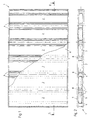
- the self-supporting panel element 1 shown in FIG. 1 is six in total rectangular segments 2 divided.
- the top and bottom ends of the panel element 1 each form frame profiles 3, which are over all six Extend segments 2 continuously.
- the frame profiles 3 are, as from FIG. 4 and 6b can be seen as a U-shaped, i.e. side members closed on three sides educated.
- the panel element 1 is divided into the individual segments 2 by structure profiles 4, which are arranged at right angles to the frame profiles 3 and attached to it.
- the structure profiles 4 each consist of Cross-section essentially U-shaped, closed on three sides, the limit the individual segments 2 laterally.
- Fig. 6a exist the structural profiles 4 each from two lateral legs 5 and one these connecting web 6.
- a core layer 7 Between the adjacent structure profiles 4, each with a leg 5 facing one another, there is a core layer 7, the thickness of the distance between the two legs 5 of a structural profile 4 corresponds.
- a particularly good heat and sound insulation with one at the same time, sufficient dimensional stability of the individual segments 2 Formed panel elements 1 is achieved in that as a material for the Core layer 7 an open-pore lightweight concrete is used.
- This lightweight concrete of the core layers 7 of the Segments 2 will depend on the purpose of the individual panel elements customized. Since the use of the panel elements 1 as building exterior wall elements, Building or apartment partition elements or Ceiling elements have different requirements for the forces to be absorbed or moments as well as the necessary thermal and acoustic insulation the density of the outer walls of the building is the lowest, since here in particular one good insulation is required. The through a particularly large pore Design of the lightweight concrete caused low density particularly good thermal insulation. The inside of a building as well particularly important when building exterior wall-to-building wall Sound insulation is due to a large mass and thus a high density of the Material of the core layer 7 reached. The density of the material of the core layer 7 of the panel elements used as ceiling elements lies between the Density of the building's outer wall elements and that of the building or Party wall elements.
- FIG. 2 are in this first embodiment the structure profiles 4 between two adjacent to each other Segments 2 with mutually facing webs 6 at a distance from one another arranged, the between the webs 6 facing each other Structural profiles 4, a support space 8 is formed.
- only panel elements used as wall elements due to normal forces 1 is the same material as the material for filling the support spaces 8 used, which is also used to form the core layer 7.
- Fig. 3 is a longitudinal section through a panel element designed as a ceiling element 1 shown. Because ceiling elements in particular on the bending stress and are therefore exposed to a moment load, the necessary dimensional stability of these panel elements 1 when using Lightweight concrete as a material for the core layer 7 can be achieved in that the support rooms 8 are filled with normal concrete, in the prestressed reinforcing iron 10 are arranged. Otherwise the structure of the as Ceiling element used panel element 1 the structure of that shown in Fig. 2 Panel element 1, which is used as a wall element.
- FIG. 6a The structure of a supporting structure profile 4 can be seen particularly clearly from FIG. 6a.
- the structure profile 4 is the formation of the structure profile 4 as a three-sided closed U-shaped profile with two legs 5 and one this leg 5 connecting web 6 can be seen.
- Fig. 4 shows schematically the design of a wall-ceiling-wall junction.
- the U-shaped profile shown in FIG. 6c serves as the connecting profile 13, whose legs 13a are curved outward and a distance from one another, which is greater than the width of the panel elements 1 along longitudinal side frame profiles 3.
- Fig. 4 takes place the connection of a ceiling element with two wall elements in that a connection profile on the opposite sides of the ceiling element 13 is arranged such that the free legs 13a of the Show away the ceiling element.
- connection profiles open upwards or downwards 13 serve to accommodate those completed with the frame profiles 3 Wall elements.
- the legs 13a form a lateral guide for the frame profiles 3 of the wall elements, the easy alignment of the Allow wall elements with respect to the ceiling element.
- For connection the wall elements with the ceiling element as well as a relative movement to prevent the frame profiles 3 to the connecting profile 13 is between the connecting profiles 13 and the frame profiles 3 a mortar layer 15 arranged.
- the right-angled connection of two designed as wall elements Panel elements are shown in Fig. 5.
- the butt faces of the right angle wall elements to be connected to one another are each by a Butt plate formed open structure 4.
- the one shown in FIG. 5 Embodiment are the free legs 5 of the open to the butt surface Structural profiles 4 shortened so that in the legs 5th formed indentations 11 only one undercut 12, namely which have undercut 12 close to web 6.
- a particularly durable one Connection of two wall elements to be connected at right angles takes place in that in addition to filling in the open by the two Structural profiles 4 formed space in the area of the joint surface with lightweight concrete the structural profiles 4 each have two connecting profiles designed as clamping profiles 14 are interconnected.
- connection profiles 14 engage the undercuts 12 of the indentations close to the web 6 11 of the adjoining legs 5 of the structure profiles 4.
- Such Design of a wall-wall connection point enables an exact right-angled connection of two wall elements and prevents mutual Moving the wall elements connected in this way.
- the design of a connecting profile 14 is particularly clear Figure 6d.
- the core layer 7 shows a second exemplary embodiment for designing a self-supporting panel element 1 shown.
- the core layer 7 is constructed in multiple layers.
- the core layer layers lying against the cover layers 9 7a made of normal concrete or lightweight concrete both core layer layers 7a not must consist of the same material, and the core layer layer 7b consists of a filler, for example an insulating material.
- the Structural profiles 4 were rotated by 90 ° so that they were open Sides of the cover layers 9 are facing.
- a composite system designed in this way for construction purposes with self-supporting Panel elements 1 thus enables simple and inexpensive Way a production of the Panel elements 1, being in addition to an adjustment to the size and function of the individual panel elements 1 also an adjustment with regard to the required mechanical stress as well as heat and noise insulation is possible.
Landscapes
- Engineering & Computer Science (AREA)
- Architecture (AREA)
- Civil Engineering (AREA)
- Structural Engineering (AREA)
- Building Environments (AREA)
- Panels For Use In Building Construction (AREA)
- Load-Bearing And Curtain Walls (AREA)
Description
- Fig. 1
- eine Ansicht eines ersten Ausführungsbeispiels eines als Wandelement ausgebildeten selbsttragenden Tafelelementes mit nur teilweise dargestellter Deckschicht;
- Fig. 2
- einen Schnitt entlang der Schnittlinie II-II in Fig. 1;
- Fig. 3
- einen Fig. 2 entsprechenden Schnitt durch ein als Deckenelement ausgelegtes selbsttragendes Tafelelement;
- Fig. 4
- eine schematische Ansicht einer Wand-Decke-Wand-Verbindungsstelle;
- Fig. 5
- eine schematische Ansicht einer rechtwinkligen Wand-Wand-Verbindungsstelle;
- Fig. 6a
- einen Querschnitt durch ein Tragwerkprofil;
- Fig. 6b
- einen Querscnitt durch ein Rahmenprofil;
- Fig. 6c
- einen Querschnitt durch ein Deckenverbindungsprofil;
- Fig. 6d
- einen Querschnitt durch ein Klemmprofil und
- Fig. 7
- einen Schnitt entsprechend Fig. 2, jedoch ein zweites Ausführungsbeispiel darstellend.
- 1
- Tafelelement
- 2
- Segment
- 3
- Rahmenprofil
- 4
- Tragwerkprofil
- 5
- Schenkel
- 6
- Steg
- 7
- Kernschicht
- 7a
- Kernschichtlage
- 7b
- Kernschichtlage
- 8
- Stützraum
- 9
- Deckschicht
- 10
- Armierungseisen
- 11
- Einformung
- 12
- Hinterschneidung
- 13
- Verbindungsprofil
- 13a
- Schenkel
- 14
- Verbindungsprofil
- 15
- Mörtelschicht
Claims (14)
- Verbundsystem für Bauzwecke mit selbsttragenden Tafelelementen, insbesondere zur Verwendung als vorgefertigte Wand- oder Deckenelemente für Gebäude, wobei die Tafelelemente (1) durchgehende U-förmige Rahmenprofile (3) aufweisen, die Tafelelemente (1) durch winklig zu den Rahmenprofilen (3) angeordnete, dreiseitig geschlossene Tragwerkprofile (4) in einzelne Segmente (2) unterteilt sind und jedes Segment (2) durch eine Kernschicht (7) gebildet ist und jedes Tafelelement (1) zumindest einseitig mit einer Deckschicht (9) versehen ist,
gekennzeichnet durch
die folgenden Merkmale:a) die Kernschicht (7) und die mindestens eine Deckschicht (9) bestehen aus einem oder mehreren dem Verwendungszweck des jeweiligen Tafelelementes (1) als Gebäudeaußenwand-, Wohnungstrennwand- oder Deckenelement bezüglich Dichte und/oder Zusammensetzung angepaßten Materialien;b) die Tragwerkprofile (4) zwischen jeweils zwei aneinandergrenzenden Segmenten (2) sind mit einander zugewandten Stegen einen Stützraum (8) bildend mit Abstand zueinander angeordnet;c) der Stützraum (8) zwischen zwei Tragwerkprofilen (4) ist mit einem Füllmaterial ausgefüllt;d) die Tragwerkprofile (4) weisen allseitig in den von den drei geschlossenen Seiten gebildeten Raum weisende, zweiseitig hinterschnittene Einformungen (11) auf unde) zwischen miteinander zu verbindenden Tafelelementen (1) sind dem jeweiligen Verwendungszweck der Tafelelemente (1) als Wand- oder Deckenelemente angepaßte Verbindungsprofile (13,14) angeordnet. - Verbundsystem nach Anspruch 1, dadurch gekennzeichnet, daß die Kernschicht (7) aus Leichtbeton besteht, wobei die Kernschicht (7) eines als Gebäudeaußenwandelement verwendeten Tafelelements (1) die geringste Dichte und die eines als Gebäude- bzw. Wohnungstrennwandelement verwendeten Tafelelements (1) die größte Dichte aufweist.
- Verbundsystem nach Anspruch 1, dadurch gekennzeichnet, daß zumindest ein Segment (2) mit einem Fenster oder einer Tür versehen ist.
- Verbundsystem nach Anspruch 1, dadurch gekennzeichnet, daß die Verbindungsprofile (13) zum Verbinden von Wandelementen und Deckenelementen als U-förmige Profile mit auswärts gebogenen Schenkeln (13a) ausgebildet sind und der Abstand der Schenkel (13a) zueinander größer ist als die Breite der die Tafelelemente (1) längsseits begrenzenden Rahmenprofile (3).
- Verbundsystem nach Anspruch 4, dadurch gekennzeichnet, daß die Deckenverbindungsprofile (13) fest mit den Deckenelementen und die Rahmenprofile (3) fest mit den Wandelementen verbunden sind.
- Verbundsystem nach Anspruch 4 oder 5, dadurch gekennzeichnet, daß zwischen den Deckenverbindungsprofilen (13) und den Rahmenprofilen (3) einer Decken-Wand-Verbindung eine Mörtelschicht (15) angeordnet ist.
- Verbundsystem nach Anspruch 1, dadurch gekennzeichnet, daß bei der Verwendung als Deckenelement die Stützräume (8) eines jeden Tafelelements (1) mit Normalbeton als Füllmaterial ausgefüllt und verspannbare Armierungseisen (10) in den Stützräumen (8) angeordnet sind.
- Verbundsystem nach Anspruch 1, dadurch gekennzeichnet, daß bei der Verwendung als Wandelement die Stützräume (8) eines jeden Tafelelements (1) mit Leichtbeton ausgefüllt sind, wobei die Dichte dieses Füllmaterials der Dichte der Materials der Kernschicht (7) entspricht.
- Verbundsystem nach Anspruch 1, dadurch gekennzeichnet, daß die Stoßflächen zweier rechtwinklig miteinander zu verbindenden Wandelemente durch jeweils ein zur Stoßfläche hin offenes Tragwerkprofil (4) gebildet sind.
- Verbundsystem nach Anspruch 9, dadurch gekennzeichnet, daß die freien Schenkel (5) der zur Stoßfläche hin offenen Tragwerkprofile (4) derart verkürzt sind, daß die in den Schenkeln (5) ausgebildeten Einformungen (11) nur die dem Steg (6) nahe Hinterschneidung (12) aufweisen.
- Verbundsystem nach Anspruch 9 oder 10, dadurch gekennzeichnet, daß die zur Stoßfläche hin offenen Tragwerkprofile (4) über jeweils zwei als Klemmprofile ausgebildete Verbindungsprofile (14) miteinander verbunden sind, von denen ein jedes die dem Steg (6) nahe Hinterschneidung (12) der Einformung (11) der aneinandergrenzenden Schenkel (5) der Tragwerkprofile (4) hintergreift.
- Verbundsystem nach einem der Ansprüche 9 bis 11, dadurch gekennzeichnet, daß der zwischen den zur Stoßfläche hin offenen Tragwerkprofilen (4) gebildete Raum mit Leichtbeton ausfüllbar ist.
- Verbundsystem nach Anspruch 1, dadurch gekennzeichnet, daß das Füllmaterial für den Stützraum (8) vorzugsweise das Material der Kernschicht (7) ist.
- Verbundsystem nach einem der Ansprüche 1 bis 13, dadurch gekennzeichnet, daß die Kernschicht (7) mehrlagig aufgebaut ist, wobei die Materialien mindestens zweier Kernschichtlagen (7a, 7b) unterschiedlich sind.
Applications Claiming Priority (2)
| Application Number | Priority Date | Filing Date | Title |
|---|---|---|---|
| DE19620296A DE19620296C1 (de) | 1996-05-21 | 1996-05-21 | Verbundsystem für Bauzwecke mit selbsttragenden Tafelelementen |
| DE19620296 | 1996-05-21 |
Publications (3)
| Publication Number | Publication Date |
|---|---|
| EP0808959A2 EP0808959A2 (de) | 1997-11-26 |
| EP0808959A3 EP0808959A3 (de) | 1999-06-09 |
| EP0808959B1 true EP0808959B1 (de) | 2003-07-30 |
Family
ID=7794810
Family Applications (1)
| Application Number | Title | Priority Date | Filing Date |
|---|---|---|---|
| EP97108084A Expired - Lifetime EP0808959B1 (de) | 1996-05-21 | 1997-05-17 | Verbundsystem für Bauzwecke mit selbsttragenden Tafelelementen |
Country Status (4)
| Country | Link |
|---|---|
| EP (1) | EP0808959B1 (de) |
| AT (1) | ATE246290T1 (de) |
| DE (2) | DE19620296C1 (de) |
| GB (1) | GB2324545A (de) |
Cited By (2)
| Publication number | Priority date | Publication date | Assignee | Title |
|---|---|---|---|---|
| DE202017101111U1 (de) | 2017-02-28 | 2017-03-11 | C.B.S. Team-Projektgesellschaft mbH | Porenbeton-Hybrid-Bauelement |
| WO2023126069A1 (de) | 2021-12-31 | 2023-07-06 | B-Ton Ip Gmbh | Verfahren zur herstellung von leichtbetonmischungen unter verwendung von leichtzuschlägen |
Families Citing this family (1)
| Publication number | Priority date | Publication date | Assignee | Title |
|---|---|---|---|---|
| HUP2100112A1 (hu) * | 2021-03-18 | 2023-08-28 | Laszlo Andrea | Térelem, valamint eljárás a térelem elõállítására |
Family Cites Families (6)
| Publication number | Priority date | Publication date | Assignee | Title |
|---|---|---|---|---|
| FR1478486A (fr) * | 1966-03-04 | 1967-04-28 | Chausson Usines Sa | Panneau de façade-rideau |
| FR1587550A (de) * | 1968-10-21 | 1970-03-20 | ||
| NL8201299A (nl) * | 1982-03-29 | 1983-10-17 | Staalframe Bv | Gebouw, wandsecties en profielen daarvoor. |
| CZ261691A3 (en) * | 1990-08-25 | 1993-10-13 | Lorenz Kesting | Section for steel framed structures |
| DE9016771U1 (de) * | 1990-12-12 | 1991-04-25 | Imhoff, Adolf, Ing.(grad.), 5860 Iserlohn | Selbsttragendes Tafelelement für Bauzwecke |
| WO1993012303A1 (en) * | 1991-12-18 | 1993-06-24 | James Hardie & Coy. Pty. Limited | Reinforced composite building panel |
-
1996
- 1996-05-21 DE DE19620296A patent/DE19620296C1/de not_active Expired - Fee Related
-
1997
- 1997-02-18 GB GB9703304A patent/GB2324545A/en not_active Withdrawn
- 1997-05-17 EP EP97108084A patent/EP0808959B1/de not_active Expired - Lifetime
- 1997-05-17 AT AT97108084T patent/ATE246290T1/de not_active IP Right Cessation
- 1997-05-17 DE DE59710490T patent/DE59710490D1/de not_active Expired - Lifetime
Cited By (3)
| Publication number | Priority date | Publication date | Assignee | Title |
|---|---|---|---|---|
| DE202017101111U1 (de) | 2017-02-28 | 2017-03-11 | C.B.S. Team-Projektgesellschaft mbH | Porenbeton-Hybrid-Bauelement |
| WO2018158211A1 (de) | 2017-02-28 | 2018-09-07 | C.B.S. Team-Projektgesellschaft mbH | Porenbeton-hybrid-bauelement |
| WO2023126069A1 (de) | 2021-12-31 | 2023-07-06 | B-Ton Ip Gmbh | Verfahren zur herstellung von leichtbetonmischungen unter verwendung von leichtzuschlägen |
Also Published As
| Publication number | Publication date |
|---|---|
| GB2324545A (en) | 1998-10-28 |
| EP0808959A3 (de) | 1999-06-09 |
| ATE246290T1 (de) | 2003-08-15 |
| GB9703304D0 (en) | 1997-04-09 |
| DE19620296C1 (de) | 1997-11-27 |
| EP0808959A2 (de) | 1997-11-26 |
| DE59710490D1 (de) | 2003-09-04 |
Similar Documents
| Publication | Publication Date | Title |
|---|---|---|
| DE3302044C3 (de) | Feuerschutz-Trennwand | |
| EP0940512B1 (de) | Plattenförmiges Brandschutzelement in Sandwich-Bauweise | |
| DE3177307T2 (de) | Rahmen zur Einfassung eines Teiles einer Wand. | |
| DE3303190C2 (de) | Bausatz zur Erstellung mobiler Bauten, insbesondere für Messe- und Ausstellungsbauten | |
| EP0551307B1 (de) | Türblatt und verfahren zur herstellung eines derartigen türblatts | |
| DE1484046A1 (de) | Gebaeudekonstruktion | |
| EP0654566B1 (de) | Brandwand mit Gipsbauplatte | |
| DE2836126A1 (de) | Anschlussbausatz fuer trennwaende und zweischalige demontierbare trennwand mit anschlusselement. | |
| EP0808959B1 (de) | Verbundsystem für Bauzwecke mit selbsttragenden Tafelelementen | |
| DE2445443A1 (de) | Wandteile fuer den bau von waenden, kammern, luftleitungen oder dergleichen von lufttechnischen anlagen | |
| DE9302447U1 (de) | Holzbautafel | |
| DE3305639C2 (de) | Feuerschutzabschluß für Bauwerksöffnungen | |
| DE3241424C2 (de) | Verbindungseinrichtung | |
| DE1484009A1 (de) | Haus in Fertigbauweise,plattenfoermiges Bauelement zur Herstellung dieses Hauses,Zwischenstueck zur Verbindung der Bauelemente und Verfahren zur Herstellung des Hauses | |
| DE3400404C2 (de) | Bauelement zur Herstellung von Gebäudeaußenwänden | |
| EP0823010A1 (de) | Vorgefertigtes wandelement für ein gebäude | |
| DE9116023U1 (de) | Plattenförmiges Bauelement, geeignet als Sichtblende, Zaunelement, Wandverkleidung u.dgl. | |
| DE2343049C3 (de) | Versetzbare Trennwand aus raumhohen Wandelementen | |
| DE3306456A1 (de) | Bauelement | |
| EP1705302A2 (de) | Element aus Backsteinmaterial zum Erstellen von vorfabrizierten Tafeln für das Bauwesen | |
| DE4443857C2 (de) | Brandwand | |
| EP0950604A2 (de) | Bauelement zur Erstellung von Wänden und/oder Decken, insbesondere auf Schiffen | |
| DE4237956A1 (en) | Shaft device providing downwardly open accommodation for roller blind, Venetian blind, or similar - has parallel drop casing shaft next to accommodation shaft which is open upwards formed by two wall elements | |
| DE29623208U1 (de) | Verbundsystem für Bauzwecke mit selbsttragenden Tafelelementen | |
| EP0128294A2 (de) | Wandelement |
Legal Events
| Date | Code | Title | Description |
|---|---|---|---|
| PUAI | Public reference made under article 153(3) epc to a published international application that has entered the european phase |
Free format text: ORIGINAL CODE: 0009012 |
|
| AK | Designated contracting states |
Kind code of ref document: A2 Designated state(s): AT BE CH DE DK ES FI FR GB GR IE IT LI LU MC NL PT SE |
|
| PUAL | Search report despatched |
Free format text: ORIGINAL CODE: 0009013 |
|
| AK | Designated contracting states |
Kind code of ref document: A3 Designated state(s): AT BE CH DE DK ES FI FR GB GR IE IT LI LU MC NL PT SE |
|
| RIC1 | Information provided on ipc code assigned before grant |
Free format text: 6E 04C 2/38 A, 6E 04C 2/04 B |
|
| 17P | Request for examination filed |
Effective date: 19990609 |
|
| GRAH | Despatch of communication of intention to grant a patent |
Free format text: ORIGINAL CODE: EPIDOS IGRA |
|
| RAP1 | Party data changed (applicant data changed or rights of an application transferred) |
Owner name: THYSSENKRUPP STAHL BAUELEMENTE GMBH |
|
| RIN1 | Information on inventor provided before grant (corrected) |
Inventor name: IMHOFF, ADOLF |
|
| GRAH | Despatch of communication of intention to grant a patent |
Free format text: ORIGINAL CODE: EPIDOS IGRA |
|
| GRAA | (expected) grant |
Free format text: ORIGINAL CODE: 0009210 |
|
| AK | Designated contracting states |
Designated state(s): AT BE CH DE DK ES FI FR GB GR IE IT LI LU MC NL PT SE |
|
| PG25 | Lapsed in a contracting state [announced via postgrant information from national office to epo] |
Ref country code: NL Free format text: LAPSE BECAUSE OF FAILURE TO SUBMIT A TRANSLATION OF THE DESCRIPTION OR TO PAY THE FEE WITHIN THE PRESCRIBED TIME-LIMIT Effective date: 20030730 Ref country code: IT Free format text: LAPSE BECAUSE OF FAILURE TO SUBMIT A TRANSLATION OF THE DESCRIPTION OR TO PAY THE FEE WITHIN THE PRE;WARNING: LAPSES OF ITALIAN PATENTS WITH EFFECTIVE DATE BEFORE 2007 MAY HAVE OCCURRED AT ANY TIME BEFORE 2007. THE CORRECT EFFECTIVE DATE MAY BE DIFFERENT FROM THE ONE RECORDED.SCRIBED TIME-LIMIT Effective date: 20030730 Ref country code: IE Free format text: LAPSE BECAUSE OF FAILURE TO SUBMIT A TRANSLATION OF THE DESCRIPTION OR TO PAY THE FEE WITHIN THE PRESCRIBED TIME-LIMIT Effective date: 20030730 Ref country code: GB Free format text: LAPSE BECAUSE OF FAILURE TO SUBMIT A TRANSLATION OF THE DESCRIPTION OR TO PAY THE FEE WITHIN THE PRESCRIBED TIME-LIMIT Effective date: 20030730 Ref country code: FR Free format text: LAPSE BECAUSE OF NON-PAYMENT OF DUE FEES Effective date: 20030730 Ref country code: FI Free format text: LAPSE BECAUSE OF FAILURE TO SUBMIT A TRANSLATION OF THE DESCRIPTION OR TO PAY THE FEE WITHIN THE PRESCRIBED TIME-LIMIT Effective date: 20030730 |
|
| REG | Reference to a national code |
Ref country code: GB Ref legal event code: FG4D Free format text: NOT ENGLISH |
|
| REG | Reference to a national code |
Ref country code: CH Ref legal event code: EP |
|
| REG | Reference to a national code |
Ref country code: IE Ref legal event code: FG4D Free format text: GERMAN |
|
| REF | Corresponds to: |
Ref document number: 59710490 Country of ref document: DE Date of ref document: 20030904 Kind code of ref document: P |
|
| PG25 | Lapsed in a contracting state [announced via postgrant information from national office to epo] |
Ref country code: SE Free format text: LAPSE BECAUSE OF FAILURE TO SUBMIT A TRANSLATION OF THE DESCRIPTION OR TO PAY THE FEE WITHIN THE PRESCRIBED TIME-LIMIT Effective date: 20031030 Ref country code: GR Free format text: LAPSE BECAUSE OF FAILURE TO SUBMIT A TRANSLATION OF THE DESCRIPTION OR TO PAY THE FEE WITHIN THE PRESCRIBED TIME-LIMIT Effective date: 20031030 Ref country code: DK Free format text: LAPSE BECAUSE OF FAILURE TO SUBMIT A TRANSLATION OF THE DESCRIPTION OR TO PAY THE FEE WITHIN THE PRESCRIBED TIME-LIMIT Effective date: 20031030 |
|
| PG25 | Lapsed in a contracting state [announced via postgrant information from national office to epo] |
Ref country code: ES Free format text: LAPSE BECAUSE OF FAILURE TO SUBMIT A TRANSLATION OF THE DESCRIPTION OR TO PAY THE FEE WITHIN THE PRESCRIBED TIME-LIMIT Effective date: 20031110 |
|
| NLV1 | Nl: lapsed or annulled due to failure to fulfill the requirements of art. 29p and 29m of the patents act | ||
| PG25 | Lapsed in a contracting state [announced via postgrant information from national office to epo] |
Ref country code: PT Free format text: LAPSE BECAUSE OF FAILURE TO SUBMIT A TRANSLATION OF THE DESCRIPTION OR TO PAY THE FEE WITHIN THE PRESCRIBED TIME-LIMIT Effective date: 20031230 |
|
| GBV | Gb: ep patent (uk) treated as always having been void in accordance with gb section 77(7)/1977 [no translation filed] |
Effective date: 20030730 |
|
| REG | Reference to a national code |
Ref country code: IE Ref legal event code: FD4D |
|
| PG25 | Lapsed in a contracting state [announced via postgrant information from national office to epo] |
Ref country code: LU Free format text: LAPSE BECAUSE OF NON-PAYMENT OF DUE FEES Effective date: 20040517 |
|
| PGFP | Annual fee paid to national office [announced via postgrant information from national office to epo] |
Ref country code: AT Payment date: 20040526 Year of fee payment: 8 |
|
| PG25 | Lapsed in a contracting state [announced via postgrant information from national office to epo] |
Ref country code: MC Free format text: LAPSE BECAUSE OF NON-PAYMENT OF DUE FEES Effective date: 20040531 Ref country code: BE Free format text: LAPSE BECAUSE OF NON-PAYMENT OF DUE FEES Effective date: 20040531 |
|
| PLBE | No opposition filed within time limit |
Free format text: ORIGINAL CODE: 0009261 |
|
| STAA | Information on the status of an ep patent application or granted ep patent |
Free format text: STATUS: NO OPPOSITION FILED WITHIN TIME LIMIT |
|
| PGFP | Annual fee paid to national office [announced via postgrant information from national office to epo] |
Ref country code: CH Payment date: 20040623 Year of fee payment: 8 |
|
| 26N | No opposition filed |
Effective date: 20040504 |
|
| EN | Fr: translation not filed | ||
| BERE | Be: lapsed |
Owner name: *THYSSENKRUPP STAHL BAUELEMENTE G.M.B.H. Effective date: 20040531 |
|
| PG25 | Lapsed in a contracting state [announced via postgrant information from national office to epo] |
Ref country code: AT Free format text: LAPSE BECAUSE OF NON-PAYMENT OF DUE FEES Effective date: 20050517 |
|
| PG25 | Lapsed in a contracting state [announced via postgrant information from national office to epo] |
Ref country code: LI Free format text: LAPSE BECAUSE OF NON-PAYMENT OF DUE FEES Effective date: 20050531 Ref country code: CH Free format text: LAPSE BECAUSE OF NON-PAYMENT OF DUE FEES Effective date: 20050531 |
|
| REG | Reference to a national code |
Ref country code: CH Ref legal event code: PL |
|
| REG | Reference to a national code |
Ref country code: DE Ref legal event code: R082 Ref document number: 59710490 Country of ref document: DE Representative=s name: HAVERKAMP, JENS, PROF. DIPL.-GEOL. DR.RER.NAT., DE Effective date: 20140227 Ref country code: DE Ref legal event code: R082 Ref document number: 59710490 Country of ref document: DE Representative=s name: HAVERKAMP, JENS, PROF. DIPL.-GEOL. DR.RER.NAT., DE Effective date: 20140306 Ref country code: DE Ref legal event code: R081 Ref document number: 59710490 Country of ref document: DE Owner name: SABBAH, ANTOINE, SA Free format text: FORMER OWNERS: IMHOFF, DELIA, 58642 ISERLOHN, DE; IMHOFF, KRISTINA, 58642 ISERLOHN, DE; IMHOFF, TOBIAS, 58642 ISERLOHN, DE Effective date: 20140227 Ref country code: DE Ref legal event code: R081 Ref document number: 59710490 Country of ref document: DE Owner name: IMHOFF, KRISTINA, DE Free format text: FORMER OWNERS: SABBAH, ANTOINE, JEDDAH, SA; SAM-SIN, ROBERT JOHN, PARAMARIBO, SR Effective date: 20140306 Ref country code: DE Ref legal event code: R081 Ref document number: 59710490 Country of ref document: DE Owner name: IMHOFF, TOBIAS, DE Free format text: FORMER OWNERS: SABBAH, ANTOINE, JEDDAH, SA; SAM-SIN, ROBERT JOHN, PARAMARIBO, SR Effective date: 20140306 Ref country code: DE Ref legal event code: R081 Ref document number: 59710490 Country of ref document: DE Owner name: IMHOFF, KRISTINA, DE Free format text: FORMER OWNERS: IMHOFF, DELIA, 58642 ISERLOHN, DE; IMHOFF, KRISTINA, 58642 ISERLOHN, DE; IMHOFF, TOBIAS, 58642 ISERLOHN, DE Effective date: 20140227 Ref country code: DE Ref legal event code: R081 Ref document number: 59710490 Country of ref document: DE Owner name: IMHOFF, DELIA, DE Free format text: FORMER OWNERS: SABBAH, ANTOINE, JEDDAH, SA; SAM-SIN, ROBERT JOHN, PARAMARIBO, SR Effective date: 20140306 Ref country code: DE Ref legal event code: R081 Ref document number: 59710490 Country of ref document: DE Owner name: SAM-SIN, ROBERT JOHN, SR Free format text: FORMER OWNERS: SABBAH, ANTOINE, JEDDAH, SA; SAM-SIN, ROBERT JOHN, PARAMARIBO, SR Effective date: 20140306 Ref country code: DE Ref legal event code: R081 Ref document number: 59710490 Country of ref document: DE Owner name: IMHOFF, TOBIAS, DE Free format text: FORMER OWNERS: IMHOFF, DELIA, 58642 ISERLOHN, DE; IMHOFF, KRISTINA, 58642 ISERLOHN, DE; IMHOFF, TOBIAS, 58642 ISERLOHN, DE Effective date: 20140227 Ref country code: DE Ref legal event code: R081 Ref document number: 59710490 Country of ref document: DE Owner name: IMHOFF, DELIA, DE Free format text: FORMER OWNERS: IMHOFF, DELIA, 58642 ISERLOHN, DE; IMHOFF, KRISTINA, 58642 ISERLOHN, DE; IMHOFF, TOBIAS, 58642 ISERLOHN, DE Effective date: 20140227 Ref country code: DE Ref legal event code: R081 Ref document number: 59710490 Country of ref document: DE Owner name: SABBAH, ANTOINE, SA Free format text: FORMER OWNERS: SABBAH, ANTOINE, JEDDAH, SA; SAM-SIN, ROBERT JOHN, PARAMARIBO, SR Effective date: 20140306 Ref country code: DE Ref legal event code: R081 Ref document number: 59710490 Country of ref document: DE Owner name: SAM-SIN, ROBERT JOHN, SR Free format text: FORMER OWNERS: IMHOFF, DELIA, 58642 ISERLOHN, DE; IMHOFF, KRISTINA, 58642 ISERLOHN, DE; IMHOFF, TOBIAS, 58642 ISERLOHN, DE Effective date: 20140227 Ref country code: DE Ref legal event code: R081 Ref document number: 59710490 Country of ref document: DE Owner name: IMHOFF, TOBIAS, DE Free format text: FORMER OWNER: DELIA IMHOFF,KRISTINA IMHOFF,TOBIAS IMHOFF, , DE Effective date: 20140227 Ref country code: DE Ref legal event code: R081 Ref document number: 59710490 Country of ref document: DE Owner name: IMHOFF, DELIA, DE Free format text: FORMER OWNER: DELIA IMHOFF,KRISTINA IMHOFF,TOBIAS IMHOFF, , DE Effective date: 20140227 Ref country code: DE Ref legal event code: R081 Ref document number: 59710490 Country of ref document: DE Owner name: IMHOFF, KRISTINA, DE Free format text: FORMER OWNER: ANTOINE SABBAH,ROBERT JOHN SAM-SIN, , SR Effective date: 20140306 Ref country code: DE Ref legal event code: R081 Ref document number: 59710490 Country of ref document: DE Owner name: IMHOFF, TOBIAS, DE Free format text: FORMER OWNER: ANTOINE SABBAH,ROBERT JOHN SAM-SIN, , SR Effective date: 20140306 Ref country code: DE Ref legal event code: R081 Ref document number: 59710490 Country of ref document: DE Owner name: SABBAH, ANTOINE, SA Free format text: FORMER OWNER: DELIA IMHOFF,KRISTINA IMHOFF,TOBIAS IMHOFF, , DE Effective date: 20140227 Ref country code: DE Ref legal event code: R081 Ref document number: 59710490 Country of ref document: DE Owner name: IMHOFF, DELIA, DE Free format text: FORMER OWNER: ANTOINE SABBAH,ROBERT JOHN SAM-SIN, , SR Effective date: 20140306 Ref country code: DE Ref legal event code: R081 Ref document number: 59710490 Country of ref document: DE Owner name: IMHOFF, KRISTINA, DE Free format text: FORMER OWNER: DELIA IMHOFF,KRISTINA IMHOFF,TOBIAS IMHOFF, , DE Effective date: 20140227 Ref country code: DE Ref legal event code: R081 Ref document number: 59710490 Country of ref document: DE Owner name: SAM-SIN, ROBERT JOHN, SR Free format text: FORMER OWNER: DELIA IMHOFF,KRISTINA IMHOFF,TOBIAS IMHOFF, , DE Effective date: 20140227 Ref country code: DE Ref legal event code: R081 Ref document number: 59710490 Country of ref document: DE Owner name: SABBAH, ANTOINE, SA Free format text: FORMER OWNER: ANTOINE SABBAH,ROBERT JOHN SAM-SIN, , SR Effective date: 20140306 Ref country code: DE Ref legal event code: R081 Ref document number: 59710490 Country of ref document: DE Owner name: SAM-SIN, ROBERT JOHN, SR Free format text: FORMER OWNER: ANTOINE SABBAH,ROBERT JOHN SAM-SIN, , SR Effective date: 20140306 |
|
| PGFP | Annual fee paid to national office [announced via postgrant information from national office to epo] |
Ref country code: DE Payment date: 20161121 Year of fee payment: 20 |
|
| REG | Reference to a national code |
Ref country code: DE Ref legal event code: R071 Ref document number: 59710490 Country of ref document: DE |