EP0808959A2 - Verbundsystem für Bauzwecke mit selbsttragenden Tafelelementen - Google Patents
Verbundsystem für Bauzwecke mit selbsttragenden Tafelelementen Download PDFInfo
- Publication number
- EP0808959A2 EP0808959A2 EP97108084A EP97108084A EP0808959A2 EP 0808959 A2 EP0808959 A2 EP 0808959A2 EP 97108084 A EP97108084 A EP 97108084A EP 97108084 A EP97108084 A EP 97108084A EP 0808959 A2 EP0808959 A2 EP 0808959A2
- Authority
- EP
- European Patent Office
- Prior art keywords
- profiles
- elements
- composite system
- wall
- panel
- Prior art date
- Legal status (The legal status is an assumption and is not a legal conclusion. Google has not performed a legal analysis and makes no representation as to the accuracy of the status listed.)
- Granted
Links
Images

Classifications
-
- E—FIXED CONSTRUCTIONS
- E04—BUILDING
- E04C—STRUCTURAL ELEMENTS; BUILDING MATERIALS
- E04C2/00—Building elements of relatively thin form for the construction of parts of buildings, e.g. sheet materials, slabs, or panels
- E04C2/30—Building elements of relatively thin form for the construction of parts of buildings, e.g. sheet materials, slabs, or panels characterised by the shape or structure
- E04C2/38—Building elements of relatively thin form for the construction of parts of buildings, e.g. sheet materials, slabs, or panels characterised by the shape or structure with attached ribs, flanges, or the like, e.g. framed panels
- E04C2/384—Building elements of relatively thin form for the construction of parts of buildings, e.g. sheet materials, slabs, or panels characterised by the shape or structure with attached ribs, flanges, or the like, e.g. framed panels with a metal frame
-
- E—FIXED CONSTRUCTIONS
- E04—BUILDING
- E04C—STRUCTURAL ELEMENTS; BUILDING MATERIALS
- E04C2/00—Building elements of relatively thin form for the construction of parts of buildings, e.g. sheet materials, slabs, or panels
- E04C2/02—Building elements of relatively thin form for the construction of parts of buildings, e.g. sheet materials, slabs, or panels characterised by specified materials
- E04C2/04—Building elements of relatively thin form for the construction of parts of buildings, e.g. sheet materials, slabs, or panels characterised by specified materials of concrete or other stone-like material; of asbestos cement; of cement and other mineral fibres
- E04C2/049—Building elements of relatively thin form for the construction of parts of buildings, e.g. sheet materials, slabs, or panels characterised by specified materials of concrete or other stone-like material; of asbestos cement; of cement and other mineral fibres completely or partially of insulating material, e.g. cellular concrete or foamed plaster
Definitions
- the invention relates to a composite system for construction purposes with self-supporting panel elements, in particular for use as prefabricated wall or ceiling elements for buildings, the panel elements having continuous, U-shaped frame profiles, dividing the panel elements into individual segments by three-sided closed structure profiles arranged at an angle to the frame profiles are and each segment is formed by a core layer and each panel element is provided at least on one side with a cover layer.
- the invention has for its object to provide a composite system for building with self-supporting panel elements which can produce easily and inexpensively also in small series and individual design in terms of building requirements.
- a composite system constructed in this way with self-supporting panel elements can be produced in a simple manner in terms of size and function, adapted to the respective requirements. It is therefore particularly suitable for the production of small series and for an individual construction.
- the individual adaptation of the density and / or composition of the core layer of the panel elements depending on the intended use of these panel elements as a building exterior wall, building or apartment partition wall or ceiling element is particularly advantageous in terms of price.
- Another, cost-reducing advantage is that special connecting profiles are provided in the composite system according to the invention, which enable a simple and quick connection of the individual panel elements to one another.
- the subdivision of the panel elements into a number of segments, each subdivided by structural profiles, results in a structure that is in the form of a structure or a framework, which can be adapted to different requirements by appropriate selection of the number and size of the segments.
- the individual segments within a panel element can serve different functions.
- the segments normally fulfill their primary task as wall or ceiling parts.
- the core layer of the segments consists of lightweight concrete, the core layer of a panel element used as an outer wall element of the building having the lowest density and that of a panel element used as a partition wall element having the greatest density.
- any openings for doors, windows and the like can be arranged in the segments.
- the connecting profiles for connecting wall elements and ceiling elements are designed as U-shaped profiles with legs bent outwards, the distance between the legs being greater than the width of the frame profiles delimiting the panel elements along the side.
- a layer of mortar is arranged between the ceiling connection profile and the frame profile of a ceiling-wall connection. This layer of mortar ensures that the frame profile of the wall element and the ceiling connection profile of the ceiling element cannot move relative to one another.
- the support spaces of each panel element can be filled with normal concrete as filler material and prestressable reinforcing bars can be arranged in the support spaces.
- the abutting surfaces of two wall elements to be connected at right angles to one another are each formed by a support profile that is open toward the abutting surface.
- the free legs of the supporting structure profiles which are open towards the abutting surface are shortened in such a way that the indentations formed in the legs only have the undercut close to the web.
- the structure profiles open towards the butt surface can be connected to one another via two clamping profiles, each of which has the undercuts close to the web the recesses of the adjoining legs of the structural profiles.
- the space delimited in the region of the butt surface by the facing open structural profiles and the clamping profiles connecting the structural profiles to one another can be filled with the material that corresponds to the material of the core layer.
- the core layer be constructed in multiple layers, the materials of at least two core layer layers being different.
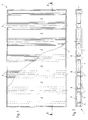
- the self-supporting panel element 1 shown in FIG. 1 is divided into a total of six rectangular segments 2.
- the upper and the lower end of the panel element 1 each form frame profiles 3 which extend continuously over all six segments 2.
- the frame profiles 3 are U-shaped, i.e. closed side members formed on three sides.
- the subdivision of the panel element 1 into the individual segments 2 is carried out by supporting structure profiles 4, which are arranged at right angles to the frame profiles 3 and fastened to them.
- the structure profiles 4 each consist of cross-sections which are essentially U-shaped and closed on three sides and which laterally delimit the individual segments 2.
- the structural profiles 4 each consist of two lateral legs 5 and a web 6 connecting them. Between the adjacent structural profiles 4 with mutually facing legs 5 there is a core layer 7, the thickness of which is the distance between the two legs 5 of a structural profile 4 corresponds.
- a particularly good heat and sound insulation with at the same time sufficient dimensional stability of the panel elements 1 formed from the individual segments 2 is achieved in that an open-pore lightweight concrete is used as the material for the core layer 7.
- the density and / or composition of this lightweight concrete of the core layers 7 of the segments 2 is adapted to the intended use of the individual panel elements. Since the use of the panel elements 1 as building exterior wall elements, building or apartment partition wall elements or ceiling elements places various demands on the forces or moments to be absorbed as well as the necessary thermal and acoustic insulation, the density of the building exterior walls is the lowest, since good thermal insulation is particularly required here.
- the low density caused by a particularly large-pored design of the lightweight concrete constitutes one particularly good thermal insulation.
- the sound insulation that is particularly important in the interior of a building and in the building outer wall-to-building outer wall is achieved by a large mass and thus a high density of the material of the core layer 7.
- the density of the material of the core layer 7 of the panel elements used as ceiling elements lies between the density of the building exterior wall elements and that of the building or apartment partition elements.
- the supporting structure profiles 4 are arranged at a distance from one another between two adjacent segments 2 with mutually facing webs 6, a support space 8 being formed between the facing webs 6 of the supporting structure profiles 4.
- the same material is used as the material for filling the support spaces 8, which material is also used to form the core layer 7.
- the panel element 1 is provided on both sides with a cover layer 9 which, in addition to fire protection, can have a further insulating effect.
- FIG. 3 shows a longitudinal section through a panel element 1 designed as a ceiling element. Since ceiling elements are particularly exposed to the bending stress and thus a moment load, the necessary dimensional stability of these panel elements 1 when using lightweight concrete as the material for the core layer 7 can be achieved in that the support spaces 8 are filled with normal concrete, arranged in the prestressed reinforcing iron 10 are. Otherwise, the structure of the panel element 1 used as a ceiling element corresponds to the structure of the panel element 1 shown in FIG. 2, which is used as a wall element.
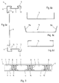
- FIG. 6a The structure of a supporting structure profile 4 can be seen particularly clearly from FIG. 6a.
- This figure shows in particular the design of the structure profile 4 as a U-shaped profile closed on three sides with two legs 5 and a web 6 connecting these legs 5.
- the structure profile 4 has on the legs 5 and the web 6 in those formed by the three sides Space-shaped recesses 11 which are dovetail-shaped on both sides with undercuts 12.
- Fig. 4 shows schematically the design of a wall-ceiling-wall connection point.
- the U-shaped profile shown in FIG. 6c is used as the connecting profile 13, the legs 13a of which are curved outwards and are at a distance from one another which is greater than the width of the frame profiles 3 delimiting the panel elements 1 on the longitudinal side.
- the connection of a ceiling element with two wall elements takes place in that a connection profile 13 is arranged on the opposite sides of the ceiling element in such a way that the free legs 13a point away from the ceiling element.
- the upward and downward open connection profiles 13 serve to accommodate the wall elements closed with the frame profiles 3.
- the legs 13a form a lateral guide for the frame profiles 3 of the wall elements, which allow easy alignment of the wall elements with respect to the ceiling element.
- a mortar layer 15 is arranged between the connection profiles 13 and the frame profiles 3.
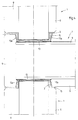
- the right-angled connection of two panel elements designed as wall elements is shown in FIG. 5.
- the abutting surfaces of the wall elements to be connected at right angles to one another are each formed by a supporting structure profile 4 that is open toward the abutting surface.
- the free legs 5 of the supporting structure profiles 4, which are open towards the butt surface are shortened in such a way that the indentations 11 formed in the legs 5 only have an undercut 12, namely the undercut 12 close to the web 6.
- a particularly durable connection of two wall elements to be connected at right angles is achieved in that, in addition to filling the space formed by the two open structural profiles 4 in the area of the abutting surface with lightweight concrete, the structural profiles 4 each have two connecting profiles designed as clamping profiles 14 are connected.
- connection profiles 14 engage behind the undercuts 12 of the recesses 11 of the adjoining legs 5 of the supporting structure profiles 4, which are close to the web 6.
- Such a configuration of a wall-wall connection point enables an exact right-angled connection of two wall elements and prevents mutual displacement of the wall elements connected in this way.
- the configuration of a connecting profile 14 can be seen particularly clearly in the illustration in FIG. 6d.
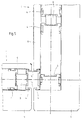
- the core layer 7 shows a second exemplary embodiment for the configuration of a self-supporting panel element 1.
- a comparison with the sectional view according to FIG. 2 shows that in this second embodiment the core layer 7 is constructed in several layers.
- the core layer layers 7a lying against the cover layers 9 consist of normal concrete or lightweight concrete, wherein both core layer layers 7a do not have to consist of the same material, and the core layer layer 7b consists of a filler, for example an insulating material.
- the structural profiles 4 have been rotated through 90 ° in such a way that their open sides face the cover layers 9.
- Such a composite system for construction purposes with self-supporting panel elements 1 thus enables production of panel elements 1 that is adapted to the respective purposes in a simple and cost-effective manner, whereby in addition to an adaptation to the size and function of the individual panel elements 1, an adjustment with regard to the required mechanical load and Thermal and noise insulation is possible.
Landscapes
- Engineering & Computer Science (AREA)
- Architecture (AREA)
- Civil Engineering (AREA)
- Structural Engineering (AREA)
- Building Environments (AREA)
- Panels For Use In Building Construction (AREA)
- Load-Bearing And Curtain Walls (AREA)
Abstract
- a) Die Kernschicht (7) und die mindestens eine Deckschicht (9) bestehen aus einem oder mehreren dem Verwendungszweck des jeweiligen Tafelelementes (1) als Gebäudeaußenwand-, Wohnungstrennwand- oder Deckenelement bezüglich Dichte und/oder Zusammensetzung angepaßten Materialien;
- b) die Tragwerkprofile (4) zwischen jeweils zwei aneinandergrenzenden Segmenten (2) sind mit einander zugewandten Stegen (6) einen Stützraum bildend mit Abstand zueinander angeordnet;
- c) der Stützraum (8) zwischen zwei Tragwerkprofilen (4) ist mit einem Füllmaterial ausgefüllt;
- d) die Tragwerkprofile (4) weisen allseitig in den von den drei geschlossenen Seiten gebildeten Raum weisende, zweiseitig hinterschnittene Einformungen (11) auf und
- e) zwischen miteinander zu verbindenden Tafelelementen (1) sind dem jeweiligen Verwendungszweck der Tafelelemente (1) als Wand- oder Deckenelemente angepaßte Verbindungsprofile (13,14) angeordnet.
Description
- Die Erfindung betrifft ein Verbundsystem für Bauzwecke mit selbsttragenden Tafelelementen, insbesondere zur Verwendung als vorgefertigte Wand- oder Deckenelemente für Gebäude, wobei die Tafelelemente durchgehende, U-förmige Rahmenprofile aufweisen, die Tafelelemente durch winklig zu den Rahmenprofilen angeordnete, dreiseitig geschlossene Tragwerkprofile in einzelne Segmente unterteilt sind und jedes Segment durch eine Kernschicht gebildet ist sowie jedes Tafelelement zumindest einseitig mit einer Deckschicht versehen ist.
- Es ist bekannt, zur Schnellerrichtung von Gebäuden ganze Wände und Decken als Fertigteile zu verarbeiten. Bei der Herstellung derartiger Fertigteile im Werk werden diese entsprechend den durch die Gebäudearchitektur festgelegten Vorgaben produziert. Auch die Zusatzfunktionen betreffenden Maßnahmen wie der Einbau von Tür- und Fensteröffnungen werden bereits im Werk durchgeführt. In größeren Serien lassen sich derartige Elemente preisgünstig herstellen, jedoch erfordern Anpassungen hinsichtlich Größe und Funktion des jeweiligen Elementes relativ aufwendige Änderungen im Herstellungsprozeß.
- Aus dem DE-GM 90 16 771.6 ist ein selbsttragendes Tafelelement der eingangs genannten Art bekannt. Diese solchermaßen hergestellten selbsttragenden Tafelelemente lassen sich zwar auf einfache Weise hinsichtlich Größe und Funktion an den jeweiligen Verwendungszweck anpassen, jedoch hat sich in der Praxis herausgestellt, daß die solchermaßen hergestellten Tafelelemente für den jeweiligen Verwendungszweck als Wand- oder Deckenelement nicht optimal ausgelegt sind, da die alle identisch hergestellten Tafelelemente bei diesem bekannten Bausystem so ausgelegt sein müssen, daß sie die bei Gebäudewänden auftretenden Normalkräfte sowie die bei Decken auftretenden Biegemomente aufnehmen können. Somit sind diese Tafelelemente je nach Verwendungszweck als Wand- oder Deckenelement jeweils bezüglich einer Kraft- bzw. Momentenkomponente überdimensioniert. Darüber hinaus hat sich herausgestellt, daß die Verbindung der einzelnen Tafelelemente untereinander sehr zeitaufwendig und somit kostenintensiv ist, da an den einzelnen Stoß- oder Auflageflächen Bolzenverbindungen notwendig sind.
- Der Erfindung liegt die Aufgabe zugrunde, ein Verbundsystem für Bauzwecke mit selbsttragenden Tafelelementen zu schaffen, welches sich auch in kleinen Serien und bei individueller Bauweise hinsichtlich der bautechnischen Anforderungen einfach und kostengünstig produzieren läßt.
- Die Lösung dieser Aufgabenstellung ist durch die folgenden Merkmale gekennzeichnet:
- a) Die Kernschicht und die mindestens eine Deckschicht bestehen aus einem oder mehreren dem Verwendungszweck des jeweiligen Tafelelementes als Gebäudeaußenwand-, Wohnungstrennwand- oder Deckenelement bezüglich Dichte und/oder Zusammensetzung angepaßten Materialien;
- b) die Tragwerkprofile zwischen jeweils zwei aneinandergrenzenden Segmenten sind mit einander zugewandten Stegen einen Stützraum bildend mit Abstand zueinander angeordnet;
- c) der Stützraum zwischen zwei Tragwerkprofilen ist mit einem Füllmaterial ausgefüllt;
- d) die Tragwerkprofile weisen allseitig in den von den drei geschlossenen Seiten gebildeten Raum weisende, zweiseitig hinterschnittene Einformungen auf und
- e) zwischen miteinander zu verbindenden Tafelelementen sind dem jeweiligen Verwendungszweck der Tafelelemente als Wand- oder Deckenelemente angepaßte Verbindungsprofile angeordnet.
- Ein nach dieser Weise aufgebautes Verbundsystem mit selbsttragenden Tafelelementen läßt sich auf einfache Weise hinsichtlich Größe und Funktion den jeweiligen Anforderungen angepaßt produzieren. Es ist daher insbesondere zur Herstellung kleiner Serien und für eine individuelle Bauweise geeignet. Preislich vorteilhaft ist dabei insbesondere die individuelle Anpassung der Dichte und/oder Zusammensetzung der Kernschicht der Tafelelemente in Abhängigkeit von dem Verwendungszweck dieser Tafelelemente als Gebäudeaußenwand-, Gebäude- bzw. Wohnungstrennwand- oder Deckenelement. Ein weiterer, die Kosten senkender Vorteil besteht darin, daß bei dem erfindungsgemäßen Verbundsystem spezielle Verbindungsprofile vorgesehen sind, die eine einfache und schnelle Verbindung der einzelnen Tafelelemente untereinander ermöglichen.
- Durch die Unterteilung der Tafelelemente in mehrere, jeweils durch Tragwerkprofile unterteilte Segmente ergibt sich insgesamt eine trag- oder ständerwerkartige Konstruktion, die durch entsprechende Wahl der Zahl und Größe der Segmente unterschiedlichen Anforderungen angepaßt werden kann. Innerhalb eines Tafelelementes können die einzelnen Segmente unterschiedlichen Funktionen dienen. Im Normalfall erfüllen die Segmente Ihre primäre Aufgabe als Wand- bzw. Deckenteile. In diesem Fall besteht die Kernschicht der Segmente aus Leichtbeton, wobei die Kernschicht eines als Gebäudeaußenwandelement verwendeten Tafelelements die geringste Dichte und die eines als Wohnungstrennwandelement verwendeten Tafelelements die größte Dichte aufweist. Ebenso können in den Segmenten beliebige Öffnungen für Türen, Fenster und dergleichen angeordnet werden.
- Gemäß einer bevorzugten Ausführungsform der Erfindung sind die Verbindungsprofile zum Verbinden von Wandelementen und Deckenelementen als U-förmige Profile mit auswärts gebogenen Schenkeln ausgebildet, wobei der Abstand der Schenkel zueinander größer ist als die Breite der die Tafelelemente längsseits begrenzenden Rahmenprofile. Durch das feste Anordnen dieser Deckenverbindungsprofile mit den Deckenelementen sowie das feste Anordnen der Rahmenprofile mit den Wandelementen ist eine einfache und sichere Verbindung von Deckenelement und Wandelement dadurch möglich, daß das mit dem Deckenelement verbundene Deckenverbindungsprofil das Rahmenprofil eines Wandelementes übergreifend auf ein Wandelement aufgelegt und/oder ein Wandelement mit seinem das Wandelement nach unten abschließenden Rahmenprofil in ein solches U-förmiges Deckenprofil hereingestellt wird.
- Um einen sicheren und dauerhaften Halt zwischen dem jeweiligen Deckenverbindungsprofil und dem darin aufgenommenen Rahmenprofil eines Wandelementes zu gewährleisten, ist zwischen dem Deckenverbindungsprofil und dem Rahmenprofil einer Decken-Wand-Verbindung eine Mörtelschicht angeordnet. Durch diese Mörtelschicht wird gewährleistet, daß das Rahmenprofil des Wandelementes und das Deckenverbindungsprofil des Deckenelementes sich nicht relativ zueinander verschieben können.
- Um die als Deckenelement verwendeten Tafelelemente an die Aufnahme der auftretenden Biegemomente anzupassen, können die Stützräume eines jeden Tafelelementes mit Normalbeton als Füllmaterial ausgefüllt und vorspannbare Armierungseisen in den Stützräumen angeordnet werden.
- Dahingegen ist es bei der Verwendung der Tafelelemente als Wandelemente ausreichend, die Stützräume eines jeden Tafelelements mit dem hinsichtlich Dichte und Zusammensetzung identischen Material zu verfüllen, aus dem auch die Kernschicht gebildet ist.
- Weiterhin wird mit der Erfindung vorgeschlagen, daß die Stoßflächen zweier rechtwinklig miteinander zu verbindenden Wandelemente durch jeweils ein zur Stoßfläche hin offenes Tragwerkprofil gebildet sind. Gemäß einer bevorzugten Ausführungsform sind die freien Schenkel der zur Stoßfläche hin offenen Tragwerkprofile derart verkürzt, daß die in den Schenkeln ausgebildeten Einformungen nur die dem Steg nahe Hinterschneidung aufweisen.
- Zur rechtwinkligen Verbindung zweier Wandelemente wird vorgeschlagen, daß die zur Stoßfläche hin offenen Tragwerkprofile über jeweils zwei Klemmprofile miteinander verbindbar sind, von denen ein jedes die dem Steg nahen Hinterschneidungen der Einformungen der aneinander angrenzenden Schenkel der Tragwerkprofile hintergreift.
- Schließlich wird mit der Erfindung vorgeschlagen, daß der im Bereich der Stoßfläche durch die einander zugewandten offenen Tragwerkprofile sowie die die Tragwerkprofile miteinander verbindenden Klemmprofile umgrenzte Raum mit dem Material ausfüllbar ist, das dem Material der Kernschicht entspricht.
- Gemäß einer weiteren Ausführungsform der Erfindung wird vorgeschlagen, daß die Kernschicht mehrlagig aufgebaut ist, wobei die Materialien mindestens zweier Kernschichtlagen unterschiedlich sind.
- Weitere Einzelheiten und Vorteile der Erfindung ergeben sich aus der nachfolgenden Beschreibung der zugehörigen Zeichnung, in der zwei Ausführungsbeispiele eines erfindungsgemäßen Verbindungssystems für Bauzwecke mit selbsttragenden Tafelelementen dargestellt sind. In der Zeichnung zeigt:
- Fig. 1
- eine Ansicht eines ersten Ausführungsbeispiels eines als Wandelement ausgebildeten selbsttragenden Tafelelementes mit nur teilweise dargestellter Deckschicht;
- Fig. 2
- einen Schnitt entlang der Schnittlinie II-II in Fig. 1;
- Fig. 3
- einen Fig. 2 entsprechenden Schnitt durch ein als Deckenelement ausgelegtes selbsttragendes Tafelelement;
- Fig. 4
- eine schematische Ansicht einer Wand-Decke-Wand-Verbindungsstelle;
- Fig. 5
- eine schematische Ansicht einer rechtwinkligen Wand-Wand-Verbindungsstelle;
- Fig. 6a
- einen Querschnitt durch ein Tragwerkprofil;
- Fig. 6b
- einen Querscnitt durch ein Rahmenprofil;
- Fig. 6c
- einen Querschnitt durch ein Deckenverbindungsprofil;
- Fig. 6d
- einen Querschnitt durch ein Klemmprofil und
- Fig. 7
- einen Schnitt entsprechend Fig. 2, jedoch ein zweites Ausführungsbeispiel darstellend.
- Das in Fig. 1 dargestellte selbsttragende Tafelelement 1 ist in insgesamt sechs rechteckige Segmente 2 unterteilt. Den oberen sowie den unteren Abschluß des Tafelelementes 1 bilden jeweils Rahmenprofile 3, die sich über alle sechs Segmente 2 durchgehend erstrecken. Die Rahmenprofile 3 sind, wie aus Fig. 4 und 6b ersichtlich, als U-förmige, d.h. an drei Seiten geschlossene Längsträger ausgebildet.
- Die Unterteilung des Tafelelements 1 in die einzelnen Segmente 2 erfolgt durch Tragwerkprofile 4, die rechtwinklig zu den Rahmenprofilen 3 angeordnet und an diesen befestigt sind. Die Tragwerkprofile 4 bestehen jeweils aus im Querschnitt im wesentlichen U-förmigen, dreiseitig geschlossenen Profilen, die die einzelnen Segmente 2 seitlich begrenzen. Wie aus Fig. 6a ersichtlich, bestehen die Tragwerkprofile 4 jeweils aus zwei seitlichen Schenkeln 5 und einem diese verbindenden Steg 6. Zwischen den benachbarten Tragwerkprofilen 4 mit einander zugewandten Schenkeln 5 befindet sich jeweils eine Kernschicht 7, deren Dicke dem Abstand beider Schenkel 5 eines Tragwerkprofils 4 entspricht. Eine besonders gute Wärme- und Schalldämmung bei einer gleichzeitig ausreichenden Formstabilität der aus den einzelnen Segmenten 2 gebildeten Tafelelemente 1 wird dadurch erreicht, daß als Material für die Kernschicht 7 ein offenporiger Leichtbeton verwendet wird. Die Dichte und/oder Zusammensetzung dieses Leichtbetons der Kernschichten 7 der Segmente 2 wird dabei an den Verwendungszweck der einzelnen Tafelelemente angepaßt. Da die Verwendung der Tafelelemente 1 als Gebäudeaußenwandelemente, Gebäude- bzw. Wohnungstrennwandelemente oder Deckenelemente verschiedene Anforderungen an die aufzunehmenden Kräfte oder Momente sowie die notwendige Wärme- und Schalldämmung stellt, ist die Dichte der Gebäudeaußenwände am geringsten, da hier insbesondere eine gute Wärmedämmung erforderlich ist. Die durch eine besonders großporige Ausgestaltung des Leichtbetons hervorgerufene geringe Dichte stellt eine besonders gute Wärmedämmung dar. Die im Inneren eines Gebäudes sowie beim Bauen Gebäudeaußenwand-an-Gebäudeaußenwand besonders wichtige Schalldämmung wird durch eine große Masse und somit eine hohe Dichte des Materials der Kernschicht 7 erreicht. Die Dichte des Materials der Kernschicht 7 der als Deckenelemente verwendeten Tafelelemente liegt zwischen der Dichte der Gebäudeaußenwandelemente und der der Gebäude- bzw. Wohnungstrennwandelemente.
- Wie weiter aus Fig. 2 ersichtlich, sind bei diesem ersten Ausführungsbeispiel die Tragwerkprofile 4 zwischen jeweils zwei aneinandergrenzenden Segmenten 2 mit einander zugewandten Stegen 6 mit Abstand zueinander angeordnet, wobei zwischen den einander zugewandten Stegen 6 der Tragwerkprofile 4 ein Stützraum 8 ausgebildet ist. Bei den insbesondere nur durch Normalkräfte belasteten als Wandelemente eingesetzten Tafelelemente 1 wird als Material zum Ausfüllen der Stützräume 8 das gleiche Material verwendet, das auch zur Bildung der Kernschicht 7 herangezogen wird.
- Aus Fig. 1 und 2 ist weiterhin ersichtlich, daß das Tafelelement 1 beidseitig mit einer Deckschicht 9 versehen ist, die neben einem Brandschutz eine weitere Isolierwirkung aufweisen kann.
- In Fig. 3 ist ein Längsschnitt durch ein als Deckenelement ausgebildetes Tafelelement 1 dargestellt. Da Deckenelemente insbesondere auf die Biegebeanspruchung und somit einer Momentenbelastung ausgesetzt sind, kann die notwendige Formstabilität dieser Tafelelemente 1 bei der Verwendung von Leichtbeton als Material für die Kernschicht 7 dadurch erreicht werden, daß die Stützräume 8 mit Normalbeton ausgefüllt sind, in dem vorspannbare Armierungseisen 10 angeordnet sind. Ansonsten entspricht der Aufbau des als Deckenelement verwendeten Tafelelements 1 dem Aufbau des in Fig. 2 dargestellten Tafelelements 1, das als Wandelement verwendet wird.
- Der Aufbau eines Tragwerkprofils 4 ist besonders deutlich aus Fig. 6a ersichtlich. Mit dieser Abbildung ist insbesondere die Ausbildung des Tragwerkprofils 4 als dreiseitig geschlossenes U-förmiges Profil mit zwei Schenkeln 5 und einem diese Schenkel 5 verbindenden Steg 6 zu entnehmen. Das Tragwerkprofil 4 weist an den Schenkeln 5 und dem Steg 6 in den von den drei Seiten gebildeten Raum weisende Einformungen 11 auf, die beidseitig mit Hinterschneidungen 12 versehen schwalbenschwanzförmig ausgebildet sind.
- Die Verbindung einzelner Tafelelemente 1 als Wand-Decke-Verbindungsstelle bzw. Wand-Wand-Verbindungsstelle erfolgt über Verbindungsprofile 13 und 14, wie diese den Abbildungen 4 und 5 zu entnehmen sind. Fig. 4 zeigt schematisch die Ausgestaltung einer Wand-Decke-Wand-Verbindungsstelle. Als Verbindungsprofil 13 dient das in Fig. 6c dargestellte U-förmige Profil, dessen Schenkel 13a auswärts gebogen ausgebildet sind und einen Abstand voneinander aufweisen, der größer ist als die Breite der die Tafelelemente 1 längsseits begrenzenden Rahmenprofile 3. Wie aus Fig. 4 ersichtlich, erfolgt die Verbindung eines Deckenelements mit zwei Wandelementen dadurch, daß auf den gegenüberliegenden Seiten des Deckenelements jeweils ein Verbindungsprofil 13 derart angeordnet wird, daß die freien Schenkel 13a von dem Deckenelement fortweisen. Die nach oben bzw. unten offenen Verbindungsprofile 13 dienen zur Aufnahme der mit den Rahmenprofilen 3 abgeschlossenen Wandelemente. Die Schenke 13a bilden dabei eine seitliche Führung für die Rahmenprofile 3 der Wandelemente, die eine leichte Ausrichtung der Wandelemente bezüglich des Deckenelements ermöglichen. Zur Verbindung der Wandelemente mit dem Deckenelement sowie, um eine Relativbewegung der Rahmenprofile 3 zu dem Verbindungsprofil 13 zu verhindern, ist zwischen den Verbindungsprofilen 13 und den Rahmenprofilen 3 eine Mörtelschicht 15 angeordnet.
- Die rechtwinklige Verbindung zweier als Wandelemente ausgebildeten Tafelelemente ist in Fig. 5 dargestellt. Die Stoßflächen der rechtwinklig miteinander zu verbindenden Wandelemente sind hierbei durch jeweils ein zur Stoßfläche hin offenes Tragwerkprofil 4 gebildet. Bei der in Fig. 5 dargestellten Ausführungsform sind die freien Schenkel 5 der zur Stoßfläche hin offenen Tragwerkprofile 4 derart verkürzt ausgebildet, daß die in den Schenkein 5 ausgebildeten Einformungen 11 nur noch eine Hinterschneidung 12, nämlich die dem Steg 6 nahe Hinterschneidung 12 aufweisen. Eine besonders haltbare Verbindung zweier rechtwinklig miteinander zu verbindenden Wandelemente erfolgt dadurch, daß neben dem Ausfüllen des durch die beiden offenen Tragwerkprofile 4 gebildeten Raums im Bereich der Stoßfläche mit Leichtbeton die Tragwerkprofile 4 über jeweils zwei als Klemmprofile ausgebildete Verbindungsprofile 14 miteinander verbunden werden. Diese Verbindungsprofile 14 hintergreifen die dem Steg 6 nahen Hinterschneidungen 12 der Einformungen 11 der aneinandergrenzenden Schenkel 5 der Tragwerkprofile 4. Eine solche Ausgestaltung einer Wand-Wand-Verbindungsstelle ermöglicht eine exakte rechtwinklige Verbindung zweier Wandelemente und verhindert ein gegenseitiges Verschieben der solchermaßen miteinander verbundenen Wandelemente. Die Ausgestaltung eines Verbindungsprofils 14 ist besonders deutlich der Abbildung Fig. 6d zu entnehmen.
- In Fig. 7 ist ein zweites Ausführungsbeispiel zur Ausgestaltung eines selbsttragenden Tafelelementes 1 dargestellt. Ein Vergleich mit der Schnittdarstellung gemäß Fig. 2 zeigt, daß bei dieser zweiten Ausführungsform die Kernschicht 7 mehrlagig aufgebaut ist. Im dargestellten Beispiel bestehen die an den Deckschichten 9 anliegenden Kernschichtlagen 7a aus Normalbeton oder Leichtbeton, wobei beide Kernschichtlagen 7a nicht aus dem gleichem Material bestehen müssen, und die Kernschichtlage 7b besteht aus einem Füllstoff, beispielsweise einem Isoliermaterial. Ein weiterer Unterschied zum Tafelelement 1 gemäß Fig. 2 besteht darin, daß die Tragwerkprofile 4 um 90° so gedreht wurden, daß diese mit ihren offenen Seiten den Deckschichten 9 zugewandt sind.
- Ein solchermaßen ausgebildetes Verbundsystem für Bauzwecke mit selbsttragenden Tafelelementen 1 ermöglicht somit auf einfache und kostengünstige Weise eine an die jeweiligen Verwendungszwecke angepaßte Produktion der Tafelelemente 1, wobei neben einer Anpassung an die Größe und Funktion der einzelnen Tafelelemente 1 auch eine Anpassung hinsichtlich der erforderlichen mechanischen Belastung sowie Wärme- und Lärmdämmung möglich ist.
-
- 1
- Tafelelement
- 2
- Segment
- 3
- Rahmenprofil
- 4
- Tragwerkprofil
- 5
- Schenkel
- 6
- Steg
- 7
- Kernschicht
- 7a
- Kernschichtlage
- 7b
- Kernschichtlage
- 8
- Stützraum
- 9
- Deckschicht
- 10
- Armierungseisen
- 11
- Einformung
- 12
- Hinterschneidung
- 13
- Verbindungsprofil
- 13a
- Schenkel
- 14
- Verbindungsprofil
- 15
- Mörtelschicht
Claims (14)
- Verbundsystem für Bauzwecke mit selbsttragenden Tafelelementen, insbesondere zur Verwendung als vorgefertigte Wand- oder Deckenelemente für Gebäude, wobei die Tafelelemente (1) durchgehende U-förmige Rahmenprofile (3) aufweisen, die Tafelelemente (1) durch winklig zu den Rahmenprofilen (3) angeordnete, dreiseitig geschlossene Tragwerkprofile (4) in einzelne Segmente (2) unterteilt sind und jedes Segment (2) durch eine Kernschicht (7) gebildet ist und jedes Tafelelement (1) zumindest einseitig mit einer Deckschicht (9) versehen ist,
gekennzeichnet durch
die folgenden Merkmale:a) die Kernschicht (7) und die mindestens eine Deckschicht (9) bestehen aus einem oder mehreren dem Verwendungszweck des jeweiligen Tafelelementes (1) als Gebäudeaußenwand-, Wohnungstrennwand- oder Deckenelement bezüglich Dichte und/oder Zusammensetzung angepaßten Materialien;b) die Tragwerkprofile (4) zwischen jeweils zwei aneinandergrenzenden Segmenten (2) sind mit einander zugewandten Stegen einen Stützraum (8) bildend mit Abstand zueinander angeordnet;c) der Stützraum (8) zwischen zwei Tragwerkprofilen (4) ist mit einem Füllmaterial ausgefüllt;d) die Tragwerkprofile (4) weisen allseitig in den von den drei geschlossenen Seiten gebildeten Raum weisende, zweiseitig hinterschnittene Einformungen (11) auf unde) zwischen miteinander zu verbindenden Tafelelementen (1) sind dem jeweiligen Verwendungszweck der Tafelelemente (1) als Wand- oder Deckenelemente angepaßte Verbindungsprofile (13,14) angeordnet. - Verbundsystem nach Anspruch 1, dadurch gekennzeichnet, daß die Kernschicht (7) aus Leichtbeton besteht, wobei die Kernschicht (7) eines als Gebäudeaußenwandelement verwendeten Tafelelements (1) die geringste Dichte und die eines als Gebäude- bzw. Wohnungstrennwandelement verwendeten Tafelelements (1) die größte Dichte aufweist.
- Verbundsystem nach Anspruch 1, dadurch gekennzeichnet, daß zumindest ein Segment (2) mit einem Fenster oder einer Tür versehen ist.
- Verbundsystem nach Anspruch 1, dadurch gekennzeichnet, daß die Verbindungsprofile (13) zum Verbinden von Wandelementen und Deckenelementen als U-förmige Profile mit auswärts gebogenen Schenkeln (13a) ausgebildet sind und der Abstand der Schenkel (13a) zueinander größer ist als die Breite der die Tafelelemente (1) längsseits begrenzenden Rahmenprofile (3).
- Verbundsystem nach Anspruch 4, dadurch gekennzeichnet, daß die Deckenverbindungsprofile (13) fest mit den Deckenelementen und die Rahmenprofile (3) fest mit den Wandelementen verbunden sind.
- Verbundsystem nach Anspruch 4 oder 5, dadurch gekennzeichnet, daß zwischen den Deckenverbindungsprofilen (13) und den Rahmenprofilen (3) einer Decken-Wand-Verbindung eine Mörtelschicht (15) angeordnet ist.
- Verbundsystem nach Anspruch 1, dadurch gekennzeichnet, daß bei der Verwendung als Deckenelement die Stützräume (8) eines jeden Tafelelements (1) mit Normalbeton als Füllmaterial ausgefüllt und verspannbare Armierungseisen (10) in den Stützräumen (8) angeordnet sind.
- Verbundelement nach Anspruch 1, dadurch gekennzeichnet, daß bei der Verwendung als Wandelement die Stützräume (8) eines jeden Tafelelements (1) mit Leichtbeton ausgefüllt sind, wobei die Dichte dieses Füllmaterials der Dichte der Materials der Kernschicht (7) entspricht.
- Verbundsystem nach Anspruch 1, dadurch gekennzeichnet, daß die Stoßflächen zweier rechtwinklig miteinander zu verbindenden Wandelemente durch jeweils ein zur Stoßfläche hin offenes Tragwerkprofil (4) gebildet sind.
- Verbundsystem nach Anspruch 9, dadurch gekennzeichnet, daß die freien Schenkel (5) der zur Stoßfläche hin offenen Tragwerkprofile (4) derart verkürzt sind, daß die in den Schenkeln (5) ausgebildeten Einformungen (11) nur die dem Steg (6) nahe Hinterschneidung (12) aufweisen.
- Verbundsystem nach Anspruch 9 oder 10, dadurch gekennzeichnet, daß die zur Stoßfläche hin offenen Tragwerkprofile (4) über jeweils zwei als Klemmprofile ausgebildete Verbindungsprofile (14) miteinander verbunden sind, von denen ein jedes die dem Steg (6) nahe Hinterschneidung (12) der Einformung (11) der aneinandergrenzenden Schenkel (5) der Tragwerkprofile (4) hintergreift.
- Verbundsystem nach einem der Ansprüche 9 bis 11, dadurch gekennzeichnet, daß der zwischen den zur Stoßfläche hin offenen Tragwerkprofilen (4) gebildete Raum mit Leichtbeton ausfüllbar ist.
- Verbundsystem nach Anspruch 1, dadurch gekennzeichnet, daß das Füllmaterial für den Stützraum (8) vorzugsweise das Material der Kernschicht (7) ist.
- Verbundsystem nach einem der Ansprüche 1 bis 13, dadurch gekennzeichnet, daß die Kernschicht (7) mehrlagig aufgebaut ist, wobei die Materialien mindestens zweier Kernschichtlagen (7a, 7b) unterschiedlich sind.
Applications Claiming Priority (2)
| Application Number | Priority Date | Filing Date | Title |
|---|---|---|---|
| DE19620296A DE19620296C1 (de) | 1996-05-21 | 1996-05-21 | Verbundsystem für Bauzwecke mit selbsttragenden Tafelelementen |
| DE19620296 | 1996-05-21 |
Publications (3)
| Publication Number | Publication Date |
|---|---|
| EP0808959A2 true EP0808959A2 (de) | 1997-11-26 |
| EP0808959A3 EP0808959A3 (de) | 1999-06-09 |
| EP0808959B1 EP0808959B1 (de) | 2003-07-30 |
Family
ID=7794810
Family Applications (1)
| Application Number | Title | Priority Date | Filing Date |
|---|---|---|---|
| EP97108084A Expired - Lifetime EP0808959B1 (de) | 1996-05-21 | 1997-05-17 | Verbundsystem für Bauzwecke mit selbsttragenden Tafelelementen |
Country Status (4)
| Country | Link |
|---|---|
| EP (1) | EP0808959B1 (de) |
| AT (1) | ATE246290T1 (de) |
| DE (2) | DE19620296C1 (de) |
| GB (1) | GB2324545A (de) |
Cited By (1)
| Publication number | Priority date | Publication date | Assignee | Title |
|---|---|---|---|---|
| US11028571B2 (en) | 2017-02-28 | 2021-06-08 | CBS International GmbH | Aerated concrete-hybrid construction element |
Families Citing this family (2)
| Publication number | Priority date | Publication date | Assignee | Title |
|---|---|---|---|---|
| HUP2100112A1 (hu) * | 2021-03-18 | 2023-08-28 | Laszlo Andrea | Térelem, valamint eljárás a térelem elõállítására |
| MX2024008267A (es) | 2021-12-31 | 2024-07-19 | B Ton Ip Gmbh | Metodo para producir mezclas de hormigon liviano usando agregados livianos. |
Family Cites Families (6)
| Publication number | Priority date | Publication date | Assignee | Title |
|---|---|---|---|---|
| FR1478486A (fr) * | 1966-03-04 | 1967-04-28 | Chausson Usines Sa | Panneau de façade-rideau |
| FR1587550A (de) * | 1968-10-21 | 1970-03-20 | ||
| NL8201299A (nl) * | 1982-03-29 | 1983-10-17 | Staalframe Bv | Gebouw, wandsecties en profielen daarvoor. |
| CZ261691A3 (en) * | 1990-08-25 | 1993-10-13 | Lorenz Kesting | Section for steel framed structures |
| DE9016771U1 (de) * | 1990-12-12 | 1991-04-25 | Imhoff, Adolf, Ing.(grad.), 5860 Iserlohn | Selbsttragendes Tafelelement für Bauzwecke |
| WO1993012303A1 (en) * | 1991-12-18 | 1993-06-24 | James Hardie & Coy. Pty. Limited | Reinforced composite building panel |
-
1996
- 1996-05-21 DE DE19620296A patent/DE19620296C1/de not_active Expired - Fee Related
-
1997
- 1997-02-18 GB GB9703304A patent/GB2324545A/en not_active Withdrawn
- 1997-05-17 EP EP97108084A patent/EP0808959B1/de not_active Expired - Lifetime
- 1997-05-17 AT AT97108084T patent/ATE246290T1/de not_active IP Right Cessation
- 1997-05-17 DE DE59710490T patent/DE59710490D1/de not_active Expired - Lifetime
Cited By (1)
| Publication number | Priority date | Publication date | Assignee | Title |
|---|---|---|---|---|
| US11028571B2 (en) | 2017-02-28 | 2021-06-08 | CBS International GmbH | Aerated concrete-hybrid construction element |
Also Published As
| Publication number | Publication date |
|---|---|
| GB2324545A (en) | 1998-10-28 |
| EP0808959A3 (de) | 1999-06-09 |
| ATE246290T1 (de) | 2003-08-15 |
| GB9703304D0 (en) | 1997-04-09 |
| DE19620296C1 (de) | 1997-11-27 |
| DE59710490D1 (de) | 2003-09-04 |
| EP0808959B1 (de) | 2003-07-30 |
Similar Documents
| Publication | Publication Date | Title |
|---|---|---|
| EP0551307B1 (de) | Türblatt und verfahren zur herstellung eines derartigen türblatts | |
| DE1484046A1 (de) | Gebaeudekonstruktion | |
| DE9316000U1 (de) | Brandwand mit Gipsbauplatten | |
| DE2836126A1 (de) | Anschlussbausatz fuer trennwaende und zweischalige demontierbare trennwand mit anschlusselement. | |
| DE2149665A1 (de) | Abbaufaehige Zwischenwand | |
| EP0808959B1 (de) | Verbundsystem für Bauzwecke mit selbsttragenden Tafelelementen | |
| DE1484009A1 (de) | Haus in Fertigbauweise,plattenfoermiges Bauelement zur Herstellung dieses Hauses,Zwischenstueck zur Verbindung der Bauelemente und Verfahren zur Herstellung des Hauses | |
| DE3241424C2 (de) | Verbindungseinrichtung | |
| DE3400404C2 (de) | Bauelement zur Herstellung von Gebäudeaußenwänden | |
| DE3305639C2 (de) | Feuerschutzabschluß für Bauwerksöffnungen | |
| DE2336482A1 (de) | Raumzelle fuer gebaeude | |
| DE2343049C3 (de) | Versetzbare Trennwand aus raumhohen Wandelementen | |
| DE102017118275B4 (de) | Torvorrichtung und diese enthaltende Toranordnung | |
| DE29623208U1 (de) | Verbundsystem für Bauzwecke mit selbsttragenden Tafelelementen | |
| EP4001531B1 (de) | Bausatz für ein gerätehaus | |
| DE2523851A1 (de) | Trennwandsystem, insbesondere wandfeldkonstruktion o.dgl. | |
| DE20121414U1 (de) | Schutzgehäuse, insbesondere Instrumentenschutzhaus | |
| DE202016105596U1 (de) | Tragwerk und Gebäude | |
| DE19833032A1 (de) | Tür | |
| EP1260644A2 (de) | Dachelement, Bauwerk und Verfahren zum Herstellen eines derartigen Bauwerkes | |
| EP4455421A1 (de) | Flächenhaftes paneel und verfahren zum herstellen eines derartigen paneels | |
| DE9016771U1 (de) | Selbsttragendes Tafelelement für Bauzwecke | |
| DE3345965A1 (de) | Trennwand in wohn- und wirtschaftsraeumen, insbesondere an bord von schiffen | |
| AT524994A2 (de) | Bausatz für ein Gerätehaus | |
| DE3313638A1 (de) | Gebaeudeverkleidung |
Legal Events
| Date | Code | Title | Description |
|---|---|---|---|
| PUAI | Public reference made under article 153(3) epc to a published international application that has entered the european phase |
Free format text: ORIGINAL CODE: 0009012 |
|
| AK | Designated contracting states |
Kind code of ref document: A2 Designated state(s): AT BE CH DE DK ES FI FR GB GR IE IT LI LU MC NL PT SE |
|
| PUAL | Search report despatched |
Free format text: ORIGINAL CODE: 0009013 |
|
| AK | Designated contracting states |
Kind code of ref document: A3 Designated state(s): AT BE CH DE DK ES FI FR GB GR IE IT LI LU MC NL PT SE |
|
| RIC1 | Information provided on ipc code assigned before grant |
Free format text: 6E 04C 2/38 A, 6E 04C 2/04 B |
|
| 17P | Request for examination filed |
Effective date: 19990609 |
|
| GRAH | Despatch of communication of intention to grant a patent |
Free format text: ORIGINAL CODE: EPIDOS IGRA |
|
| RAP1 | Party data changed (applicant data changed or rights of an application transferred) |
Owner name: THYSSENKRUPP STAHL BAUELEMENTE GMBH |
|
| RIN1 | Information on inventor provided before grant (corrected) |
Inventor name: IMHOFF, ADOLF |
|
| GRAH | Despatch of communication of intention to grant a patent |
Free format text: ORIGINAL CODE: EPIDOS IGRA |
|
| GRAA | (expected) grant |
Free format text: ORIGINAL CODE: 0009210 |
|
| AK | Designated contracting states |
Designated state(s): AT BE CH DE DK ES FI FR GB GR IE IT LI LU MC NL PT SE |
|
| PG25 | Lapsed in a contracting state [announced via postgrant information from national office to epo] |
Ref country code: NL Free format text: LAPSE BECAUSE OF FAILURE TO SUBMIT A TRANSLATION OF THE DESCRIPTION OR TO PAY THE FEE WITHIN THE PRESCRIBED TIME-LIMIT Effective date: 20030730 Ref country code: IT Free format text: LAPSE BECAUSE OF FAILURE TO SUBMIT A TRANSLATION OF THE DESCRIPTION OR TO PAY THE FEE WITHIN THE PRE;WARNING: LAPSES OF ITALIAN PATENTS WITH EFFECTIVE DATE BEFORE 2007 MAY HAVE OCCURRED AT ANY TIME BEFORE 2007. THE CORRECT EFFECTIVE DATE MAY BE DIFFERENT FROM THE ONE RECORDED.SCRIBED TIME-LIMIT Effective date: 20030730 Ref country code: IE Free format text: LAPSE BECAUSE OF FAILURE TO SUBMIT A TRANSLATION OF THE DESCRIPTION OR TO PAY THE FEE WITHIN THE PRESCRIBED TIME-LIMIT Effective date: 20030730 Ref country code: GB Free format text: LAPSE BECAUSE OF FAILURE TO SUBMIT A TRANSLATION OF THE DESCRIPTION OR TO PAY THE FEE WITHIN THE PRESCRIBED TIME-LIMIT Effective date: 20030730 Ref country code: FR Free format text: LAPSE BECAUSE OF NON-PAYMENT OF DUE FEES Effective date: 20030730 Ref country code: FI Free format text: LAPSE BECAUSE OF FAILURE TO SUBMIT A TRANSLATION OF THE DESCRIPTION OR TO PAY THE FEE WITHIN THE PRESCRIBED TIME-LIMIT Effective date: 20030730 |
|
| REG | Reference to a national code |
Ref country code: GB Ref legal event code: FG4D Free format text: NOT ENGLISH |
|
| REG | Reference to a national code |
Ref country code: CH Ref legal event code: EP |
|
| REG | Reference to a national code |
Ref country code: IE Ref legal event code: FG4D Free format text: GERMAN |
|
| REF | Corresponds to: |
Ref document number: 59710490 Country of ref document: DE Date of ref document: 20030904 Kind code of ref document: P |
|
| PG25 | Lapsed in a contracting state [announced via postgrant information from national office to epo] |
Ref country code: SE Free format text: LAPSE BECAUSE OF FAILURE TO SUBMIT A TRANSLATION OF THE DESCRIPTION OR TO PAY THE FEE WITHIN THE PRESCRIBED TIME-LIMIT Effective date: 20031030 Ref country code: GR Free format text: LAPSE BECAUSE OF FAILURE TO SUBMIT A TRANSLATION OF THE DESCRIPTION OR TO PAY THE FEE WITHIN THE PRESCRIBED TIME-LIMIT Effective date: 20031030 Ref country code: DK Free format text: LAPSE BECAUSE OF FAILURE TO SUBMIT A TRANSLATION OF THE DESCRIPTION OR TO PAY THE FEE WITHIN THE PRESCRIBED TIME-LIMIT Effective date: 20031030 |
|
| PG25 | Lapsed in a contracting state [announced via postgrant information from national office to epo] |
Ref country code: ES Free format text: LAPSE BECAUSE OF FAILURE TO SUBMIT A TRANSLATION OF THE DESCRIPTION OR TO PAY THE FEE WITHIN THE PRESCRIBED TIME-LIMIT Effective date: 20031110 |
|
| NLV1 | Nl: lapsed or annulled due to failure to fulfill the requirements of art. 29p and 29m of the patents act | ||
| PG25 | Lapsed in a contracting state [announced via postgrant information from national office to epo] |
Ref country code: PT Free format text: LAPSE BECAUSE OF FAILURE TO SUBMIT A TRANSLATION OF THE DESCRIPTION OR TO PAY THE FEE WITHIN THE PRESCRIBED TIME-LIMIT Effective date: 20031230 |
|
| GBV | Gb: ep patent (uk) treated as always having been void in accordance with gb section 77(7)/1977 [no translation filed] |
Effective date: 20030730 |
|
| REG | Reference to a national code |
Ref country code: IE Ref legal event code: FD4D |
|
| PG25 | Lapsed in a contracting state [announced via postgrant information from national office to epo] |
Ref country code: LU Free format text: LAPSE BECAUSE OF NON-PAYMENT OF DUE FEES Effective date: 20040517 |
|
| PGFP | Annual fee paid to national office [announced via postgrant information from national office to epo] |
Ref country code: AT Payment date: 20040526 Year of fee payment: 8 |
|
| PG25 | Lapsed in a contracting state [announced via postgrant information from national office to epo] |
Ref country code: MC Free format text: LAPSE BECAUSE OF NON-PAYMENT OF DUE FEES Effective date: 20040531 Ref country code: BE Free format text: LAPSE BECAUSE OF NON-PAYMENT OF DUE FEES Effective date: 20040531 |
|
| PLBE | No opposition filed within time limit |
Free format text: ORIGINAL CODE: 0009261 |
|
| STAA | Information on the status of an ep patent application or granted ep patent |
Free format text: STATUS: NO OPPOSITION FILED WITHIN TIME LIMIT |
|
| PGFP | Annual fee paid to national office [announced via postgrant information from national office to epo] |
Ref country code: CH Payment date: 20040623 Year of fee payment: 8 |
|
| 26N | No opposition filed |
Effective date: 20040504 |
|
| EN | Fr: translation not filed | ||
| BERE | Be: lapsed |
Owner name: *THYSSENKRUPP STAHL BAUELEMENTE G.M.B.H. Effective date: 20040531 |
|
| PG25 | Lapsed in a contracting state [announced via postgrant information from national office to epo] |
Ref country code: AT Free format text: LAPSE BECAUSE OF NON-PAYMENT OF DUE FEES Effective date: 20050517 |
|
| PG25 | Lapsed in a contracting state [announced via postgrant information from national office to epo] |
Ref country code: LI Free format text: LAPSE BECAUSE OF NON-PAYMENT OF DUE FEES Effective date: 20050531 Ref country code: CH Free format text: LAPSE BECAUSE OF NON-PAYMENT OF DUE FEES Effective date: 20050531 |
|
| REG | Reference to a national code |
Ref country code: CH Ref legal event code: PL |
|
| REG | Reference to a national code |
Ref country code: DE Ref legal event code: R082 Ref document number: 59710490 Country of ref document: DE Representative=s name: HAVERKAMP, JENS, PROF. DIPL.-GEOL. DR.RER.NAT., DE Effective date: 20140227 Ref country code: DE Ref legal event code: R082 Ref document number: 59710490 Country of ref document: DE Representative=s name: HAVERKAMP, JENS, PROF. DIPL.-GEOL. DR.RER.NAT., DE Effective date: 20140306 Ref country code: DE Ref legal event code: R081 Ref document number: 59710490 Country of ref document: DE Owner name: SABBAH, ANTOINE, SA Free format text: FORMER OWNERS: IMHOFF, DELIA, 58642 ISERLOHN, DE; IMHOFF, KRISTINA, 58642 ISERLOHN, DE; IMHOFF, TOBIAS, 58642 ISERLOHN, DE Effective date: 20140227 Ref country code: DE Ref legal event code: R081 Ref document number: 59710490 Country of ref document: DE Owner name: IMHOFF, KRISTINA, DE Free format text: FORMER OWNERS: SABBAH, ANTOINE, JEDDAH, SA; SAM-SIN, ROBERT JOHN, PARAMARIBO, SR Effective date: 20140306 Ref country code: DE Ref legal event code: R081 Ref document number: 59710490 Country of ref document: DE Owner name: IMHOFF, TOBIAS, DE Free format text: FORMER OWNERS: SABBAH, ANTOINE, JEDDAH, SA; SAM-SIN, ROBERT JOHN, PARAMARIBO, SR Effective date: 20140306 Ref country code: DE Ref legal event code: R081 Ref document number: 59710490 Country of ref document: DE Owner name: IMHOFF, KRISTINA, DE Free format text: FORMER OWNERS: IMHOFF, DELIA, 58642 ISERLOHN, DE; IMHOFF, KRISTINA, 58642 ISERLOHN, DE; IMHOFF, TOBIAS, 58642 ISERLOHN, DE Effective date: 20140227 Ref country code: DE Ref legal event code: R081 Ref document number: 59710490 Country of ref document: DE Owner name: IMHOFF, DELIA, DE Free format text: FORMER OWNERS: SABBAH, ANTOINE, JEDDAH, SA; SAM-SIN, ROBERT JOHN, PARAMARIBO, SR Effective date: 20140306 Ref country code: DE Ref legal event code: R081 Ref document number: 59710490 Country of ref document: DE Owner name: SAM-SIN, ROBERT JOHN, SR Free format text: FORMER OWNERS: SABBAH, ANTOINE, JEDDAH, SA; SAM-SIN, ROBERT JOHN, PARAMARIBO, SR Effective date: 20140306 Ref country code: DE Ref legal event code: R081 Ref document number: 59710490 Country of ref document: DE Owner name: IMHOFF, TOBIAS, DE Free format text: FORMER OWNERS: IMHOFF, DELIA, 58642 ISERLOHN, DE; IMHOFF, KRISTINA, 58642 ISERLOHN, DE; IMHOFF, TOBIAS, 58642 ISERLOHN, DE Effective date: 20140227 Ref country code: DE Ref legal event code: R081 Ref document number: 59710490 Country of ref document: DE Owner name: IMHOFF, DELIA, DE Free format text: FORMER OWNERS: IMHOFF, DELIA, 58642 ISERLOHN, DE; IMHOFF, KRISTINA, 58642 ISERLOHN, DE; IMHOFF, TOBIAS, 58642 ISERLOHN, DE Effective date: 20140227 Ref country code: DE Ref legal event code: R081 Ref document number: 59710490 Country of ref document: DE Owner name: SABBAH, ANTOINE, SA Free format text: FORMER OWNERS: SABBAH, ANTOINE, JEDDAH, SA; SAM-SIN, ROBERT JOHN, PARAMARIBO, SR Effective date: 20140306 Ref country code: DE Ref legal event code: R081 Ref document number: 59710490 Country of ref document: DE Owner name: SAM-SIN, ROBERT JOHN, SR Free format text: FORMER OWNERS: IMHOFF, DELIA, 58642 ISERLOHN, DE; IMHOFF, KRISTINA, 58642 ISERLOHN, DE; IMHOFF, TOBIAS, 58642 ISERLOHN, DE Effective date: 20140227 Ref country code: DE Ref legal event code: R081 Ref document number: 59710490 Country of ref document: DE Owner name: IMHOFF, TOBIAS, DE Free format text: FORMER OWNER: DELIA IMHOFF,KRISTINA IMHOFF,TOBIAS IMHOFF, , DE Effective date: 20140227 Ref country code: DE Ref legal event code: R081 Ref document number: 59710490 Country of ref document: DE Owner name: IMHOFF, DELIA, DE Free format text: FORMER OWNER: DELIA IMHOFF,KRISTINA IMHOFF,TOBIAS IMHOFF, , DE Effective date: 20140227 Ref country code: DE Ref legal event code: R081 Ref document number: 59710490 Country of ref document: DE Owner name: IMHOFF, KRISTINA, DE Free format text: FORMER OWNER: ANTOINE SABBAH,ROBERT JOHN SAM-SIN, , SR Effective date: 20140306 Ref country code: DE Ref legal event code: R081 Ref document number: 59710490 Country of ref document: DE Owner name: IMHOFF, TOBIAS, DE Free format text: FORMER OWNER: ANTOINE SABBAH,ROBERT JOHN SAM-SIN, , SR Effective date: 20140306 Ref country code: DE Ref legal event code: R081 Ref document number: 59710490 Country of ref document: DE Owner name: SABBAH, ANTOINE, SA Free format text: FORMER OWNER: DELIA IMHOFF,KRISTINA IMHOFF,TOBIAS IMHOFF, , DE Effective date: 20140227 Ref country code: DE Ref legal event code: R081 Ref document number: 59710490 Country of ref document: DE Owner name: IMHOFF, DELIA, DE Free format text: FORMER OWNER: ANTOINE SABBAH,ROBERT JOHN SAM-SIN, , SR Effective date: 20140306 Ref country code: DE Ref legal event code: R081 Ref document number: 59710490 Country of ref document: DE Owner name: IMHOFF, KRISTINA, DE Free format text: FORMER OWNER: DELIA IMHOFF,KRISTINA IMHOFF,TOBIAS IMHOFF, , DE Effective date: 20140227 Ref country code: DE Ref legal event code: R081 Ref document number: 59710490 Country of ref document: DE Owner name: SAM-SIN, ROBERT JOHN, SR Free format text: FORMER OWNER: DELIA IMHOFF,KRISTINA IMHOFF,TOBIAS IMHOFF, , DE Effective date: 20140227 Ref country code: DE Ref legal event code: R081 Ref document number: 59710490 Country of ref document: DE Owner name: SABBAH, ANTOINE, SA Free format text: FORMER OWNER: ANTOINE SABBAH,ROBERT JOHN SAM-SIN, , SR Effective date: 20140306 Ref country code: DE Ref legal event code: R081 Ref document number: 59710490 Country of ref document: DE Owner name: SAM-SIN, ROBERT JOHN, SR Free format text: FORMER OWNER: ANTOINE SABBAH,ROBERT JOHN SAM-SIN, , SR Effective date: 20140306 |
|
| PGFP | Annual fee paid to national office [announced via postgrant information from national office to epo] |
Ref country code: DE Payment date: 20161121 Year of fee payment: 20 |
|
| REG | Reference to a national code |
Ref country code: DE Ref legal event code: R071 Ref document number: 59710490 Country of ref document: DE |