EP0808799B1 - Vorrichtung zur Dotierung eines Kieselsäurepulvers - Google Patents
Vorrichtung zur Dotierung eines Kieselsäurepulvers Download PDFInfo
- Publication number
- EP0808799B1 EP0808799B1 EP97401080A EP97401080A EP0808799B1 EP 0808799 B1 EP0808799 B1 EP 0808799B1 EP 97401080 A EP97401080 A EP 97401080A EP 97401080 A EP97401080 A EP 97401080A EP 0808799 B1 EP0808799 B1 EP 0808799B1
- Authority
- EP
- European Patent Office
- Prior art keywords
- silica
- granules
- receiving means
- particles
- doping
- Prior art date
- Legal status (The legal status is an assumption and is not a legal conclusion. Google has not performed a legal analysis and makes no representation as to the accuracy of the status listed.)
- Expired - Lifetime
Links
- VYPSYNLAJGMNEJ-UHFFFAOYSA-N Silicium dioxide Chemical compound O=[Si]=O VYPSYNLAJGMNEJ-UHFFFAOYSA-N 0.000 title claims description 176
- 239000000377 silicon dioxide Substances 0.000 title claims description 86
- 239000000843 powder Substances 0.000 title claims description 26
- 239000008187 granular material Substances 0.000 claims description 34
- 239000004071 soot Substances 0.000 claims description 29
- 239000002243 precursor Substances 0.000 claims description 25
- 239000002019 doping agent Substances 0.000 claims description 24
- 239000002245 particle Substances 0.000 claims description 19
- 238000000280 densification Methods 0.000 claims description 12
- 230000033001 locomotion Effects 0.000 claims description 12
- 238000010438 heat treatment Methods 0.000 claims description 8
- 230000005484 gravity Effects 0.000 claims description 2
- 239000007789 gas Substances 0.000 description 29
- 238000004519 manufacturing process Methods 0.000 description 10
- 238000000034 method Methods 0.000 description 10
- 238000011084 recovery Methods 0.000 description 10
- 239000013307 optical fiber Substances 0.000 description 9
- 229910052731 fluorine Inorganic materials 0.000 description 5
- 239000011737 fluorine Substances 0.000 description 5
- 238000012545 processing Methods 0.000 description 5
- PXGOKWXKJXAPGV-UHFFFAOYSA-N Fluorine Chemical compound FF PXGOKWXKJXAPGV-UHFFFAOYSA-N 0.000 description 4
- 229910018503 SF6 Inorganic materials 0.000 description 4
- 238000004891 communication Methods 0.000 description 4
- ABTOQLMXBSRXSM-UHFFFAOYSA-N silicon tetrafluoride Chemical compound F[Si](F)(F)F ABTOQLMXBSRXSM-UHFFFAOYSA-N 0.000 description 4
- SFZCNBIFKDRMGX-UHFFFAOYSA-N sulfur hexafluoride Chemical compound FS(F)(F)(F)(F)F SFZCNBIFKDRMGX-UHFFFAOYSA-N 0.000 description 4
- 229960000909 sulfur hexafluoride Drugs 0.000 description 4
- 238000005054 agglomeration Methods 0.000 description 3
- 230000002776 aggregation Effects 0.000 description 3
- PNEYBMLMFCGWSK-UHFFFAOYSA-N aluminium oxide Inorganic materials [O-2].[O-2].[O-2].[Al+3].[Al+3] PNEYBMLMFCGWSK-UHFFFAOYSA-N 0.000 description 2
- 238000006243 chemical reaction Methods 0.000 description 2
- 239000000460 chlorine Substances 0.000 description 2
- 238000009826 distribution Methods 0.000 description 2
- 238000010348 incorporation Methods 0.000 description 2
- 230000003287 optical effect Effects 0.000 description 2
- 238000009827 uniform distribution Methods 0.000 description 2
- VXEGSRKPIUDPQT-UHFFFAOYSA-N 4-[4-(4-methoxyphenyl)piperazin-1-yl]aniline Chemical compound C1=CC(OC)=CC=C1N1CCN(C=2C=CC(N)=CC=2)CC1 VXEGSRKPIUDPQT-UHFFFAOYSA-N 0.000 description 1
- 208000031968 Cadaver Diseases 0.000 description 1
- KZBUYRJDOAKODT-UHFFFAOYSA-N Chlorine Chemical compound ClCl KZBUYRJDOAKODT-UHFFFAOYSA-N 0.000 description 1
- 229910003902 SiCl 4 Inorganic materials 0.000 description 1
- HXELGNKCCDGMMN-UHFFFAOYSA-N [F].[Cl] Chemical compound [F].[Cl] HXELGNKCCDGMMN-UHFFFAOYSA-N 0.000 description 1
- 238000005299 abrasion Methods 0.000 description 1
- 230000005540 biological transmission Effects 0.000 description 1
- 230000015572 biosynthetic process Effects 0.000 description 1
- 150000001721 carbon Chemical class 0.000 description 1
- 238000005229 chemical vapour deposition Methods 0.000 description 1
- 229910052801 chlorine Inorganic materials 0.000 description 1
- 125000001309 chloro group Chemical group Cl* 0.000 description 1
- 238000005253 cladding Methods 0.000 description 1
- 238000007796 conventional method Methods 0.000 description 1
- 230000003247 decreasing effect Effects 0.000 description 1
- 238000000151 deposition Methods 0.000 description 1
- 230000008021 deposition Effects 0.000 description 1
- 238000009792 diffusion process Methods 0.000 description 1
- 230000000694 effects Effects 0.000 description 1
- 239000000835 fiber Substances 0.000 description 1
- 239000010419 fine particle Substances 0.000 description 1
- 238000003682 fluorination reaction Methods 0.000 description 1
- 125000001153 fluoro group Chemical group F* 0.000 description 1
- 229910052732 germanium Inorganic materials 0.000 description 1
- GNPVGFCGXDBREM-UHFFFAOYSA-N germanium atom Chemical compound [Ge] GNPVGFCGXDBREM-UHFFFAOYSA-N 0.000 description 1
- IXCSERBJSXMMFS-UHFFFAOYSA-N hcl hcl Chemical compound Cl.Cl IXCSERBJSXMMFS-UHFFFAOYSA-N 0.000 description 1
- 239000000463 material Substances 0.000 description 1
- 230000003647 oxidation Effects 0.000 description 1
- 238000007254 oxidation reaction Methods 0.000 description 1
- 235000020004 porter Nutrition 0.000 description 1
- 238000000926 separation method Methods 0.000 description 1
- 239000005049 silicon tetrachloride Substances 0.000 description 1
- 238000003980 solgel method Methods 0.000 description 1
- 230000003068 static effect Effects 0.000 description 1
- 238000007740 vapor deposition Methods 0.000 description 1
Images

Classifications
-
- C—CHEMISTRY; METALLURGY
- C01—INORGANIC CHEMISTRY
- C01B—NON-METALLIC ELEMENTS; COMPOUNDS THEREOF; METALLOIDS OR COMPOUNDS THEREOF NOT COVERED BY SUBCLASS C01C
- C01B33/00—Silicon; Compounds thereof
- C01B33/113—Silicon oxides; Hydrates thereof
- C01B33/12—Silica; Hydrates thereof, e.g. lepidoic silicic acid
- C01B33/18—Preparation of finely divided silica neither in sol nor in gel form; After-treatment thereof
-
- C—CHEMISTRY; METALLURGY
- C01—INORGANIC CHEMISTRY
- C01P—INDEXING SCHEME RELATING TO STRUCTURAL AND PHYSICAL ASPECTS OF SOLID INORGANIC COMPOUNDS
- C01P2002/00—Crystal-structural characteristics
- C01P2002/50—Solid solutions
- C01P2002/52—Solid solutions containing elements as dopants
- C01P2002/54—Solid solutions containing elements as dopants one element only
Definitions
- the present invention relates to a device for doping a silica powder.
- the powders obtained with a device according to the invention may be used in any type of application, and more particularly for the manufacture of optical fiber preforms.
- Doping is understood to mean an operation consisting in incorporating into the silica molecules one or more molecules of elements intended to modify their properties.
- silica is incorporated dopants intended to modify its refractive index, by increasing it or by decreasing according to whether the silica concerned is intended to constitute respectively, by example, the core or the optical cladding of an optical fiber.
- the dopants can be by example germanium, to increase the refractive index of silica, or fluorine for decrease.
- Silica ready to be used for the manufacture of optical fibers in particular comes in the form of a powder made up of grains of more or less size large, densified or not.
- the silica grains when densified, are intended for example to be used to perform plasma recharging of an optical fiber preform manufactured by the MCVD (Modified Chemical Vapor Deposition) method.
- MCVD Modified Chemical Vapor Deposition
- the silica grains when not densified, are generally of size lower than that of densified silica grains, and can be used for example for make a preform using the VAD (Vapor Axial Deposition) or OVD (Outside) method Vapor Deposition).
- VAD Very Axial Deposition
- OVD Outside method Vapor Deposition
- silica soot can be obtained in various ways well known to those skilled in the art. For example, it can be produced by oxidation in the presence of heat of a silica precursor gas, such as silicon tetrachloride SiCl 4 .
- the small particles of silica are agglomerated to form granules, then these granules are consolidated by a heating which makes it possible to eliminate the porosity which exists between the various particles which compose them, so that the grains obtained are dense.
- These grains generally have a size greater than one micron.
- a silica particle at an intermediate stage of the manufacture of densified silica grains is provided.
- the conventional method used to obtain a powder of doped silica grains consists in carrying out the densification operation of the granules under an atmosphere containing a gas precursor of the desired dopant.
- densification is carried out under an atmosphere containing a fluorinating gas such as sulfur hexafluoride SF 6 or silicon tetrafluoride SiF 4 .
- the non-densified silica granules are placed in a crucible which is placed in an oven to bring it to the temperature allowing densification to be carried out, the oven being supplied with precursor gas of the desired dopant. Doping occurs by diffusion of the F 2 dopant molecules in the silica granules, which leads to the formation of complex molecules of the SiO 2-x F 2x type .
- the crucible devices for implementing this type of process pose a number of problems.
- the major problem lies in the fact that, in order to obtain homogeneous doping, the processing time required is very long and the doping yield is very poor, which is penalizing. If we decrease the processing time, which increases the yield, the doping is inhomogeneous. Inhomogeneous doping of the grains of silica leads, for example for the application to the manufacture of optical fibers, to index variations unacceptable for performance in terms of transmission of these optical fibers.
- An object of the present invention is to develop a doping device silica powder allowing homogeneous doping, compatible with the use of silica in the manufacture of optical fibers, without penalizing the performance of the doping operation.
- Another object of the present invention is to develop a device for doping of silica powder for continuous doping.
- the device according to the invention since the particles of the powder of silica are in motion during densification, all of these particles, whatever their size and their initial position in the receiving means are subject to the action of the dopant precursor gas. So there are no more difficult and long particles to achieve. Doping is homogeneous without the performance of the doping operation be penalized.
- the reception means can be animated by a rotational movement. This allows the particles to roll over their surface and be thus even better exposed to the action of the precursor gas. This is facilitated when the receiving means have a substantially tubular shape.
- the reception means have an entry of non or partially densified silica powder particles and an outlet of the doped and densified silica particles, the inlet being separated from the exit. In combination with the movement of particles, this allows the continuous processing.
- the receiving means can be arranged so that the particles are entrained by gravity from the inlet to the outlet. So the means of reception can be tilted relative to the horizontal. This further improves exposure of the entire surface of the particles to the atmosphere containing the gas precursor.
- the precursor gas can be introduced into the means for receiving so as to flow against the current with respect to the particles, which again ensures better homogeneity of doping.
- the precursor gas is chosen from sulfur hexafluoride SF 6 , silicon tetrafluoride SiF 4 , freons.
- the precursor gas is chosen from hydrochloric acid HCl, chlorine gas Cl 2 or SOCl 2 .
- Mixed chlorine-fluorine doping can be achieved by mixing the gases previous.
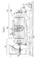
- a device 100 consists of three parts: a power supply part 101 in silica soot powder or in previously prepared silica granules, part recovery 103 of the doped and densified silica grains, and in between, a body main 102 used to carry out agglomeration operations (when starting from silica soot), doping and densification of the silica soot powder.
- the part power supply 101 is found in FIG. 1 to the left of the main body 102, and the part recovery 103 to his right.
- the feeding part 101 in silica soot powder or in silica granules includes a container 1 containing soot or silica granules 2, connected to means for distributing soot or silica granules, such as a screw helical 3 driven in a rotational movement about its axis 30 so as to ensure uniform distribution of soot or silica granules 2.
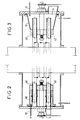
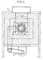
- the main body 102 of the device 100 mounted on a frame 105, comprises a set of tubes 4, in alumina for example, arranged parallel to each other others so that their axes 40 define a cylinder 51 (see FIG. 4), and serving as means for receiving the soot or the silica granules 2, the axes 40 of the tubes 4 being parallel to the axis 30.
- the set of tubes 4 is mounted in a support 45 of so as to be rotated about a common axis 50 which is that of the cylinder 51, parallel to axes 30 and 40, by rotation drive means 5 carried by the frame 105. Due to this rotation, one of the ends 41 (see FIG. 2) of each tubes 4 is successively in communication with the means of distribution 3. Thus, the soot or the silica granules 2 are introduced into the tubes of reception 4.
- ends 41 of the tubes 4 all open into a closed enclosure 10 into which the feed means 3 also open.
- the tubes 4 are also surrounded, over a large part of their length, by an oven 6 carried by the frame 105, having at each of its ends along axis 50 an opening (not referenced) to allow the passage of tubes 4 and their common rotation, and into which penetrate heating electrodes 60 for the heating the receiving tubes 4.
- the ends 41 of the tubes 4 are outside the oven 6 in the supply part 101 of the device 100, and the ends 42 of the tubes 4 (see FIG. 3), opposite the ends 41, are also found outside the oven 6 in the recovery part 103 of the device 100.
- the recovery part 103 of the device 100 comprises means 7 for supplying a precursor gas with a dopant with which it is desired to boost the silica.
- a precursor gas with which it is desired to boost the silica.
- It may for example be a fluorinating gas such as sulfur hexafluoride SF 6 or silicon tetrafluoride SiF 4 .
- the supply means 7 open into a closed enclosure 11 into which the ends 42 of the tubes 4 also open, so that the latter are thus all supplied with precursor gas.
- the precursor gas of the dopant is injected and circulates against the current with respect to the silica granules, which ensures better homogeneity of the doping than in the case where the gas circulates in the same direction as the silica granules.
- the enclosure 11 is also in communication, at its lower part, with a container 8 for collecting the densified and doped silica grains 9, located in the recovery part 103 of device 100.
- the gaseous reactive products of the doping reaction escape from the device 100 by the end 41 of the tubes 4 located at the supply part 101 of the latter, then by evacuation means 12 which communicate with the enclosure 10.
- the non-densified silica soot 2 is introduced into the device 100 by the end 41 of the receiving tubes 4 in which it is heated by the oven 6. Simultaneously, the precursor gas of the desired dopant (fluorine in the present example) is introduced into the device by the supply means 7 then by the end 42 of the receiving tubes 4.
- the precursor gas of the desired dopant fluorine in the present example
- Heating is carried out at high temperature, typically around 1350 ° C. when it is desired to carry out doping with fluorine.
- the silica granules are set in motion against the surface inside of the tubes 4 so that their entire surface is exposed to the action of the gas doping.
- the silica grains are doped homogeneously, which is not the case with the devices of the prior art.
- all the silica granules are exposed almost simultaneously to the action of the gas dopant, so that the process yield is improved compared to the processes using the static devices of the prior art.
- the granules roll on their inner surface, which facilitates processing.
- FIG. 5 a device 500 according to a second embodiment of the present invention.
- the device 500 also consists of three parts: a part supply 501 of silica soot powder, a recovery part 503 of the grains of doped and densified silica, and between the two, a main body 502 used to carry out the agglomeration, doping and densification operations of the silica soot powder.
- the supply part 501 is located in FIG. 5 to the left of the main body 502, and the recovery part 503 to its right.
- the supply part 501 of silica soot powder comprises a container 511 containing silica soot 512, connected to means for distributing the soot silica, such as a helical screw 513 driven in a rotational movement around its axis 530 so as to ensure a uniform distribution of the soot silica 512.
- the main body 502 of the device 500 mounted on a frame 505, comprises a tube 504, in alumina for example, serving as a means of receiving silica soot 512, the axis 540 of the tube 504 being coincident with the axis 530.
- the tube 504 is driven in rotation about its axis 540 by means of rotation drive 550 carried by the frame 505.
- One of the ends 541 of the tube 504 is in communication with the distribution means 513.
- the silica soot 2 is introduced into the tube reception 504.
- end 541 of the tube 504 opens into a closed enclosure 510 into which the feed means 513 also open.
- the tube 504 is also surrounded, over a large part of its length, by an oven 506 carried by the frame 505, having at each of its ends along axis 540 an opening (not referenced) to allow the passage of tube 504 and its rotation, and into which penetrate heating electrodes 560 for heating the receiving tube 504.
- the end 541 of the tube 504 is located outside the oven 506 in the supply part 501 of the device 100, and the end 542 of the tube 504, opposite at the end 541, is also outside the oven 506 in the recovery part 503 of device 500.
- the recovery part 503 of the device 500 comprises means 507 for supplying a precursor gas with a dopant with which it is desired to dop the silica. It may for example be a fluorinating gas such as sulfur hexafluoride SF 6 or silicon tetrafluoride SiF 4 .
- the supply means 507 open into a closed enclosure 514 into which also opens the end 542 of the tube 504, so that the latter is thus supplied with precursor gas.
- the precursor gas of the desired dopant is injected and circulates against the current with respect to the silica soot 512, which ensures good homogeneity of the doping.
- the enclosure 514 is also in communication, at its lower part, with a container 508 for collecting densified and doped silica grains 509, located in the recovery part 503 of the device 500.
- the gaseous reactive products of the doping reaction escape from the device 500 through the end 541 of the tube 504 located at the supply part 501 of the latter, then by evacuation means 515 which communicate with the enclosure 510.
- the operation of the device 500 according to the invention for doping soot of silica 512 is similar to the operation of the device 100 of FIGS. 1 to 4 for the doping of silica soot 2.
- the advantages of the device 500 are the same as those of device 100.
- the operation of the devices 100 and 500 according to the invention for doping of previously prepared silica granules 2 is identical to the operations described above, except for the fact that there is no agglomeration since the granules have been developed beforehand.
- the homogeneity of the doped silica grains obtained can be further improved if the device 100 or the device, or at least their main body 102 or 502, is inclined downward relative to the horizontal, by an angle of the order of 3 to 5 ° for example, between the entry of silica soot and the exit of the doped grains.
- the input and the output are separate, but this is not compulsory.
- the separation of the inlet and the outlet allows to carry out continuous doping with for example the manufacture of a fiber preform optical, by connecting the output of doped and densified silica grains to the silica distributor associated with a device for manufacturing such a preform.
- the material constituting the receiving tube or tubes may be any of the as long as it resists in particular the action of carbon derivatives, fluorine and any other dopant with which one wishes to boost silica, as well as abrasion.
- the temperature at which the soot or the silica granules introduced are brought to in the device according to the invention must be chosen in particular according to the flow of precursor gas.
- the processing time is a function of the speed of movement of the granules in the receiving means, itself a function of the inclination of these means of reception.
Landscapes
- Chemical & Material Sciences (AREA)
- Organic Chemistry (AREA)
- Inorganic Chemistry (AREA)
- Glass Melting And Manufacturing (AREA)
- Manufacture, Treatment Of Glass Fibers (AREA)
- Silicon Compounds (AREA)
- Physical Or Chemical Processes And Apparatus (AREA)
Claims (9)
- Vorrichtung zur Dotierung eines Kieselsäurepulvers mithilfe eines Dotiermittels, die umfaßt:dadurch gekennzeichnet, daß die Mittel zur Aufnahme (4; 504) bewegbar sind, so daß während ihrer Bewegung alle im Pulver enthaltenen Partikel (2; 512) sich so bewegen, daß dessen im wesentlichen gesamte Außenfläche der Atmosphäre ausgesetzt ist, welche die gasförmige Vorstufe enthält.Mittel zur Aufnahme (4; 504) des Kieselsäurepulvers;Mittel zur Erhitzung (6; 560) des in den Mitteln zur Aufnahme (4; 504) enthaltenen Pulvers, um dieses auf ein Temperatur zu bringen, die ausreicht, um die Verdichtung der enthaltenen Partikel (2; 512) zu ermöglichen, undMittel zur Zuführung (7; 507) einer gasförmigen Vorstufe des Dotiermittels zu den Aufnahmemitteln (4; 504), so daß das Pulver unter einer die gasförmige Vorstufe enthaltenden Atmosphäre erhitzt wird, was den Zusatz des Dotiermittels in das Pulver während dessen Verdichtung hervorruft, um ein dotiertes und verdichtetes Kieselsäurepulver (9; 509) zu gewinnen,
- Vorrichtung nach Anspruch 1,
dadurch gekennzeichnet, daß die Mittel zur Aufnahme (4; 504) eine Rotationsbewegung vollführen. - Vorrichtung nach einem der Ansprüche 1 oder 2,
dadurch gekennzeichnet, daß die Mittel zur Aufnahme (4; 504) im wesentlichen röhrenförmig sind und die Partikel des Kieselsäurepulvers in das Innere des oder der entsprechenden Röhren eingebracht werden. - Vorrichtung nach einem der Ansprüche 1 bis 3,
dadurch gekennzeichnet, daß die Mittel zur Aufnahme (4; 504) einen Eingang (41; 541) für die Partikel des nicht oder teilweise verdichteten Kieselsäurepulvers (2; 512) und einen Ausgang (42; 542) für die dotierten und verfestigten Kieselsäurepartikel aufweisen, wobei der Eingang (41; 541) von dem Ausgang (42; 542) getrennt ist. - Vorrichtung nach Anspruch 4,
dadurch gekennzeichnet, daß die Mittel zur Aufnahme (4; 504) so geneigt sind, daß die Partikel durch die Schwerkraft von dem Eingang (41; 541) zu dem Ausgang (42; 542) getrieben werden. - Vorrichtung nach einem der Ansprüche 4 oder 5,
dadurch gekennzeichnet, daß die Mittel zur Aufnahme (4; 504) gegenüber der Horizontalen geneigt sind. - Vorrichtung nach einem der Ansprüche 5 oder 6,
dadurch gekennzeichnet, daß die gasförmige Vorstufe so in die Mittel zur Aufnahme (4; 504) eingebracht wird, daß sie bezüglich der Partikel im Gegenstrom zirkuliert. - Vorrichtung nach einem der Ansprüche 1 bis 7,
dadurch gekennzeichnet, daß das Kieselsäurepulver anfänglich aus Partikeln aus Kieselsäureruß gebildet wird. - Vorrichtung nach einem der Ansprüche 1 bis 7,
dadurch gekennzeichnet, daß das Kieselsäurepulver anfänglich aus teilweise verdichtetem Kieselsäuregranulat gebildet wird.
Applications Claiming Priority (2)
| Application Number | Priority Date | Filing Date | Title |
|---|---|---|---|
| FR9606272A FR2749005B1 (fr) | 1996-05-21 | 1996-05-21 | Dispositif de dopage d'une poudre de silice |
| FR9606272 | 1996-05-21 |
Publications (2)
| Publication Number | Publication Date |
|---|---|
| EP0808799A1 EP0808799A1 (de) | 1997-11-26 |
| EP0808799B1 true EP0808799B1 (de) | 2000-07-19 |
Family
ID=9492303
Family Applications (1)
| Application Number | Title | Priority Date | Filing Date |
|---|---|---|---|
| EP97401080A Expired - Lifetime EP0808799B1 (de) | 1996-05-21 | 1997-05-15 | Vorrichtung zur Dotierung eines Kieselsäurepulvers |
Country Status (6)
| Country | Link |
|---|---|
| US (1) | US6007786A (de) |
| EP (1) | EP0808799B1 (de) |
| JP (1) | JP4101324B2 (de) |
| CA (1) | CA2207122A1 (de) |
| DE (1) | DE69702570T2 (de) |
| FR (1) | FR2749005B1 (de) |
Families Citing this family (11)
| Publication number | Priority date | Publication date | Assignee | Title |
|---|---|---|---|---|
| US7797966B2 (en) * | 2000-12-29 | 2010-09-21 | Single Crystal Technologies, Inc. | Hot substrate deposition of fused silica |
| US20020083739A1 (en) * | 2000-12-29 | 2002-07-04 | Pandelisev Kiril A. | Hot substrate deposition fiber optic preforms and preform components process and apparatus |
| US20020083740A1 (en) * | 2000-12-29 | 2002-07-04 | Pandelisev Kiril A. | Process and apparatus for production of silica grain having desired properties and their fiber optic and semiconductor application |
| US20020173416A1 (en) * | 2001-04-06 | 2002-11-21 | Ellison Adam J. | Dispersal of optically active ions in glass |
| FR2825357B1 (fr) * | 2001-05-31 | 2004-04-30 | Cit Alcatel | Procede de dopage de la silice par du fluor |
| US20030027054A1 (en) * | 2001-08-01 | 2003-02-06 | Ball Laura J. | Method for making photomask material by plasma induction |
| US20030027055A1 (en) * | 2001-08-01 | 2003-02-06 | Ball Laura J. | Method and feedstock for making photomask material |
| US7052541B2 (en) | 2002-06-19 | 2006-05-30 | Board Of Regents, The University Of Texas System | Color compositions |
| US20040187525A1 (en) * | 2003-03-31 | 2004-09-30 | Coffey Calvin T. | Method and apparatus for making soot |
| US7793612B2 (en) * | 2003-08-01 | 2010-09-14 | Silica Tech, Llc | Ring plasma jet method and apparatus for making an optical fiber preform |
| US7425235B2 (en) | 2005-02-11 | 2008-09-16 | The Board Of Regents Of The University Of Texas System | Color compositions and methods of manufacture |
Family Cites Families (3)
| Publication number | Priority date | Publication date | Assignee | Title |
|---|---|---|---|---|
| JPS62182127A (ja) * | 1986-02-05 | 1987-08-10 | Nippon Telegr & Teleph Corp <Ntt> | 石英系光フアイバ用母材の製造方法 |
| IT1219404B (it) * | 1988-06-27 | 1990-05-11 | Sip | Procedimento e apparecchiatura per la fabbricazione di fibre ottiche in silice |
| FR2693451B1 (fr) * | 1992-07-07 | 1994-08-19 | Alcatel Nv | Procédé de fabrication d'une poudre de silice et application d'une telle poudre à la réalisation d'une préforme pour fibre optique. |
-
1996
- 1996-05-21 FR FR9606272A patent/FR2749005B1/fr not_active Expired - Fee Related
-
1997
- 1997-05-15 DE DE69702570T patent/DE69702570T2/de not_active Expired - Lifetime
- 1997-05-15 EP EP97401080A patent/EP0808799B1/de not_active Expired - Lifetime
- 1997-05-20 US US08/862,172 patent/US6007786A/en not_active Expired - Lifetime
- 1997-05-20 CA CA002207122A patent/CA2207122A1/fr not_active Abandoned
- 1997-05-21 JP JP13087697A patent/JP4101324B2/ja not_active Expired - Fee Related
Also Published As
| Publication number | Publication date |
|---|---|
| EP0808799A1 (de) | 1997-11-26 |
| FR2749005B1 (fr) | 1998-07-10 |
| DE69702570T2 (de) | 2001-04-19 |
| JPH1087313A (ja) | 1998-04-07 |
| JP4101324B2 (ja) | 2008-06-18 |
| CA2207122A1 (fr) | 1997-11-21 |
| US6007786A (en) | 1999-12-28 |
| FR2749005A1 (fr) | 1997-11-28 |
| DE69702570D1 (de) | 2000-08-24 |
Similar Documents
| Publication | Publication Date | Title |
|---|---|---|
| EP0808799B1 (de) | Vorrichtung zur Dotierung eines Kieselsäurepulvers | |
| EP0578553B1 (de) | Verfahren zum Herstellen eines Siliciumdioxydpulvers und seine Verwendung bei der Herstellung einer optischen Faservorform | |
| JP5296207B2 (ja) | 窒素をドープした石英ガラスを製造する方法、及びその方法を実行するのに好適な石英ガラス粒 | |
| EP0054495B2 (de) | Optischer Wellenleiter mit einem mit Fluor dotierten Kern | |
| CN1307544A (zh) | 制造掺杂稀土金属的光导纤维预制棒的方法和设备 | |
| FR2480732A1 (fr) | Procede et bruleur pour la production de fines particules d'oxydes de metaux et de metalloides | |
| EP0086132B1 (de) | Verfahren zur Herstellung dopierten Siliziumglases für Verarbeitung von Vorformen für optische Fasern | |
| WO2008152272A2 (fr) | Synthese par pyrolyse laser de nanocristaux de silicium | |
| EP0519834B1 (de) | Verfahren und Vorrichtung zum Herstellen von Vorformen für optische Faser | |
| EP0034097A2 (de) | Verfahren zur Herstellung von Körpern, insbesondere einer Röhre aus transparentem Aluminiumoxid | |
| US5597398A (en) | Process for producing glass preform for optical fiber | |
| FR2496087A1 (fr) | Procede et appareil de fabrication d'ebauches poreuses de fibres optiques | |
| CA2088216C (fr) | Procede de fabrication d'une piece cylindrique en verre, notamment en verre fluore | |
| FR2540856A1 (fr) | Procede de fabrication de guide d'ondes lumineuses et en particulier d'une preforme ensuite etiree pour fournir le guide d'ondes | |
| EP1262456B1 (de) | Verfahren zur Herstellung eines Fluor-dotierten Kieselsäurepulvers | |
| EP0936194A1 (de) | Verfahren zur Aussenabscheidung von dotiertem Quarz auf einer Vorform für optische Fasern | |
| JP2003313033A (ja) | 光学用ガラスおよびその製造方法 | |
| CN1636902A (zh) | 掺氟石英玻璃件、光纤预型件和光纤的制造方法和光纤 | |
| EP1505039B1 (de) | Verfahren zur Herstellung einer Lichtleitfaservorform | |
| FR2568242A1 (fr) | Procede et appareil pour le depot en phase vapeur de verre dope | |
| JP5867976B2 (ja) | 光ファイバ母材の製造方法 | |
| EP0125964B1 (de) | Verfahren und Vorrichtung zur Kühlung eines Materials und Verwendung für die Herstellung von feuerfesten Materialien durch Härtung | |
| WO1996016911A1 (en) | Method and apparatus for producing optical fiber preform | |
| WO1992021629A1 (fr) | Procede de fabrication d'une fibre optique et fibre optique realisee selon ce procede | |
| FR2569180A1 (fr) | Procede de preparation de silice synthetique, notamment pour la fabrication de fibres optiques, silice synthetique et fibres optiques obtenues |
Legal Events
| Date | Code | Title | Description |
|---|---|---|---|
| PUAI | Public reference made under article 153(3) epc to a published international application that has entered the european phase |
Free format text: ORIGINAL CODE: 0009012 |
|
| AK | Designated contracting states |
Kind code of ref document: A1 Designated state(s): DE DK FI GB IT NL |
|
| 17P | Request for examination filed |
Effective date: 19980414 |
|
| 17Q | First examination report despatched |
Effective date: 19990209 |
|
| GRAG | Despatch of communication of intention to grant |
Free format text: ORIGINAL CODE: EPIDOS AGRA |
|
| GRAG | Despatch of communication of intention to grant |
Free format text: ORIGINAL CODE: EPIDOS AGRA |
|
| GRAH | Despatch of communication of intention to grant a patent |
Free format text: ORIGINAL CODE: EPIDOS IGRA |
|
| GRAH | Despatch of communication of intention to grant a patent |
Free format text: ORIGINAL CODE: EPIDOS IGRA |
|
| RAP1 | Party data changed (applicant data changed or rights of an application transferred) |
Owner name: ALCATEL |
|
| GRAA | (expected) grant |
Free format text: ORIGINAL CODE: 0009210 |
|
| AK | Designated contracting states |
Kind code of ref document: B1 Designated state(s): DE DK FI GB IT NL |
|
| PG25 | Lapsed in a contracting state [announced via postgrant information from national office to epo] |
Ref country code: FI Free format text: LAPSE BECAUSE OF FAILURE TO SUBMIT A TRANSLATION OF THE DESCRIPTION OR TO PAY THE FEE WITHIN THE PRESCRIBED TIME-LIMIT Effective date: 20000719 |
|
| REF | Corresponds to: |
Ref document number: 69702570 Country of ref document: DE Date of ref document: 20000824 |
|
| GBT | Gb: translation of ep patent filed (gb section 77(6)(a)/1977) |
Effective date: 20000821 |
|
| ITF | It: translation for a ep patent filed | ||
| PG25 | Lapsed in a contracting state [announced via postgrant information from national office to epo] |
Ref country code: DK Free format text: LAPSE BECAUSE OF FAILURE TO SUBMIT A TRANSLATION OF THE DESCRIPTION OR TO PAY THE FEE WITHIN THE PRESCRIBED TIME-LIMIT Effective date: 20001019 |
|
| PGFP | Annual fee paid to national office [announced via postgrant information from national office to epo] |
Ref country code: NL Payment date: 20010509 Year of fee payment: 5 |
|
| PLBE | No opposition filed within time limit |
Free format text: ORIGINAL CODE: 0009261 |
|
| STAA | Information on the status of an ep patent application or granted ep patent |
Free format text: STATUS: NO OPPOSITION FILED WITHIN TIME LIMIT |
|
| 26N | No opposition filed | ||
| REG | Reference to a national code |
Ref country code: GB Ref legal event code: IF02 |
|
| PG25 | Lapsed in a contracting state [announced via postgrant information from national office to epo] |
Ref country code: NL Free format text: LAPSE BECAUSE OF NON-PAYMENT OF DUE FEES Effective date: 20021201 |
|
| NLV4 | Nl: lapsed or anulled due to non-payment of the annual fee |
Effective date: 20021201 |
|
| PGFP | Annual fee paid to national office [announced via postgrant information from national office to epo] |
Ref country code: DE Payment date: 20120523 Year of fee payment: 16 |
|
| PGFP | Annual fee paid to national office [announced via postgrant information from national office to epo] |
Ref country code: GB Payment date: 20120522 Year of fee payment: 16 |
|
| PGFP | Annual fee paid to national office [announced via postgrant information from national office to epo] |
Ref country code: IT Payment date: 20120531 Year of fee payment: 16 |
|
| GBPC | Gb: european patent ceased through non-payment of renewal fee |
Effective date: 20130515 |
|
| PG25 | Lapsed in a contracting state [announced via postgrant information from national office to epo] |
Ref country code: DE Free format text: LAPSE BECAUSE OF NON-PAYMENT OF DUE FEES Effective date: 20131203 |
|
| REG | Reference to a national code |
Ref country code: DE Ref legal event code: R119 Ref document number: 69702570 Country of ref document: DE Effective date: 20131203 |
|
| PG25 | Lapsed in a contracting state [announced via postgrant information from national office to epo] |
Ref country code: IT Free format text: LAPSE BECAUSE OF NON-PAYMENT OF DUE FEES Effective date: 20130515 |
|
| PG25 | Lapsed in a contracting state [announced via postgrant information from national office to epo] |
Ref country code: GB Free format text: LAPSE BECAUSE OF NON-PAYMENT OF DUE FEES Effective date: 20130515 |