EP0808799B1 - Apparatus for doping silica powder - Google Patents
Apparatus for doping silica powder Download PDFInfo
- Publication number
- EP0808799B1 EP0808799B1 EP97401080A EP97401080A EP0808799B1 EP 0808799 B1 EP0808799 B1 EP 0808799B1 EP 97401080 A EP97401080 A EP 97401080A EP 97401080 A EP97401080 A EP 97401080A EP 0808799 B1 EP0808799 B1 EP 0808799B1
- Authority
- EP
- European Patent Office
- Prior art keywords
- silica
- granules
- receiving means
- particles
- doping
- Prior art date
- Legal status (The legal status is an assumption and is not a legal conclusion. Google has not performed a legal analysis and makes no representation as to the accuracy of the status listed.)
- Expired - Lifetime
Links
- VYPSYNLAJGMNEJ-UHFFFAOYSA-N Silicium dioxide Chemical compound O=[Si]=O VYPSYNLAJGMNEJ-UHFFFAOYSA-N 0.000 title claims description 176
- 239000000377 silicon dioxide Substances 0.000 title claims description 86
- 239000000843 powder Substances 0.000 title claims description 26
- 239000008187 granular material Substances 0.000 claims description 34
- 239000004071 soot Substances 0.000 claims description 29
- 239000002243 precursor Substances 0.000 claims description 25
- 239000002019 doping agent Substances 0.000 claims description 24
- 239000002245 particle Substances 0.000 claims description 19
- 238000000280 densification Methods 0.000 claims description 12
- 230000033001 locomotion Effects 0.000 claims description 12
- 238000010438 heat treatment Methods 0.000 claims description 8
- 230000005484 gravity Effects 0.000 claims description 2
- 239000007789 gas Substances 0.000 description 29
- 238000004519 manufacturing process Methods 0.000 description 10
- 238000000034 method Methods 0.000 description 10
- 238000011084 recovery Methods 0.000 description 10
- 239000013307 optical fiber Substances 0.000 description 9
- 229910052731 fluorine Inorganic materials 0.000 description 5
- 239000011737 fluorine Substances 0.000 description 5
- 238000012545 processing Methods 0.000 description 5
- PXGOKWXKJXAPGV-UHFFFAOYSA-N Fluorine Chemical compound FF PXGOKWXKJXAPGV-UHFFFAOYSA-N 0.000 description 4
- 229910018503 SF6 Inorganic materials 0.000 description 4
- 238000004891 communication Methods 0.000 description 4
- ABTOQLMXBSRXSM-UHFFFAOYSA-N silicon tetrafluoride Chemical compound F[Si](F)(F)F ABTOQLMXBSRXSM-UHFFFAOYSA-N 0.000 description 4
- SFZCNBIFKDRMGX-UHFFFAOYSA-N sulfur hexafluoride Chemical compound FS(F)(F)(F)(F)F SFZCNBIFKDRMGX-UHFFFAOYSA-N 0.000 description 4
- 229960000909 sulfur hexafluoride Drugs 0.000 description 4
- 238000005054 agglomeration Methods 0.000 description 3
- 230000002776 aggregation Effects 0.000 description 3
- PNEYBMLMFCGWSK-UHFFFAOYSA-N aluminium oxide Inorganic materials [O-2].[O-2].[O-2].[Al+3].[Al+3] PNEYBMLMFCGWSK-UHFFFAOYSA-N 0.000 description 2
- 238000006243 chemical reaction Methods 0.000 description 2
- 239000000460 chlorine Substances 0.000 description 2
- 238000009826 distribution Methods 0.000 description 2
- 238000010348 incorporation Methods 0.000 description 2
- 230000003287 optical effect Effects 0.000 description 2
- 238000009827 uniform distribution Methods 0.000 description 2
- VXEGSRKPIUDPQT-UHFFFAOYSA-N 4-[4-(4-methoxyphenyl)piperazin-1-yl]aniline Chemical compound C1=CC(OC)=CC=C1N1CCN(C=2C=CC(N)=CC=2)CC1 VXEGSRKPIUDPQT-UHFFFAOYSA-N 0.000 description 1
- 208000031968 Cadaver Diseases 0.000 description 1
- KZBUYRJDOAKODT-UHFFFAOYSA-N Chlorine Chemical compound ClCl KZBUYRJDOAKODT-UHFFFAOYSA-N 0.000 description 1
- 229910003902 SiCl 4 Inorganic materials 0.000 description 1
- HXELGNKCCDGMMN-UHFFFAOYSA-N [F].[Cl] Chemical compound [F].[Cl] HXELGNKCCDGMMN-UHFFFAOYSA-N 0.000 description 1
- 238000005299 abrasion Methods 0.000 description 1
- 230000005540 biological transmission Effects 0.000 description 1
- 230000015572 biosynthetic process Effects 0.000 description 1
- 150000001721 carbon Chemical class 0.000 description 1
- 238000005229 chemical vapour deposition Methods 0.000 description 1
- 229910052801 chlorine Inorganic materials 0.000 description 1
- 125000001309 chloro group Chemical group Cl* 0.000 description 1
- 238000005253 cladding Methods 0.000 description 1
- 238000007796 conventional method Methods 0.000 description 1
- 230000003247 decreasing effect Effects 0.000 description 1
- 238000000151 deposition Methods 0.000 description 1
- 230000008021 deposition Effects 0.000 description 1
- 238000009792 diffusion process Methods 0.000 description 1
- 230000000694 effects Effects 0.000 description 1
- 239000000835 fiber Substances 0.000 description 1
- 239000010419 fine particle Substances 0.000 description 1
- 238000003682 fluorination reaction Methods 0.000 description 1
- 125000001153 fluoro group Chemical group F* 0.000 description 1
- 229910052732 germanium Inorganic materials 0.000 description 1
- GNPVGFCGXDBREM-UHFFFAOYSA-N germanium atom Chemical compound [Ge] GNPVGFCGXDBREM-UHFFFAOYSA-N 0.000 description 1
- IXCSERBJSXMMFS-UHFFFAOYSA-N hcl hcl Chemical compound Cl.Cl IXCSERBJSXMMFS-UHFFFAOYSA-N 0.000 description 1
- 239000000463 material Substances 0.000 description 1
- 230000003647 oxidation Effects 0.000 description 1
- 238000007254 oxidation reaction Methods 0.000 description 1
- 235000020004 porter Nutrition 0.000 description 1
- 238000000926 separation method Methods 0.000 description 1
- 239000005049 silicon tetrachloride Substances 0.000 description 1
- 238000003980 solgel method Methods 0.000 description 1
- 230000003068 static effect Effects 0.000 description 1
- 238000007740 vapor deposition Methods 0.000 description 1
Images

Classifications
-
- C—CHEMISTRY; METALLURGY
- C01—INORGANIC CHEMISTRY
- C01B—NON-METALLIC ELEMENTS; COMPOUNDS THEREOF; METALLOIDS OR COMPOUNDS THEREOF NOT COVERED BY SUBCLASS C01C
- C01B33/00—Silicon; Compounds thereof
- C01B33/113—Silicon oxides; Hydrates thereof
- C01B33/12—Silica; Hydrates thereof, e.g. lepidoic silicic acid
- C01B33/18—Preparation of finely divided silica neither in sol nor in gel form; After-treatment thereof
-
- C—CHEMISTRY; METALLURGY
- C01—INORGANIC CHEMISTRY
- C01P—INDEXING SCHEME RELATING TO STRUCTURAL AND PHYSICAL ASPECTS OF SOLID INORGANIC COMPOUNDS
- C01P2002/00—Crystal-structural characteristics
- C01P2002/50—Solid solutions
- C01P2002/52—Solid solutions containing elements as dopants
- C01P2002/54—Solid solutions containing elements as dopants one element only
Definitions
- the present invention relates to a device for doping a silica powder.
- the powders obtained with a device according to the invention may be used in any type of application, and more particularly for the manufacture of optical fiber preforms.
- Doping is understood to mean an operation consisting in incorporating into the silica molecules one or more molecules of elements intended to modify their properties.
- silica is incorporated dopants intended to modify its refractive index, by increasing it or by decreasing according to whether the silica concerned is intended to constitute respectively, by example, the core or the optical cladding of an optical fiber.
- the dopants can be by example germanium, to increase the refractive index of silica, or fluorine for decrease.
- Silica ready to be used for the manufacture of optical fibers in particular comes in the form of a powder made up of grains of more or less size large, densified or not.
- the silica grains when densified, are intended for example to be used to perform plasma recharging of an optical fiber preform manufactured by the MCVD (Modified Chemical Vapor Deposition) method.
- MCVD Modified Chemical Vapor Deposition
- the silica grains when not densified, are generally of size lower than that of densified silica grains, and can be used for example for make a preform using the VAD (Vapor Axial Deposition) or OVD (Outside) method Vapor Deposition).
- VAD Very Axial Deposition
- OVD Outside method Vapor Deposition
- silica soot can be obtained in various ways well known to those skilled in the art. For example, it can be produced by oxidation in the presence of heat of a silica precursor gas, such as silicon tetrachloride SiCl 4 .
- the small particles of silica are agglomerated to form granules, then these granules are consolidated by a heating which makes it possible to eliminate the porosity which exists between the various particles which compose them, so that the grains obtained are dense.
- These grains generally have a size greater than one micron.
- a silica particle at an intermediate stage of the manufacture of densified silica grains is provided.
- the conventional method used to obtain a powder of doped silica grains consists in carrying out the densification operation of the granules under an atmosphere containing a gas precursor of the desired dopant.
- densification is carried out under an atmosphere containing a fluorinating gas such as sulfur hexafluoride SF 6 or silicon tetrafluoride SiF 4 .
- the non-densified silica granules are placed in a crucible which is placed in an oven to bring it to the temperature allowing densification to be carried out, the oven being supplied with precursor gas of the desired dopant. Doping occurs by diffusion of the F 2 dopant molecules in the silica granules, which leads to the formation of complex molecules of the SiO 2-x F 2x type .
- the crucible devices for implementing this type of process pose a number of problems.
- the major problem lies in the fact that, in order to obtain homogeneous doping, the processing time required is very long and the doping yield is very poor, which is penalizing. If we decrease the processing time, which increases the yield, the doping is inhomogeneous. Inhomogeneous doping of the grains of silica leads, for example for the application to the manufacture of optical fibers, to index variations unacceptable for performance in terms of transmission of these optical fibers.
- An object of the present invention is to develop a doping device silica powder allowing homogeneous doping, compatible with the use of silica in the manufacture of optical fibers, without penalizing the performance of the doping operation.
- Another object of the present invention is to develop a device for doping of silica powder for continuous doping.
- the device according to the invention since the particles of the powder of silica are in motion during densification, all of these particles, whatever their size and their initial position in the receiving means are subject to the action of the dopant precursor gas. So there are no more difficult and long particles to achieve. Doping is homogeneous without the performance of the doping operation be penalized.
- the reception means can be animated by a rotational movement. This allows the particles to roll over their surface and be thus even better exposed to the action of the precursor gas. This is facilitated when the receiving means have a substantially tubular shape.
- the reception means have an entry of non or partially densified silica powder particles and an outlet of the doped and densified silica particles, the inlet being separated from the exit. In combination with the movement of particles, this allows the continuous processing.
- the receiving means can be arranged so that the particles are entrained by gravity from the inlet to the outlet. So the means of reception can be tilted relative to the horizontal. This further improves exposure of the entire surface of the particles to the atmosphere containing the gas precursor.
- the precursor gas can be introduced into the means for receiving so as to flow against the current with respect to the particles, which again ensures better homogeneity of doping.
- the precursor gas is chosen from sulfur hexafluoride SF 6 , silicon tetrafluoride SiF 4 , freons.
- the precursor gas is chosen from hydrochloric acid HCl, chlorine gas Cl 2 or SOCl 2 .
- Mixed chlorine-fluorine doping can be achieved by mixing the gases previous.
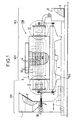
- a device 100 consists of three parts: a power supply part 101 in silica soot powder or in previously prepared silica granules, part recovery 103 of the doped and densified silica grains, and in between, a body main 102 used to carry out agglomeration operations (when starting from silica soot), doping and densification of the silica soot powder.
- the part power supply 101 is found in FIG. 1 to the left of the main body 102, and the part recovery 103 to his right.
- the feeding part 101 in silica soot powder or in silica granules includes a container 1 containing soot or silica granules 2, connected to means for distributing soot or silica granules, such as a screw helical 3 driven in a rotational movement about its axis 30 so as to ensure uniform distribution of soot or silica granules 2.
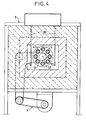
- the main body 102 of the device 100 mounted on a frame 105, comprises a set of tubes 4, in alumina for example, arranged parallel to each other others so that their axes 40 define a cylinder 51 (see FIG. 4), and serving as means for receiving the soot or the silica granules 2, the axes 40 of the tubes 4 being parallel to the axis 30.
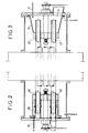
- the set of tubes 4 is mounted in a support 45 of so as to be rotated about a common axis 50 which is that of the cylinder 51, parallel to axes 30 and 40, by rotation drive means 5 carried by the frame 105. Due to this rotation, one of the ends 41 (see FIG. 2) of each tubes 4 is successively in communication with the means of distribution 3. Thus, the soot or the silica granules 2 are introduced into the tubes of reception 4.
- ends 41 of the tubes 4 all open into a closed enclosure 10 into which the feed means 3 also open.
- the tubes 4 are also surrounded, over a large part of their length, by an oven 6 carried by the frame 105, having at each of its ends along axis 50 an opening (not referenced) to allow the passage of tubes 4 and their common rotation, and into which penetrate heating electrodes 60 for the heating the receiving tubes 4.
- the ends 41 of the tubes 4 are outside the oven 6 in the supply part 101 of the device 100, and the ends 42 of the tubes 4 (see FIG. 3), opposite the ends 41, are also found outside the oven 6 in the recovery part 103 of the device 100.
- the recovery part 103 of the device 100 comprises means 7 for supplying a precursor gas with a dopant with which it is desired to boost the silica.
- a precursor gas with which it is desired to boost the silica.
- It may for example be a fluorinating gas such as sulfur hexafluoride SF 6 or silicon tetrafluoride SiF 4 .
- the supply means 7 open into a closed enclosure 11 into which the ends 42 of the tubes 4 also open, so that the latter are thus all supplied with precursor gas.
- the precursor gas of the dopant is injected and circulates against the current with respect to the silica granules, which ensures better homogeneity of the doping than in the case where the gas circulates in the same direction as the silica granules.
- the enclosure 11 is also in communication, at its lower part, with a container 8 for collecting the densified and doped silica grains 9, located in the recovery part 103 of device 100.
- the gaseous reactive products of the doping reaction escape from the device 100 by the end 41 of the tubes 4 located at the supply part 101 of the latter, then by evacuation means 12 which communicate with the enclosure 10.
- the non-densified silica soot 2 is introduced into the device 100 by the end 41 of the receiving tubes 4 in which it is heated by the oven 6. Simultaneously, the precursor gas of the desired dopant (fluorine in the present example) is introduced into the device by the supply means 7 then by the end 42 of the receiving tubes 4.
- the precursor gas of the desired dopant fluorine in the present example
- Heating is carried out at high temperature, typically around 1350 ° C. when it is desired to carry out doping with fluorine.
- the silica granules are set in motion against the surface inside of the tubes 4 so that their entire surface is exposed to the action of the gas doping.
- the silica grains are doped homogeneously, which is not the case with the devices of the prior art.
- all the silica granules are exposed almost simultaneously to the action of the gas dopant, so that the process yield is improved compared to the processes using the static devices of the prior art.
- the granules roll on their inner surface, which facilitates processing.
- FIG. 5 a device 500 according to a second embodiment of the present invention.
- the device 500 also consists of three parts: a part supply 501 of silica soot powder, a recovery part 503 of the grains of doped and densified silica, and between the two, a main body 502 used to carry out the agglomeration, doping and densification operations of the silica soot powder.
- the supply part 501 is located in FIG. 5 to the left of the main body 502, and the recovery part 503 to its right.
- the supply part 501 of silica soot powder comprises a container 511 containing silica soot 512, connected to means for distributing the soot silica, such as a helical screw 513 driven in a rotational movement around its axis 530 so as to ensure a uniform distribution of the soot silica 512.
- the main body 502 of the device 500 mounted on a frame 505, comprises a tube 504, in alumina for example, serving as a means of receiving silica soot 512, the axis 540 of the tube 504 being coincident with the axis 530.
- the tube 504 is driven in rotation about its axis 540 by means of rotation drive 550 carried by the frame 505.
- One of the ends 541 of the tube 504 is in communication with the distribution means 513.
- the silica soot 2 is introduced into the tube reception 504.
- end 541 of the tube 504 opens into a closed enclosure 510 into which the feed means 513 also open.
- the tube 504 is also surrounded, over a large part of its length, by an oven 506 carried by the frame 505, having at each of its ends along axis 540 an opening (not referenced) to allow the passage of tube 504 and its rotation, and into which penetrate heating electrodes 560 for heating the receiving tube 504.
- the end 541 of the tube 504 is located outside the oven 506 in the supply part 501 of the device 100, and the end 542 of the tube 504, opposite at the end 541, is also outside the oven 506 in the recovery part 503 of device 500.
- the recovery part 503 of the device 500 comprises means 507 for supplying a precursor gas with a dopant with which it is desired to dop the silica. It may for example be a fluorinating gas such as sulfur hexafluoride SF 6 or silicon tetrafluoride SiF 4 .
- the supply means 507 open into a closed enclosure 514 into which also opens the end 542 of the tube 504, so that the latter is thus supplied with precursor gas.
- the precursor gas of the desired dopant is injected and circulates against the current with respect to the silica soot 512, which ensures good homogeneity of the doping.
- the enclosure 514 is also in communication, at its lower part, with a container 508 for collecting densified and doped silica grains 509, located in the recovery part 503 of the device 500.
- the gaseous reactive products of the doping reaction escape from the device 500 through the end 541 of the tube 504 located at the supply part 501 of the latter, then by evacuation means 515 which communicate with the enclosure 510.
- the operation of the device 500 according to the invention for doping soot of silica 512 is similar to the operation of the device 100 of FIGS. 1 to 4 for the doping of silica soot 2.
- the advantages of the device 500 are the same as those of device 100.
- the operation of the devices 100 and 500 according to the invention for doping of previously prepared silica granules 2 is identical to the operations described above, except for the fact that there is no agglomeration since the granules have been developed beforehand.
- the homogeneity of the doped silica grains obtained can be further improved if the device 100 or the device, or at least their main body 102 or 502, is inclined downward relative to the horizontal, by an angle of the order of 3 to 5 ° for example, between the entry of silica soot and the exit of the doped grains.
- the input and the output are separate, but this is not compulsory.
- the separation of the inlet and the outlet allows to carry out continuous doping with for example the manufacture of a fiber preform optical, by connecting the output of doped and densified silica grains to the silica distributor associated with a device for manufacturing such a preform.
- the material constituting the receiving tube or tubes may be any of the as long as it resists in particular the action of carbon derivatives, fluorine and any other dopant with which one wishes to boost silica, as well as abrasion.
- the temperature at which the soot or the silica granules introduced are brought to in the device according to the invention must be chosen in particular according to the flow of precursor gas.
- the processing time is a function of the speed of movement of the granules in the receiving means, itself a function of the inclination of these means of reception.
Landscapes
- Chemical & Material Sciences (AREA)
- Organic Chemistry (AREA)
- Inorganic Chemistry (AREA)
- Glass Melting And Manufacturing (AREA)
- Manufacture, Treatment Of Glass Fibers (AREA)
- Silicon Compounds (AREA)
- Physical Or Chemical Processes And Apparatus (AREA)
Description
La présente invention concerne un dispositif de dopage d'une poudre de silice. De manière générale, les poudres obtenues avec un dispositif selon l'invention pourront être utilisées dans n'importe quel type d'application, et plus particulièrement pour la fabrication de préformes de fibres optiques.The present invention relates to a device for doping a silica powder. In general, the powders obtained with a device according to the invention may be used in any type of application, and more particularly for the manufacture of optical fiber preforms.
On entend par dopage une opération consistant à incorporer dans les molécules de silice une ou plusieurs molécules d'éléments destinés à en modifier les propriétés. Notamment, dans le domaine des fibres optiques, on incorpore dans la silice des dopants destinés à modifier son indice de réfraction, en l'augmentant ou en le diminuant selon que la silice concernée est destinée à constituer respectivement, par exemple, le coeur ou la gaine optique d'une fibre optique. Les dopants peuvent être par exemple le germanium, pour accroítre l'indice de réfraction de la silice, ou le fluor pour le diminuer.Doping is understood to mean an operation consisting in incorporating into the silica molecules one or more molecules of elements intended to modify their properties. In particular, in the field of optical fibers, silica is incorporated dopants intended to modify its refractive index, by increasing it or by decreasing according to whether the silica concerned is intended to constitute respectively, by example, the core or the optical cladding of an optical fiber. The dopants can be by example germanium, to increase the refractive index of silica, or fluorine for decrease.
La silice prête à être employée pour la fabrication de fibres optiques notamment se présente sous la forme d'une poudre constituée de grains de taille plus ou moins grande, densifiés ou non.Silica ready to be used for the manufacture of optical fibers in particular comes in the form of a powder made up of grains of more or less size large, densified or not.
Les grains de silice, lorsqu'ils sont densifiés, sont destinés par exemple à être utilisés pour effectuer la recharge plasma d'une préforme de fibre optique fabriquée par la méthode MCVD (Modified Chemical Vapor Deposition).The silica grains, when densified, are intended for example to be used to perform plasma recharging of an optical fiber preform manufactured by the MCVD (Modified Chemical Vapor Deposition) method.
Les grains de silice, lorsqu'ils ne sont pas densifiés, sont de taille généralement inférieure à celle des grains de silice densifiés, et peuvent être utilisés par exemple pour fabriquer une préforme par la méthode VAD (Vapor Axial Deposition) ou OVD (Outside Vapor Deposition).The silica grains, when not densified, are generally of size lower than that of densified silica grains, and can be used for example for make a preform using the VAD (Vapor Axial Deposition) or OVD (Outside) method Vapor Deposition).
Toutes ces méthodes, données uniquement à titre illustratif, la présente invention ne se limitant absolument pas à ces méthodes, sont bien connues de l'homme de l'art du domaine des fibres optiques, et ne seront pas décrites plus en détail ici.All these methods, given for illustrative purposes only, present invention by no means limited to these methods, are well known to man of the art of the field of optical fibers, and will not be described in more detail here.
Pour la fabrication des grains de silice densifiés, on part de grains de silice non densifiés, se trouvant sous la forme de très petites particules, de taille comprise entre 0,1 et 100 nm en général. La poudre de silice est dans ce cas dénommée suie. La suie de silice peut être obtenue de diverses manières bien connues de l'homme de l'art. Par exemple, elle peut être fabriquée par oxydation en présence de chaleur d'un gaz précurseur de la silice, tel que le tétrachlorure de silicium SiCl4. Pour la fabrication des grains de silice densifiés, les petites particules de silice sont agglomérées pour former des granulés, puis ces granulés sont consolidés par un chauffage qui permet d'éliminer la porosité qui existe entre les différentes particules qui les composent, de sorte que les grains obtenus sont denses. Ces grains ont en général une taille supérieure au micron.For the manufacture of densified silica grains, one starts with non-densified silica grains, being in the form of very small particles, of size between 0.1 and 100 nm in general. In this case, the silica powder is called soot. Silica soot can be obtained in various ways well known to those skilled in the art. For example, it can be produced by oxidation in the presence of heat of a silica precursor gas, such as silicon tetrachloride SiCl 4 . For the manufacture of the densified silica grains, the small particles of silica are agglomerated to form granules, then these granules are consolidated by a heating which makes it possible to eliminate the porosity which exists between the various particles which compose them, so that the grains obtained are dense. These grains generally have a size greater than one micron.
On appelle granulé de silice une particule de silice à un stade intermédiaire de la fabrication des grains de silice densifiés.A silica particle at an intermediate stage of the manufacture of densified silica grains.
La méthode classique utilisée pour obtenir une poudre de grains de silice dopée consiste à effectuer l'opération de densification des granulés sous une atmosphère contenant un gaz précurseur du dopant souhaité. Ainsi, pour effectuer la fluoration des granulés de silice, on effectue la densification sous une atmosphère contenant un gaz fluorant tel que l'hexafluorure de soufre SF6 ou le tétrafluorure de silicium SiF4. Les granulés de silice non densifiés sont disposés dans un creuset que l'on place dans un four pour le porter à la température permettant d'effectuer la densification, le four étant alimenté en gaz précurseur du dopant souhaité. Le dopage se produit par diffusion des molécules de dopant F2 dans les granulés de silice, ce qui conduit à la formation de molécules complexes du type SiO2-xF2x.The conventional method used to obtain a powder of doped silica grains consists in carrying out the densification operation of the granules under an atmosphere containing a gas precursor of the desired dopant. Thus, to effect the fluorination of the silica granules, densification is carried out under an atmosphere containing a fluorinating gas such as sulfur hexafluoride SF 6 or silicon tetrafluoride SiF 4 . The non-densified silica granules are placed in a crucible which is placed in an oven to bring it to the temperature allowing densification to be carried out, the oven being supplied with precursor gas of the desired dopant. Doping occurs by diffusion of the F 2 dopant molecules in the silica granules, which leads to the formation of complex molecules of the SiO 2-x F 2x type .
Les dispositifs à creuset pour la mise en oeuvre de ce type de procédés posent un certain nombre de problèmes.The crucible devices for implementing this type of process pose a number of problems.
Le problème majeur réside dans le fait que, pour obtenir un dopage homogène, le temps de traitement nécessaire est très long et le rendement du dopage est très médiocre, ce qui est pénalisant. Si l'on diminue le temps de traitement, ce qui augmente le rendement, le dopage est inhomogène. Or un dopage inhomogène des grains de silice conduit, par exemple pour l'application à la fabrication de fibres optiques, à des variations d'indice inacceptables pour les performances en termes de transmission de ces fibres optiques.The major problem lies in the fact that, in order to obtain homogeneous doping, the processing time required is very long and the doping yield is very poor, which is penalizing. If we decrease the processing time, which increases the yield, the doping is inhomogeneous. Inhomogeneous doping of the grains of silica leads, for example for the application to the manufacture of optical fibers, to index variations unacceptable for performance in terms of transmission of these optical fibers.
Un autre problème important provient du fait que le dopage est effectué de manière statique et requiert donc une première phase de montée en température du four, une deuxième phase de traitement à température sensiblement constante, puis une dernière phase de baisse en température avant de pouvoir récupérer les grains dopés et densifiés. Le procédé ne peut donc être mis en oeuvre en continu, ce qui est également pénalisant en termes de rendement.Another important problem stems from the fact that doping is carried out statically and therefore requires a first temperature rise phase of the oven, a second phase of treatment at substantially constant temperature, then a final temperature drop phase before the grains can be recovered doped and densified. The process cannot therefore be carried out continuously, which is also penalizing in terms of yield.
On connaít par ailleurs par le document EP-0 578 553 un procédé de fabrication d'une poudre de silice dopée par du fluor dans lequel la poudre de silice fabriquée par une méthode sol-gel est portée à haute température dans un four en présence de SiF4.We also know from document EP-0 578 553 a process for manufacturing a fluorine-doped silica powder in which the silica powder produced by a sol-gel method is brought to high temperature in an oven in the presence of SiF 4 .
Un but de la présente invention est de mettre au point un dispositif de dopage de poudre de silice permettant d'effectuer un dopage homogène, compatible avec l'utilisation de la silice dans la fabrication des fibres optiques, et ce sans pénaliser le rendement de l'opération de dopage.An object of the present invention is to develop a doping device silica powder allowing homogeneous doping, compatible with the use of silica in the manufacture of optical fibers, without penalizing the performance of the doping operation.
Un autre but de la présente invention est de mettre au point un dispositif de dopage de poudre de silice permettant d'effectuer le dopage en continu.Another object of the present invention is to develop a device for doping of silica powder for continuous doping.
La présente invention propose à cet effet un dispositif de dopage d'une poudre de silice à l'aide d'un dopant, comprenant :
- des moyens de réception de ladite poudre de silice,
- des moyens de chauffage de ladite poudre contenue dans lesdits moyens de réception, pour porter cette dernière à une température suffisante pour permettre la densification des particules qu'elle contient, et
- des moyens d'alimentation desdits moyens de réception en un gaz précurseur dudit dopant, de sorte que ladite poudre densifiée est chauffée sous une atmosphère contenant ledit gaz précurseur, ce qui provoque l'incorporation dudit dopant dans ladite poudre pendant sa densification pour obtenir une poudre de silice dopée et densifiée,
- means for receiving said silica powder,
- means for heating said powder contained in said receiving means, to bring the latter to a temperature sufficient to allow the densification of the particles which it contains, and
- means for supplying said receiving means with a precursor gas of said dopant, so that said densified powder is heated under an atmosphere containing said precursor gas, which causes the incorporation of said dopant in said powder during its densification to obtain a powder doped and densified silica,
Grâce au dispositif selon l'invention, puisque les particules de la poudre de silice sont en mouvement pendant la densification, toutes ces particules, quelle que soit leur taille et leur position initiale dans les moyens de réception sont soumis à l'action du gaz précurseur du dopant. Il n'y a donc plus de particules difficiles et longues à atteindre. Le dopage est homogène sans que le rendement de l'opération de dopage soit pénalisé.Thanks to the device according to the invention, since the particles of the powder of silica are in motion during densification, all of these particles, whatever their size and their initial position in the receiving means are subject to the action of the dopant precursor gas. So there are no more difficult and long particles to achieve. Doping is homogeneous without the performance of the doping operation be penalized.
De manière avantageuse, les moyens de réception peuvent être animés d'un mouvement de rotation. Ceci permet aux particules de rouler sur leur surface et d'être ainsi encore mieux exposés à l'action du gaz précurseur. Ceci est facilité lorsque les moyens de réception ont une forme sensiblement tubulaire.Advantageously, the reception means can be animated by a rotational movement. This allows the particles to roll over their surface and be thus even better exposed to the action of the precursor gas. This is facilitated when the receiving means have a substantially tubular shape.
Selon une autre caractéristique de l'invention, les moyens de réception comportent une entrée des particules de poudre de silice non ou partiellement densifiée et une sortie des particules de silice dopées et densifiées, l'entrée étant séparée de la sortie. En combinaison avec le mouvement des particules, ceci permet d'effectuer le traitement en continu.According to another characteristic of the invention, the reception means have an entry of non or partially densified silica powder particles and an outlet of the doped and densified silica particles, the inlet being separated from the exit. In combination with the movement of particles, this allows the continuous processing.
D'autre part, les moyens de réception peuvent être disposés de sorte que les particules sont entraínées par gravité de l'entrée vers la sortie. Ainsi, les moyens de réception peuvent être inclinés par rapport à l'horizontale. Ceci améliore encore l'exposition de toute la surface des particules à l'atmosphère contenant le gaz précurseur.On the other hand, the receiving means can be arranged so that the particles are entrained by gravity from the inlet to the outlet. So the means of reception can be tilted relative to the horizontal. This further improves exposure of the entire surface of the particles to the atmosphere containing the gas precursor.
Enfin, le gaz précurseur peut être introduit dans les moyens de réception de manière à circuler à contre-courant par rapport aux particules, ce qui assure encore une meilleure homogénéité du dopage.Finally, the precursor gas can be introduced into the means for receiving so as to flow against the current with respect to the particles, which again ensures better homogeneity of doping.
Lorsque le dopant est le fluor, le gaz précurseur est choisi parmi l'hexafluorure de soufre SF6, le tétrafluorure de silicium SiF4, les fréons.When the dopant is fluorine, the precursor gas is chosen from sulfur hexafluoride SF 6 , silicon tetrafluoride SiF 4 , freons.
Lorsque le dopant est le chlore, le gaz précurseur est choisi parmi l'acide chlorhydrique HCI, le chlore gazeux Cl2 ou le SOCl2.When the dopant is chlorine, the precursor gas is chosen from hydrochloric acid HCl, chlorine gas Cl 2 or SOCl 2 .
Un dopage mixte chlore-fluor peut être réalisé en mélangeant les gaz précédents.Mixed chlorine-fluorine doping can be achieved by mixing the gases previous.
D'autres caractéristiques et avantages de la présente invention apparaítront dans la description suivante d'un dispositif selon l'invention, donnée à titre d'exemple.Other characteristics and advantages of the present invention will appear in the following description of a device according to the invention, given by way of example.
Dans les figures suivantes :
- la figure 1 montre de manière schématique un dispositif selon un premier mode de réalisation de l'invention, partiellement en coupe longitudinale,
- la figure 2 est un grossissement de la partie Il de la figure 1,
- la figure 3 est un grossissement de la partie III de la figure 1,
- la figure 4 est une coupe transversale partielle du corps principal du dispositif de la figure 1,
- la figure 5 montre de manière schématique un dispositif selon un deuxième mode de réalisation de l'invention, partiellement en coupe longitudinale.
- FIG. 1 schematically shows a device according to a first embodiment of the invention, partially in longitudinal section,
- FIG. 2 is a magnification of part II of FIG. 1,
- FIG. 3 is a magnification of part III of FIG. 1,
- FIG. 4 is a partial cross section of the main body of the device in FIG. 1,
- Figure 5 shows schematically a device according to a second embodiment of the invention, partially in longitudinal section.
Dans toutes ces figures, les éléments communs portent les mêmes numéros de référence.In all these figures, the common elements have the same numbers of reference.
Un dispositif 100 selon un premier mode de réalisation de l'invention,
représenté aux figures 1 à 4, se compose de trois parties : une partie alimentation 101
en poudre de suie de silice ou en granulés de silice préalablement élaborés, une partie
récupération 103 des grains de silice dopés et densifiés, et entre les deux, un corps
principal 102 servant à effectuer les opérations d'agglomération (lorsque l'on part de
suie de silice), de dopage et de densification de la poudre de suie de silice. La partie
alimentation 101 se trouve sur la figure 1 à la gauche du corps principal 102, et la partie
récupération 103 à sa droite.A
La partie alimentation 101 en poudre de suie de silice ou en granulés de silice
comprend un récipient 1 contenant de la suie ou des granulés de silice 2, relié à des
moyens de distribution de la suie ou des granulés de silice, comme par exemple une vis
hélicoïdale 3 animée d'un mouvement de rotation autour de son axe 30 de manière à
assurer une distribution uniforme de la suie ou des granulés de silice 2.The feeding
Le corps principal 102 du dispositif 100, monté sur un bâti 105, comprend un
ensemble de tubes 4, en alumine par exemple, disposés parallèlement les uns aux
autres de sorte que leurs axes 40 définissent un cylindre 51 (voir figure 4), et servant de
moyens de réception de la suie ou des granulés de silice 2, les axes 40 des tubes 4
étant parallèles à l'axe 30. L'ensemble des tubes 4 est monté dans un support 45 de
manière à être entraíné en rotation autour d'un axe commun 50 qui est celui du cylindre
51, parallèle aux axes 30 et 40, par des moyens d'entraínement en rotation 5 portés par
le bâti 105. Du fait de cette rotation, l'une des extrémités 41 (voir figure 2) de chacun
des tubes 4 se trouve successivement en communication avec les moyens de
distribution 3. Ainsi, la suie ou les granulés de silice 2 sont introduits dans les tubes de
réception 4.The
On notera que les extrémités 41 des tubes 4 débouchent toutes dans une
enceinte fermée 10 dans laquelle débouchent également les moyens d'alimentation 3.It will be noted that the ends 41 of the
Les tubes 4 sont par ailleurs entourés, sur une grande partie de leur longueur,
par un four 6 porté par le bâti 105, présentant à chacune de ses extrémités le long de
l'axe 50 une ouverture (non référencée) pour permettre le passage des tubes 4 et leur
rotation commune, et dans lequel pénètrent des électrodes de chauffage 60 pour le
chauffage des tubes de réception 4. Les extrémités 41 des tubes 4 se trouvent
en-dehors du four 6 dans la partie alimentation 101 du dispositif 100, et les extrémités
42 des tubes 4 (voir figure 3), opposées aux extrémités 41, se trouvent également
en-dehors du four 6 dans la partie récupération 103 du dispositif 100.The
La partie récupération 103 du dispositif 100 comprend des moyens
d'alimentation 7 en gaz précurseur d'un dopant avec lequel on souhaite doper la silice.
Ce peut être par exemple un gaz fluorant tel que l'hexafluorure de soufre SF6 ou le
tétrafluorure de silicium SiF4. Les moyens d'alimentation 7 débouchent dans une
enceinte fermée 11 dans laquelle débouchent également les extrémités 42 des tubes 4,
de sorte que ces derniers sont ainsi tous alimentés en gaz précurseur. Ainsi, le gaz
précurseur du dopant est injecté et circule à contre-courant par rapport aux granulés de
silice, ce qui assure une homogénéité du dopage meilleure que dans le cas où le gaz
circule dans le même sens que les granulés de silice.The
L'enceinte 11 est également en communication, à sa partie inférieure, avec un
récipient 8 de récupération des grains de silice densifiés et dopés 9, se trouvant dans la
partie récupération 103 du dispositif 100. The enclosure 11 is also in communication, at its lower part, with a
container 8 for collecting the densified and doped
Les produits réactifs gazeux de la réaction de dopage s'échappent du dispositif
100 par l'extrémité 41 des tubes 4 se trouvant au niveau de la partie alimentation 101 de
ce dernier, puis par des moyens d'évacuation 12 qui communiquent avec l'enceinte 10.The gaseous reactive products of the doping reaction escape from the
On va maintenant décrire le fonctionnement du dispositif 100 selon l'invention
pour le dopage de suie de silice 2.We will now describe the operation of the
La suie de silice 2, non densifiée, est introduite dans le dispositif 100 par
l'extrémité 41 des tubes de réception 4 dans lesquels elle est chauffée par le four 6.
Simultanément, le gaz précurseur du dopant souhaité (le fluor dans l'exemple présent)
est introduit dans le dispositif par les moyens d'alimentation 7 puis par l'extrémité 42 des
tubes de réception 4.The non-densified silica soot 2 is introduced into the
Le chauffage est effectué à haute température, typiquement voisine de 1350°C lorsque l'on souhaite effectuer un dopage par du fluor. De ce fait, les particules très fines constituant la suie de silice 2 s'agglomèrent pour former des granulés de silice poreux dans lesquels s'incorpore le dopant provenant du gaz précurseur et de manière simultanée, les granulés ainsi dopés se consolident pour former des grains de silice dopés et densifiés 9 qui sont récupérés dans le récipient 8.Heating is carried out at high temperature, typically around 1350 ° C. when it is desired to carry out doping with fluorine. As a result, very fine particles constituting the silica soot 2 agglomerate to form porous silica granules in which the dopant from the precursor gas is incorporated and so simultaneously, the thus doped granules consolidate to form grains of silica doped and densified 9 which are recovered in the container 8.
Grâce à la rotation de l'ensemble des tubes 4 autour de l'axe 50 durant la mise
en oeuvre du procédé, les granulés de silice sont mis en mouvement contre la surface
intérieure des tubes 4 de sorte que toute leur surface est exposée à l'action du gaz
dopant.Thanks to the rotation of all the
Ainsi, grâce au dispositif selon l'invention, tous les grains de silice sont dopés de manière homogène, ce qui n'est pas le cas avec les dispositifs de l'art antérieur. De plus, tous les granulés de silice sont exposés quasiment simultanément à l'action du gaz dopant, de sorte que le rendement du procédé est amélioré par rapport aux procédés utilisant les dispositifs statiques de l'art antérieur.Thus, thanks to the device according to the invention, all the silica grains are doped homogeneously, which is not the case with the devices of the prior art. Of more, all the silica granules are exposed almost simultaneously to the action of the gas dopant, so that the process yield is improved compared to the processes using the static devices of the prior art.
Comme les tubes de réception sont en rotation, les granulés roulent sur leur surface intérieure, ce qui facilite le traitement. Toutefois, selon l'invention, on peut choisir n'importe quelle géométrie pour la surface des moyens de réception, et n'importe quel type de mouvement d'entraínement, du moment que l'ensemble de la surface de chaque granulé est exposée à l'action du gaz dopant.As the receiving tubes are rotating, the granules roll on their inner surface, which facilitates processing. However, according to the invention, one can choose any geometry for the surface of the receiving means, and any type of drive movement, as long as the entire surface of each granulated is exposed to the action of the doping gas.
On va maintenant décrire, en relation avec la figure 5, un dispositif 500 selon un deuxième mode de réalisation de la présente invention.We will now describe, in relation to FIG. 5, a device 500 according to a second embodiment of the present invention.
Le dispositif 500 se compose également de trois parties : une partie
alimentation 501 en poudre de suie de silice, une partie récupération 503 des grains de
silice dopés et densifiés, et entre les deux, un corps principal 502 servant à effectuer les
opérations d'agglomération, de dopage et de densification de la poudre de suie de silice.
La partie alimentation 501 se trouve sur la figure 5 à la gauche du corps principal 502, et
la partie récupération 503 à sa droite.The device 500 also consists of three parts: a
La partie alimentation 501 en poudre de suie de silice comprend un récipient
511 contenant de la suie de silice 512, relié à des moyens de distribution de la suie de
silice, comme par exemple une vis hélicoïdale 513 animée d'un mouvement de rotation
autour de son axe 530 de manière à assurer une distribution uniforme de la suie de
silice 512.The
Le corps principal 502 du dispositif 500, monté sur un bâti 505, comprend un
tube 504, en alumine par exemple, servant de moyen de réception de la suie de silice
512, l'axe 540 du tube 504 étant confondu avec l'axe 530. Le tube 504 est entraíné en
rotation autour de son axe 540 par des moyens d'entraínement en rotation 550 portés
par le bâti 505. L'une des extrémités 541 du tube 504 est en communication avec les
moyens de distribution 513. Ainsi, la suie de silice 2 est introduite dans le tube de
réception 504.The
On notera que l'extrémité 541 du tube 504 débouche dans une enceinte fermée
510 dans laquelle débouchent également les moyens d'alimentation 513.It will be noted that the
Le tube 504 est par ailleurs entouré, sur une grande partie de sa longueur, par
un four 506 porté par le bâti 505, présentant à chacune de ses extrémités le long de
l'axe 540 une ouverture (non référencée) pour permettre le passage du tube 504 et sa
rotation, et dans lequel pénètrent des électrodes de chauffage 560 pour le chauffage du
tube de réception 504. L'extrémité 541 du tube 504 se trouve en-dehors du four 506
dans la partie alimentation 501 du dispositif 100, et l'extrémité 542 du tube 504, opposée
à l'extrémité 541, se trouve également en-dehors du four 506 dans la partie récupération
503 du dispositif 500.The
La partie récupération 503 du dispositif 500 comprend des moyens
d'alimentation 507 en gaz précurseur d'un dopant avec lequel on souhaite doper la
silice. Ce peut être par exemple un gaz fluorant tel que l'hexafluorure de soufre SF6 ou
le tétrafluorure de silicium SiF4. Les moyens d'alimentation 507 débouchent dans une
enceinte fermée 514 dans laquelle débouche également l'extrémité 542 du tube 504, de
sorte que ce dernier est ainsi alimenté en gaz précurseur. Ainsi, le gaz précurseur du
dopant souhaité est injecté et circule à contre-courant par rapport à la suie de silice 512,
ce qui assure une bonne homogénéité du dopage.The
L'enceinte 514 est également en communication, à sa partie inférieure, avec un
récipient 508 de récupération des grains de silice densifiés et dopés 509, se trouvant
dans la partie récupération 503 du dispositif 500. The
Les produits réactifs gazeux de la réaction de dopage s'échappent du dispositif
500 par l'extrémité 541 du tube 504 se trouvant au niveau de la partie alimentation 501
de ce dernier, puis par des moyens d'évacuation 515 qui communiquent avec l'enceinte
510.The gaseous reactive products of the doping reaction escape from the device
500 through the
Le fonctionnement du dispositif 500 selon l'invention pour le dopage de la suie
de silice 512 est similaire au fonctionnement du dispositif 100 des figures 1 à 4 pour le
dopage de la suie de silice 2. Les avantages du dispositif 500 sont les mêmes que ceux
du dispositif 100.The operation of the device 500 according to the invention for doping soot
of
Le fonctionnement des dispositifs 100 et 500 selon l'invention pour le dopage
de granulés de silice 2 préalablement élaborés est identique aux fonctionnements
décrits ci-dessus, excepté le fait qu'il n'y a pas d'agglomération puisque les granulés ont
été élaborés au préalable.The operation of the
Bien entendu, la présente invention n'est pas limitée aux modes de réalisation qui viennent d'être décrits.Of course, the present invention is not limited to the embodiments which have just been described.
En particulier, l'homogénéité des grains de silice dopés obtenus peut être
encore améliorée si le dispositif 100 ou le dispositif, ou au moins leur corps principal 102
ou 502, est incliné vers le bas par rapport à l'horizontale, d'un angle de l'ordre de 3 à 5°
par exemple, entre l'entrée de suie de silice et la sortie des grains dopés.In particular, the homogeneity of the doped silica grains obtained can be
further improved if the
Dans les modes de réalisation décrits, l'entrée et la sortie sont séparées, mais cela n'est pas obligatoire. Cependant, la séparation de l'entrée et de la sortie permet d'effectuer un dopage en continu avec par exemple la fabrication d'une préforme de fibre optique, en reliant la sortie de grains de silice dopés et densifiés au distributeur de silice associé à un dispositif de fabrication d'une telle préforme.In the embodiments described, the input and the output are separate, but this is not compulsory. However, the separation of the inlet and the outlet allows to carry out continuous doping with for example the manufacture of a fiber preform optical, by connecting the output of doped and densified silica grains to the silica distributor associated with a device for manufacturing such a preform.
Le matériau constituant le ou les tubes de réception peut être quelconque du moment qu'il résiste notamment à l'action de dérivés carbonés, du fluor et de tout autre dopant avec lequel on souhaite doper la silice, ainsi qu'à l'abrasion.The material constituting the receiving tube or tubes may be any of the as long as it resists in particular the action of carbon derivatives, fluorine and any other dopant with which one wishes to boost silica, as well as abrasion.
La température à laquelle sont portés la suie ou les granulés de silice introduits dans le dispositif selon l'invention doit être choisie notamment en fonction du débit de gaz précurseur. Le temps de traitement est fonction de la vitesse du mouvement des granulés dans les moyens de réception, elle-même fonction de l'inclinaison de ces moyens de réception.The temperature at which the soot or the silica granules introduced are brought to in the device according to the invention must be chosen in particular according to the flow of precursor gas. The processing time is a function of the speed of movement of the granules in the receiving means, itself a function of the inclination of these means of reception.
Claims (9)
- A device for doping silica powder with a dopant, including:characterized in that said receiving means (4; 504) are mobile so that, during their movement, each of said granules (2; 512) of said particles that they contain is subject to movement such that substantially all of its outside surface is exposed to the atmosphere containing said precursor gas.silica soot particle receiving means (4; 504),means for heating (6; 560) said particles contained in said receiving means (4; 504) to a temperature sufficient to allow densification of the granules (2; 512) they contain, andmeans (7; 507) for feeding said receiving means (4; 504) with a precursor gas of said dopant so that said granules are heated in an atmosphere containing said precursor gas, which causes said dopant to be incorporated into said granules during their densification to produce densified and doped silica grains (9; 509),
- The device claimed in claim 1, characterized in that said receiving means (4; 504) are subjected to a rotational movement.
- The device claimed in claim 1 or 2, characterized in that said receiving means (4; 504) are substantially tubular, said particles of said silica granules being introduced into the interior of the corresponding tube(s).
- The device claimed in any one of claims 1 to 3, characterized in that said receiving means (4; 504) have an inlet (41; 541) for granules of said partially densified or non-densified silica particles (2; 512) and a consolidated and doped silica grain (9; 509) outlet (42; 542), said inlet (41; 541) being separate from said outlet (42; 542).
- The device claimed in claim 4, characterized in that said receiving means (4; 504) are inclined so that said granules are entrained by gravity from said inlet (41; 541) to said outlet (42; 542).
- The device claimed in claim 4 or claim 5, characterized in that said receiving means (4; 504) are inclined to the horizontal.
- The device claimed in claim 5 or claim 6, characterized in that said precursor gas is introduced into said receiving means (4; 504) in a counterflow arrangement relative to said granules.
- The device claimed in any one of claims 1 to 7, characterized in that said silica particles are initially silica soot granules.
- The device claimed in any one of claims 1 to 7, characterized in that said silica particles are initially partially densified silica granules.
Applications Claiming Priority (2)
| Application Number | Priority Date | Filing Date | Title |
|---|---|---|---|
| FR9606272A FR2749005B1 (en) | 1996-05-21 | 1996-05-21 | DEVICE FOR DOPING A SILICA POWDER |
| FR9606272 | 1996-05-21 |
Publications (2)
| Publication Number | Publication Date |
|---|---|
| EP0808799A1 EP0808799A1 (en) | 1997-11-26 |
| EP0808799B1 true EP0808799B1 (en) | 2000-07-19 |
Family
ID=9492303
Family Applications (1)
| Application Number | Title | Priority Date | Filing Date |
|---|---|---|---|
| EP97401080A Expired - Lifetime EP0808799B1 (en) | 1996-05-21 | 1997-05-15 | Apparatus for doping silica powder |
Country Status (6)
| Country | Link |
|---|---|
| US (1) | US6007786A (en) |
| EP (1) | EP0808799B1 (en) |
| JP (1) | JP4101324B2 (en) |
| CA (1) | CA2207122A1 (en) |
| DE (1) | DE69702570T2 (en) |
| FR (1) | FR2749005B1 (en) |
Families Citing this family (11)
| Publication number | Priority date | Publication date | Assignee | Title |
|---|---|---|---|---|
| US7797966B2 (en) * | 2000-12-29 | 2010-09-21 | Single Crystal Technologies, Inc. | Hot substrate deposition of fused silica |
| US20020083739A1 (en) * | 2000-12-29 | 2002-07-04 | Pandelisev Kiril A. | Hot substrate deposition fiber optic preforms and preform components process and apparatus |
| US20020083740A1 (en) * | 2000-12-29 | 2002-07-04 | Pandelisev Kiril A. | Process and apparatus for production of silica grain having desired properties and their fiber optic and semiconductor application |
| US20020173416A1 (en) * | 2001-04-06 | 2002-11-21 | Ellison Adam J. | Dispersal of optically active ions in glass |
| FR2825357B1 (en) * | 2001-05-31 | 2004-04-30 | Cit Alcatel | PROCESS FOR DOPING SILICA WITH FLUORINE |
| US20030027054A1 (en) * | 2001-08-01 | 2003-02-06 | Ball Laura J. | Method for making photomask material by plasma induction |
| US20030027055A1 (en) * | 2001-08-01 | 2003-02-06 | Ball Laura J. | Method and feedstock for making photomask material |
| US7052541B2 (en) | 2002-06-19 | 2006-05-30 | Board Of Regents, The University Of Texas System | Color compositions |
| US20040187525A1 (en) * | 2003-03-31 | 2004-09-30 | Coffey Calvin T. | Method and apparatus for making soot |
| US7793612B2 (en) * | 2003-08-01 | 2010-09-14 | Silica Tech, Llc | Ring plasma jet method and apparatus for making an optical fiber preform |
| US7425235B2 (en) | 2005-02-11 | 2008-09-16 | The Board Of Regents Of The University Of Texas System | Color compositions and methods of manufacture |
Family Cites Families (3)
| Publication number | Priority date | Publication date | Assignee | Title |
|---|---|---|---|---|
| JPS62182127A (en) * | 1986-02-05 | 1987-08-10 | Nippon Telegr & Teleph Corp <Ntt> | Production of preform for quartz based optical fiber |
| IT1219404B (en) * | 1988-06-27 | 1990-05-11 | Sip | PROCEDURE AND EQUIPMENT FOR THE MANUFACTURE OF FIBER OPTICS IN SILICA |
| FR2693451B1 (en) * | 1992-07-07 | 1994-08-19 | Alcatel Nv | Method of manufacturing a silica powder and application of such a powder to the production of a preform for optical fiber. |
-
1996
- 1996-05-21 FR FR9606272A patent/FR2749005B1/en not_active Expired - Fee Related
-
1997
- 1997-05-15 DE DE69702570T patent/DE69702570T2/en not_active Expired - Lifetime
- 1997-05-15 EP EP97401080A patent/EP0808799B1/en not_active Expired - Lifetime
- 1997-05-20 US US08/862,172 patent/US6007786A/en not_active Expired - Lifetime
- 1997-05-20 CA CA002207122A patent/CA2207122A1/en not_active Abandoned
- 1997-05-21 JP JP13087697A patent/JP4101324B2/en not_active Expired - Fee Related
Also Published As
| Publication number | Publication date |
|---|---|
| EP0808799A1 (en) | 1997-11-26 |
| FR2749005B1 (en) | 1998-07-10 |
| DE69702570T2 (en) | 2001-04-19 |
| JPH1087313A (en) | 1998-04-07 |
| JP4101324B2 (en) | 2008-06-18 |
| CA2207122A1 (en) | 1997-11-21 |
| US6007786A (en) | 1999-12-28 |
| FR2749005A1 (en) | 1997-11-28 |
| DE69702570D1 (en) | 2000-08-24 |
Similar Documents
| Publication | Publication Date | Title |
|---|---|---|
| EP0808799B1 (en) | Apparatus for doping silica powder | |
| EP0578553B1 (en) | Process of making a silica powder and use of such a powder in the manufacture of optical fibre preforms | |
| JP5296207B2 (en) | Method for producing nitrogen-doped quartz glass and quartz glass grains suitable for carrying out the method | |
| EP0054495B2 (en) | Optical waveguide with a fluor-doped core | |
| CN1307544A (en) | Method and apparatus for making optical fiber preform doped with rare earth metals | |
| FR2480732A1 (en) | PROCESS AND BURNER FOR THE PRODUCTION OF FINE PARTICLES OF OXIDES OF METALS AND METALLOIDS | |
| EP0086132B1 (en) | Method of making doped silica glass for processing a preform for an optical fibre | |
| WO2008152272A2 (en) | Synthesis of silicon nanocrystals by laser pyrolysis | |
| EP0519834B1 (en) | Process and device for the manufacture of preforms for optical fibres | |
| EP0034097A2 (en) | Process for producing translucent alumima bodies, especially tubes | |
| US5597398A (en) | Process for producing glass preform for optical fiber | |
| FR2496087A1 (en) | PROCESS AND APPARATUS FOR MANUFACTURING POROUS LAMPS OF OPTICAL FIBERS | |
| CA2088216C (en) | Process for manufacturing glass cylindrical article especially fluorated glass | |
| FR2540856A1 (en) | METHOD FOR MANUFACTURING THE LIGHT WAVE GUIDE AND IN PARTICULAR A PREFORM BEYONDED TO PROVIDE THE WAVEGUIDE | |
| EP1262456B1 (en) | Process for preparing a fluorine-doped silica pulver | |
| EP0936194A1 (en) | Process for external deposition of doped silica on an optical fibre preform | |
| JP2003313033A (en) | Optical glass and manufacturing method thereof | |
| CN1636902A (en) | Method for manufacturing fluorine-doped silica glass, optical fiber preform, and optical fiber, and optical fiber | |
| EP1505039B1 (en) | Method of manufacturing an optical fiber preform | |
| FR2568242A1 (en) | PROCESS AND APPARATUS FOR VAPOR DEPOSITION OF DOPED GLASS | |
| JP5867976B2 (en) | Optical fiber preform manufacturing method | |
| EP0125964B1 (en) | Process and apparatus for cooling a material and application to the manufacture of refractory materials by tempering | |
| WO1996016911A1 (en) | Method and apparatus for producing optical fiber preform | |
| WO1992021629A1 (en) | Method for producing an optical fibre, and optical fibre thereby obtained | |
| FR2569180A1 (en) | Process for the preparation of synthetic silica, especially for the manufacture of optical fibres, synthetic silica and optical fibres obtained |
Legal Events
| Date | Code | Title | Description |
|---|---|---|---|
| PUAI | Public reference made under article 153(3) epc to a published international application that has entered the european phase |
Free format text: ORIGINAL CODE: 0009012 |
|
| AK | Designated contracting states |
Kind code of ref document: A1 Designated state(s): DE DK FI GB IT NL |
|
| 17P | Request for examination filed |
Effective date: 19980414 |
|
| 17Q | First examination report despatched |
Effective date: 19990209 |
|
| GRAG | Despatch of communication of intention to grant |
Free format text: ORIGINAL CODE: EPIDOS AGRA |
|
| GRAG | Despatch of communication of intention to grant |
Free format text: ORIGINAL CODE: EPIDOS AGRA |
|
| GRAH | Despatch of communication of intention to grant a patent |
Free format text: ORIGINAL CODE: EPIDOS IGRA |
|
| GRAH | Despatch of communication of intention to grant a patent |
Free format text: ORIGINAL CODE: EPIDOS IGRA |
|
| RAP1 | Party data changed (applicant data changed or rights of an application transferred) |
Owner name: ALCATEL |
|
| GRAA | (expected) grant |
Free format text: ORIGINAL CODE: 0009210 |
|
| AK | Designated contracting states |
Kind code of ref document: B1 Designated state(s): DE DK FI GB IT NL |
|
| PG25 | Lapsed in a contracting state [announced via postgrant information from national office to epo] |
Ref country code: FI Free format text: LAPSE BECAUSE OF FAILURE TO SUBMIT A TRANSLATION OF THE DESCRIPTION OR TO PAY THE FEE WITHIN THE PRESCRIBED TIME-LIMIT Effective date: 20000719 |
|
| REF | Corresponds to: |
Ref document number: 69702570 Country of ref document: DE Date of ref document: 20000824 |
|
| GBT | Gb: translation of ep patent filed (gb section 77(6)(a)/1977) |
Effective date: 20000821 |
|
| ITF | It: translation for a ep patent filed | ||
| PG25 | Lapsed in a contracting state [announced via postgrant information from national office to epo] |
Ref country code: DK Free format text: LAPSE BECAUSE OF FAILURE TO SUBMIT A TRANSLATION OF THE DESCRIPTION OR TO PAY THE FEE WITHIN THE PRESCRIBED TIME-LIMIT Effective date: 20001019 |
|
| PGFP | Annual fee paid to national office [announced via postgrant information from national office to epo] |
Ref country code: NL Payment date: 20010509 Year of fee payment: 5 |
|
| PLBE | No opposition filed within time limit |
Free format text: ORIGINAL CODE: 0009261 |
|
| STAA | Information on the status of an ep patent application or granted ep patent |
Free format text: STATUS: NO OPPOSITION FILED WITHIN TIME LIMIT |
|
| 26N | No opposition filed | ||
| REG | Reference to a national code |
Ref country code: GB Ref legal event code: IF02 |
|
| PG25 | Lapsed in a contracting state [announced via postgrant information from national office to epo] |
Ref country code: NL Free format text: LAPSE BECAUSE OF NON-PAYMENT OF DUE FEES Effective date: 20021201 |
|
| NLV4 | Nl: lapsed or anulled due to non-payment of the annual fee |
Effective date: 20021201 |
|
| PGFP | Annual fee paid to national office [announced via postgrant information from national office to epo] |
Ref country code: DE Payment date: 20120523 Year of fee payment: 16 |
|
| PGFP | Annual fee paid to national office [announced via postgrant information from national office to epo] |
Ref country code: GB Payment date: 20120522 Year of fee payment: 16 |
|
| PGFP | Annual fee paid to national office [announced via postgrant information from national office to epo] |
Ref country code: IT Payment date: 20120531 Year of fee payment: 16 |
|
| GBPC | Gb: european patent ceased through non-payment of renewal fee |
Effective date: 20130515 |
|
| PG25 | Lapsed in a contracting state [announced via postgrant information from national office to epo] |
Ref country code: DE Free format text: LAPSE BECAUSE OF NON-PAYMENT OF DUE FEES Effective date: 20131203 |
|
| REG | Reference to a national code |
Ref country code: DE Ref legal event code: R119 Ref document number: 69702570 Country of ref document: DE Effective date: 20131203 |
|
| PG25 | Lapsed in a contracting state [announced via postgrant information from national office to epo] |
Ref country code: IT Free format text: LAPSE BECAUSE OF NON-PAYMENT OF DUE FEES Effective date: 20130515 |
|
| PG25 | Lapsed in a contracting state [announced via postgrant information from national office to epo] |
Ref country code: GB Free format text: LAPSE BECAUSE OF NON-PAYMENT OF DUE FEES Effective date: 20130515 |