EP0808397B1 - Structure comprenant un reseau de poutres maintenues par des entretoises, et facade aeree par l'arriere soutenue par ladite structure - Google Patents
Structure comprenant un reseau de poutres maintenues par des entretoises, et facade aeree par l'arriere soutenue par ladite structure Download PDFInfo
- Publication number
- EP0808397B1 EP0808397B1 EP96902985A EP96902985A EP0808397B1 EP 0808397 B1 EP0808397 B1 EP 0808397B1 EP 96902985 A EP96902985 A EP 96902985A EP 96902985 A EP96902985 A EP 96902985A EP 0808397 B1 EP0808397 B1 EP 0808397B1
- Authority
- EP
- European Patent Office
- Prior art keywords
- struts
- ball
- facade according
- facade
- threaded
- Prior art date
- Legal status (The legal status is an assumption and is not a legal conclusion. Google has not performed a legal analysis and makes no representation as to the accuracy of the status listed.)
- Expired - Lifetime
Links
- 125000006850 spacer group Chemical group 0.000 title claims description 7
- 230000008878 coupling Effects 0.000 claims description 8
- 238000010168 coupling process Methods 0.000 claims description 8
- 238000005859 coupling reaction Methods 0.000 claims description 8
- 229910052751 metal Inorganic materials 0.000 claims description 8
- 239000002184 metal Substances 0.000 claims description 8
- 238000003825 pressing Methods 0.000 claims description 4
- 230000036961 partial effect Effects 0.000 claims description 3
- 229920002994 synthetic fiber Polymers 0.000 claims 3
- 238000010276 construction Methods 0.000 claims 2
- 230000000717 retained effect Effects 0.000 claims 2
- 241000251131 Sphyrna Species 0.000 claims 1
- 230000015572 biosynthetic process Effects 0.000 claims 1
- 229910000831 Steel Inorganic materials 0.000 description 12
- 239000010959 steel Substances 0.000 description 12
- 238000009413 insulation Methods 0.000 description 11
- 239000004033 plastic Substances 0.000 description 9
- 230000002787 reinforcement Effects 0.000 description 4
- 230000006641 stabilisation Effects 0.000 description 4
- 238000011105 stabilization Methods 0.000 description 4
- 229910052782 aluminium Inorganic materials 0.000 description 3
- XAGFODPZIPBFFR-UHFFFAOYSA-N aluminium Chemical compound [Al] XAGFODPZIPBFFR-UHFFFAOYSA-N 0.000 description 3
- 238000004132 cross linking Methods 0.000 description 3
- 239000011810 insulating material Substances 0.000 description 3
- 238000004519 manufacturing process Methods 0.000 description 3
- 229910001220 stainless steel Inorganic materials 0.000 description 3
- FJMNNXLGOUYVHO-UHFFFAOYSA-N aluminum zinc Chemical compound [Al].[Zn] FJMNNXLGOUYVHO-UHFFFAOYSA-N 0.000 description 2
- 238000005452 bending Methods 0.000 description 2
- 239000011248 coating agent Substances 0.000 description 2
- 238000000576 coating method Methods 0.000 description 2
- 230000007797 corrosion Effects 0.000 description 2
- 238000005260 corrosion Methods 0.000 description 2
- 238000002347 injection Methods 0.000 description 2
- 239000007924 injection Substances 0.000 description 2
- 238000003780 insertion Methods 0.000 description 2
- 230000037431 insertion Effects 0.000 description 2
- 230000000149 penetrating effect Effects 0.000 description 2
- 239000010935 stainless steel Substances 0.000 description 2
- 239000004952 Polyamide Substances 0.000 description 1
- 238000010521 absorption reaction Methods 0.000 description 1
- 230000002411 adverse Effects 0.000 description 1
- 238000004873 anchoring Methods 0.000 description 1
- 230000005540 biological transmission Effects 0.000 description 1
- 230000007423 decrease Effects 0.000 description 1
- 239000000835 fiber Substances 0.000 description 1
- 238000009415 formwork Methods 0.000 description 1
- 239000011491 glass wool Substances 0.000 description 1
- 238000005470 impregnation Methods 0.000 description 1
- 238000009776 industrial production Methods 0.000 description 1
- 230000002401 inhibitory effect Effects 0.000 description 1
- 238000009434 installation Methods 0.000 description 1
- 239000012774 insulation material Substances 0.000 description 1
- 239000000463 material Substances 0.000 description 1
- 238000002844 melting Methods 0.000 description 1
- 230000008018 melting Effects 0.000 description 1
- 150000002739 metals Chemical class 0.000 description 1
- 239000011490 mineral wool Substances 0.000 description 1
- 239000011505 plaster Substances 0.000 description 1
- 229920002647 polyamide Polymers 0.000 description 1
- 230000002829 reductive effect Effects 0.000 description 1
- 238000009964 serging Methods 0.000 description 1
- 239000000243 solution Substances 0.000 description 1
- 238000003860 storage Methods 0.000 description 1
- 238000009423 ventilation Methods 0.000 description 1
- 239000002023 wood Substances 0.000 description 1
Images


Classifications
-
- E—FIXED CONSTRUCTIONS
- E04—BUILDING
- E04F—FINISHING WORK ON BUILDINGS, e.g. STAIRS, FLOORS
- E04F13/00—Coverings or linings, e.g. for walls or ceilings
- E04F13/07—Coverings or linings, e.g. for walls or ceilings composed of covering or lining elements; Sub-structures therefor; Fastening means therefor
- E04F13/08—Coverings or linings, e.g. for walls or ceilings composed of covering or lining elements; Sub-structures therefor; Fastening means therefor composed of a plurality of similar covering or lining elements
- E04F13/0801—Separate fastening elements
- E04F13/0803—Separate fastening elements with load-supporting elongated furring elements between wall and covering elements
- E04F13/0805—Separate fastening elements with load-supporting elongated furring elements between wall and covering elements with additional fastening elements between furring elements and the wall
- E04F13/0808—Separate fastening elements with load-supporting elongated furring elements between wall and covering elements with additional fastening elements between furring elements and the wall adjustable in several directions one of which is perpendicular to the wall
-
- E—FIXED CONSTRUCTIONS
- E04—BUILDING
- E04F—FINISHING WORK ON BUILDINGS, e.g. STAIRS, FLOORS
- E04F13/00—Coverings or linings, e.g. for walls or ceilings
- E04F13/07—Coverings or linings, e.g. for walls or ceilings composed of covering or lining elements; Sub-structures therefor; Fastening means therefor
- E04F13/08—Coverings or linings, e.g. for walls or ceilings composed of covering or lining elements; Sub-structures therefor; Fastening means therefor composed of a plurality of similar covering or lining elements
- E04F13/0801—Separate fastening elements
- E04F13/0832—Separate fastening elements without load-supporting elongated furring elements between wall and covering elements
- E04F13/0853—Separate fastening elements without load-supporting elongated furring elements between wall and covering elements adjustable perpendicular to the wall
- E04F13/0855—Separate fastening elements without load-supporting elongated furring elements between wall and covering elements adjustable perpendicular to the wall adjustable in several directions, one of which is perpendicular to the wall
Definitions
- the invention relates to a building with at least one in front a front surface of the same ventilated facade, whose supporting wall is connected to spacers, which preferably arranged in front of this supporting wall Carrying straps and / or from grids formed by pipes hold created belt nets, whereby in the area between the Support wall and the belt network arranged thermal insulation layers and the belt net while maintaining a distance picks up facade panels in front of the insulating layers.
- the facade panels offer snow and rain protection for the thermal insulation layers and give the building pleasing appearance; however, it has been found that there are a number of difficulties in assembling them, because the front surface of the building is usually not completely is flat and provided for holding the spacers are usually not accurate in the building; so the spacers are designed to be adjustable and each to fix in individual, balancing positions, in which they also transmit vertical and horizontal forces have, so that a cumbersome and carefully to be carried out and thus results in time-consuming assembly.
- the invention is based on the object of a holder for
- the risers of the facade create a low profile Number of different, economically producible elements exists that is easy, safe and quick to assemble and it allows to compensate for the usual inaccuracies, and which has a long service life when securely held.
- Struts are provided, one end of each by means of a ball joint with a in the supporting wall of the Structure arranged dowel is articulated, and the other end of each bearing the facade elements Belts and / or gratings can be connected.
- the weight of the facades are appropriate Groups of two struts are provided, connected to a common one Attack point of risers and with the distance of them holding dowels form a triangle, the base of which is vertical runs so that one of the struts on train and the other be subjected to pressure.
- To be exercised on the facade To absorb lateral forces are advisable to at least two struts attacking a common point of the risers provided that with the distance of the dowels receiving them Form a triangle whose base is horizontal or has at least one horizontal component.
- the struts could be adjusted in length like a turnbuckle be educated; the attitude would, however make it relatively cumbersome and time-consuming. It is therefore another object of the invention, quickly adjustable Striving to create. This is achieved through a Threaded spindle in a slotted, spring-loaded threaded bush intervenes after setting the desired length For example, by sliding a ring or a socket is inevitably closed.
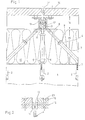
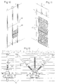
- Fig. 1 is a section of a ventilated facade receiving supporting wall 1 of a building, for example a concrete wall, shown, attached in the dowel 2 to support the facade are.
- Screw bolts 3 of struts 4 are screwed into the dowels 2, which, forming a ball joint, the ball head 5 of the Bolt 3 with spherical cups 6 embrace.
- the threaded spindles run like a hammer trained connection heads 10, which in coupling rings 11, which are held by means of a screw 12 in aluminum risers 13 are held, the legs of which in turn facade panels 14 wear.
- the building is thermally insulated. through glass or rock wool underneath the risers 13 cover the surface of the building as an insulating layer 15. Between this insulating layer 15 and the facade panels 14 an air gap 16 is kept free, the thickness of which, for example, 25 mm can be up to 40 mm, and by ventilation of the Facade panels 14 to keep the insulating layer 15 dry can
- the aluminum shoulder strap 13 of FIG. 1 is divided and by one Plastic web 17 connected to thermally conductive bridges exclude if possible. Furthermore, they are also Brace 4 thermally insulated by either the threaded sockets 7 and / or their threaded spindles 8 at least in some areas are made of plastic. This makes them thermally conductive Bridges are interrupted, which would otherwise be caused by reaching through the insulating layer 15 adversely affect their effectiveness would.
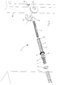
- Fig. 3 is a strut with its connecting elements in so-called exploded view shown.
- the supporting wall 1 has a dowel 2, in the internal thread of the screw bolt 3 can be screwed in with the lock nut 21 can be secured.
- a ball head 5 worked on, which is encompassed by a ball socket 6 and forms a ball joint with it. So that is the strut 4 freely adjustable in its inclination, and the dowel 2 is thus relieved of bending forces.
- the ball pan goes into a threaded sleeve 7 through a longitudinal slot 22nd is divided and delivered spring loaded, so that the Threaded spindle 8 can be inserted into it at any depth.
- the hammer-shaped connecting head 10 is fixed the threaded spindle 8 by insertion into an arc groove 24 two coupling rings 11, the existing between wooden Carrying straps 18 are held on a pin 19.
- the coupling rings for easier mounting 11 not with a hole for the pin 19 to pass through equipped, but with an open through a slot Partial bore, the slot forming two hooks 25.
- the Coupling rings 11 are thus flattened by means of the slot Pin areas slidable and can be turned and Moving corresponding longitudinal grooves of a pin 19 being held.
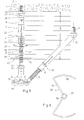
- FIG. 4 Two of the struts shown in FIG. 3 are mounted in FIG. 4 shown.
- the bolts 3 are not shown in here Screwed in dowels, and the threaded sleeves 7 are through Pushing the locking slide 9 under fixing Prestressed against the threaded spindles 8.
- the circular arc groove 24 of the coupling rings 11 are of such a length stated that not only two, but also without further ado three struts 4 could be connected.
- a side Opening the circular arc groove 24 also allows the subsequent Insertion of connection heads. From the through the struts 4 struts reaching beyond the plane can can be connected in the same way by whose connection head bent accordingly, for example by 30 to 50 ° is.
- a development of the invention relates in particular to applied elements to for little different components high quantities each and thus an inexpensive to enable industrial production and rational storage.
- Such an arrangement is intended for both the known Facade types can be used, but also for new facade types own.
- An essential step is already through the Replacement of usual holding elements, for example bending brackets, with Adjustable length struts that both pressure and can also transmit tensile forces.
- Another simplification is achieved if, for example, the threaded sleeves 7 and do not catch the threaded spindles 8 with the usual, for example, catchy, Threads, but with a variety of each as a central collar of circumferential threads.
- the surface of the support wall 1, although in practice one Approaching the plane only within wide tolerances is shown here as Considered level 1.
- the supporting wall 1 contains a dowel 2, in the one essentially designed as a machine screw, for example M8 Bolt 3 with the help of its hexagon socket 28 is screwed in. Otherwise, the screw head is as Ball socket 26 formed which extends in one direction also allow greater inclinations to the swivel opening 27 expanded. In this ball socket 26 one engages at the inner end the threaded sleeve 7 arranged ball 30 as a swivel joint.
- the threaded sleeve 7 is smoothly worked out inside and only has towards the collar 23, for example 25 thread of pitch 0.
- the threaded sleeve 7 is open towards the collar 23 and can be slide easily over the free end of the threaded spindle 8, which has, for example, a 50 thread of pitch 0.
- the strut can facilitate the installation of insulation 4 are folded, for example in the direction of the double arrow 52, the left part arrow by the arrangement of the pivot opening 27 is larger than the partial arrow shown on the right. Further are also swivels about a plane perpendicular to this possible. Once the desired thickness of the insulation material 15 has been reached, so this can easily be clamped on Insulation holder 29 are fixed. Like supervision Such an insulation holder 29 of FIG.
- a bracket 36 in the form of at least a semicircle curved to which, continuing the clamp, pressure bars 37 connect that over diagonally and radially straying Leg 38 to the actual holders of the insulating material 15, the wings 39, lead.
- Such an insulation holder can be relatively easy to apply and adjust in height, especially if the clip formed is inserted, for example a screwdriver widened between the pressure bars 37 becomes.
- an inclined strut 33 is additionally provided, the hollow spherical zone jacket 31 is held in a strut cage 34, the is closed by means of a cage cover 35.
- a strut cage 34 Connected the normal strut 4 and the oblique strut 33, which the latter is shown here in a kind of exploded view, For example, penetrating through a strut cage 34 and cage cover 35 Screw into a corresponding thread of the End piece 32 of the strut 4 is screwed.
- cage with two, three, four or more Recording areas are made and with one, two, three and the like threaded spindles and / or threaded sockets already be equipped, so that the desired supporting structures are modular can be created.
- a FUR plastic dowel ⁇ is shown here 10 mm as an anchor 40 inserted into the supporting wall 1, with 41 denotes an internally threaded anchor FZA-I M8, and is under 42 an injection anchor FI-M / FIM-N M8 listed.
- the corresponding Connection elements are shown in Fig. 8. So can for example, the strut cage 34 with cover 35, containing a ball at the end of a threaded sleeve 7, with the dowel 40 by a Screw 43 are connected, which is a simple dowel screw ⁇ 7 mm.
- a screw 44 designed as a countersunk screw M8.
- FIG. 9 Another example is shown in FIG. 9.
- both tangential and normal forces are two here Oblique struts 33 used with the base of the distance their bolts 3 form a dimensionally stable triangle.
- Strut cage 34 and its cover is still a threaded spindle 8 connected, which is not added to the strut, but only the inclusion of an insulating material holder fixing the insulating material 15 29 serves.
- the threaded sleeves can be made from pipes 10 x 1 mm or 8 x 1 mm, where the respective Ball head can be formed from the sleeve by roll forming or as a short gutter pin with a spherical head with the socket is compressible. It has also proven itself to be at least part of Threaded sleeves and threaded spindles made of plastic, e.g. fiber reinforced polyamide, to manufacture the parts of the Strive to decouple thermally.
- net rods for example net rods 49 of FIG. 10
- net rods 49 of FIG. 10 can be provided be that extend across the steel belts 60. It exists with closed facade types such as plaster base plates, Profile sheets made of steel and / or aluminum, wooden formwork and the possibility of the facade itself as a second Use stabilization axis.
- closed facade types such as plaster base plates, Profile sheets made of steel and / or aluminum, wooden formwork and the possibility of the facade itself as a second Use stabilization axis.
- FIG. 10 shows steel profile belts 60, which is braced by transverse net rods 49 11
- a facade substructure created from net rods 49 represents.
- the struts needed are each indicated by short lines, for example the Steel profile belts 60 of FIG. 10 at the upper end as a fixed axis held by belt triangles extending in vertical planes and the steel profile belt shown in the middle is equipped with four struts as a fixed measuring point, while other belt triangles denoted by "2" shear forces take over and with "1" struts as normal struts Act.
- the configuration of FIG. 11 is corresponding.
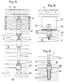
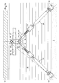
- Figure 12 are a normal strut 46 and two oblique struts 33, each in connection with insulation layers 15, insulation holders 29 and steel profile belts 60 are shown.
- Soft seals 61 not only seal the steel belts 60 against the Facade panels 14, including those between the facade panels 14 joints are formed by stainless steel profiles 64 or Stainless steel tapes 65 sealed.
- a normal strut 46 is shown on the they holding the supporting wall 1 is approximately normal and the distance of the existing wooden straps 18 to the supporting wall 1 selectable certainly. Shown is broken off into the supporting wall 1 inserted dowel 53, the shaft 66 of which is a ball socket 67 picks up a ball by pressing the free opening the ball socket 67 is pivotable, but not extendable, is held.
- the ball not specified here, is on End of a threaded sleeve 7 is provided which, for example. 25 pitch thread has pitch 0 while in it engaging threaded spindle 8, for example, 50 gears of a corresponding Thread of pitch 0.
- the threaded spindle 8 ends in a ball, not shown, which is received and enclosed by a ball socket 67, which is formed on the end of the shaft 66 of a dowel 53.
- a ball socket 67 which is formed on the end of the shaft 66 of a dowel 53.
- the one provided at the upper end of the strut 46 Dowel 53 is used to place it in a pre-machined hole screw existing wooden strap 18, which in turn about means not shown for fixing facade panels 14 is used.
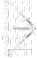
- struts 33 which with the Distance of the dowels 53 carrying them with a congruent triangle form three adjustable-certain side lengths.
- the diagonal struts also pierce an insulating layer 15 and end in balls, which are held in ball sockets 77 of a U-bracket 75 are.
- This bracket 75 is made of a tube that over the yoke area of the bracket is pressed flat and in the middle of the yoke has a bore with which it is by means of a Screw 74 which is in a threaded hole of the bottom 73 of the cross-linking piece 72 is screwed.
- the one at an obtuse angle bent legs 76 of the bracket are to ball sockets 77 pressed, which the balls at the end of the threaded spindles 8th record and closed by pressing their edge area 78 are.
- Such U-bracket 75 allow simple Way to connect two struts to a certain point, and by means of the same screw 74 further U-brackets, even one-sided, be used, so that too not just two diagonal struts here, but three or four Struts can be connected pyramid-like.
- the crosslinking piece 72 is at the lower end by its preferably used, bottom 73 closed and is in the rest formed as a square tube open at the top.
- Each of its Sidewalls has two adjacent bores 48 which appropriately touch each other.
- In the network piece can be in opposite pairs of holes 48th continuous net rods 49 are drawn in; It is also possible to insert short connecting pieces 47 into the holes and over this the free ends of stronger net rods 50 pull. Pinches 51 can be used for pinching 47 and net rods 50 connect properly.
- the facade panels 14 also shown here can be preferably in the area of the crosslinking pieces 72 suitable elements on the connecting piece 47 or net rods Hang up 49, 50.
- FIG. 15 Another normal strut is with its lower one, with the Support wall 1 connected end shown in Fig. 15.
- the bulkhead 1 is a cylindrical hole made in its clear width the diameter of the shaft 66 of the dowel 53 corresponds.
- the dowel is roughly in with a coarse thread Semicircular profile or other profiles provided, and on the free At the end, the diameter of both the shaft 66 decreases as well as the core diameter of the thread.
- the Pitch corresponds to that of the thread of the shaft 66 and their Diameter that of the first thread of smaller diameter is adjusted.
- Figure 15 also shows both simplifications in the Manufacturing as well as ways to reduce the resulting thermal conductance of struts.
- the one with the threaded sleeve 7 broken strut comprises a bolt 69, which with some Is equipped in which sections 70 of the free End of the threaded sleeve 7 are pressed, so that the threaded sleeve 7 can be made from a simple tube.
- the Bolt 69 contains reinforcement at its lower free end or a flange 68, the maximum diameter that exceeds the opening of the ball socket 67.
- To the A reinforcement 68 is injection molded around a ball 84 made of plastic or a corresponding hollow ball is pressed on.
- FIG. 16 shows the upper area of one such Carrying strap 81 connected from metal profile Normal strut.
- Threaded spindle 8 engages in a ball socket 67, which itself continues upwards into a bolt 83, which with a the shoulder strap 81 connected rivet nut 82 engages.
- the threaded spindle 8 upwards continues and ends in a reinforcement 68 that with plastic in Form a ball 84 is overmolded. So here is the one too thermal route to reduce thermal losses interrupted.
Landscapes
- Engineering & Computer Science (AREA)
- Architecture (AREA)
- Civil Engineering (AREA)
- Structural Engineering (AREA)
- Finishing Walls (AREA)
- Joining Of Building Structures In Genera (AREA)
Claims (20)
- Construction présentant au moins une façade, derrière laquelle existe une aération, maintenue devant la face frontale de ladite construction, dont la paroi support est reliée à des pièces d'écartement, qui maintiennent, de préférence de manière réglable, des réseaux de membrures, réalisés à partir de membrures supports et/ou de grillages formés à partir de tubes, disposés devant cette paroi support, des couches d'isolation thermique étant disposées dans les zones entre la paroi support et le réseau de membrures, et le réseau de membrures reprenant des plaques de façades, en maintenant une distance par rapport à ces couches d'isolation, caractérisée en ce qu'on a prévu, comme pièces d'écartement, des tirants (4, 33, 46) à longueur réglable, dont une extrémité est chaque fois reliée de manière articulée, via une articulation à bille (5, 6 ; 84, 67), à une cheville (2, 40, 41, 42, 53) disposée dans la paroi support (1) de la construction et dont l'autre extrémité est chaque fois reliée aux membrures (13, 18, 60, 81) et/ou treillis (49, 50) supportant les éléments (14) de façade.
- Façade selon la revendication 1, caractérisée en ce qu'on a prévu au moins un groupe de deux tirants (4, 33) s'agrippant au même point des membrures support (13, 18, 49, 50, 60, 81), pour reprendre leur poids, lesdits tirants formant un triangle avec la distance par rapport à la cheville (2, 53) qui les fixe, dont la base est essentiellement verticale et en ce qu'on a prévu au moins un groupe de deux tirants (4, 33) s'agrippant à un point commun des membrures support (13, 18) ou du grillage (49, 50), pour reprendre les forces transversales, lesdits tirants formant un triangle avec la distance par rapport à la cheville (2, 53) qui les fixe, dont la base est essentiellement horizontale.
- Façade selon la revendication 1 ou 2, caractérisée en ce que les tirants (4, 33, 46) présentent chaque fois un manchon taraudé (7), qui est divisé longitudinalement par au moins une fente longitudinale (22) sur une longueur partielle dudit manchon et dont les parties ont un effet de ressort, et qui peut être fermé à l'aide d'un élément (collier de verrouillage 9) qui l'entoure autour d'une tige filetée (7) qui s'agrippe dans ledit manchon, ladite tige étant équipée en son extrémité libre d'une bille (84) maintenue de manière à pouvoir pivoter dans un coussinet sphérique (57, 77) d'une pièce de raccord (75, 83).
- Façade selon la revendication 3, caractérisée en ce que les manchons taraudés (6) des tirants (4, 33, 46) se renforcent coniquement vers leur extrémité libre.
- Façade selon la revendication 3 ou 4, caractérisée en ce que les manchons taraudés (6) des tirants (4, 33, 46) présentent, en leur extrémité libre, un bourrelet (23) et/ou une rainure plate devant celui-ci.
- Façade selon au moins une quelconque des revendications 1 à 3, caractérisée en ce que les filetages qui s'agrippent l'un à l'autre du manchon taraudé (7) et de la tige filetée (8) des tirants (4, 33, 46) présentent des filetages courants de pas 0.
- Façade selon au moins une quelconque des revendications 3 à 6, caractérisée en ce que les filetages du manchon taraudé (7) et de la tige filetée (8) des tirants (4, 33, 46) présentent des longueurs différentes.
- Façade selon au moins une quelconque des revendications 1 à 7, caractérisée en ce que les tiges filetées (7) des tirants (4) présentent en leur extrémité libre un oeillet présentant, le cas échéant, des angles.
- Façade selon au moins une quelconque des revendications 1 à 8, caractérisée en ce que les tirants (4) présentent, en au moins une de leurs extrémités, une tête de marteau (10) s'agrippant dans des anneaux de couplage (11).
- Façade selon au moins une quelconque des revendications 1 à 9, caractérisée en ce que les tirants (4, 33, 46) sont équipés aux deux extrémités d'articulations à bille (84, 67).
- Tirant selon au moins une quelconque des revendications 1 à 10, caractérisé en ce que des billes (31) prévues aux extrémités de plus d'un tirant (33) sont maintenues dans une cage à bille (34) présentant plusieurs coussinets à bille et pouvant être fermée à l'aide d'un couvercle en cage (35).
- Façade selon au moins une quelconque des revendications 1 à 11, caractérisée par des étriers (75) présentant deux côtés (76) repliés, en forme de U, réalisés dans un tube, dont la traverse perforée en son centre est comprimée à plat, alors que les extrémités libres des côtés (76) repliés d'un angle obtus, après avoir repris une bille (84) disposée en l'extrémité d'un tirant, sont comprimées à l'endroit où ils débouchent (78) afin de former un coussinet sphérique (77).
- Façade selon au moins une quelconque des revendications 12, caractérisée en ce que les manchons taraudés (7), les tiges filetées (8), les billes (84), les coussinets sphériques (67) et/ou des parties de ceux-ci sont composés de matière synthétique.
- Façade selon au moins une quelconque des revendications 1 à 13, caractérisée en ce que les colliers de verrouillage (9) moulés en matière synthétique présentent une pièce intercalaire métallique opportunément exécutée sous forme de tubulure.
- Façade selon au moins une quelconque des revendications 1 à 14, caractérisée en ce qu'on a réalisé des billes d'articulation (84), prévues en l'extrémité libre des manchons taraudés (7) et/ou des tiges filetées (8), sous forme de pièces de réduction (68) en forme de bride couverte et/ou enrobée sphériquement par extrusion, dont le diamètre est supérieur à la largeur interne du coussinet sphérique (67) qui les reprend.
- Façade selon au moins une quelconque des revendications 1 à 15, caractérisée en ce qu'on a glissé ou enfoncé des boulons (69) dans l'extrémité libre des manchons filetés (7) et en ce que cette extrémité libre (section 70) est enfoncée sur le boulon, de préférence pourvu de rainures.
- Façade selon au moins une quelconque des revendications 1 à 16, caractérisée en ce que des coussinets sphériques (6, 26, 67) entourant des billes (5, 84) sont disposés en l'extrémité libre de vis (3, 45) ou de chevilles (2, 53).
- Façade selon au moins une quelconque des revendications 1 à 17, caractérisée en ce que des vis (3, 45) et/ou des chevilles (53) sont équipées de coussinets de réduction (hexagone 28, couronne 71) pour une prise mécanique d'outils.
- Façade selon au moins une quelconque des revendications 1 à 18, caractérisée en ce que, lors de la fermeture de coussinets sphériques (67), après avoir repris les billes (84), on a enfoncé, de préférence en comprimant son bord libre dans ceux-ci, un coussinet de réduction (couronne 71) pour la prise mécanique d'outils.
- Façade selon au moins une quelconque des revendications 1 à 19, présentant des éléments de fixation de type cheville, pouvant être introduits dans des parois support ou des membrures support, reliés via des articulations à bille à des tirants dont la longueur est réglable, caractérisée en ce que les chevilles (53) présentent une tige (66) cylindrique se rétrécissant en leur extrémité libre, dans laquelle est taraudée un filet grossier avec un diamètre central qui de rétrécit en son extrémité, et avec un ressort (80) plié en forme d'hélice, adaptée à l'extrémité qui se rétrécit du filetage, ledit ressort étant vissé, lors du vissage de la cheville dans un trou préforé de la paroi (1) destinée à la recevoir, sur le filetage en s'élargissant et s'enfonçant dans la paroi du trou.
Applications Claiming Priority (7)
| Application Number | Priority Date | Filing Date | Title |
|---|---|---|---|
| DE29501937U DE29501937U1 (de) | 1995-02-07 | 1995-02-07 | Bauwerk mit hinterlüfteter Fassade und zu deren Montage versehene Strebe |
| DE29501937U | 1995-02-07 | ||
| DE29516664U DE29516664U1 (de) | 1995-02-07 | 1995-10-21 | Bauwerk mit von Distanzstücken gehaltenem Gurtnetz und von diesem getragener, hinterlüfteter Fassade |
| DE29516664U | 1995-10-21 | ||
| DE19547318 | 1995-12-18 | ||
| DE1995147318 DE19547318A1 (de) | 1995-12-18 | 1995-12-18 | Ankerstab zum Einleiten von Zug- und/oder Druckkräften in Baustoffe |
| PCT/EP1996/000508 WO1996024732A1 (fr) | 1995-02-07 | 1996-02-07 | Structure comprenant un reseau de poutres maintenues par des entretoises, et façade aeree par l'arriere soutenue par ladite structure |
Publications (2)
| Publication Number | Publication Date |
|---|---|
| EP0808397A1 EP0808397A1 (fr) | 1997-11-26 |
| EP0808397B1 true EP0808397B1 (fr) | 1999-06-02 |
Family
ID=27215752
Family Applications (1)
| Application Number | Title | Priority Date | Filing Date |
|---|---|---|---|
| EP96902985A Expired - Lifetime EP0808397B1 (fr) | 1995-02-07 | 1996-02-07 | Structure comprenant un reseau de poutres maintenues par des entretoises, et facade aeree par l'arriere soutenue par ladite structure |
Country Status (2)
| Country | Link |
|---|---|
| EP (1) | EP0808397B1 (fr) |
| WO (1) | WO1996024732A1 (fr) |
Cited By (1)
| Publication number | Priority date | Publication date | Assignee | Title |
|---|---|---|---|---|
| DE202012001461U1 (de) | 2012-02-15 | 2012-03-14 | Mcon Gmbh | Halterungsanordnung |
Families Citing this family (9)
| Publication number | Priority date | Publication date | Assignee | Title |
|---|---|---|---|---|
| DE29615166U1 (de) * | 1996-08-31 | 1996-10-17 | Houben, Dietmar, 42107 Wuppertal | Fassadenunterkonstruktion |
| DE19945197C1 (de) | 1999-09-21 | 2001-07-05 | Dorma Gmbh & Co Kg | Befestigungsvorrichtung für eine Glasscheibe |
| FR2922923A1 (fr) * | 2007-10-30 | 2009-05-01 | Internat Fixing Systems Sarl | Systeme integre de reprise des efforts lateraux paralleles au plan d'un revetement de facade |
| ITBG20100021A1 (it) * | 2010-04-22 | 2010-07-22 | Marco Gatti | Rivestimento a cappotto per l'isolameto termoacustico di edifici con corazza impermeabile ad altissima resistenza agli agenti atmosferici e con doppio fissaggio chimico meccanico. |
| DE102010017020A1 (de) * | 2010-05-19 | 2011-11-24 | Fischerwerke Gmbh & Co. Kg | Abstandshalter zur Befestigung eines Gegenstandes |
| HU229785B1 (en) | 2010-12-17 | 2014-07-28 | Gabor Fazakas | Fastening unit with ball joint for mounting thermal insulation |
| DE102011102510A1 (de) * | 2011-05-26 | 2012-11-29 | Sfs Intec Holding Ag | System zum Befestigen einer Dämmfassade und dafür vorgesehener Befestiger |
| FR3018837A1 (fr) * | 2014-03-21 | 2015-09-25 | Gen Innovation Ind France | Connecteur de panneaux exterieurs a une ossature |
| DE102018131789A1 (de) * | 2018-12-11 | 2020-06-18 | Metal Envelope Gmbh | Halterung zur Befestigung eines Fassadenbekleidungselements an einer Tragstruktur |
Family Cites Families (5)
| Publication number | Priority date | Publication date | Assignee | Title |
|---|---|---|---|---|
| DE1274326B (de) * | 1966-09-10 | 1968-08-01 | Fischer Artur | Halterung aus Kunststoff fuer eine Wandverkleidung |
| DE3927653A1 (de) * | 1989-08-22 | 1991-03-14 | Danz Robert | Halterung fuer eine biegemomentfreie lagerung von wand- oder deckenplatten |
| DE4340508C2 (de) * | 1993-11-27 | 2002-03-28 | Seele Gmbh | Haltevorrichtung für Fassaden- und Dachplatten |
| DE4340509B4 (de) * | 1993-11-27 | 2004-11-18 | Seele Gmbh & Co. Kg | Haltevorrichtung für Fassaden- und Dachplatten, insbesondere Glasscheiben |
| DE9318862U1 (de) * | 1993-12-10 | 1995-04-06 | Danz, Robert, Dipl.-Ing., 71101 Schönaich | Halterung für eine punktförmige, biegemomentfreie Lagerung von Mehrfach-Isolierglasscheiben |
-
1996
- 1996-02-07 WO PCT/EP1996/000508 patent/WO1996024732A1/fr not_active Ceased
- 1996-02-07 EP EP96902985A patent/EP0808397B1/fr not_active Expired - Lifetime
Cited By (2)
| Publication number | Priority date | Publication date | Assignee | Title |
|---|---|---|---|---|
| DE202012001461U1 (de) | 2012-02-15 | 2012-03-14 | Mcon Gmbh | Halterungsanordnung |
| DE202012008637U1 (de) | 2012-02-15 | 2012-09-21 | Mcon Gmbh | Halterungsanordnung |
Also Published As
| Publication number | Publication date |
|---|---|
| EP0808397A1 (fr) | 1997-11-26 |
| WO1996024732A1 (fr) | 1996-08-15 |
Similar Documents
| Publication | Publication Date | Title |
|---|---|---|
| EP3384105B1 (fr) | Dispositif de support en métal servant à suspendre un échafaudage suspendu ou une autre structure suspendue | |
| DE102005014900A1 (de) | Verbundanker zum Verbinden mindestens zweier Bauelemente und System von miteinander verbundenen Bauelementen | |
| AT6961U2 (de) | Verstell- und fixiervorrichtung | |
| EP0808397B1 (fr) | Structure comprenant un reseau de poutres maintenues par des entretoises, et facade aeree par l'arriere soutenue par ladite structure | |
| EP0333772B1 (fr) | Systeme modulaire de construction | |
| EP2236693B1 (fr) | Support à isolation thermique pour éléments de revêtement | |
| DE102007037271A1 (de) | Vorrichtung zum Befestigen von plattenartigen Verkleidungselementen | |
| WO2019081546A1 (fr) | Structure porteuse pivotante pour des modules solaires ou photovoltaïques, installation avec plusieurs modules solaires ou photovoltaïques ainsi que procédé de montage d'une telle installation | |
| DE19737515C2 (de) | Vorrichtung zur Befestigung von Bauteilen an und im Abstand zu einem Tragwerk, insbesondere von Längsprofilen an und im Abstand zu einer Bauwerkswand und dafür geeigneter Abstandhalter | |
| DE102011115772A1 (de) | Gerüstanker mit Gerüstabstützung für Wärmedämmverbundsysteme | |
| EP0022070B1 (fr) | Etai tubulaire pour petites constructions avec au moins un profil de raccordement qui lui est associé de façon détachable | |
| DE2924108A1 (de) | Tragblock fuer fassadenverkleidungen | |
| DE1484009A1 (de) | Haus in Fertigbauweise,plattenfoermiges Bauelement zur Herstellung dieses Hauses,Zwischenstueck zur Verbindung der Bauelemente und Verfahren zur Herstellung des Hauses | |
| DE29516664U1 (de) | Bauwerk mit von Distanzstücken gehaltenem Gurtnetz und von diesem getragener, hinterlüfteter Fassade | |
| EP1088943A2 (fr) | Support de montage avec accessoire de montage | |
| DE3328232C2 (de) | Raumfachwerk | |
| AT510059B1 (de) | Verbindungsvorrichtung zum verbinden von miteinander zu verbindenden gegenständen sowie konstruktionselement und verwendung | |
| EP0805281A1 (fr) | Dispositif de fixation avec deux profilés en forme de barre | |
| EP0052158A1 (fr) | Bloc-support pour revêtements de façades | |
| DE3128505A1 (de) | Vorrichtung zur knotenverbindung hoelzerner fachwerksstaebe | |
| DE102017101938A1 (de) | Hängezuganker | |
| DE2711403C2 (de) | Deckentragwerk | |
| EP1631727A1 (fr) | Systeme d'elements de construction assembles | |
| DD296135A5 (de) | Verbindungstraeger zur befestigung von rahmenkonstruktionen | |
| DE1905726U (de) | Vorrichtung zum einregulieren und/oder festspannen von bauwerksteilen. |
Legal Events
| Date | Code | Title | Description |
|---|---|---|---|
| PUAI | Public reference made under article 153(3) epc to a published international application that has entered the european phase |
Free format text: ORIGINAL CODE: 0009012 |
|
| 17P | Request for examination filed |
Effective date: 19970801 |
|
| AK | Designated contracting states |
Kind code of ref document: A1 Designated state(s): BE CH DE FR GB IT LI NL SE |
|
| GRAG | Despatch of communication of intention to grant |
Free format text: ORIGINAL CODE: EPIDOS AGRA |
|
| 17Q | First examination report despatched |
Effective date: 19980820 |
|
| GRAG | Despatch of communication of intention to grant |
Free format text: ORIGINAL CODE: EPIDOS AGRA |
|
| GRAH | Despatch of communication of intention to grant a patent |
Free format text: ORIGINAL CODE: EPIDOS IGRA |
|
| GRAH | Despatch of communication of intention to grant a patent |
Free format text: ORIGINAL CODE: EPIDOS IGRA |
|
| GRAA | (expected) grant |
Free format text: ORIGINAL CODE: 0009210 |
|
| AK | Designated contracting states |
Kind code of ref document: B1 Designated state(s): BE CH DE FR GB IT LI NL SE |
|
| REG | Reference to a national code |
Ref country code: CH Ref legal event code: EP |
|
| REF | Corresponds to: |
Ref document number: 59602089 Country of ref document: DE Date of ref document: 19990708 |
|
| ITF | It: translation for a ep patent filed | ||
| REG | Reference to a national code |
Ref country code: CH Ref legal event code: NV Representative=s name: ULRICH BALLMER, BRIGITTE BALLMER PATENTANWAELTE |
|
| GBT | Gb: translation of ep patent filed (gb section 77(6)(a)/1977) |
Effective date: 19990812 |
|
| ET | Fr: translation filed | ||
| PLBE | No opposition filed within time limit |
Free format text: ORIGINAL CODE: 0009261 |
|
| STAA | Information on the status of an ep patent application or granted ep patent |
Free format text: STATUS: NO OPPOSITION FILED WITHIN TIME LIMIT |
|
| 26N | No opposition filed | ||
| REG | Reference to a national code |
Ref country code: GB Ref legal event code: IF02 |
|
| PGFP | Annual fee paid to national office [announced via postgrant information from national office to epo] |
Ref country code: CH Payment date: 20120221 Year of fee payment: 17 Ref country code: FR Payment date: 20120227 Year of fee payment: 17 |
|
| PGFP | Annual fee paid to national office [announced via postgrant information from national office to epo] |
Ref country code: GB Payment date: 20120221 Year of fee payment: 17 Ref country code: SE Payment date: 20120217 Year of fee payment: 17 Ref country code: BE Payment date: 20120329 Year of fee payment: 17 Ref country code: IT Payment date: 20120227 Year of fee payment: 17 |
|
| PGFP | Annual fee paid to national office [announced via postgrant information from national office to epo] |
Ref country code: NL Payment date: 20120228 Year of fee payment: 17 |
|
| PGFP | Annual fee paid to national office [announced via postgrant information from national office to epo] |
Ref country code: DE Payment date: 20130227 Year of fee payment: 18 |
|
| BERE | Be: lapsed |
Owner name: *HOFFMANN MANFRED Effective date: 20130228 |
|
| REG | Reference to a national code |
Ref country code: NL Ref legal event code: V1 Effective date: 20130901 |
|
| REG | Reference to a national code |
Ref country code: CH Ref legal event code: PL |
|
| REG | Reference to a national code |
Ref country code: SE Ref legal event code: EUG |
|
| GBPC | Gb: european patent ceased through non-payment of renewal fee |
Effective date: 20130207 |
|
| PG25 | Lapsed in a contracting state [announced via postgrant information from national office to epo] |
Ref country code: CH Free format text: LAPSE BECAUSE OF NON-PAYMENT OF DUE FEES Effective date: 20130228 Ref country code: NL Free format text: LAPSE BECAUSE OF NON-PAYMENT OF DUE FEES Effective date: 20130901 Ref country code: SE Free format text: LAPSE BECAUSE OF NON-PAYMENT OF DUE FEES Effective date: 20130208 Ref country code: LI Free format text: LAPSE BECAUSE OF NON-PAYMENT OF DUE FEES Effective date: 20130228 |
|
| REG | Reference to a national code |
Ref country code: FR Ref legal event code: ST Effective date: 20131031 |
|
| PG25 | Lapsed in a contracting state [announced via postgrant information from national office to epo] |
Ref country code: IT Free format text: LAPSE BECAUSE OF NON-PAYMENT OF DUE FEES Effective date: 20130207 |
|
| PG25 | Lapsed in a contracting state [announced via postgrant information from national office to epo] |
Ref country code: FR Free format text: LAPSE BECAUSE OF NON-PAYMENT OF DUE FEES Effective date: 20130228 Ref country code: BE Free format text: LAPSE BECAUSE OF NON-PAYMENT OF DUE FEES Effective date: 20130228 Ref country code: GB Free format text: LAPSE BECAUSE OF NON-PAYMENT OF DUE FEES Effective date: 20130207 |
|
| REG | Reference to a national code |
Ref country code: DE Ref legal event code: R119 Ref document number: 59602089 Country of ref document: DE |
|
| REG | Reference to a national code |
Ref country code: DE Ref legal event code: R119 Ref document number: 59602089 Country of ref document: DE Effective date: 20140902 |
|
| PG25 | Lapsed in a contracting state [announced via postgrant information from national office to epo] |
Ref country code: DE Free format text: LAPSE BECAUSE OF NON-PAYMENT OF DUE FEES Effective date: 20140902 |