EP0807513A1 - Vorrichtung zum Verbinden eines Aufreissstreifens mit einer Folienbahn - Google Patents
Vorrichtung zum Verbinden eines Aufreissstreifens mit einer Folienbahn Download PDFInfo
- Publication number
- EP0807513A1 EP0807513A1 EP97107430A EP97107430A EP0807513A1 EP 0807513 A1 EP0807513 A1 EP 0807513A1 EP 97107430 A EP97107430 A EP 97107430A EP 97107430 A EP97107430 A EP 97107430A EP 0807513 A1 EP0807513 A1 EP 0807513A1
- Authority
- EP
- European Patent Office
- Prior art keywords
- rollers
- sealing
- counter
- web
- film web
- Prior art date
- Legal status (The legal status is an assumption and is not a legal conclusion. Google has not performed a legal analysis and makes no representation as to the accuracy of the status listed.)
- Granted
Links
- 238000007789 sealing Methods 0.000 claims abstract description 64
- 239000000463 material Substances 0.000 claims abstract description 18
- 238000004806 packaging method and process Methods 0.000 claims description 6
- 238000010438 heat treatment Methods 0.000 claims description 5
- 229920001296 polysiloxane Polymers 0.000 claims description 2
- 239000004020 conductor Substances 0.000 claims 2
- 230000005855 radiation Effects 0.000 abstract description 4
- 229920006280 packaging film Polymers 0.000 abstract 1
- 239000012785 packaging film Substances 0.000 abstract 1
- 229920000298 Cellophane Polymers 0.000 description 2
- 235000019504 cigarettes Nutrition 0.000 description 2
- 210000000056 organ Anatomy 0.000 description 2
- 239000002985 plastic film Substances 0.000 description 2
- 229920006255 plastic film Polymers 0.000 description 2
- 238000003892 spreading Methods 0.000 description 2
- 239000000853 adhesive Substances 0.000 description 1
- 238000004026 adhesive bonding Methods 0.000 description 1
- 230000001070 adhesive effect Effects 0.000 description 1
- 239000011248 coating agent Substances 0.000 description 1
- 238000000576 coating method Methods 0.000 description 1
- 239000013013 elastic material Substances 0.000 description 1
- 238000004519 manufacturing process Methods 0.000 description 1
- 239000007769 metal material Substances 0.000 description 1
- 238000000034 method Methods 0.000 description 1
- 230000002093 peripheral effect Effects 0.000 description 1
- 238000000926 separation method Methods 0.000 description 1
- 230000001360 synchronised effect Effects 0.000 description 1
Images


Classifications
-
- B—PERFORMING OPERATIONS; TRANSPORTING
- B29—WORKING OF PLASTICS; WORKING OF SUBSTANCES IN A PLASTIC STATE IN GENERAL
- B29C—SHAPING OR JOINING OF PLASTICS; SHAPING OF MATERIAL IN A PLASTIC STATE, NOT OTHERWISE PROVIDED FOR; AFTER-TREATMENT OF THE SHAPED PRODUCTS, e.g. REPAIRING
- B29C65/00—Joining or sealing of preformed parts, e.g. welding of plastics materials; Apparatus therefor
- B29C65/02—Joining or sealing of preformed parts, e.g. welding of plastics materials; Apparatus therefor by heating, with or without pressure
- B29C65/18—Joining or sealing of preformed parts, e.g. welding of plastics materials; Apparatus therefor by heating, with or without pressure using heated tools
- B29C65/24—Joining or sealing of preformed parts, e.g. welding of plastics materials; Apparatus therefor by heating, with or without pressure using heated tools characterised by the means for heating the tool
- B29C65/30—Electrical means
- B29C65/305—Electrical means involving the use of cartridge heaters
-
- B—PERFORMING OPERATIONS; TRANSPORTING
- B29—WORKING OF PLASTICS; WORKING OF SUBSTANCES IN A PLASTIC STATE IN GENERAL
- B29C—SHAPING OR JOINING OF PLASTICS; SHAPING OF MATERIAL IN A PLASTIC STATE, NOT OTHERWISE PROVIDED FOR; AFTER-TREATMENT OF THE SHAPED PRODUCTS, e.g. REPAIRING
- B29C66/00—General aspects of processes or apparatus for joining preformed parts
- B29C66/01—General aspects dealing with the joint area or with the area to be joined
- B29C66/05—Particular design of joint configurations
- B29C66/10—Particular design of joint configurations particular design of the joint cross-sections
- B29C66/11—Joint cross-sections comprising a single joint-segment, i.e. one of the parts to be joined comprising a single joint-segment in the joint cross-section
- B29C66/112—Single lapped joints
- B29C66/1122—Single lap to lap joints, i.e. overlap joints
-
- B—PERFORMING OPERATIONS; TRANSPORTING
- B29—WORKING OF PLASTICS; WORKING OF SUBSTANCES IN A PLASTIC STATE IN GENERAL
- B29C—SHAPING OR JOINING OF PLASTICS; SHAPING OF MATERIAL IN A PLASTIC STATE, NOT OTHERWISE PROVIDED FOR; AFTER-TREATMENT OF THE SHAPED PRODUCTS, e.g. REPAIRING
- B29C66/00—General aspects of processes or apparatus for joining preformed parts
- B29C66/40—General aspects of joining substantially flat articles, e.g. plates, sheets or web-like materials; Making flat seams in tubular or hollow articles; Joining single elements to substantially flat surfaces
- B29C66/47—Joining single elements to sheets, plates or other substantially flat surfaces
- B29C66/472—Joining single elements to sheets, plates or other substantially flat surfaces said single elements being substantially flat
- B29C66/4722—Fixing strips to surfaces other than edge faces
-
- B—PERFORMING OPERATIONS; TRANSPORTING
- B29—WORKING OF PLASTICS; WORKING OF SUBSTANCES IN A PLASTIC STATE IN GENERAL
- B29C—SHAPING OR JOINING OF PLASTICS; SHAPING OF MATERIAL IN A PLASTIC STATE, NOT OTHERWISE PROVIDED FOR; AFTER-TREATMENT OF THE SHAPED PRODUCTS, e.g. REPAIRING
- B29C66/00—General aspects of processes or apparatus for joining preformed parts
- B29C66/80—General aspects of machine operations or constructions and parts thereof
- B29C66/82—Pressure application arrangements, e.g. transmission or actuating mechanisms for joining tools or clamps
- B29C66/822—Transmission mechanisms
- B29C66/8221—Scissor or lever mechanisms, i.e. involving a pivot point
-
- B—PERFORMING OPERATIONS; TRANSPORTING
- B29—WORKING OF PLASTICS; WORKING OF SUBSTANCES IN A PLASTIC STATE IN GENERAL
- B29C—SHAPING OR JOINING OF PLASTICS; SHAPING OF MATERIAL IN A PLASTIC STATE, NOT OTHERWISE PROVIDED FOR; AFTER-TREATMENT OF THE SHAPED PRODUCTS, e.g. REPAIRING
- B29C66/00—General aspects of processes or apparatus for joining preformed parts
- B29C66/80—General aspects of machine operations or constructions and parts thereof
- B29C66/83—General aspects of machine operations or constructions and parts thereof characterised by the movement of the joining or pressing tools
- B29C66/834—General aspects of machine operations or constructions and parts thereof characterised by the movement of the joining or pressing tools moving with the parts to be joined
- B29C66/8341—Roller, cylinder or drum types; Band or belt types; Ball types
- B29C66/83411—Roller, cylinder or drum types
- B29C66/83413—Roller, cylinder or drum types cooperating rollers, cylinders or drums
-
- B—PERFORMING OPERATIONS; TRANSPORTING
- B29—WORKING OF PLASTICS; WORKING OF SUBSTANCES IN A PLASTIC STATE IN GENERAL
- B29C—SHAPING OR JOINING OF PLASTICS; SHAPING OF MATERIAL IN A PLASTIC STATE, NOT OTHERWISE PROVIDED FOR; AFTER-TREATMENT OF THE SHAPED PRODUCTS, e.g. REPAIRING
- B29C66/00—General aspects of processes or apparatus for joining preformed parts
- B29C66/80—General aspects of machine operations or constructions and parts thereof
- B29C66/83—General aspects of machine operations or constructions and parts thereof characterised by the movement of the joining or pressing tools
- B29C66/834—General aspects of machine operations or constructions and parts thereof characterised by the movement of the joining or pressing tools moving with the parts to be joined
- B29C66/8341—Roller, cylinder or drum types; Band or belt types; Ball types
- B29C66/83411—Roller, cylinder or drum types
- B29C66/83417—Roller, cylinder or drum types said rollers, cylinders or drums being hollow
-
- B—PERFORMING OPERATIONS; TRANSPORTING
- B29—WORKING OF PLASTICS; WORKING OF SUBSTANCES IN A PLASTIC STATE IN GENERAL
- B29C—SHAPING OR JOINING OF PLASTICS; SHAPING OF MATERIAL IN A PLASTIC STATE, NOT OTHERWISE PROVIDED FOR; AFTER-TREATMENT OF THE SHAPED PRODUCTS, e.g. REPAIRING
- B29C66/00—General aspects of processes or apparatus for joining preformed parts
- B29C66/80—General aspects of machine operations or constructions and parts thereof
- B29C66/87—Auxiliary operations or devices
- B29C66/874—Safety measures or devices
- B29C66/8744—Preventing overheating of the parts to be joined, e.g. if the machine stops or slows down
- B29C66/87443—Preventing overheating of the parts to be joined, e.g. if the machine stops or slows down by withdrawing the heating tools
-
- B—PERFORMING OPERATIONS; TRANSPORTING
- B29—WORKING OF PLASTICS; WORKING OF SUBSTANCES IN A PLASTIC STATE IN GENERAL
- B29C—SHAPING OR JOINING OF PLASTICS; SHAPING OF MATERIAL IN A PLASTIC STATE, NOT OTHERWISE PROVIDED FOR; AFTER-TREATMENT OF THE SHAPED PRODUCTS, e.g. REPAIRING
- B29C66/00—General aspects of processes or apparatus for joining preformed parts
- B29C66/80—General aspects of machine operations or constructions and parts thereof
- B29C66/87—Auxiliary operations or devices
- B29C66/876—Maintenance or cleaning
-
- B—PERFORMING OPERATIONS; TRANSPORTING
- B29—WORKING OF PLASTICS; WORKING OF SUBSTANCES IN A PLASTIC STATE IN GENERAL
- B29C—SHAPING OR JOINING OF PLASTICS; SHAPING OF MATERIAL IN A PLASTIC STATE, NOT OTHERWISE PROVIDED FOR; AFTER-TREATMENT OF THE SHAPED PRODUCTS, e.g. REPAIRING
- B29C65/00—Joining or sealing of preformed parts, e.g. welding of plastics materials; Apparatus therefor
- B29C65/02—Joining or sealing of preformed parts, e.g. welding of plastics materials; Apparatus therefor by heating, with or without pressure
- B29C65/18—Joining or sealing of preformed parts, e.g. welding of plastics materials; Apparatus therefor by heating, with or without pressure using heated tools
- B29C65/24—Joining or sealing of preformed parts, e.g. welding of plastics materials; Apparatus therefor by heating, with or without pressure using heated tools characterised by the means for heating the tool
- B29C65/245—Joining or sealing of preformed parts, e.g. welding of plastics materials; Apparatus therefor by heating, with or without pressure using heated tools characterised by the means for heating the tool the heat transfer being achieved contactless, e.g. by radiation
-
- B—PERFORMING OPERATIONS; TRANSPORTING
- B29—WORKING OF PLASTICS; WORKING OF SUBSTANCES IN A PLASTIC STATE IN GENERAL
- B29C—SHAPING OR JOINING OF PLASTICS; SHAPING OF MATERIAL IN A PLASTIC STATE, NOT OTHERWISE PROVIDED FOR; AFTER-TREATMENT OF THE SHAPED PRODUCTS, e.g. REPAIRING
- B29C66/00—General aspects of processes or apparatus for joining preformed parts
- B29C66/70—General aspects of processes or apparatus for joining preformed parts characterised by the composition, physical properties or the structure of the material of the parts to be joined; Joining with non-plastics material
- B29C66/71—General aspects of processes or apparatus for joining preformed parts characterised by the composition, physical properties or the structure of the material of the parts to be joined; Joining with non-plastics material characterised by the composition of the plastics material of the parts to be joined
-
- B—PERFORMING OPERATIONS; TRANSPORTING
- B29—WORKING OF PLASTICS; WORKING OF SUBSTANCES IN A PLASTIC STATE IN GENERAL
- B29C—SHAPING OR JOINING OF PLASTICS; SHAPING OF MATERIAL IN A PLASTIC STATE, NOT OTHERWISE PROVIDED FOR; AFTER-TREATMENT OF THE SHAPED PRODUCTS, e.g. REPAIRING
- B29C66/00—General aspects of processes or apparatus for joining preformed parts
- B29C66/80—General aspects of machine operations or constructions and parts thereof
- B29C66/81—General aspects of the pressing elements, i.e. the elements applying pressure on the parts to be joined in the area to be joined, e.g. the welding jaws or clamps
- B29C66/814—General aspects of the pressing elements, i.e. the elements applying pressure on the parts to be joined in the area to be joined, e.g. the welding jaws or clamps characterised by the design of the pressing elements, e.g. of the welding jaws or clamps
- B29C66/8145—General aspects of the pressing elements, i.e. the elements applying pressure on the parts to be joined in the area to be joined, e.g. the welding jaws or clamps characterised by the design of the pressing elements, e.g. of the welding jaws or clamps characterised by the constructional aspects of the pressing elements, e.g. of the welding jaws or clamps
- B29C66/81463—General aspects of the pressing elements, i.e. the elements applying pressure on the parts to be joined in the area to be joined, e.g. the welding jaws or clamps characterised by the design of the pressing elements, e.g. of the welding jaws or clamps characterised by the constructional aspects of the pressing elements, e.g. of the welding jaws or clamps comprising a plurality of single pressing elements, e.g. a plurality of sonotrodes, or comprising a plurality of single counter-pressing elements, e.g. a plurality of anvils, said plurality of said single elements being suitable for making a single joint
- B29C66/81465—General aspects of the pressing elements, i.e. the elements applying pressure on the parts to be joined in the area to be joined, e.g. the welding jaws or clamps characterised by the design of the pressing elements, e.g. of the welding jaws or clamps characterised by the constructional aspects of the pressing elements, e.g. of the welding jaws or clamps comprising a plurality of single pressing elements, e.g. a plurality of sonotrodes, or comprising a plurality of single counter-pressing elements, e.g. a plurality of anvils, said plurality of said single elements being suitable for making a single joint one placed behind the other in a single row in the feed direction
-
- B—PERFORMING OPERATIONS; TRANSPORTING
- B29—WORKING OF PLASTICS; WORKING OF SUBSTANCES IN A PLASTIC STATE IN GENERAL
- B29L—INDEXING SCHEME ASSOCIATED WITH SUBCLASS B29C, RELATING TO PARTICULAR ARTICLES
- B29L2031/00—Other particular articles
- B29L2031/712—Containers; Packaging elements or accessories, Packages
- B29L2031/7162—Boxes, cartons, cases
-
- B—PERFORMING OPERATIONS; TRANSPORTING
- B29—WORKING OF PLASTICS; WORKING OF SUBSTANCES IN A PLASTIC STATE IN GENERAL
- B29L—INDEXING SCHEME ASSOCIATED WITH SUBCLASS B29C, RELATING TO PARTICULAR ARTICLES
- B29L2031/00—Other particular articles
- B29L2031/7414—Smokers'' requisites, e.g. pipe cleaners
- B29L2031/7416—Smokers'' requisites, e.g. pipe cleaners for cigars or cigarettes
-
- Y—GENERAL TAGGING OF NEW TECHNOLOGICAL DEVELOPMENTS; GENERAL TAGGING OF CROSS-SECTIONAL TECHNOLOGIES SPANNING OVER SEVERAL SECTIONS OF THE IPC; TECHNICAL SUBJECTS COVERED BY FORMER USPC CROSS-REFERENCE ART COLLECTIONS [XRACs] AND DIGESTS
- Y10—TECHNICAL SUBJECTS COVERED BY FORMER USPC
- Y10T—TECHNICAL SUBJECTS COVERED BY FORMER US CLASSIFICATION
- Y10T156/00—Adhesive bonding and miscellaneous chemical manufacture
- Y10T156/17—Surface bonding means and/or assemblymeans with work feeding or handling means
- Y10T156/1702—For plural parts or plural areas of single part
- Y10T156/1712—Indefinite or running length work
- Y10T156/1739—Webs of different width, longitudinally aligned
-
- Y—GENERAL TAGGING OF NEW TECHNOLOGICAL DEVELOPMENTS; GENERAL TAGGING OF CROSS-SECTIONAL TECHNOLOGIES SPANNING OVER SEVERAL SECTIONS OF THE IPC; TECHNICAL SUBJECTS COVERED BY FORMER USPC CROSS-REFERENCE ART COLLECTIONS [XRACs] AND DIGESTS
- Y10—TECHNICAL SUBJECTS COVERED BY FORMER USPC
- Y10T—TECHNICAL SUBJECTS COVERED BY FORMER US CLASSIFICATION
- Y10T156/00—Adhesive bonding and miscellaneous chemical manufacture
- Y10T156/17—Surface bonding means and/or assemblymeans with work feeding or handling means
- Y10T156/1702—For plural parts or plural areas of single part
- Y10T156/1712—Indefinite or running length work
- Y10T156/1741—Progressive continuous bonding press [e.g., roll couples]
Definitions
- the invention relates to a device for connecting a continuously supplied material strip, in particular a tear strip, with a continuously conveyed material web, in particular a film web, for producing blanks for packaging wrappings with tear strips, the material strip and the material web being connectable to one another by heat and pressure .
- Packaging is often provided with an outer covering made of thin plastic film or cellophane film. This is removed with the help of a tear strip when the packaging is put into use.
- cigarette packs are provided with a wrapping which can be destroyed by a tear strip running all around.
- the tear strip is usually applied continuously to the likewise continuous film web and connected to it by gluing or thermal sealing.
- the tear strip is provided with an adhesive which can be activated by heat and pressure. The connection the tear strip with the film web is therefore time-consuming and requires special equipment.
- the invention has for its object to improve the application of a strip of material, in particular a tear strip, to a film web using heat and pressure, in that the connection takes place reliably even at higher working speeds.
- the device according to the invention is characterized in that the pressure and sealing members are heated sealing rolls which are predominantly or exclusively indirectly heated, in particular by radiant heat.
- the materials to be bonded to one another namely the film web and the tear strip arranged on it in the correct position, are continuously conveyed between pressure rollers and counter pressure rollers, at least the pressure rollers being heated.
- three indirectly heated pressure rollers are successively positioned in the conveying direction of the material web, and three counter pressure rollers are positioned on the opposite side thereof.
- a special feature of the invention is that additional (radiation) heat is transferred to the sealing rolls and additionally to the material to be connected, that is to say tear strips and material web.
- thin-walled webs are arranged as heat transfer elements, which extend between the sealing rollers, follow their contour and end at a minimal distance from the material web or the tear strip. These webs are (co-) heated by the housing. The webs transfer radiant heat to the material web and the tear strip.
- Fig. 1 shows a film unit as part of a packaging machine.
- a film web 10 is continuously drawn off from a bobbin 11 and guided over a multiplicity of deflection and control rollers.
- a tear strip 12, 13 is placed against the film web 10 during continuous transport and, in the area of a sealing station 14, is also connected to the film web 10 during continuous transport by the application of heat and pressure.
- the unit consisting of film web 10 and tear strips 12, 13 is fed to the packaging machine or a separating unit for separating blanks for the outer wrapping.
- a special feature of the device shown in Fig. 1 is that it is designed for two-lane operation.
- the film web 10 drawn off from the bobbin 11 has a double width.
- the film web 10 is divided into two half-width film webs running side by side by means of a central longitudinal section.
- the two film webs 10 running side by side are in the area of a spreading station 16 deflected by spreading rollers 17 so that the two film webs 10 are transported parallel at a distance from each other.
- Each of the film webs 10 is assigned a tear strip 12, 13. These are subtracted from separate bobbins 18, 19. In the area of a merging roller 20, which is also a deflecting roller for the two film webs 10, the tear strips 12 and 13 are applied to the associated film webs 10 running side by side.
- Both film webs 10 with tear strips 12, 13 lying against the pack are then fed to the sealing station 14 running side by side. There, each film web 10 with tear strips 12, 13 is assigned a sealing unit 21. Each of the synchronous, continuously conveyed film webs 10 is connected to the tear-open strip 12, 13 by a sealing unit 21. Following the sealing station 14, two film webs 10, each with a sealed tear strip 12, 13, are transported in parallel and sent for further processing.
- the tear strips 12, 13 are designed or provided with a coating which ensures a durable connection to the film web 10 when heat and pressure are applied.
- the sealing unit 21 is designed such that heat and pressure are continuously applied to the film webs 10 or to the tear strips 12, 13 during the continuous transport of the film webs 10.
- the sealing unit 21 is effective in the region of an upright strand 22 of the film webs 10 and tear strips 12, 13.
- a plurality of sealing rollers 23, 24, 25 which follow one another in the longitudinal direction of the film web 10 act on film web 10 and tear strips 12, 13.
- three sealing rollers 23, 24, 25 are positioned one above the other on a common, upright carrier 26.
- the sealing rollers 23, 24, 25 rest in the area of the tear strips 12, 13 with the transfer of pressure to the tear strips 12, 13 and thus indirectly to the film webs 10.
- Counter-pressure elements are positioned on the side of the film web 10 opposite the sealing rollers 23..25, namely (three) counter rollers 27, 28, 29.
- the counter rollers 27..29 are also mounted on a common holder 30.
- the counter rollers 27..29 are each mounted exactly opposite the sealing rollers 23..25.
- Sealing rolls 23..25 and counter rolls 27..29 are driven according to the conveying speed of the film web 10, are rotated by the latter as a result of the conveying movement.
- the sealing rollers 23..25 are heated so that the heat is also transmitted through the sealing rollers 23..25 for printing.
- indirect heating of the sealing rollers 23.25 is provided, in particular via radiant heat.
- the carrier 26 is designed as a housing 31 which almost completely surrounds the sealing rollers 23..25, namely except for small areas or openings 32 for the passage of sealing surfaces of the sealing rollers 23..25 in the region of the film web 10.
- the housing 31 is directly heated, in the present case by a heating cartridge 33 extending in the longitudinal direction. This is positioned in a bore 34 which extends on the side opposite the film web 10 in the housing 31 directly next to the peripheral surfaces of the sealing rollers 23.25.
- the housing 31 thus heated transfers the heat to the sealing rollers 23..25.
- the heating cartridge 33 is provided with a connection 35 for electrical lines.
- the housing 31 for the sealing rollers 23..25 is designed in a special way such that (radiation) heat is transmitted from the housing 31 directly to the film web 10 or the tear strips 12, 13.
- the housing 31 consists of two parallel longitudinal walls 36, 37, in which the sealing rollers 23, 25 are mounted with axes of rotation 38 designed as screw bolts.
- a turntable 39 of the sealing rollers 23.25 is rotatably mounted on the axis of rotation 38 with a roller bearing 40.
- the two longitudinal walls 36, 37 are connected to one another by transverse connecting bolts 41. These extend in the region of transverse walls 42 of the housing 31. At the ends, that is to say above and below, the housing 31 is closed by end walls 43.
- the sealing rollers 23.25 are accordingly each stored in chambers 44 which are only open to the side, that is to say in the direction of the film web 10 (openings 32).
- the housing 31 formed in this way is surrounded on the outside by insulating plates 45, which reduce heat losses to the outside.
- the insulating plates 45 extend in the region of the longitudinal walls 36, 37 and the end walls 43.
- the connecting bolts 41 extend through the insulating plates 45, so that the unit comprising the housing 31 and insulating plates 45 is held together by the connecting bolts 41. These also serve to connect the described unit to the support 26 designed as a one-armed lever.
- the housing 31 is accordingly attached to the side of the latter.
- additional organs for transferring (radiation) heat to the tear strips 12, 13 are arranged.
- the webs 46 are designed so that they are at a distance from the contour of the sealing rollers 23..25 follow and extend a small distance of, for example 1/5 bis 1/2 mm distance from the tear strip 12,. 13 This means that additional heat is transferred without contact.
- the sealing rollers 23..25 are designed in a special way.
- a circumferential sealing web 47 is formed in the area of the outer sealing surface. This corresponds approximately to the width of the tear strips 12, 13 or is slightly wider.
- This sealing web 47 gives the slewing ring 39 a T-shaped cross section as the outer region of the sealing rollers 23.
- This part of the sealing rollers 23..25 consists of a metallic material with high thermal conductivity.
- the counter rollers 27..29 in the present case only have the task of generating the required counter pressure when sealing.
- the counter rollers 27..29 are also mounted on roller journals 49 with roller bearings 48. These are laterally fastened with the holder 30 designed as a one-armed lever.
- the counter rollers 27..29 have a wider contact or jacket surface in relation to the sealing rollers 23..25.
- the outer circumference of the counter rollers 27..29 is elastic.
- a jacket 50 made of elastic material, in particular made of silicone, is fastened on the counter-rollers 27..29 for this purpose.
- the film web 10 is therefore pressed by the sealing rollers 23, 24 against the elastic jacket 50.
- the latter has a spherical outer contact surface 51 here.
- the sealing rollers 23..25 and / or the counter rollers 27..29 are adjustable.
- the carrier 26 on the one hand and the holder 30 on the other hand are arranged movably.
- the angular support 26 is rotatably mounted on a fixed support pin 52.
- the sealing unit 21 or the carrier 26 with the sealing rollers 23, 25 is moved out of contact with the film webs 10, namely by pivoting into the position shown in broken lines in FIG. 2.
- the cooler 30 for the counter rollers 27..29 is also rotatably mounted on one side on a holding pin 53. With this mounting, the relative position of the holder 30 can be adjusted with the counter rollers 27..29.
Landscapes
- Engineering & Computer Science (AREA)
- Mechanical Engineering (AREA)
- Physics & Mathematics (AREA)
- Thermal Sciences (AREA)
- Auxiliary Devices For And Details Of Packaging Control (AREA)
- Containers And Plastic Fillers For Packaging (AREA)
- Package Closures (AREA)
Abstract
Description
- Die Erfindung betrifft eine Vorrichtung zum Verbinden eines fortlaufend zugeführten Materialstreifens, insbesondere eines Aufreißstreifens, mit einer fortlaufend geförderten Materialbahn, insbesondere einer Folienbahn, zum Herstellen von Zuschnitten für Packungs-Umhüllungen mit Aufreißstreifen, wobei der Materialstreifen und die Materialbahn durch Wärme und Druck miteinander verbindbar sind.
- Verpackungen sind vielfach mit einer Außenumhüllung aus dünner Kunststoffolie oder Zellglasfolie versehen. Diese wird bei Ingebrauchnahme der Verpackung mit Hilfe eines Aufreißstreifens entfernt. Insbesondere sind Zigarettenpackungen mit einer durch einen ringsherumlaufenden Aufreißstreifen zerstörbaren Umhüllung versehen.
- Der Aufreißstreifen wird üblicherweise fortlaufend auf die ebenfalls fortlaufende Folienbahn aufgebracht und mit dieser durch Kleben oder thermisches Siegeln verbunden. Bei dem letztgenannten Verfahren ist der Aufreißstreifen mit einem durch Wärme und Druck aktivierbaren Kleber versehen. Die Verbindung des Aufreißstreifens mit der Folienbahn ist dadurch zeitaufwendig und erfordert besondere apparative Einrichtungen.
- Der Erfindung liegt die Aufgabe zugrunde, das Anbringen eines Materialstreifens, insbesondere eines Aufreißstreifens, an einer Folienbahn unter Aufwendung von Wärme und Druck zu verbessern, dahingehend, daß die Verbindung auch bei höheren Arbeitsgeschwindigkeiten zuverlässig erfolgt.
- Zur Lösung dieser Aufgabe ist die erfindungsgemäße Vorrichtung dadurch gekennzeichnet, daß die Druck- und Siegelorgane beheizte Siegelrollen sind, die überwiegend oder ausschließlich indirekt beheizt sind, insbesondere durch Strahlungswärme.
- Bei der erfindungsgemäßen Vorrichtung werden demnach die miteinander zu verbindenden Materialien, nämlich die Folienbahn und der auf dieser positionsgerecht angeordnete Aufreißstreifen fortlaufend zwischen Druckrollen und Gegendruckrollen hindurchgefördert, wobei mindestens die Druckrollen beheizt sind.
- Bei einer vorteilhaften Ausführungsform der Erfindung sind in Förderrichtung der Materialbahn aufeinanderfolgend drei indirekt beheizte Druckrollen positioniert und auf der gegenüberliegenden Seite derselben drei Gegendruckrollen.
- Eine Besonderheit der Erfindung besteht darin, daß zusätzlich (Strahlungs-)Wärme auf die Siegelrollen und zusätzlich auf das zu verbindende Material, also Aufreißstreifen und Materialbahn, übertragen wird. Zu diesem Zweck sind dünnwandige Stege als Wärmeübertragungsorgane angeordnet, die sich zwischen den Siegelrollen erstrecken, deren Kontur folgen und mit minimalem Abstand von der Materialbahn bzw. dem Aufreißstreifen enden. Diese Stege sind durch das Gehäuse (mit-)geheizt. Die Stege übertragen Strahlungswärme auf die Materialbahn und den Aufreißstreifen.
- Weitere Einzelheiten der Erfindung sind Gegenstand der Patentansprüche und werden nachfolgend anhand eines in den Zeichnungen dargestellten Ausführungsbeispiels näher beschrieben. Es zeigt:
- Fig. 1
- eine Einrichtung zum Verbinden einer Folienbahn mit einem Aufreißstreifen in schematischer Seitenansicht,
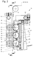
- Fig. 2
- eine Verbindungsstation von Aufreißstreifen und Folienbahn, ebenfalls in Seitenansicht, bei vergrößertem Maßstab,
- Fig. 3
- eine Einzelheit der Vorrichtung gemäß Fig. 2 in nochmals vergrößertem Maßstab, teilweise im Vertikalschnitt,
- Fig. 4
- eine einzelne Druck- bzw. Siegelrolle im Radialschnitt, nochmals vergrößert,
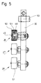
- Fig. 5
- eine Halterung mit Gegendruckrollen in Seitenansicht.
- Das vorliegende Ausführungsbeispiel ist besonders geeignet im Zusammenhang mit der Fertigung von Zigarettenpackungen mit einer Außenumhüllung aus Zellglas oder Kunststoffolie mit einem Aufreißstreifen. Fig. 1 zeigt ein Folienaggregat als Teil einer Verpackungsmaschine.
- Eine Folienbahn 10 wird fortlaufend von einer Bobine 11 abgezogen und über eine Vielzahl von Umlenk- und Steuerwalzen geführt. Ein Aufreißstreifen 12, 13 wird bei kontinuierlichem Transport der Folienbahn 10 an diese angelegt und im Bereich einer Siegelstation 14 ebenfalls bei fortlaufendem Transport mit der Folienbahn 10 durch Aufwendung von Wärme und Druck verbunden. Die Einheit aus Folienbahn 10 und Aufreißstreifen 12, 13 wird der Verpackungsmaschine zugeführt bzw. einem Trennaggregat zum Abtrennen von Zuschnitten für die Außenumhüllung.
- Eine Besonderheit der in Fig. 1 gezeigten Einrichtung besteht darin, daß diese für zweibahnige Betriebsweise ausgelegt ist. Die von der Bobine 11 abgezogene Folienbahn 10 hat doppelte Breite. Im Bereich einer Trennstation 15 wird die Folienbahn 10 in zwei nebeneinanderlaufende Folienbahnen halber Breite durch einen mittleren Längsschnitt aufgeteilt. Die beiden nebeneinanderlaufenden Folienbahnen 10 werden im Bereich einer Spreizstation 16 durch Spreizrollen 17 so umgelenkt, daß die beiden Folienbahnen 10 in einem Abstand voneinander parallel weitertransportiert werden.
- Jeder der Folienbahnen 10 ist ein Aufreißstreifen 12, 13 zugeordnet. Diese werden von gesonderten Bobinen 18, 19 abgezogen. Im Bereich einer Vereinigungswalze 20, die zugleich Umlenkwalze für die beiden Folienbahnen 10 ist, werden die Aufreißstreifen 12 und 13 an die zugeordneten, nebeneinanderlaufenden Folienbahnen 10 angelegt.
- Beide Folienbahnen 10 mit packungsgerecht anliegenden Aufreißstreifen 12, 13 werden sodann der Siegelstation 14 nebeneinanderlaufend zugeführt. Dort ist jeder Folienbahn 10 mit Aufreißstreifen 12, 13 ein Siegelaggregat 21 zugeordnet. Jede der gleichlaufenden, kontinuierlich geförderten Folienbahnen 10 wird durch ein Siegelaggregat 21 mit dem anliegenden Aufreißstreifen 12, 13 verbunden. Im Anschluß an die Siegelstation 14 werden demnach zwei Folienbahnen 10 mit je einem angesiegelten Aufreißstreifen 12, 13 parallel transportiert und der weiteren Verarbeitung zugeführt.
- Die Aufreißstreifen 12, 13 sind so ausgebildet bzw. mit einer Beschichtung versehen, die eine haltbare Verbindung mit der Folienbahn 10 bei Aufbringen von Wärme und Druck gewährleistet. Das Siegelaggregat 21 ist so ausgebildet, daß Wärme und Druck während des kontinuierlichen Transports der Folienbahnen 10 fortlaufend auf diese bzw. auf die Aufreißstreifen 12, 13 aufgebracht werden.
- Das Siegelaggregat 21 wird bei dem vorliegenden Ausführungsbeispiel im Bereich eines aufrechten Strangs 22 der Folienbahnen 10 und Aufreißstreifen 12, 13 wirksam. In Förderrichtung der Folienbahn wirken mehrere in Längsrichtung der Folienbahn 10 aufeinanderfolgende Siegelrollen 23, 24, 25 auf Folienbahn 10 und Aufreißstreifen 12, 13 ein. Im vorliegenden Falle sind drei Siegelrollen 23, 24, 25 an einem gemeinsamen, aufrechten Träger 26 übereinanderliegend positioniert. Die Siegelrollen 23, 24, 25 liegen im Bereich der Aufreißstreifen 12, 13 unter Übertragung von Druck an den Aufreißstreifen 12, 13 und damit indirekt an den Folienbahnen 10 an.
- Auf der zu den Siegelrollen 23..25 gegenüberliegenden Seite der Folienbahn 10 sind Gegendruckorgane positioniert, nämlich (drei) Gegenrollen 27, 28, 29. Auch die Gegenrollen 27..29 sind an einem gemeinsamen Halter 30 gelagert. Die Gegenrollen 27..29 sind jeweils exakt gegenüber den Siegelrollen 23..25 gelagert. Durch diese werden Folienbahn 10 und Aufreißstreifen 12, 13 während der Förderbewegung an den Umfang der Gegenrollen 27..29 angedrückt. Siegelrollen 23..25 und Gegenrollen 27..29 sind entsprechend der Fördergeschwindigkeit der Folienbahn 10 angetrieben, werden durch diese infolge der Förderbewegung gedreht.
- Die Siegelrollen 23..25 sind beheizt, so daß zum Druck auch die Wärme durch die Siegelrollen 23..25 übertragen wird. Bei dem vorliegenden Ausführungsbeispiel ist eine indirekte Beheizung der Siegelrollen 23..25 vorgesehen, und zwar insbesondere über Strahlungswärme.
- Der Träger 26 ist als Gehäuse 31 ausgebildet, welches die Siegelrollen 23..25 nahezu vollständig umgibt, nämlich bis auf kleine Bereiche bzw. Öffnungen 32 für den Durchtritt von Siegelflächen der Siegelrollen 23..25 im Bereich der Folienbahn 10. Das Gehäuse 31 ist unmittelbar beheizt, im vorliegenden Fall durch eine sich in Längsrichtung erstreckende Heizpatrone 33. Diese ist in einer Bohrung 34 positioniert, die sich auf der zur Folienbahn 10 gegenüberliegenden Seite im Gehäuse 31 unmittelbar neben den Umfangsflächen der Siegelrollen 23..25 erstreckt. Das hierdurch beheizte Gehäuse 31 überträgt die Wärme auf die Siegelrollen 23..25. Am oberen Ende ist die Heizpatrone 33 mit einem Anschluß 35 für elektrische Leitungen versehen.
- Das Gehäuse 31 für die Siegelrollen 23..25 ist in besonderer Weise ausgebildet, derart, daß (Strahlungs-)Wärme von dem Gehäuse 31 unmittelbar auf die Folienbahn 10 bzw. die Aufreißstreifen 12, 13 übertragen wird. Das Gehäuse 31 besteht im vorliegenden Fall aus zwei parallelen Längswänden 36, 37, in denen die Siegelrollen 23..25 mit als Schraubenbolzen ausgebildeten Drehachsen 38 gelagert sind. Wie insbesondere in Fig. 3 und 4 gezeigt, ist ein Drehkranz 39 der Siegelrollen 23..25 mit einem Wälzlager 40 drehbar auf der Drehachse 38 gelagert.
- Die beiden Längswände 36, 37 sind durch quergerichtete Verbindungsbolzen 41 miteinander verbunden. Diese erstrecken sich im Bereich von Querwänden 42 des Gehäuses 31. An den Enden, also oben und unten, ist das Gehäuse 31 durch Endwände 43 geschlossen. Die Siegelrollen 23..25 sind demnach jeweils in Kammern 44 gelagert, die lediglich zur Seite, also in Richtung zur Folienbahn 10, offen sind (Öffnungen 32).
- Das so ausgebildete Gehäuse 31 ist außen von Isolierplatten 45 umgeben, die Wärmeverluste nach außen reduzieren. Die Isolierplatten 45 erstrecken sich im Bereich der Längswände 36, 37 und der Endwände 43. Die Verbindungsbolzen 41 erstrecken sich durch die Isolierplatten 45 hindurch, so daß die Einheit aus Gehäuse 31 und Isolierplatten 45 durch die Verbindungsbolzen 41 zusammengehalten wird. Diese dienen zugleich zur Verbindung der beschriebenen Einheit mit dem als einarmiger Hebel ausgebildeten Träger 26. An diesem ist das Gehäuse 31 demnach seitlich angebracht.
- Zwischen den Siegelrollen 23..25 sind auf der der Folienbahn 10 zugekehrten Seite am Gehäuse 31 zusätzliche Organe zur Übertragung von (Strahlungs-)Wärme auf die Aufreißstreifen 12, 13 angeordnet. Es handelt sich dabei um Stege 46, die als verhältnismäßig dünnwandige Organe exakt im Bereich der Aufreißstreifen 12, 13 am Gehäuse angebracht sind, nämlich an den Querwänden 42 und den Endwänden 43. Die Stege 46 sind so ausgebildet, daß sie mit Abstand der Kontur der Siegelrollen 23..25 folgen und mit geringem Abstand von beispielsweise 1/5 bis 1/2 mm Abstand von dem Aufreißstreifen 12, 13 verlaufen. Dadurch wird berührungslos zusätzlich Wärme übertragen.
- In besonderer Weise sind die Siegelrollen 23..25 ausgebildet. Im Bereich der äußeren Siegelfläche ist ein ringsherumlaufender Siegelsteg 47 gebildet. Dieser entspricht etwa der Breite der Aufreißstreifen 12, 13 bzw. ist geringfügig breiter. Durch diesen Siegelsteg 47 erhält der Drehkranz 39 als äußerer Bereich der Siegelrollen 23..25 einen T-förmigen Querschnitt. Dieser Teil der Siegelrollen 23..25 besteht aus einem metallischen Werkstoff mit hoher Wärmeleitfähigkeit.
- Die Gegenrollen 27..29 haben im vorliegenden Falle nur die Aufgabe, den erforderlichen Gegendruck beim Siegeln zu erzeugen. Die Gegenrollen 27..29 sind ebenfalls mit Wälzlagern 48 auf Achszapfen 49 gelagert. Diese sind seitlich mit dem als einarmiger Hebel ausgebildeten Halter 30 befestigt.
- Die Gegenrollen 27..29 haben eine im Verhältnis zu den Siegelrollen 23..25 breitere äußere Anlage- bzw. Mantelfläche. Bei dem gezeigten Ausführungsbeispiel ist der Außenumfang der Gegenrollen 27..29 elastisch ausgebildet. Wie aus Fig. 5 ersichtlich, ist zu diesem Zweck auf den Gegenrollen 27..29 ein Mantel 50 aus elastischem Werkstoff befestigt, insbesondere aus Silikon. Die Folienbahn 10 wird demnach durch die Siegelrollen 23, 24 gegen den elastischen Mantel 50 gedrückt. Dieser hat, wie gezeigt, hier eine ballige äußere Anlagefläche 51.
- Die Siegelrollen 23..25 und/oder die Gegenrollen 27..29 sind verstellbar gelagert. Im vorliegenden Falle sind der Träger 26 einerseits und der Halter 30 andererseits bewegbar angeordnet. Der winkelförmig ausgebildete Träger 26 ist auf einem feststehenden Tragzapfen 52 drehbar gelagert. Bei Betriebsunterbrechung wird das Siegelaggregat 21 bzw. der Träger 26 mit den Siegelrollen 23..25 außer Anlage an den Folienbahnen 10 bewegt, nämlich durch Verschwenken in die in Fig. 2 strichpunktiert gezeichnete Position.
- Auch der Kalter 30 für die Gegenrollen 27..29 ist einseitig auf einem Haltezapfen 53 drehbar gelagert. Durch diese Lagerung kann die Relativstellung des Halters 30 mit den Gegenrollen 27..29 eingestellt werden.
Claims (10)
- Vorrichtung zum Verbinden eines fortlaufend zugeführten Materialstreifens, insbesondere eines Aufreißstreifens (12, 13), mit einer fortlaufend geförderten Materialbahn, insbesondere einer Folienbahn (10), zum Herstellen von Zuschnitten für Packungsumhüllungen mit Aufreißstreifen, wobei der Aufreißstreifen (12, 13) durch beheizte, nach Maßgabe der Förderbewegung der Folienbahn (10) und des Aufreißstreifens (12, 13) drehende Druck- und Siegelorgane an die Materialbahn andrückbar und mit dieser verbindbar ist, dadurch gekennzeichnet, daß die Druck- und Siegelorgane beheizte Siegelrollen (23, 24, 25) sind, die überwiegend oder ausschließlich indirekt beheizt sind, insbesondere durch Strahlungswärme.
- Vorrichtung nach Anspruch 1, dadurch gekennzeichnet, daß die Siegelrollen (23, 24, 25) in einem Gehäuse (31) aus einem Material hoher Wärmeleitfähigkeit gelagert sind, wobei das Gehäuse beheizt ist, vorzugsweise durch wenigstens eine in dem Gehäuse (31) angeordnete Heizpatrone (33).
- Vorrichtung nach Anspruch 1 oder 2, dadurch gekennzeichnet, daß in Förderrichtung der Folienbahn (10) und des Aufreißstreifens (12, 13) mehrere Paare von einander gegenüberliegenden Siegelrollen (23, 24, 25) und Gegenrollen (27, 28, 29) angeordnet sind, insbesondere drei Paare von (annähernd) gleich großen Siegelrollen (23, 24, 25) und Gegenrollen (27, 28, 29).
- Vorrichtung nach Anspruch 1 oder einem der weiteren Ansprüche, gekennzeichnet durch zusätzliche, in geringem Abstand von der Folienbahn (10) bzw. den Aufreißstreifen (12, 13) positionierte Wärmeübertragungsorgane, vorzugsweise dünnwandige, sich in Längsrichtung des Aufreißstreifens (12, 13) erstreckende Stege (46) aus wärmeleitendem Material, wobei die Stege (46) im Bereich zwischen den in Förderrichtung aufeinanderfolgenden Siegelrollen (23, 24, 25) angeordnet und durch das Gehäuse (31) bzw. durch eine in diesen angeordnete Heizpatrone (33) beheizt sind.
- Vorrichtung nach Anspruch 1 oder einem der weiteren Ansprüche, dadurch gekennzeichnet, daß die Siegelrollen (23, 24, 25) ein (T-förmiges) Profil aufweisen mit einem schmalen äußeren, ringsherumlaufenden Siegelsteg (47) zur Anlage an dem Aufreißstreifen (12, 13), wobei insbesondere der Siegelsteg (47) Teil eines äußeren Drehkranzes (39) der Siegelrollen (23, 24, 25) ist und aus wärmeleitendem Material besteht.
- Vorrichtung nach Anspruch 1 oder einem der weiteren Ansprüche, dadurch gekennzeichnet, daß die Gegenrollen (27, 28, 29) ganz oder teilweise, nämlich mindestens im Bereich eines äußeren Mantels (50), aus elastisch zusammendrückbarem Werkstoff bestehen, vorzugsweise aus Silikon.
- Vorrichtung nach Anspruch 6 oder einem der weiteren Ansprüche, dadurch gekennzeichnet, daß die Gegenrollen (27, 28, 29) eine äußere Anlagefläche für die Folienbahn (10) aufweisen, die eine größere Breite hat als Siegelflächen der Siegelrollen (23, 24, 25), insbesondere als der Siegelsteg (47) derselben.
- Vorrichtung nach Anspruch 1 oder einem der weiteren Ansprüche, dadurch gekennzeichnet, daß die Siegelrollen (23..25) bzw. das Gehäuse (31) an einem Träger (26) angebracht ist, der verstellbar gelagert ist, insbesondere als schwenkbarer, einarmiger Hebel.
- Vorrichtung nach Anspruch 1 oder einem der weiteren Ansprüche, dadurch gekennzeichnet, daß die Gegenrollen (27, 28, 29) an einem Halter (30) angebracht sind, der relativ zu den Siegelrollen (23, 24, 25) verstellbar ist.
- Vorrichtung nach Anspruch 1 oder einem der weiteren Ansprüche, dadurch gekennzeichnet, daß die Siegelrollen (23, 24, 25) und Gegenrollen (27, 28, 29) im Bereich eines aufrechten Förderabschnitts, nämlich eines aufrechten Strangs (22) der Folienbahn (10) wirken.
Applications Claiming Priority (2)
| Application Number | Priority Date | Filing Date | Title |
|---|---|---|---|
| DE19619558A DE19619558A1 (de) | 1996-05-14 | 1996-05-14 | Vorrichtung zum Verbinden eines Aufreißstreifens mit einer Folienbahn |
| DE19619558 | 1996-05-14 |
Publications (2)
| Publication Number | Publication Date |
|---|---|
| EP0807513A1 true EP0807513A1 (de) | 1997-11-19 |
| EP0807513B1 EP0807513B1 (de) | 2002-07-24 |
Family
ID=7794370
Family Applications (1)
| Application Number | Title | Priority Date | Filing Date |
|---|---|---|---|
| EP97107430A Expired - Lifetime EP0807513B1 (de) | 1996-05-14 | 1997-05-06 | Vorrichtung zum Verbinden eines Aufreissstreifens mit einer Folienbahn |
Country Status (5)
| Country | Link |
|---|---|
| US (1) | US5858167A (de) |
| EP (1) | EP0807513B1 (de) |
| JP (1) | JP3790012B2 (de) |
| CN (1) | CN1105064C (de) |
| DE (2) | DE19619558A1 (de) |
Cited By (3)
| Publication number | Priority date | Publication date | Assignee | Title |
|---|---|---|---|---|
| WO1998032588A1 (de) * | 1997-01-24 | 1998-07-30 | Tiromat Krämer + Grebe GmbH & Co. KG | Verfahren und vorrichtung zum siegeln von folienbahnen |
| FR2811935A1 (fr) * | 2000-07-18 | 2002-01-25 | Windmoeller & Hoelscher | Dispositif de scellement thermique |
| IT202300013311A1 (it) * | 2023-06-27 | 2024-12-27 | Pfm S P A | Dispositivo di saldatura per macchina confezionatrice e metodo di saldatura |
Families Citing this family (4)
| Publication number | Priority date | Publication date | Assignee | Title |
|---|---|---|---|---|
| EP1209083B1 (de) | 2000-11-24 | 2004-08-18 | Focke & Co. (GmbH & Co.) | Verfahren und Vorrichtung zum Herstellen von Packungen mit Aussenumhüllung sowie Bobineneinheit |
| US6889483B2 (en) | 2002-10-31 | 2005-05-10 | Cryovac, Inc. | Easy-opening feature for flexible packages and process and apparatus for forming same |
| US7591294B2 (en) * | 2007-11-29 | 2009-09-22 | Spirit Aerosystems, Inc. | Material placement method and apparatus |
| CN105000229B (zh) * | 2015-07-08 | 2017-07-04 | 北京洋航科贸有限公司 | 用于将易撕条封焊于包装体上的装置 |
Citations (14)
| Publication number | Priority date | Publication date | Assignee | Title |
|---|---|---|---|---|
| US2451728A (en) * | 1945-04-17 | 1948-10-19 | Breslee Mfg Company | Heat-sealing apparatus |
| DE819497C (de) * | 1941-12-23 | 1951-10-31 | Fischer & Krecke G M B H | Vorrichtung zum Heissverkleben der Laengsnaehte von Zellglasfolien- oder Kunststoff-Folien-Werkstuecken |
| US2660219A (en) * | 1950-03-15 | 1953-11-24 | Interstate Folding Box Co | Heat-sealing machine |
| US2845213A (en) * | 1953-06-10 | 1958-07-29 | Bernard J Tamarin | Package with tear tab opening means |
| GB961805A (en) * | 1963-01-26 | 1964-06-24 | Holstein & Kappert Maschf | An apparatus for heat sealing papers or the like coated with plastics material |
| US3218961A (en) * | 1961-02-10 | 1965-11-23 | Phillips Petroleum Co | Thermoplastic bag sealer |
| DE1511626A1 (de) * | 1965-07-19 | 1969-09-11 | Hauni Werke Koerber & Co Kg | Vorrichtung in Packmaschinen zum Verbinden von Teilen des Einschlages von Zigarettenpackungen oder anderen blockfoermigen Gegenstaenden |
| US3484325A (en) * | 1966-07-13 | 1969-12-16 | John M Pendleton | Apparatus for sealing thermoplastic films |
| DE2407447A1 (de) * | 1974-02-16 | 1975-08-28 | Phoenix Gummiwerke Ag | Vorrichtung zum herstellen von grossflaechigen planen aus gummi- oder kunststoffbahnen |
| US4067761A (en) * | 1976-12-20 | 1978-01-10 | The Kartridg Pak Co. | Plastic web sealing apparatus using hot air heated sealing roller |
| US4717372A (en) * | 1986-12-08 | 1988-01-05 | Mobil Oil Corporation | Apparatus for producing a machine-direction intermittent heat seal |
| DE3821266A1 (de) * | 1987-06-25 | 1989-01-12 | Gd Spa | Vorrichtung fuer die anbringung eines aufreissstreifens |
| US4808150A (en) * | 1987-09-25 | 1989-02-28 | Mobil Oil Corporation | Oven-heated hot wheel sealing apparatus |
| DE9012482U1 (de) * | 1990-08-31 | 1990-11-08 | Rovema - Verpackungsmaschinen GmbH, 6301 Fernwald | Längssiegelvorrichtung, insbesondere für eine Schlauchbeutelmaschine |
Family Cites Families (15)
| Publication number | Priority date | Publication date | Assignee | Title |
|---|---|---|---|---|
| DE7340444U (de) * | 1975-07-31 | Windmoeller & Hoelscher | Vorrichtung zum Aufschweißen von Verstärkungszetteln auf eine Kunststoffolienbahn | |
| DE1157765B (de) * | 1959-09-24 | 1963-11-21 | Darex A G | Siegelrolle mit elektrischen Heizdraehten zum Versiegeln von thermoplastischen Kunststoff-Folien |
| US3059690A (en) * | 1961-07-05 | 1962-10-23 | Ralph A Nyborg | Heat sealing apparatus |
| AT245492B (de) * | 1963-08-17 | 1966-02-25 | Hamac Hansella Ag | Vorrichtung zum Anbringen der Längsschweißnaht oder -nähte an der oder den Hüllstoffbahnen in Schlauchbeutelverpackungsmaschinen |
| US3804697A (en) * | 1969-11-24 | 1974-04-16 | Schjeldahl Co G T | Moveable heat sealing apparatus |
| DE2237877C3 (de) * | 1972-08-02 | 1979-01-11 | Packautomatic Gmbh & Co Kg, 5828 Ennepetal | Vorrichtung zum Verschweißen der seitlich überragenden Enden einer ein Packstück enthaltenden schlauchf örmigen Folienhülle |
| US4270965A (en) * | 1976-10-06 | 1981-06-02 | Torterotot Roland | Production of sterile packages |
| JPS55123411U (de) * | 1979-02-23 | 1980-09-02 | ||
| US4288967A (en) * | 1979-11-30 | 1981-09-15 | Fuji Machinery Co. Ltd. | Center sealing device for a plastic film in a packaging apparatus |
| DE3542256A1 (de) * | 1985-11-29 | 1987-06-04 | Hoechst Ag | Vorrichtung zum kontinuierlichen schweissen bzw. siegeln von naehten von kunststoff-folien |
| US4666550A (en) * | 1986-02-24 | 1987-05-19 | Philip Morris Incorporated | Apparatus for producing a strip of laminated sheet material |
| US4721501A (en) * | 1986-09-08 | 1988-01-26 | Mobil Oil Corporation | Apparatus for producing a machine-direction heat seal |
| JPH02258509A (ja) * | 1989-03-28 | 1990-10-19 | Chuo Housouki Kk | 充填包装機に於る包装袋閉じ合せ縁の余剰部切落装置 |
| DE4215690A1 (de) * | 1992-05-14 | 1993-11-18 | Focke & Co | Vorrichtung zum Verbinden eines Aufreißstreifens mit einer Materialbahn |
| JPH0891330A (ja) * | 1994-09-21 | 1996-04-09 | Shikoku Kakoki Co Ltd | シールテープの張付け装置 |
-
1996
- 1996-05-14 DE DE19619558A patent/DE19619558A1/de not_active Withdrawn
-
1997
- 1997-05-06 EP EP97107430A patent/EP0807513B1/de not_active Expired - Lifetime
- 1997-05-06 DE DE59707766T patent/DE59707766D1/de not_active Expired - Lifetime
- 1997-05-13 US US08/855,541 patent/US5858167A/en not_active Expired - Fee Related
- 1997-05-14 CN CN97111549A patent/CN1105064C/zh not_active Expired - Fee Related
- 1997-05-14 JP JP12441497A patent/JP3790012B2/ja not_active Expired - Fee Related
Patent Citations (14)
| Publication number | Priority date | Publication date | Assignee | Title |
|---|---|---|---|---|
| DE819497C (de) * | 1941-12-23 | 1951-10-31 | Fischer & Krecke G M B H | Vorrichtung zum Heissverkleben der Laengsnaehte von Zellglasfolien- oder Kunststoff-Folien-Werkstuecken |
| US2451728A (en) * | 1945-04-17 | 1948-10-19 | Breslee Mfg Company | Heat-sealing apparatus |
| US2660219A (en) * | 1950-03-15 | 1953-11-24 | Interstate Folding Box Co | Heat-sealing machine |
| US2845213A (en) * | 1953-06-10 | 1958-07-29 | Bernard J Tamarin | Package with tear tab opening means |
| US3218961A (en) * | 1961-02-10 | 1965-11-23 | Phillips Petroleum Co | Thermoplastic bag sealer |
| GB961805A (en) * | 1963-01-26 | 1964-06-24 | Holstein & Kappert Maschf | An apparatus for heat sealing papers or the like coated with plastics material |
| DE1511626A1 (de) * | 1965-07-19 | 1969-09-11 | Hauni Werke Koerber & Co Kg | Vorrichtung in Packmaschinen zum Verbinden von Teilen des Einschlages von Zigarettenpackungen oder anderen blockfoermigen Gegenstaenden |
| US3484325A (en) * | 1966-07-13 | 1969-12-16 | John M Pendleton | Apparatus for sealing thermoplastic films |
| DE2407447A1 (de) * | 1974-02-16 | 1975-08-28 | Phoenix Gummiwerke Ag | Vorrichtung zum herstellen von grossflaechigen planen aus gummi- oder kunststoffbahnen |
| US4067761A (en) * | 1976-12-20 | 1978-01-10 | The Kartridg Pak Co. | Plastic web sealing apparatus using hot air heated sealing roller |
| US4717372A (en) * | 1986-12-08 | 1988-01-05 | Mobil Oil Corporation | Apparatus for producing a machine-direction intermittent heat seal |
| DE3821266A1 (de) * | 1987-06-25 | 1989-01-12 | Gd Spa | Vorrichtung fuer die anbringung eines aufreissstreifens |
| US4808150A (en) * | 1987-09-25 | 1989-02-28 | Mobil Oil Corporation | Oven-heated hot wheel sealing apparatus |
| DE9012482U1 (de) * | 1990-08-31 | 1990-11-08 | Rovema - Verpackungsmaschinen GmbH, 6301 Fernwald | Längssiegelvorrichtung, insbesondere für eine Schlauchbeutelmaschine |
Cited By (4)
| Publication number | Priority date | Publication date | Assignee | Title |
|---|---|---|---|---|
| WO1998032588A1 (de) * | 1997-01-24 | 1998-07-30 | Tiromat Krämer + Grebe GmbH & Co. KG | Verfahren und vorrichtung zum siegeln von folienbahnen |
| FR2811935A1 (fr) * | 2000-07-18 | 2002-01-25 | Windmoeller & Hoelscher | Dispositif de scellement thermique |
| IT202300013311A1 (it) * | 2023-06-27 | 2024-12-27 | Pfm S P A | Dispositivo di saldatura per macchina confezionatrice e metodo di saldatura |
| EP4484135A1 (de) * | 2023-06-27 | 2025-01-01 | P.F.M. S.p.A. | Siegelvorrichtung für verpackungsmaschine |
Also Published As
| Publication number | Publication date |
|---|---|
| CN1169388A (zh) | 1998-01-07 |
| CN1105064C (zh) | 2003-04-09 |
| JP3790012B2 (ja) | 2006-06-28 |
| DE19619558A1 (de) | 1997-11-20 |
| DE59707766D1 (de) | 2002-08-29 |
| US5858167A (en) | 1999-01-12 |
| JPH1086916A (ja) | 1998-04-07 |
| EP0807513B1 (de) | 2002-07-24 |
Similar Documents
| Publication | Publication Date | Title |
|---|---|---|
| DE3905440C2 (de) | ||
| DE3142202C2 (de) | ||
| DE2430990C3 (de) | Vorrichtung zum Beschichten der Außenfläche von Flaschen mit Ausnahme des Flaschenbodens mit einem Schutzüberzug | |
| EP2229324B1 (de) | Verfahren zum etikettieren von behältern sowie etikettierstation | |
| DE3724196A1 (de) | Vorrichtung zum auftragen von loesungsmitteln und dergleichen | |
| EP1751005B1 (de) | Verfahren und vorrichtung zum verpacken von flachen objekten | |
| DE4215690A1 (de) | Vorrichtung zum Verbinden eines Aufreißstreifens mit einer Materialbahn | |
| EP0495957B1 (de) | Verfahren und vorrichtung zum trockenen bedrucken eines werkstücks oder druckguts unter verwendung einer heissprägefolie | |
| DE10124695C2 (de) | Kantenanleimaggregat mit Andruckrolle | |
| EP0807513A1 (de) | Vorrichtung zum Verbinden eines Aufreissstreifens mit einer Folienbahn | |
| DE4017906C2 (de) | ||
| EP3253661B1 (de) | Vorrichtung und verfahren zum herstellen von quaderförmigen packungen für zigaretten | |
| EP0812257B1 (de) | Verfahren und vorrichtung zum beheizen einer bewegten bahn, insbesondere wellpappenbahn | |
| DE1586093A1 (de) | Einrichtung zum Aufbringen von Aufreissstreifen auf ein Einschlagmaterialband | |
| EP0014858B1 (de) | Verfahren und Vorrichtung zum Aufbringen von Aufreissbändchen od.dgl. auf eine Materialbahn | |
| DE965384C (de) | Etikettiermaschine fuer aufrechtstehende Gegenstaende | |
| DE3828929A1 (de) | Vorrichtung zum auftragen von klebstoff auf zu verklebende oberflaechen | |
| DE19821253A1 (de) | Beleimungsstation für eine Etikettiermaschine sowie Etikettiermaschine | |
| EP0226810B1 (de) | Verpackungsmaschine | |
| DE10318959B4 (de) | Vorrichtung zur Perforation einer durchlaufenden Materialbahn | |
| DE3725833A1 (de) | Vorrichtung zum auftragen von klebstoff auf blattfoermiges verpackungsmaterial | |
| DE19914609B4 (de) | Vorrichtung zum Bedrucken von Materialbahnen | |
| EP0406988B1 (de) | Prägekalander | |
| DE20006315U1 (de) | Etikettiervorrichtung | |
| DE102005005215B3 (de) | Verfahren und Vorrichtung zum Fenstereinschweißen in Faltschachtelzuschnitten |
Legal Events
| Date | Code | Title | Description |
|---|---|---|---|
| PUAI | Public reference made under article 153(3) epc to a published international application that has entered the european phase |
Free format text: ORIGINAL CODE: 0009012 |
|
| AK | Designated contracting states |
Kind code of ref document: A1 Designated state(s): CH DE GB IT LI |
|
| 17P | Request for examination filed |
Effective date: 19971227 |
|
| 17Q | First examination report despatched |
Effective date: 19990526 |
|
| GRAG | Despatch of communication of intention to grant |
Free format text: ORIGINAL CODE: EPIDOS AGRA |
|
| GRAG | Despatch of communication of intention to grant |
Free format text: ORIGINAL CODE: EPIDOS AGRA |
|
| GRAH | Despatch of communication of intention to grant a patent |
Free format text: ORIGINAL CODE: EPIDOS IGRA |
|
| GRAH | Despatch of communication of intention to grant a patent |
Free format text: ORIGINAL CODE: EPIDOS IGRA |
|
| GRAA | (expected) grant |
Free format text: ORIGINAL CODE: 0009210 |
|
| AK | Designated contracting states |
Kind code of ref document: B1 Designated state(s): CH DE GB IT LI |
|
| REG | Reference to a national code |
Ref country code: GB Ref legal event code: FG4D Free format text: NOT ENGLISH |
|
| REG | Reference to a national code |
Ref country code: CH Ref legal event code: EP |
|
| GBT | Gb: translation of ep patent filed (gb section 77(6)(a)/1977) |
Effective date: 20020724 |
|
| REG | Reference to a national code |
Ref country code: CH Ref legal event code: NV Representative=s name: DIPL.-ING. ETH H. R. WERFFELI PATENTANWALT |
|
| REF | Corresponds to: |
Ref document number: 59707766 Country of ref document: DE Date of ref document: 20020829 |
|
| PLBE | No opposition filed within time limit |
Free format text: ORIGINAL CODE: 0009261 |
|
| STAA | Information on the status of an ep patent application or granted ep patent |
Free format text: STATUS: NO OPPOSITION FILED WITHIN TIME LIMIT |
|
| 26N | No opposition filed |
Effective date: 20030425 |
|
| PGFP | Annual fee paid to national office [announced via postgrant information from national office to epo] |
Ref country code: CH Payment date: 20060515 Year of fee payment: 10 |
|
| REG | Reference to a national code |
Ref country code: CH Ref legal event code: PL |
|
| PG25 | Lapsed in a contracting state [announced via postgrant information from national office to epo] |
Ref country code: CH Free format text: LAPSE BECAUSE OF NON-PAYMENT OF DUE FEES Effective date: 20070531 Ref country code: LI Free format text: LAPSE BECAUSE OF NON-PAYMENT OF DUE FEES Effective date: 20070531 |
|
| PGFP | Annual fee paid to national office [announced via postgrant information from national office to epo] |
Ref country code: IT Payment date: 20090516 Year of fee payment: 13 |
|
| PGFP | Annual fee paid to national office [announced via postgrant information from national office to epo] |
Ref country code: GB Payment date: 20090506 Year of fee payment: 13 |
|
| GBPC | Gb: european patent ceased through non-payment of renewal fee |
Effective date: 20100506 |
|
| PG25 | Lapsed in a contracting state [announced via postgrant information from national office to epo] |
Ref country code: IT Free format text: LAPSE BECAUSE OF NON-PAYMENT OF DUE FEES Effective date: 20100506 |
|
| PG25 | Lapsed in a contracting state [announced via postgrant information from national office to epo] |
Ref country code: GB Free format text: LAPSE BECAUSE OF NON-PAYMENT OF DUE FEES Effective date: 20100506 |
|
| PGFP | Annual fee paid to national office [announced via postgrant information from national office to epo] |
Ref country code: DE Payment date: 20130527 Year of fee payment: 17 |
|
| REG | Reference to a national code |
Ref country code: DE Ref legal event code: R119 Ref document number: 59707766 Country of ref document: DE |
|
| REG | Reference to a national code |
Ref country code: DE Ref legal event code: R119 Ref document number: 59707766 Country of ref document: DE Effective date: 20141202 |
|
| PG25 | Lapsed in a contracting state [announced via postgrant information from national office to epo] |
Ref country code: DE Free format text: LAPSE BECAUSE OF NON-PAYMENT OF DUE FEES Effective date: 20141202 |