EP0807377A2 - Dispositif pour connecter un outil réglable en hauteur à un véhicule d'une position de travail dans une position de transport - Google Patents
Dispositif pour connecter un outil réglable en hauteur à un véhicule d'une position de travail dans une position de transport Download PDFInfo
- Publication number
- EP0807377A2 EP0807377A2 EP97107538A EP97107538A EP0807377A2 EP 0807377 A2 EP0807377 A2 EP 0807377A2 EP 97107538 A EP97107538 A EP 97107538A EP 97107538 A EP97107538 A EP 97107538A EP 0807377 A2 EP0807377 A2 EP 0807377A2
- Authority
- EP
- European Patent Office
- Prior art keywords
- vehicle
- swivel mechanism
- shaft
- working position
- transport position
- Prior art date
- Legal status (The legal status is an assumption and is not a legal conclusion. Google has not performed a legal analysis and makes no representation as to the accuracy of the status listed.)
- Withdrawn
Links
Images


Classifications
-
- A—HUMAN NECESSITIES
- A01—AGRICULTURE; FORESTRY; ANIMAL HUSBANDRY; HUNTING; TRAPPING; FISHING
- A01D—HARVESTING; MOWING
- A01D75/00—Accessories for harvesters or mowers
- A01D75/30—Arrangements for trailing two or more mowers
Definitions
- the invention relates to a device for connecting a device which is adjustable in height from a working position into a transport position to a vehicle with a cantilever arm connected to the device and with a lifting device.
- This known device (US-A-4 854 112) is found on a large-area rotary mower in the form of a lawn mower with a front and one side provided cutting unit.
- the working widths that can be achieved can be up to five meters, and the device for connecting the device relates to the connection of the cutting units provided on either side of the vehicle.
- These can be folded up into a transport position for transport trips or independently in work, for example if a cutting unit has to avoid an obstacle, such as a tree. When folded up, the cutting units then assume a position in which the operator's view to the side is not or is not significantly impaired.
- each lateral cutting unit is connected to a cantilever arm which can be pivoted on the vehicle side about a horizontal shaft running in the direction of travel.
- the horizontal shaft is provided relatively high on the vehicle, which leads to an impairment of the cutting quality when a cutting unit or the vehicle strikes uneven ground.
- a double-acting cylinder which engages the boom arm to flip up the respective cutting unit, must assume a floating position so that a pivoting of the boom arm around its vehicle-side connection point is possible in the working position when it hits bumps on the ground.
- the extension arm is also provided with a joint and an integrated cam control, which causes each cutting unit to rotate about 90 ° backwards when folded up into the transport position.
- the combination of joint and cam control is of course complex and requires further measures to safely guide the cutting unit in the working position.
- the object to be achieved with the invention is seen in improving the device for connecting a device to a vehicle in such a way that a satisfactory work result is achieved in the working position of the device even when the device and / or vehicle is on Bumps on the floor, but a sufficiently large floor clearance is guaranteed in the transport position.
- the invention provides that the cantilever arm is connected to a first part, that a second part is articulated to the first part via a first swivel mechanism, and that the second part is articulated to the vehicle via a second swivel mechanism arranged higher than the first swivel mechanism , wherein the first part can be moved up and down together with the cantilever arm when the lifting device is not actuated and in the working position of the device by the first swiveling mechanism and, when the lifting device is actuated, for moving the device from the working position into the transport position by the first swiveling mechanism against the second part is and subsequent can be folded up together with the second part around the second pivot mechanism.
- the first swivel mechanism can be arranged relatively low because, according to the invention, it is also swiveled up when it is folded up into the transport position.
- the movements are relatively simple. In the working position, the device can move up and down when it hits uneven floors. The lifting device remains unaffected. If, on the other hand, the lifting device is actuated, the device first tilts about the first pivot mechanism or about the corresponding pivot axis until the tilting movement is stopped by contact with the second part. The device is then pivoted with its arm, the first part, the first pivot mechanism and the second part about the second pivot mechanism or about its corresponding pivot axis, which is relatively high.
- the invention provides, according to a further aspect, that a third swivel mechanism is provided between the vehicle and the second swivel mechanism, said third swivel mechanism running at right angles to the second swivel mechanism, the second part via a connecting link is connected to the vehicle. In this way, a forced rotation of the device still takes place during the swiveling up.
- the device according to the invention can be used particularly well if the device is designed as a cutting unit that can be connected laterally to a vehicle, the first swivel mechanism extending in the direction of travel, being arranged at a height that corresponds to the cutting plane of the cutting unit and parallel or approximately parallel to it second pivot mechanism runs.
- a simple stabilization of the first swivel axis is achieved in that the vehicle is provided with an extension arm which runs transversely to the direction of travel and projects laterally from the vehicle and against which the second part rests in the working position of the device.
- This boom is part of the third swivel mechanism, since the boom has a wave shape and has a sleeve at the end which receives a shaft belonging to the second swivel mechanism.
- the lifting device can be provided with a lever part which is mounted on the shaft of the second swivel mechanism, at its lower end with a hydraulic cylinder and at its upper end via a connecting piece on the first part or is connected to the cantilever arm, the connecting piece having an elongated hole into which a draw bolt engages on the first part or on the cantilever arm.
- the lifting device does not act directly on the device, and the hydraulic system does not need to be designed such that the hydraulic cylinder can assume a floating position if the device is to perform pitching movements when driving over uneven ground. These are made possible by the elongated hole.
- the device can be optionally locked in its upward and backward folded transport positions. This makes it possible to quickly fold up and lower the device again without locking, for example in cases where an obstacle is to be avoided.
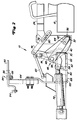
- 1 to 14 relate to the connection devices or to the suspension 10 for the lateral cutting units of a large-area rotary mower.
- 1 shows a self-propelled device 12 which is equipped with a front cutting unit 14 and a left and right wing-like cutting unit 16 and 18.
- Hydraulic motors 20 on the cutting units serve to drive the sickle knives 22 rotating around vertical axes.
- Each cutting unit has several sickle knives, so in the preferred embodiment three sickle knives can be seen on the front cutting unit and two on the two lateral cutting units. In this way, when the lawnmower designed for commercial use is moving forward, it can be mowed with a relatively large cutting width.
- connection mechanism 26 was also designed such that a rearward evasive movement to avoid damage is possible when the cutting unit encounters obstacles. Details of the connection mechanism can be found in the applicant's European patent application of the same day, which claims priority from US application number 648,237 dated May 13, 1966. We expressly refer to this registration.
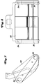
- the pressing part 24 is connected to the device 12 via the suspension 10.
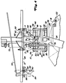
- the inner end of the pressing part 24 is fixedly connected to a vertically downwardly pointing first part 30, which is articulated at its lower end to a pivot mechanism 32, by which it is also carried, for which purpose it is provided with a sleeve 34 which is rotatably received by a first shaft 36.
- the first shaft 36 is in turn received in openings 38 which are provided in a second part 40.
- a rotationally fixed connection is achieved in that a plate 42 is welded to one end of the first shaft 36, which is connected to the second part 40 via a screw 44.
- the second part 40 in turn is articulated on a second pivot mechanism 46, by which it is also carried.
- the second swivel mechanism includes a second one Shaft 48, to the end of which a plate 50 is welded, which is connected to the second part 40 by a screw 52. 5 and 6 that the second shaft 48 is received by openings 54 in the second part 40 and can be rotated in openings 56 of a third part 58.
- the third part in turn is hinged to a third pivot mechanism 60, by which it is also carried.
- the third pivot mechanism 60 includes a third shaft 62 that extends laterally outward from the vehicle frame 64.
- the third shaft is fixed and provided with two bearings 66, which rotatably support a tube 68.
- the tube 68 is fixedly connected to the third part 58 or is part of the same, so that the third part can pivot about the axis of the third shaft 62.
- the pipe 68 is secured on the third shaft 62 via a snap ring 70 at the end of the third shaft 62.
- the cutting unit can be folded up from its working position into a transport position.
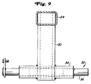
- a lifting device is provided, to which a hydraulically actuatable cylinder 72 belongs.
- This cylinder is connected at one end to the vehicle frame 64 and at the other end to a lifting part 74 which is rotatably mounted on the second shaft 48 between its ends.
- the lifting part is L-shaped or approximately L-shaped, wherein a connecting piece 76 engages in an articulated manner at its upper end.
- the connecting piece 76 is also provided with an elongated hole 78, in which a tension bolt 80 engages, which is firmly connected to the pressing part 24.
- the lifting device also includes a linkage part 82 which engages at one end on the vehicle frame 64 and at the other end on the second part 40 so that the cutting unit can still be pivoted backwards in its folded-up state. This will be explained in more detail later.
- the cutting units can also be locked in their transport position.
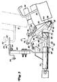
- the locking device 84 provided for this purpose, as can easily be seen from FIGS. 1 to 4, has a bolt 86 pivotally connected to the vehicle frame, which is pressed into its external locking position by a torsion spring 88, in which a hook part 90 of the bolt in the transport position of the cutting unit can detect a boom 92 which is provided on the pressing part 24.
- a control rod 94 extending up to the driver's station can be ascertained in the locking position in which the boom is locked with the bolt.
- the control rod can also be fixed in a second position, in which the bolt assumes a position in which it cannot be locked with the boom when the cutting unit is folded up. This enables the operator to quickly raise and lower the cutting unit again, for example in such cases when an obstacle is to be avoided.
- the cutting units of such a large-area rotary mower are guided on the ground by a plurality of pendulum wheels 96 when mowing.
- the push arm 24 connected to the device 12 pushes the associated lateral cutting unit. If the device 12 and / or the cutting units hit an uneven terrain, the cutting units can face the device Carry out swiveling movements so that the desired excellent lawn cut does not suffer.
- the pressing part 24 can pivot about the axis of the first shaft 36 when driving over uneven terrain. It should be pointed out here that the first shaft 36 is arranged at the same height as the cutting knives 22, so that when the cutting unit is pivoted relative to the device, generally no uncut grass remains.
- the pull bolt 80 is adjusted in the elongated hole 78 provided in the connecting piece 76.
- the elongated hole enables the cutting unit 18 to pivot about 18 ° up and down from its horizontal working position.
- the second part 40 does not normally change its position since, as can be seen from FIG. 2, it rests against the front end of the third shaft 62 with its correspondingly designed rear side.
- the side cutting units can be folded up independently of one another, which is desirable when a side unit has to avoid an obstacle, for example a tree.
- the adjustment in the lockable transport position can be done together.
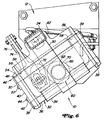
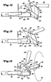
- the corresponding cylinder 72 is first pressurized for folding up.
- the piston rod is extended, and the lever part 74 moves from its position in FIG. 2 counterclockwise about the axis of the second shaft 48.
- the upper end of the lever part pivots to the left with reference to the illustration in FIG. 2, at the same time the connector 76 is taken to the left.
- the third pivot mechanism 60 and the linkage part 82 cooperate in such a way that after the first part 30 bears against the second part 40, the side unit 18 is turned backwards on the third shaft 62.
- the relatively rigid linkage part 82 extends between point A on the vehicle frame 64 and point B on the second part 40.
- the linkage part 82 prevents the second part 40 from shifting along the line C when it is folded up. Rather, it moves backwards on the circular arc D, since the linkage part 82 keeps the distance between the points A and B constant. Due to the rigid connection via the linkage part 82, the second part 40 together with the first part 30 is moved from its position in FIG.
- the processes described for folding up are essentially reversed.
- the corresponding cylinders are retracted for lowering and the cutting units lower due to their own weight.
- the first and second parts 30 and 40 first rotate forward about the axis of the third shaft 62 and at the same time downward about the axis of the second shaft 48.
- the rotational movement about the axis of the second shaft 48 has ended and the downward rotation about the axis of the first shaft 36 can begin.
Landscapes
- Life Sciences & Earth Sciences (AREA)
- Environmental Sciences (AREA)
- Harvester Elements (AREA)
Applications Claiming Priority (2)
| Application Number | Priority Date | Filing Date | Title |
|---|---|---|---|
| US645367 | 1996-05-13 | ||
| US08/645,367 US5715667A (en) | 1996-05-13 | 1996-05-13 | Wing deck mounting and lift mechanism |
Publications (2)
| Publication Number | Publication Date |
|---|---|
| EP0807377A2 true EP0807377A2 (fr) | 1997-11-19 |
| EP0807377A3 EP0807377A3 (fr) | 1999-06-16 |
Family
ID=24588725
Family Applications (1)
| Application Number | Title | Priority Date | Filing Date |
|---|---|---|---|
| EP97107538A Withdrawn EP0807377A3 (fr) | 1996-05-13 | 1997-05-07 | Dispositif pour connecter un outil réglable en hauteur à un véhicule d'une position de travail dans une position de transport |
Country Status (3)
| Country | Link |
|---|---|
| US (1) | US5715667A (fr) |
| EP (1) | EP0807377A3 (fr) |
| CA (1) | CA2197795A1 (fr) |
Cited By (2)
| Publication number | Priority date | Publication date | Assignee | Title |
|---|---|---|---|---|
| DE19951080A1 (de) * | 1999-10-23 | 2001-04-26 | Deere & Co | Selbstfahrendes landwirtschaftliches Fahrzeug |
| DE102011080385B3 (de) * | 2011-06-10 | 2012-12-06 | Wiedenmann Gmbh | Mähdeck |
Families Citing this family (21)
| Publication number | Priority date | Publication date | Assignee | Title |
|---|---|---|---|---|
| US6079193A (en) * | 1999-01-29 | 2000-06-27 | Deere & Company | Implement suspension with lost motion coupling |
| US6223510B1 (en) * | 1999-06-08 | 2001-05-01 | Gary L. Gillins | Mower deck with object tracing capability |
| US6301863B1 (en) * | 1999-11-22 | 2001-10-16 | Eugene J Liebrecht | Multi-blade circumrotational trimmer |
| US6481194B1 (en) | 2000-05-24 | 2002-11-19 | Deere & Company | Cutting implement height adjustment mechanism having grouped height selections |
| IT251364Y1 (it) * | 2000-11-13 | 2003-11-19 | Rotomec Spa | Falciaerba con sistema migliorato dei piatti falcianti |
| US6647705B2 (en) * | 2001-07-09 | 2003-11-18 | Deere & Company | Flex wing rotary cutter having cushioning strut mounted across wing hinge |
| FR2837347B1 (fr) | 2002-03-21 | 2004-07-30 | Kuhn Sa | Faucheuse agricole comportant un vehicule porteur et plusieurs unites de travail |
| DE10228880B4 (de) * | 2002-06-27 | 2005-09-08 | Jakob Voets Ing. Grad. Gmbh & Co. Kg Rheinische Landschaftspflege | Mähgerät zur Rasen- und Landschaftswiesenpflege mit einer Vorrichtung zur Aufnahme und Zerkleinerung von Mähgut |
| US6901728B2 (en) | 2002-12-10 | 2005-06-07 | Gary L. Kelderman | Expanding and contracting implements |
| ITRE20030108A1 (it) * | 2003-11-12 | 2005-05-13 | Gianni Ferrari S R L | Rasaerba con piatti di taglio laterali. |
| US7313902B1 (en) | 2004-09-14 | 2008-01-01 | Commercial Turf Products, Ltd. | Folding deck mechanism |
| FR2881609B1 (fr) * | 2005-02-09 | 2007-03-09 | Kuhn Sa Sa | Engin agricole pour la coupe de produits comportant un vehicule porteur et des unites de travail |
| US7478519B2 (en) * | 2005-10-13 | 2009-01-20 | Deere & Company | Mounting rotary cutting deck to lift arm |
| US7401456B2 (en) * | 2005-11-08 | 2008-07-22 | Deere & Company | Horizontally retractable mower deck |
| CA2585274C (fr) * | 2007-04-10 | 2011-07-19 | Stanley J. Boyko | Elevateur a aile autobloquant decentre de faucheuse rotative |
| US20100192533A1 (en) * | 2009-01-30 | 2010-08-05 | John Coleman | Turf treatment apparatus with floating head suspended from a frame |
| US20100313536A1 (en) * | 2009-06-11 | 2010-12-16 | Ron Berko | Double cut lawnmower attachment |
| US20140223878A1 (en) * | 2013-02-08 | 2014-08-14 | Robert Sassone | Lawn Mower Assemblies |
| JP5940623B2 (ja) * | 2014-10-21 | 2016-06-29 | 株式会社Ihiシバウラ | 芝刈り車両 |
| US10980176B1 (en) * | 2018-12-06 | 2021-04-20 | Gerald H. Schreurs | Minimal radius system for cutting vegetation |
| US11147209B1 (en) * | 2021-04-01 | 2021-10-19 | Ataco Steel Products Corp. | Riding lawn mower |
Family Cites Families (13)
| Publication number | Priority date | Publication date | Assignee | Title |
|---|---|---|---|---|
| US3500619A (en) * | 1967-04-24 | 1970-03-17 | Fmc Corp | Sectionalized mower |
| US3736735A (en) * | 1971-07-14 | 1973-06-05 | Deere & Co | Mechanism for retaining the wing section of an implement in its raised position |
| US4573306A (en) * | 1980-07-01 | 1986-03-04 | E. E. White | Beltless swingarm mower |
| US4497160A (en) * | 1983-04-29 | 1985-02-05 | Excel Industries, Inc. | Mower with lateral extension wings |
| US4869057A (en) * | 1987-05-26 | 1989-09-26 | Mtd Products Inc. | Mower deck height and angle control |
| US4742671A (en) * | 1987-08-17 | 1988-05-10 | New Holland Inc. | Crop harvesting machine base unit lift mechanism providing auxiliary height boost to crop gathering attachment |
| US4854112A (en) * | 1987-09-04 | 1989-08-08 | The Toro Company | Turf maintenance apparatus |
| US4864805A (en) * | 1987-09-04 | 1989-09-12 | The Toro Company | System for supporting a working unit |
| FR2635433B1 (fr) * | 1988-08-18 | 1991-02-01 | Kuhn Sa | Faucheuse a chassis perfectionne |
| US5069022A (en) * | 1990-09-28 | 1991-12-03 | Befco, Inc. | Gang mower apparatus |
| US5241808A (en) * | 1992-04-10 | 1993-09-07 | Schulte Industries Ltd. | Wing lifting mechanism for rotary mowers |
| US5381647A (en) * | 1993-10-28 | 1995-01-17 | Trail-Buster Dozer, Inc. | ATV mower articulating hitch |
| US5463853A (en) * | 1994-08-22 | 1995-11-07 | Santoli; Domenico | Lawnmower with adjustable side cutters |
-
1996
- 1996-05-13 US US08/645,367 patent/US5715667A/en not_active Expired - Fee Related
-
1997
- 1997-02-17 CA CA002197795A patent/CA2197795A1/fr not_active Abandoned
- 1997-05-07 EP EP97107538A patent/EP0807377A3/fr not_active Withdrawn
Cited By (2)
| Publication number | Priority date | Publication date | Assignee | Title |
|---|---|---|---|---|
| DE19951080A1 (de) * | 1999-10-23 | 2001-04-26 | Deere & Co | Selbstfahrendes landwirtschaftliches Fahrzeug |
| DE102011080385B3 (de) * | 2011-06-10 | 2012-12-06 | Wiedenmann Gmbh | Mähdeck |
Also Published As
| Publication number | Publication date |
|---|---|
| US5715667A (en) | 1998-02-10 |
| CA2197795A1 (fr) | 1997-11-14 |
| EP0807377A3 (fr) | 1999-06-16 |
Similar Documents
| Publication | Publication Date | Title |
|---|---|---|
| EP0475021B1 (fr) | Tondeuse, en particulier tondeuse frontale | |
| EP0807377A2 (fr) | Dispositif pour connecter un outil réglable en hauteur à un véhicule d'une position de travail dans une position de transport | |
| DE2053073C3 (de) | Mähmaschine | |
| EP1106051A1 (fr) | Faucheuse | |
| DE3326297A1 (de) | Fahrzeug mit schwingungsbegrenzung | |
| DE69300977T2 (de) | Heumaschine mit dynamischer Entlastungsvorrichtung | |
| DE60205226T2 (de) | Buschmäherfahrzeug | |
| DE10321683B4 (de) | Pfosten-Freimäher und Verfahren zum Einsatz des Freimähers | |
| EP1266551B1 (fr) | Appareil de travail pour le montage sur véhicule | |
| DE60112351T2 (de) | Heuwerbungsmaschine | |
| EP0807376A2 (fr) | Protection de collision pour une faucheuse connectable à un véhicule | |
| DE1482095C3 (de) | Mähmaschine | |
| DE4108449C2 (fr) | ||
| DE4314250C1 (de) | Tragrahmen für ein Rotormähwerk großer Arbeitsbreite | |
| DE102012108904A1 (de) | Geräteanbauvorrichtung eines Arbeitsfahrzeugs | |
| DE4142496C2 (de) | Heuwerbungsmaschine | |
| EP0289864A1 (fr) | Machine de fenaison | |
| DE3835367C2 (de) | Vorrichtung für Mähwerke zur Bodenanpassung der Schneidwerke | |
| EP0469351A1 (fr) | Dispositif d'attelage d'une tondeuse frontale à un véhicule motorisé | |
| DE2529928C2 (de) | Anbauvorrichtung für eine landwirtschaftliche Maschine | |
| DE3106929A1 (de) | Anbau-frontmaeher mit hin- und hergehenden maehmessern | |
| DE3713474A1 (de) | Heuwerbungsmaschine | |
| DE4103011C2 (de) | Mäh- oder Heumaschine | |
| DE2230245A1 (de) | Maehmaschine | |
| DE9414597U1 (de) | Gezogene Mähmaschine |
Legal Events
| Date | Code | Title | Description |
|---|---|---|---|
| PUAI | Public reference made under article 153(3) epc to a published international application that has entered the european phase |
Free format text: ORIGINAL CODE: 0009012 |
|
| AK | Designated contracting states |
Kind code of ref document: A2 Designated state(s): DE FR GB IE IT |
|
| PUAL | Search report despatched |
Free format text: ORIGINAL CODE: 0009013 |
|
| AK | Designated contracting states |
Kind code of ref document: A3 Designated state(s): DE FR GB IE IT |
|
| RIC1 | Information provided on ipc code assigned before grant |
Free format text: 6A 01D 75/30 A, 6A 01B 73/04 B |
|
| STAA | Information on the status of an ep patent application or granted ep patent |
Free format text: STATUS: THE APPLICATION IS DEEMED TO BE WITHDRAWN |
|
| 18D | Application deemed to be withdrawn |
Effective date: 19991201 |