EP0807377A2 - Device for connecting a height adjustable implement to a vehicle from a working in a transport position - Google Patents
Device for connecting a height adjustable implement to a vehicle from a working in a transport position Download PDFInfo
- Publication number
- EP0807377A2 EP0807377A2 EP97107538A EP97107538A EP0807377A2 EP 0807377 A2 EP0807377 A2 EP 0807377A2 EP 97107538 A EP97107538 A EP 97107538A EP 97107538 A EP97107538 A EP 97107538A EP 0807377 A2 EP0807377 A2 EP 0807377A2
- Authority
- EP
- European Patent Office
- Prior art keywords
- vehicle
- swivel mechanism
- shaft
- working position
- transport position
- Prior art date
- Legal status (The legal status is an assumption and is not a legal conclusion. Google has not performed a legal analysis and makes no representation as to the accuracy of the status listed.)
- Withdrawn
Links
Images


Classifications
-
- A—HUMAN NECESSITIES
- A01—AGRICULTURE; FORESTRY; ANIMAL HUSBANDRY; HUNTING; TRAPPING; FISHING
- A01D—HARVESTING; MOWING
- A01D75/00—Accessories for harvesters or mowers
- A01D75/30—Arrangements for trailing two or more mowers
Definitions
- the invention relates to a device for connecting a device which is adjustable in height from a working position into a transport position to a vehicle with a cantilever arm connected to the device and with a lifting device.
- This known device (US-A-4 854 112) is found on a large-area rotary mower in the form of a lawn mower with a front and one side provided cutting unit.
- the working widths that can be achieved can be up to five meters, and the device for connecting the device relates to the connection of the cutting units provided on either side of the vehicle.
- These can be folded up into a transport position for transport trips or independently in work, for example if a cutting unit has to avoid an obstacle, such as a tree. When folded up, the cutting units then assume a position in which the operator's view to the side is not or is not significantly impaired.
- each lateral cutting unit is connected to a cantilever arm which can be pivoted on the vehicle side about a horizontal shaft running in the direction of travel.
- the horizontal shaft is provided relatively high on the vehicle, which leads to an impairment of the cutting quality when a cutting unit or the vehicle strikes uneven ground.
- a double-acting cylinder which engages the boom arm to flip up the respective cutting unit, must assume a floating position so that a pivoting of the boom arm around its vehicle-side connection point is possible in the working position when it hits bumps on the ground.
- the extension arm is also provided with a joint and an integrated cam control, which causes each cutting unit to rotate about 90 ° backwards when folded up into the transport position.
- the combination of joint and cam control is of course complex and requires further measures to safely guide the cutting unit in the working position.
- the object to be achieved with the invention is seen in improving the device for connecting a device to a vehicle in such a way that a satisfactory work result is achieved in the working position of the device even when the device and / or vehicle is on Bumps on the floor, but a sufficiently large floor clearance is guaranteed in the transport position.
- the invention provides that the cantilever arm is connected to a first part, that a second part is articulated to the first part via a first swivel mechanism, and that the second part is articulated to the vehicle via a second swivel mechanism arranged higher than the first swivel mechanism , wherein the first part can be moved up and down together with the cantilever arm when the lifting device is not actuated and in the working position of the device by the first swiveling mechanism and, when the lifting device is actuated, for moving the device from the working position into the transport position by the first swiveling mechanism against the second part is and subsequent can be folded up together with the second part around the second pivot mechanism.
- the first swivel mechanism can be arranged relatively low because, according to the invention, it is also swiveled up when it is folded up into the transport position.
- the movements are relatively simple. In the working position, the device can move up and down when it hits uneven floors. The lifting device remains unaffected. If, on the other hand, the lifting device is actuated, the device first tilts about the first pivot mechanism or about the corresponding pivot axis until the tilting movement is stopped by contact with the second part. The device is then pivoted with its arm, the first part, the first pivot mechanism and the second part about the second pivot mechanism or about its corresponding pivot axis, which is relatively high.
- the invention provides, according to a further aspect, that a third swivel mechanism is provided between the vehicle and the second swivel mechanism, said third swivel mechanism running at right angles to the second swivel mechanism, the second part via a connecting link is connected to the vehicle. In this way, a forced rotation of the device still takes place during the swiveling up.
- the device according to the invention can be used particularly well if the device is designed as a cutting unit that can be connected laterally to a vehicle, the first swivel mechanism extending in the direction of travel, being arranged at a height that corresponds to the cutting plane of the cutting unit and parallel or approximately parallel to it second pivot mechanism runs.
- a simple stabilization of the first swivel axis is achieved in that the vehicle is provided with an extension arm which runs transversely to the direction of travel and projects laterally from the vehicle and against which the second part rests in the working position of the device.
- This boom is part of the third swivel mechanism, since the boom has a wave shape and has a sleeve at the end which receives a shaft belonging to the second swivel mechanism.
- the lifting device can be provided with a lever part which is mounted on the shaft of the second swivel mechanism, at its lower end with a hydraulic cylinder and at its upper end via a connecting piece on the first part or is connected to the cantilever arm, the connecting piece having an elongated hole into which a draw bolt engages on the first part or on the cantilever arm.
- the lifting device does not act directly on the device, and the hydraulic system does not need to be designed such that the hydraulic cylinder can assume a floating position if the device is to perform pitching movements when driving over uneven ground. These are made possible by the elongated hole.
- the device can be optionally locked in its upward and backward folded transport positions. This makes it possible to quickly fold up and lower the device again without locking, for example in cases where an obstacle is to be avoided.
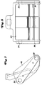
- 1 to 14 relate to the connection devices or to the suspension 10 for the lateral cutting units of a large-area rotary mower.
- 1 shows a self-propelled device 12 which is equipped with a front cutting unit 14 and a left and right wing-like cutting unit 16 and 18.
- Hydraulic motors 20 on the cutting units serve to drive the sickle knives 22 rotating around vertical axes.
- Each cutting unit has several sickle knives, so in the preferred embodiment three sickle knives can be seen on the front cutting unit and two on the two lateral cutting units. In this way, when the lawnmower designed for commercial use is moving forward, it can be mowed with a relatively large cutting width.
- connection mechanism 26 was also designed such that a rearward evasive movement to avoid damage is possible when the cutting unit encounters obstacles. Details of the connection mechanism can be found in the applicant's European patent application of the same day, which claims priority from US application number 648,237 dated May 13, 1966. We expressly refer to this registration.
- the pressing part 24 is connected to the device 12 via the suspension 10.
- the inner end of the pressing part 24 is fixedly connected to a vertically downwardly pointing first part 30, which is articulated at its lower end to a pivot mechanism 32, by which it is also carried, for which purpose it is provided with a sleeve 34 which is rotatably received by a first shaft 36.
- the first shaft 36 is in turn received in openings 38 which are provided in a second part 40.
- a rotationally fixed connection is achieved in that a plate 42 is welded to one end of the first shaft 36, which is connected to the second part 40 via a screw 44.
- the second part 40 in turn is articulated on a second pivot mechanism 46, by which it is also carried.
- the second swivel mechanism includes a second one Shaft 48, to the end of which a plate 50 is welded, which is connected to the second part 40 by a screw 52. 5 and 6 that the second shaft 48 is received by openings 54 in the second part 40 and can be rotated in openings 56 of a third part 58.
- the third part in turn is hinged to a third pivot mechanism 60, by which it is also carried.
- the third pivot mechanism 60 includes a third shaft 62 that extends laterally outward from the vehicle frame 64.
- the third shaft is fixed and provided with two bearings 66, which rotatably support a tube 68.
- the tube 68 is fixedly connected to the third part 58 or is part of the same, so that the third part can pivot about the axis of the third shaft 62.
- the pipe 68 is secured on the third shaft 62 via a snap ring 70 at the end of the third shaft 62.
- the cutting unit can be folded up from its working position into a transport position.
- a lifting device is provided, to which a hydraulically actuatable cylinder 72 belongs.
- This cylinder is connected at one end to the vehicle frame 64 and at the other end to a lifting part 74 which is rotatably mounted on the second shaft 48 between its ends.
- the lifting part is L-shaped or approximately L-shaped, wherein a connecting piece 76 engages in an articulated manner at its upper end.
- the connecting piece 76 is also provided with an elongated hole 78, in which a tension bolt 80 engages, which is firmly connected to the pressing part 24.
- the lifting device also includes a linkage part 82 which engages at one end on the vehicle frame 64 and at the other end on the second part 40 so that the cutting unit can still be pivoted backwards in its folded-up state. This will be explained in more detail later.
- the cutting units can also be locked in their transport position.
- the locking device 84 provided for this purpose, as can easily be seen from FIGS. 1 to 4, has a bolt 86 pivotally connected to the vehicle frame, which is pressed into its external locking position by a torsion spring 88, in which a hook part 90 of the bolt in the transport position of the cutting unit can detect a boom 92 which is provided on the pressing part 24.
- a control rod 94 extending up to the driver's station can be ascertained in the locking position in which the boom is locked with the bolt.
- the control rod can also be fixed in a second position, in which the bolt assumes a position in which it cannot be locked with the boom when the cutting unit is folded up. This enables the operator to quickly raise and lower the cutting unit again, for example in such cases when an obstacle is to be avoided.
- the cutting units of such a large-area rotary mower are guided on the ground by a plurality of pendulum wheels 96 when mowing.
- the push arm 24 connected to the device 12 pushes the associated lateral cutting unit. If the device 12 and / or the cutting units hit an uneven terrain, the cutting units can face the device Carry out swiveling movements so that the desired excellent lawn cut does not suffer.
- the pressing part 24 can pivot about the axis of the first shaft 36 when driving over uneven terrain. It should be pointed out here that the first shaft 36 is arranged at the same height as the cutting knives 22, so that when the cutting unit is pivoted relative to the device, generally no uncut grass remains.
- the pull bolt 80 is adjusted in the elongated hole 78 provided in the connecting piece 76.
- the elongated hole enables the cutting unit 18 to pivot about 18 ° up and down from its horizontal working position.
- the second part 40 does not normally change its position since, as can be seen from FIG. 2, it rests against the front end of the third shaft 62 with its correspondingly designed rear side.
- the side cutting units can be folded up independently of one another, which is desirable when a side unit has to avoid an obstacle, for example a tree.
- the adjustment in the lockable transport position can be done together.
- the corresponding cylinder 72 is first pressurized for folding up.
- the piston rod is extended, and the lever part 74 moves from its position in FIG. 2 counterclockwise about the axis of the second shaft 48.
- the upper end of the lever part pivots to the left with reference to the illustration in FIG. 2, at the same time the connector 76 is taken to the left.
- the third pivot mechanism 60 and the linkage part 82 cooperate in such a way that after the first part 30 bears against the second part 40, the side unit 18 is turned backwards on the third shaft 62.
- the relatively rigid linkage part 82 extends between point A on the vehicle frame 64 and point B on the second part 40.
- the linkage part 82 prevents the second part 40 from shifting along the line C when it is folded up. Rather, it moves backwards on the circular arc D, since the linkage part 82 keeps the distance between the points A and B constant. Due to the rigid connection via the linkage part 82, the second part 40 together with the first part 30 is moved from its position in FIG.
- the processes described for folding up are essentially reversed.
- the corresponding cylinders are retracted for lowering and the cutting units lower due to their own weight.
- the first and second parts 30 and 40 first rotate forward about the axis of the third shaft 62 and at the same time downward about the axis of the second shaft 48.
- the rotational movement about the axis of the second shaft 48 has ended and the downward rotation about the axis of the first shaft 36 can begin.
Landscapes
- Life Sciences & Earth Sciences (AREA)
- Environmental Sciences (AREA)
- Harvester Elements (AREA)
Abstract
Bei einer Vorrichtung zum Anschließen eines aus einer Arbeitsstellung in eine Transportstellung höhenverstellbaren und als Mähwerk ausgebildeten Gerätes an ein Fahrzeug mit einem an das Gerät angeschlossenen Auslegerarm (24) und mit einer Hubvorrichtung ist der Auslegerarm (24) mit einem ersten Teil (30) verbunden und ein zweiter Teil (40) ist über einen ersten Schwenkmechanismus (32) an dem ersten Teil (30) angelenkt und der zweite Teil (40) ist über einen zweiten und höher als der erste Schwenkmechanismus (32) angeordneten Schwenkmechanismus (46) an dem Fahrzeug angelenkt, wobei der erste Teil (30) zusammen mit dem Auslegerarm (24) bei unbetätigter Hubvorrichtung und in der Arbeitsstellung des Gerätes um den ersten Schwenkmechanismus (32) aufund abbewegbar ist und bei betätigter Hubvorrichtung zum Verstellen des Gerätes aus der Arbeitsstellung in die Transportstellung um den ersten Schwenkmechanismus (32) gegen den zweiten Teil (40) schwenkbar ist und nachfolgend zusammen mit dem zweiten Teil (40) um den zweiten Schwenkmechanismus (46) hochklappbar ist.
Description
Die Erfindung bezieht sich auf eine Vorrichtung zum Anschließen eines aus einer Arbeitsstellung in eine Transportstellung höhenverstellbaren Gerätes an ein Fahrzeug mit einem an das Gerät angeschlossenen Auslegerarm und mit einer Hubvorrichtung.The invention relates to a device for connecting a device which is adjustable in height from a working position into a transport position to a vehicle with a cantilever arm connected to the device and with a lifting device.
Diese bekannte Vorrichtung (US-A-4 854 112) findet sich an einem Großflächen-Sichelmäher in Form eines Sitzrasenmähers mit einer vorderen und je einer seitlich vorgesehenen Schneideinheit. Die erzielbaren Arbeitsbreiten können bis zu fünf Meter betragen, und die Vorrichtung zum Anschließen des Gerätes bezieht sich auf den Anschluss der jeweils seitlich neben dem Fahrzeug vorgesehenen Schneideinheiten. Diese können für Transportfahrten gemeinsam in eine Transportstellung hochgeklappt werden oder im Arbeitseinsatz unabhängig voneinander, wenn zum Beispiel eine Schneideinheit einem Hindernis, wie einem Baum, ausweichen muss. Im hochgeklappten Zustand nehmen die Schneideinheiten dann eine Position ein, in der die Sicht der Bedienungsperson zur Seite nicht oder nicht wesentlich beeinträchtigt ist. Im einzelnen ist jede seitliche Schneideinheit an einem Auslegerarm angeschlossen, der fahrzeugseitig um eine in Fahrtrichtung verlaufende horizontale Welle verschwenkbar ist. Damit im hochgeklappten Zustand ein ausreichend großer Bodenabstand entsteht, der bei einem Überfahren von Bordsteinen usw. erforderlich ist, die horizontale Welle relativ hoch am Fahrzeug vorgesehen, was bei einem Auftreffen einer Schneideinheit oder des Fahrzeuges auf Bodenunebenheiten zu einer Beeiträchtigung der Schnittqualität führt. Hinzu kommt, dass bei dieser bekannten Vorrichtung ein doppelseitig beaufschlagbarer Zylinder, der zum Hochklappen der jeweiligen Schneideinheit an dem Auslegerarm angreift, eine Schwimmstellung einnehmen muss, damit ein Verschwenken des Auslegerarms um seine fahrzeugseitige Anschlussstelle bei einem Auftreffen auf Bodenunebenheiten in der Arbeitsstellung überhaupt möglich ist. Damit die Sicht der Bedienungsperson in der Transportstellung nicht übermäßig behindert wird, ist der Auslegerarm noch mit einem Gelenk und einer integrierten Nockensteuerung versehen, wodurch bewirkt wird, dass sich jede Schneideinheit beim Hochklappen in die Transportstellung um etwa 90° nach rückwärts dreht. Die Kombination Gelenk und Nockensteuerung ist natürlich aufwendig und bedingt weitere Maßnahmen, um die Schneideinheit in der Arbeitstellung sicher zu führen.This known device (US-A-4 854 112) is found on a large-area rotary mower in the form of a lawn mower with a front and one side provided cutting unit. The working widths that can be achieved can be up to five meters, and the device for connecting the device relates to the connection of the cutting units provided on either side of the vehicle. These can be folded up into a transport position for transport trips or independently in work, for example if a cutting unit has to avoid an obstacle, such as a tree. When folded up, the cutting units then assume a position in which the operator's view to the side is not or is not significantly impaired. In particular, each lateral cutting unit is connected to a cantilever arm which can be pivoted on the vehicle side about a horizontal shaft running in the direction of travel. So that when the vehicle is folded up, there is a sufficiently large ground clearance that is required when driving over curbs, etc., the horizontal shaft is provided relatively high on the vehicle, which leads to an impairment of the cutting quality when a cutting unit or the vehicle strikes uneven ground. In addition, in this known device, a double-acting cylinder, which engages the boom arm to flip up the respective cutting unit, must assume a floating position so that a pivoting of the boom arm around its vehicle-side connection point is possible in the working position when it hits bumps on the ground. To ensure that the operator's view in the transport position is not obstructed excessively, the extension arm is also provided with a joint and an integrated cam control, which causes each cutting unit to rotate about 90 ° backwards when folded up into the transport position. The combination of joint and cam control is of course complex and requires further measures to safely guide the cutting unit in the working position.
Die mit der Erfindung zu lösende Aufgabe wird nach einem ersten Aspekt darin gesehen, die Vorrichtung zum Anschließen eines Gerätes an ein Fahrzeug dahin gehend zu verbessern, dass in der Arbeitsstellung des Gerätes auch dann ein befriedigendes Arbeitsergebnis erzielt wird, wenn Gerärt und / oder Fahrzeug auf Bodenunebenheiten stoßen, wobei jedoch in der Transportstellung ein ausreichend großer Bodenabstand gewährleistet ist. Hierzu sieht Erfindung vor, dass der Auslegerarm mit einem ersten Teil verbunden ist, dass ein zweiter Teil über einen ersten Schwenkmechanismus an dem ersten Teil angelenkt ist und dass der zweite Teil über einen zweiten und höher als der erste Schwenkmechanismus angeordneten Schwenkmechanismus an das Fahrzeug angelenkt ist, wobei der erste Teil zusammen mit dem Auslegerarm bei unbetätigter Hubvorrichtung und in der Arbeitsstellung des Gerätes um den ersten Schwenkmechanismus auf- und abbewegbar ist und bei betätigter Hubvorrichtung zum Verstellen des Gerätes aus der Arbeitsstellung in die Transportstellung um den ersten Schwenkmechanismus gegen den zweiten Teil schwenkbar ist und nachfolgend zusammen mit dem zweiten Teil um den zweiten Schwenkmechanismus hochklappbar ist. Auf diese Weise kann der erste Schwenkmechanismus relativ niedrig angeordnet werden, weil er nach der Erfindung bei einem Hochklappen in die Transportstellung mithochgeschwenkt wird. Die Bewegungsabläufe sind dabei relativ einfach. In der Arbeitsstellung kann das Gerät bei einem Auftreffen auf Bodenunebenheiten Auf- und Abbewegungen ausführen. Die Hubvorrichtung bleibt davon unbeeinflusst. Wird dagegen die Hubeinrichtung betätigt, so kippt zunächst das Gerät um den ersten Schwenkmechanismus bzw. um die entsprechende Schwenkachse bis die Kippbewegung durch Anlage an den zweiten Teil gestoppt wird. Danach wird das Gerät mit seinem Arm, dem ersten Teil, dem ersten Schwenkmechanismus und dem zweiten Teil um den zweiten Schwenkmechanismus bzw. um dessen entsprechende Schwenkachse, die relativ hoch liegt, verschwenkt.According to a first aspect, the object to be achieved with the invention is seen in improving the device for connecting a device to a vehicle in such a way that a satisfactory work result is achieved in the working position of the device even when the device and / or vehicle is on Bumps on the floor, but a sufficiently large floor clearance is guaranteed in the transport position. For this purpose, the invention provides that the cantilever arm is connected to a first part, that a second part is articulated to the first part via a first swivel mechanism, and that the second part is articulated to the vehicle via a second swivel mechanism arranged higher than the first swivel mechanism , wherein the first part can be moved up and down together with the cantilever arm when the lifting device is not actuated and in the working position of the device by the first swiveling mechanism and, when the lifting device is actuated, for moving the device from the working position into the transport position by the first swiveling mechanism against the second part is and subsequent can be folded up together with the second part around the second pivot mechanism. In this way, the first swivel mechanism can be arranged relatively low because, according to the invention, it is also swiveled up when it is folded up into the transport position. The movements are relatively simple. In the working position, the device can move up and down when it hits uneven floors. The lifting device remains unaffected. If, on the other hand, the lifting device is actuated, the device first tilts about the first pivot mechanism or about the corresponding pivot axis until the tilting movement is stopped by contact with the second part. The device is then pivoted with its arm, the first part, the first pivot mechanism and the second part about the second pivot mechanism or about its corresponding pivot axis, which is relatively high.
Damit in der Transportstellung die Sicht einer Bedienungsperson nicht beeinträchtigt ist, sieht die Erfindung nach einem weiteren Aspekt vor, dass zwischen dem Fahrzeug und dem zweiten Schwenkmechanismus ein dritter Schwenkmechanismus vorgesehen ist, der rechtwinklig zu dem zweiten Schwenkmechanismus verläuft, wobei der zweite Teil über ein Verbindungsglied an das Fahrzeug angeschlossen ist. Auf diese Weise erfolgt während des Hochschwenkens noch ein zwangsgesteuertes Drehen des Gerätes.In order that the view of an operator is not impaired in the transport position, the invention provides, according to a further aspect, that a third swivel mechanism is provided between the vehicle and the second swivel mechanism, said third swivel mechanism running at right angles to the second swivel mechanism, the second part via a connecting link is connected to the vehicle. In this way, a forced rotation of the device still takes place during the swiveling up.
Die erfindungsgemäße Vorrichtung lässt sich besonders gut einsetzen, wenn das Gerät als eine seitlich an ein Fahrzeug anschließbare Schneideinheit ausgebildet ist, wobei der erste Schwenkmechanismus sich in Fahrtrichtung erstreckt, auf einer Höhe angeordnet ist, die der Schnittebene der Schneideinheit entspricht und parallel oder etwa parallel zum zweiten Schwenkmechanismus verläuft.The device according to the invention can be used particularly well if the device is designed as a cutting unit that can be connected laterally to a vehicle, the first swivel mechanism extending in the direction of travel, being arranged at a height that corresponds to the cutting plane of the cutting unit and parallel or approximately parallel to it second pivot mechanism runs.
Eine einfache Stabilisierung der ersten Schwenkachse wird dadurch erreicht, dass das Fahrzeug mit einem quer zur Fahrtrichtung verlaufenden und seitlich vom Fahrzeug abstehenden Ausleger versehen ist, gegen den der zweite Teil in der Arbeitsstellung des Gerätes anliegt. Dieser Ausleger ist Bestandteil des dritten Schwenkmechanismus, da der Ausleger Wellenform hat und endseitig eine Hülse aufweist, die eine zum zweiten Schwenkmechanismus gehörige Welle aufnimmt.A simple stabilization of the first swivel axis is achieved in that the vehicle is provided with an extension arm which runs transversely to the direction of travel and projects laterally from the vehicle and against which the second part rests in the working position of the device. This boom is part of the third swivel mechanism, since the boom has a wave shape and has a sleeve at the end which receives a shaft belonging to the second swivel mechanism.
Was die Hubvorrichtung anbelangt, so kann nach einem weiteren Vorschlag der Erfindung die Hubvorrichtung mit einem Hebelteil versehen sein, der auf der Welle des zweiten Schwenkmechanismus gelagert ist, an seinem unteren Ende mit einem Hydraulikzylinder und an seinem oberen Ende über ein Verbindungsstück an dem ersten Teil bzw. an dem Auslegerarm angeschlossen ist, wobei das Verbindungsstück ein Langloch aufweist, in das ein Zugbolzen am ersten Teil oder am Auslegerarm eingreift. Auf diese Wege greift die Hubvorrichtung nicht unmittelbar am Gerät an, und die Hydraulikanlage braucht auch nicht derart ausgebildet zu werden, dass der Hydraulikzylinder eine Schwimmstellung einnehmen kann, wenn bei einem Überfahren von Bodenunebenheiten das Gerät Nickbewegungen ausführen soll. Diese werden durch das Langloch ermöglicht.As for the lifting device, according to a further proposal of the invention, the lifting device can be provided with a lever part which is mounted on the shaft of the second swivel mechanism, at its lower end with a hydraulic cylinder and at its upper end via a connecting piece on the first part or is connected to the cantilever arm, the connecting piece having an elongated hole into which a draw bolt engages on the first part or on the cantilever arm. In this way, the lifting device does not act directly on the device, and the hydraulic system does not need to be designed such that the hydraulic cylinder can assume a floating position if the device is to perform pitching movements when driving over uneven ground. These are made possible by the elongated hole.
Schließlich kann nach der Erfindung noch vorgesehen werden, dass das Gerät in seiner nach oben und nach rückwärts geklappten Transportstellung wahlweise verriegelbar ist. Damit ist es möglich, das Gerät schnell hochzuklappen und wieder abzulassen, ohne dass eine Verriegelung stattfindet, beispielsweise in den Fällen, in denen einem Hindernis ausgewichen werden soll.Finally, according to the invention it can also be provided that the device can be optionally locked in its upward and backward folded transport positions. This makes it possible to quickly fold up and lower the device again without locking, for example in cases where an obstacle is to be avoided.
In der Zeichnung ist ein nachfolgend näher erläutertes Ausführungsbeispiel der Erfindung dargestellt. Es zeigt:
- Fig. 1
- einen Großflächen-Sichelmäher in der Draufsicht,
- Fig. 2
- die Anschlussvorrichtung des Seitenmähwerks in einer Ansicht von rückwärts bei sich in seiner Arbeitsstellung befindlichem Mähwerk,
- Fig.3
- die Anschlussvorrichtung nach Fig. 2 in einer Ansicht von rückwärts und in einer Stellung, in der das Seitenmähwerk um seinen ersten Schwenkmechanismus verstellt wurde und in der die Verschwenkung um den zweiten Schwenkmechanismus erfolgt, wobei Teile einer Verriegelungseinrichtung zu erkennen sind,
- Fig. 4
- die Anschlussvorrichtung nach Fig. 2 in einer Ansicht von oben,
- Fig. 5
- die Anschlussvorrichtung in Seitenansicht bei sich in seiner Arbeitsstellung befindlichem rechten Seitenmähwerk,
- Fig. 6
- die Anschlussvorrichtung in Seitenansicht bei sich in der Transportstellung befindlichem Seitenmähwerk,
- Fig. 7
- den zweiten Teil der Anschlussvorrichtung in einer Ansicht von rückwärts,
- Fig. 8
- den zweiten Teil der Anschlussvorrichtung in Seitenansicht,
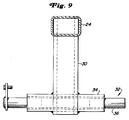
- Fig. 9
- den ersten Teil der Anschlussvorrichtung mit dem ersten Schwenkmechanismus in Seitenansicht,
- Fig. 10
- den zweiten Schwenkmechanismus der Anschlussvorrichtung mit einem aufgesetzten Hebelteil in Seitenansicht,
- Fig. 11
- den dritten Teil der Anschlussvorrichtung mit dem zweiten und dem dritten Schwenkmechanismus,
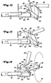
- Fig. 12
- die Anschlussvorrichtung in Arbeitsstellung und in schematischer Darstelllung,
- Fig. 13
- die Anschlussvorrichtung in schematischer Darstellung in einem Zustand, in dem noch keine Verschwenkung um den zweiten Schwenkmechanismus erfolgte und
- Fig. 14
- die Anschlussvorrichtung in schematischer Darstellung in einem Zustand, in dem ein Verschwenken um den zweiten und dritten Schwenkmechanismus stattfindet.
- Fig. 1
- a large-area rotary mower in top view,
- Fig. 2
- the connection device of the side mower in a view from the rear with the mower in its working position,
- Fig. 3
- 2 in a view from the rear and in a position in which the side mower has been adjusted by its first pivot mechanism and in which the pivoting takes place about the second pivot mechanism, parts of a locking device being recognizable,
- Fig. 4
- 2 in a view from above,
- Fig. 5
- the connection device in side view with the right side mower in its working position,
- Fig. 6
- the connection device in side view with the side mower in the transport position,
- Fig. 7
- the second part of the connection device in a view from the rear,
- Fig. 8
- the second part of the connection device in side view,
- Fig. 9
- the first part of the connection device with the first swivel mechanism in side view,
- Fig. 10
- the second pivot mechanism of the connection device with an attached lever part in side view,
- Fig. 11
- the third part of the connection device with the second and the third pivot mechanism,
- Fig. 12
- the connection device in the working position and in a schematic representation,
- Fig. 13
- the connection device in a schematic representation in a state in which no pivoting has yet taken place about the second pivot mechanism and
- Fig. 14
- the connection device in a schematic representation in a state in which pivoting about the second and third pivot mechanism takes place.
Die Fig. 1 bis 14 beziehen sich auf die Anschlussvorrichtungen bzw. auf die Aufhängung 10 für die seitlichen Schneideinheiten eines Großflächen-Sichelmähers. Im einzelnen ist aus Fig. 1 ein selbstfahrendes Gerät 12 erkennbar, das mit einer vorderen Schneideinheit 14 und einer linken und rechten flügelartig angeordneten Schneideinheit 16 und 18 ausgestattet ist. Hydraulikmotore 20 auf den Schneideinheiten dienen zum Antrieb der um vertikale Achsen umlaufenden Sichelmesser 22. Jede Schneideinheit hat mehrere Sichelmesser, so sind bei dem bevorzugten Ausführungsbeispiel an der vorderen Schneideinheit drei und an den beiden seitlichen Schneideinheiten jeweils zwei Sichelmesser erkennbar. Auf diese Weise kann bei Vorwärtsfahrt des für den kommerziellen Einsatz konzipierten Rasenmähers mit einer relativ großen Schnittbreite gemäht werden.1 to 14 relate to the connection devices or to the
Die nachfolgenden Ausführungen befassen sich ausführlich mit der Aufhängung 10 für die rechte Schneideinheit 18 mit dem Verstehen, dass die Aufhängung für die linke Schneideinheit 16 ähnlich, wenn nicht identisch ist. Man erkennt einen an die Schneideinheit 18 angelenkten Armausleger oder Drücketeil 24, der über einen Anschlussmechanismus 26 an die Schneideinheit angeschlossen ist und diese auf dem Boden derart führt, dass die Schneideinheit einmal um eine in Fahrtrichtung oder im wesentlichen in Fahrtrichtung verlaufende Achse nach rechts und nach links und zum anderen um eine quer zur Fahrtrichtung verlaufende und durch einen Anschlusszapfen 28 gebildete Achse nach vorne und nach hinten kippen kann. Außerdem Bat der Anschlussmechanismuss 26 noch so gestaltet, dass bei einem Auftreffen der Schneideinheit auf Hindernisse eine rückwärtige Ausweichbewegung zur Vermeidung von Beschädigungen möglich ist. Einzelheiten des Anschlussmechanismus sind der europäischen Patentanmeldung der Anmelderin vom gleichen Tage, die die Priorität aus der US Anmeldung mit dem Aktenzeichen 648 237 vom 13. Mai 1966 in Anspruch nimmt, zu entnehmen. Auf diese Anmeldung wird ausdrücklich verwiesen.The following explanations deal in detail with the
Der Drücketeil 24 ist über die Aufhängung 10 an das Gerät 12 angeschlossen. Im einzelnen ist das innere Ende des Drücketeils 24 mit einem vertikal nach unten zeigenden ersten Teil 30 fest verbunden, der an seinem unteren Ende an einem Schwenkmechanismus 32, von dem er auch getragen wird, angelenkt ist, wozu er dort mit einer Hülse 34 versehen ist, die von einer ersten Welle 36 drehbar aufgenommen ist. Die erste Welle 36 wiederum ist in Öffnungen 38 aufgenommen, die in einem zweiten Teil 40 vorgesehen sind. Eine drehfeste Verbindung wird dabei dadurch erzielt, dass eine Platte 42 an das eine Ende der ersten Welle 36 angeschweißt ist, die über eine Schraube 44 mit dem zweiten Teil 40 verbunden wird. Der zweite Teil 40 seinerseits ist an einem zweiten Schwenkmechanismus 46, von dem er auch getragen wird, angelenkt. Zu dem zweiten Schwenkmechanismus gehört eine zweite Welle 48, an die endseitig eine Platte 50 angeschweißt ist, die über eine Schraube 52 mit dem zweiten Teil 40 verbunden ist. Aus den Fig. 5 und 6 ist erkennbar, dass die zweite Welle 48 von Öffnungen 54 im zweiten Teil 40 aufgenommen ist und in Öffnungen 56 eines dritten Teils 58 drehbar ist. Der dritte Teil seinerseits ist an einem dritten Schwenkmechanismus 60, von dem er auch getragen wird, angelenkt. Zu dem dritten Schwenkmechanismus 60 gehört eine dritte Welle 62, die sich von dem Fahrzeugrahmen 64 seitlich nach außen erstreckt. Die dritte Welle ist feststehend und mit zwei Lagern 66 versehen, die ein Rohr 68 drehbar lagern. Das Rohr 68 ist mit dem dritten Teil 58 fest verbunden bzw. Bestandteil desselben, so dass der dritte Teil um die Achse der dritten Welle 62 schwenken kann. Über einen Sprengring 70 am Ende der dritten Welle 62 wird das Rohr 68 auf der dritten Welle 62 gesichert.The
Wie bei derartigen Geräten üblich, kann die Schneideinheit aus ihrer Arbeitsstellung in eine Transportstellung hochgeklappt werden. Hierzu ist eine Hubvorrichtung vorgesehen, zu der ein hydraulisch beaufschlagbarer Zylinder 72 gehört. Dieser Zylinder ist mit seinem einen Ende an dem Fahrzeugrahmen 64 und mit seinem anderen Ende an einem Hebeteil 74 angeschlossen, der zwischen seinen Enden auf der zweiten Welle 48 drehbar gelagert ist. Aus Fig. 2 ist erkennbar, dass der Hebeteil L-förmig oder etwa L-förmig ausgebildet ist, wobei an seinem oberen Ende ein Verbindungsstück 76 gelenkig angreift. Das Verbindungsstück 76 ist noch mit einem Langloch 78 versehen, in das ein Zugbolzen 80 eingreift, der mit dem Drücketeil 24 fest verbunden ist. Zu der Hubvorrichtung gehört noch ein Gestängeteil 82, der einenends an dem Fahrzeugrahmen 64 und anderenends an dem zweiten Teil 40 angreift, damit die Schneideinheit in ihrem hochgeklappten Zustand noch nach rückwärts geschwenkt werden kann. Dies wird später noch näher erläutert.As is usual with such devices, the cutting unit can be folded up from its working position into a transport position. For this purpose, a lifting device is provided, to which a hydraulically
Die Schneideinheiten können in ihrer Transportstellung auch verriegelt werden. Die hierzu vorgesehene Verriegelungsvorrichtung 84 weist, wie aus den Fig. 1 bis 4 leicht erkennbar ist, einen an dem Fahrzeugrahmen schwenkbar angeschlossenen Riegel 86 auf, der über eine Torsionsfeder 88 in seine außen liegende Riegelstellung gedrückt wird, in der ein Hakenteil 90 des Riegels in der Transportstellung der Schneideinheit einen Ausleger 92 erfassen kann, der an dem Drücketeil 24 vorgesehen ist. Eine sich bis zu dem Fahrerstand erstreckende Kontrollstange 94 kann in der Verriegelungsstellung, in der der Ausleger mit dem Riegel verriegelt ist, festgestellt werden. Die Kontrollstange lässt sich außerdem noch in einer zweiten Stellung feststellen, in der der Riegel eine Stellung einnimmt, in der er bei hochgeklappter Schneideinheit nicht mit dem Ausleger verriegelt werden kann. Dies ermöglicht der Bedienungsperson die Schneideinheit schnell anzuheben und wieder abzusenken, beispielsweise in solchen Fällen, wenn einem Hindernis ausgewichen werden soll.The cutting units can also be locked in their transport position. The locking
In einem normalen Arbeitseinsatz werden die Schneideinheiten eines derartigen Großflächensichelmähers beim Mähen über eine Vielzahl von Pendelrädern 96 auf dem Boden geführt. Bei einer Vorwärtsfahrt des Gerätes 12 schiebt der an das Gerät 12 angeschlossene Drückearm 24 die zugehörige seitliche Schneideinheit. Bei einem Auftreffen des Gerätes 12 und / oder der Schneideinheiten auf unebenes Gelände können die Schneideinheiten gegenüber dem Gerät Schwenkbewegungen ausführen, so dass der erwünschte ausgezeichnete Rasenschnitt nicht leidet. Im einzelnen kann der Drücketeil 24 um die Achse der ersten Welle 36 bei einem Überfahren von unebenem Gelände schwenken. Hierbei ist darauf hinzuweisen, dass die erste Welle 36 auf gleicher Höhe wie die Schneidmesser 22 angeordnet ist, so dass bei einem Verschwenken der Schneideinheit gegenüber dem Gerät in der Regel kein ungeschnittenes Gras stehenbleibt. Bei einem derartigen Verschwenken verstellt sich der Zugbolzen 80 in dem in dem Verbindungsstück 76 vorgesehenen Langloch 78. Das Langloch ermöglicht der Schneideinheit 18 ein Schwenkbewegung von etwa 18° nach oben und unten aus seiner horizontalen Arbeitsstellung. Bei derartigen Schwenkbewegungen verändert der zweite Teil 40 seine Stellung normalerweise nicht, da er, wie es aus der Fig. 2 ersichtlicht ist, mit seiner hierzu entsprechend ausgebildeten Rückseite gegen das Stirnende der dritten Welle 62 anliegt.In normal work, the cutting units of such a large-area rotary mower are guided on the ground by a plurality of
Die seitlichen Schneideinheiten lassen sich unabhängig voneinander hochklappen, was dann erwünscht ist, wenn eine Seiteneinheit einem Hindernis, beispielsweise einem Baum, ausweichen muss. Die Verstellung in die verriegelbare Transportstellung kann gemeinsam erfolgen. In jedem Falle wird zunächst der entspreche Zylinder 72 für das Hochklappen druckbeaufschlagt. Dabei wird die Kolbenstange ausgefahren, und der Hebelteil 74 verstellt sich aus seiner Stelllung in Fig. 2 entgegen dem Uhrzeigersinn um die Achse der zweiten Welle 48. Das obere Ende des Hebelteils schwenkt mit Bezug auf die Darstellung in Fig. 2 nach links, wobei gleichzeitig des Verbindungsstück 76 nach links mitgenommen wird. Sobald nun das rechte Ende des Langloches 78 gegen den Zugzapfen 80 zur Anlage kommt, wird bei einem weiteren Ausfahren der Kolbenstange des Zylinders 72 der erste Teil 30 zusammen mit dem Drücketeil 24 und der Schneideiheit um die erste Welle 36 entgegen dem Uhrzeigersinn verschwenken, und zwar solange bis der erste Teil 30 sich satt gegen die hierzu entsprechend ausgebildete Stirnseite des zweiten Teils 40 anlegt, wie es in Fig. 3 dargestellt ist. Bei einer Anlage des ersten Teils 30 gegen den zweiten Teil 40 ist eine weitere Verschwenkung entgegen dem Uhrzeigersinn um die erste Welle 36 blockiert. Hieraus resultiert, dass bei einem weiteren Ausfahren der Kolbenstange des Zylinders 72 der erste und der zweite Teil 30 und 40 zusammen mit dem Drücketeil 24 und der Schneideinheit 18 um die Achse der zweiten Welle 48 entgegen dem Uhrzeigersinn nach oben verschwenken.The side cutting units can be folded up independently of one another, which is desirable when a side unit has to avoid an obstacle, for example a tree. The adjustment in the lockable transport position can be done together. In any case, the corresponding
Bei einem solchen Hochklappen wirken der dritte Schwenkmechanismus 60 und der Gestängeteil 82 derart zusammen, dass nach der Anlage des ersten Teils 30 gegen den zweiten Teil 40 die Seiteneinheit 18 nach rückwärts auf der dritten Welle 62 gedreht wird. Aus Fig. 4 ist ersichtlich, dass der relativ starre Gestängeteil 82 sich zwischen dem Punkt A am Fahrzeugrahmen 64 und dem Punkt B am zweiten Teil 40 erstreckt. Dadurch verhindert der Gestängeteil 82, dass der zweite Teil 40 bei einem Hochklappen sich auf der Linie C verstellt. Vielmehr verstellt er sich auf dem Kreisbogen D nach rückwärts, da der Gestängeteil 82 den Abstand zwischen den Punkten A und B konstant hält. Durch die starre Verbindung über den Gestängeteil 82 wird der zweite Teil 40 zusammen mit dem ersten Teil 30 aus seiner Stellung in Fig. 5 entgegen dem Uhrzeigersinn in die Stellung nach Fig. 6 verstellt, wenn die Kolbenstange des Zylinders 72 ausgefahren wird. D. h. bei vollständig ausgefahrener Kolbenstange oder dann, wenn die Seiteneinheit 18 ihre Transportstellung erreicht hat, ist die entsprechende seitliche Schneideinheit nach rückwärts um die Achse der dritten Welle 62 verschwenkt.In the case of such a folding up, the
Zusammenfassend kann also gesagt werden, dass bei einem Hochklappen der Seiteneinheiten zunächst eine Drehbewegung des ersten Teils 30 um die erste Welle 36 erfolgt. Sobald der erste Teil 30 gegen den zweiten Teil 40 anliegt, erfolgt eine Verschwenkung beider Teile 30 und 40 gemeinsam um die Achse der relativ hoch liegenden zweiten Welle 48 nach oben und um die Achse der dritten Welle 62 nach rückwärts. Für diese Bewegungsvorgänge ist lediglich ein Zylinder erforderlich. Alle diese Bewegungsvorgänge sind schematisch nochmals in den Fig. 12 bis 13 angedeutet. Man erkennt auch dort die relativ hochliegende zweite Welle 48, wodurch erreicht wird, dass die Seiteneinheiten im hochgeklappter Transportstellung einen großen Bodenabstand haben.In summary, it can be said that when the side units are folded up, the
Obwohl derartige Großflächensichelmäher eine große Arbeitsbreite aufweisen, ist ihre Bauweise wegen der erforderliche Wendigkeit eher gedrungen. Zwischen den in der Regel antreibbaren vorderen Rädern und den rückwärtigen lenkbaren Rädern müssen ein Fahrerstand für die Bedienungsperson, ein Motor und ein Getriebe untergebracht werden. Damit nun die Seiteneinheiten 16 und 18 im hochgeklappten Zustand den Aufstieg auf den Fahrerstand und / oder die Sicht zur Seite nicht behindern, sind sie in der Transportstellung zusätzlich nach rückwärts verschwenkt.Although such large-area rotary mowers have a large working width, their construction is rather compact due to the maneuverability required. Between the generally drivable front wheels and the rear steerable wheels, a driver's station for the operator, an engine and a transmission must be accommodated. So that the
Bei einem Verstellen der seitlichen Schneideinheiten aus der Transportstellung in die Arbeitsstellung laufen die Vorgänge, die für das Hochklappen beschrieben wurden, im wesentlichen umgekehrt ab. Zum Absenken werden die entsprechenden Zylinder eingefahren, und die Schneideinheiten senken sich infolge ihres Eigengewichtes ab. Der erste und der zweite Teil 30 und 40 drehen zunächst um die Achse der dritten Welle 62 nach vorne und gleichzeitig um die Achse der zweiten Welle 48 nach unten. Sobald der zweite Teil 40 wieder gegen das Stirnende der dritten Welle zur Anlage kommt, ist die Drehbewegung um die Achse der zweiten Welle 48 beendet und die Drehung nach unten um die Achse der ersten Welle 36 kann beginnen.When the lateral cutting units are moved from the transport position into the working position, the processes described for folding up are essentially reversed. The corresponding cylinders are retracted for lowering and the cutting units lower due to their own weight. The first and
Claims (8)
Applications Claiming Priority (2)
| Application Number | Priority Date | Filing Date | Title |
|---|---|---|---|
| US08/645,367 US5715667A (en) | 1996-05-13 | 1996-05-13 | Wing deck mounting and lift mechanism |
| US645367 | 2000-08-24 |
Publications (2)
| Publication Number | Publication Date |
|---|---|
| EP0807377A2 true EP0807377A2 (en) | 1997-11-19 |
| EP0807377A3 EP0807377A3 (en) | 1999-06-16 |
Family
ID=24588725
Family Applications (1)
| Application Number | Title | Priority Date | Filing Date |
|---|---|---|---|
| EP97107538A Withdrawn EP0807377A3 (en) | 1996-05-13 | 1997-05-07 | Device for connecting a height adjustable implement to a vehicle from a working in a transport position |
Country Status (3)
| Country | Link |
|---|---|
| US (1) | US5715667A (en) |
| EP (1) | EP0807377A3 (en) |
| CA (1) | CA2197795A1 (en) |
Cited By (2)
| Publication number | Priority date | Publication date | Assignee | Title |
|---|---|---|---|---|
| DE19951080A1 (en) * | 1999-10-23 | 2001-04-26 | Deere & Co | Self-propelled agricultural vehicle |
| DE102011080385B3 (en) * | 2011-06-10 | 2012-12-06 | Wiedenmann Gmbh | mower |
Families Citing this family (21)
| Publication number | Priority date | Publication date | Assignee | Title |
|---|---|---|---|---|
| US6079193A (en) * | 1999-01-29 | 2000-06-27 | Deere & Company | Implement suspension with lost motion coupling |
| US6223510B1 (en) * | 1999-06-08 | 2001-05-01 | Gary L. Gillins | Mower deck with object tracing capability |
| US6301863B1 (en) * | 1999-11-22 | 2001-10-16 | Eugene J Liebrecht | Multi-blade circumrotational trimmer |
| US6481194B1 (en) | 2000-05-24 | 2002-11-19 | Deere & Company | Cutting implement height adjustment mechanism having grouped height selections |
| IT251364Y1 (en) * | 2000-11-13 | 2003-11-19 | Rotomec Spa | MOWER WITH IMPROVED SYSTEM OF MOWING PLATES |
| US6647705B2 (en) * | 2001-07-09 | 2003-11-18 | Deere & Company | Flex wing rotary cutter having cushioning strut mounted across wing hinge |
| FR2837347B1 (en) | 2002-03-21 | 2004-07-30 | Kuhn Sa | AGRICULTURAL MOWER COMPRISING A CARRIER VEHICLE AND SEVERAL WORKING UNITS |
| DE10228880B4 (en) * | 2002-06-27 | 2005-09-08 | Jakob Voets Ing. Grad. Gmbh & Co. Kg Rheinische Landschaftspflege | Mowing device for lawn and landscape meadow maintenance with a device for receiving and shredding crops |
| US6901728B2 (en) | 2002-12-10 | 2005-06-07 | Gary L. Kelderman | Expanding and contracting implements |
| ITRE20030108A1 (en) * | 2003-11-12 | 2005-05-13 | Gianni Ferrari S R L | MOWER WITH SIDE CUTTING PLATES. |
| US7313902B1 (en) | 2004-09-14 | 2008-01-01 | Commercial Turf Products, Ltd. | Folding deck mechanism |
| FR2881609B1 (en) * | 2005-02-09 | 2007-03-09 | Kuhn Sa Sa | AGRICULTURAL ENGINE FOR THE CUTTING OF PRODUCTS COMPRISING A CARRIER VEHICLE AND WORKING UNITS |
| US7478519B2 (en) * | 2005-10-13 | 2009-01-20 | Deere & Company | Mounting rotary cutting deck to lift arm |
| US7401456B2 (en) * | 2005-11-08 | 2008-07-22 | Deere & Company | Horizontally retractable mower deck |
| CA2585274C (en) * | 2007-04-10 | 2011-07-19 | Stanley J. Boyko | Rotary mower over-center self-locking wing lift |
| US20100192533A1 (en) * | 2009-01-30 | 2010-08-05 | John Coleman | Turf treatment apparatus with floating head suspended from a frame |
| US20100313536A1 (en) * | 2009-06-11 | 2010-12-16 | Ron Berko | Double cut lawnmower attachment |
| US20140223878A1 (en) * | 2013-02-08 | 2014-08-14 | Robert Sassone | Lawn Mower Assemblies |
| JP5940623B2 (en) * | 2014-10-21 | 2016-06-29 | 株式会社Ihiシバウラ | Lawn mower |
| US10980176B1 (en) * | 2018-12-06 | 2021-04-20 | Gerald H. Schreurs | Minimal radius system for cutting vegetation |
| US11147209B1 (en) * | 2021-04-01 | 2021-10-19 | Ataco Steel Products Corp. | Riding lawn mower |
Family Cites Families (13)
| Publication number | Priority date | Publication date | Assignee | Title |
|---|---|---|---|---|
| US3500619A (en) * | 1967-04-24 | 1970-03-17 | Fmc Corp | Sectionalized mower |
| US3736735A (en) * | 1971-07-14 | 1973-06-05 | Deere & Co | Mechanism for retaining the wing section of an implement in its raised position |
| US4573306A (en) * | 1980-07-01 | 1986-03-04 | E. E. White | Beltless swingarm mower |
| US4497160A (en) * | 1983-04-29 | 1985-02-05 | Excel Industries, Inc. | Mower with lateral extension wings |
| US4869057A (en) * | 1987-05-26 | 1989-09-26 | Mtd Products Inc. | Mower deck height and angle control |
| US4742671A (en) * | 1987-08-17 | 1988-05-10 | New Holland Inc. | Crop harvesting machine base unit lift mechanism providing auxiliary height boost to crop gathering attachment |
| US4854112A (en) * | 1987-09-04 | 1989-08-08 | The Toro Company | Turf maintenance apparatus |
| US4864805A (en) * | 1987-09-04 | 1989-09-12 | The Toro Company | System for supporting a working unit |
| FR2635433B1 (en) * | 1988-08-18 | 1991-02-01 | Kuhn Sa | IMPROVED CHASSIS MOWER |
| US5069022A (en) * | 1990-09-28 | 1991-12-03 | Befco, Inc. | Gang mower apparatus |
| US5241808A (en) * | 1992-04-10 | 1993-09-07 | Schulte Industries Ltd. | Wing lifting mechanism for rotary mowers |
| US5381647A (en) * | 1993-10-28 | 1995-01-17 | Trail-Buster Dozer, Inc. | ATV mower articulating hitch |
| US5463853A (en) * | 1994-08-22 | 1995-11-07 | Santoli; Domenico | Lawnmower with adjustable side cutters |
-
1996
- 1996-05-13 US US08/645,367 patent/US5715667A/en not_active Expired - Fee Related
-
1997
- 1997-02-17 CA CA002197795A patent/CA2197795A1/en not_active Abandoned
- 1997-05-07 EP EP97107538A patent/EP0807377A3/en not_active Withdrawn
Cited By (2)
| Publication number | Priority date | Publication date | Assignee | Title |
|---|---|---|---|---|
| DE19951080A1 (en) * | 1999-10-23 | 2001-04-26 | Deere & Co | Self-propelled agricultural vehicle |
| DE102011080385B3 (en) * | 2011-06-10 | 2012-12-06 | Wiedenmann Gmbh | mower |
Also Published As
| Publication number | Publication date |
|---|---|
| EP0807377A3 (en) | 1999-06-16 |
| CA2197795A1 (en) | 1997-11-14 |
| US5715667A (en) | 1998-02-10 |
Similar Documents
| Publication | Publication Date | Title |
|---|---|---|
| EP0475021B1 (en) | Mower, especially front-mounted mower | |
| EP0807377A2 (en) | Device for connecting a height adjustable implement to a vehicle from a working in a transport position | |
| DE2053073C3 (en) | mower | |
| EP1106051A1 (en) | Mower | |
| DE3326297A1 (en) | VEHICLE WITH VIBRATION LIMIT | |
| DE69300977T2 (en) | Hay machine with dynamic relief device | |
| DE60205226T2 (en) | Brush cutters vehicle | |
| DE10321683B4 (en) | Post free mower and method of using the free mower | |
| EP1266551B1 (en) | Working machine for mounting on a vehicle | |
| DE60112351T2 (en) | Hay-making machine | |
| EP0807376A2 (en) | Collision-safety for a mower connectable to a vehicle | |
| DE1482095C3 (en) | mower | |
| DE4108449C2 (en) | ||
| DE4314250C1 (en) | Rotor head mower attachment with wide swathe | |
| DE4142496C2 (en) | Haymaking machine | |
| EP0289864A1 (en) | Hay making machine | |
| DE3835367C2 (en) | Device for mowers for ground adaptation of the cutting units | |
| EP0469351A1 (en) | Device for attaching a front mounted mower to a motor vehicle | |
| DE2529928C2 (en) | Attachment device for an agricultural machine | |
| DE3106929A1 (en) | Front-mounted mower with cutting knives moving to and fro | |
| DE3713474A1 (en) | HAY ADVERTISING MACHINE | |
| DE4103011C2 (en) | Mower or hay machine | |
| DE2230245A1 (en) | MOWER | |
| DE9414597U1 (en) | Drawn mower | |
| DE4121088B4 (en) | Hay-making machine |
Legal Events
| Date | Code | Title | Description |
|---|---|---|---|
| PUAI | Public reference made under article 153(3) epc to a published international application that has entered the european phase |
Free format text: ORIGINAL CODE: 0009012 |
|
| AK | Designated contracting states |
Kind code of ref document: A2 Designated state(s): DE FR GB IE IT |
|
| PUAL | Search report despatched |
Free format text: ORIGINAL CODE: 0009013 |
|
| AK | Designated contracting states |
Kind code of ref document: A3 Designated state(s): DE FR GB IE IT |
|
| RIC1 | Information provided on ipc code assigned before grant |
Free format text: 6A 01D 75/30 A, 6A 01B 73/04 B |
|
| STAA | Information on the status of an ep patent application or granted ep patent |
Free format text: STATUS: THE APPLICATION IS DEEMED TO BE WITHDRAWN |
|
| 18D | Application deemed to be withdrawn |
Effective date: 19991201 |