EP0807206B1 - Moteur a combustion interne - Google Patents
Moteur a combustion interne Download PDFInfo
- Publication number
- EP0807206B1 EP0807206B1 EP96900280A EP96900280A EP0807206B1 EP 0807206 B1 EP0807206 B1 EP 0807206B1 EP 96900280 A EP96900280 A EP 96900280A EP 96900280 A EP96900280 A EP 96900280A EP 0807206 B1 EP0807206 B1 EP 0807206B1
- Authority
- EP
- European Patent Office
- Prior art keywords
- cam
- eccentric
- internal combustion
- combustion engine
- eccentric element
- Prior art date
- Legal status (The legal status is an assumption and is not a legal conclusion. Google has not performed a legal analysis and makes no representation as to the accuracy of the status listed.)
- Expired - Lifetime
Links
- 238000002485 combustion reaction Methods 0.000 title claims description 24
- 230000005540 biological transmission Effects 0.000 claims description 7
- 238000005553 drilling Methods 0.000 description 4
- 238000006073 displacement reaction Methods 0.000 description 3
- 230000033228 biological regulation Effects 0.000 description 1
- 230000003247 decreasing effect Effects 0.000 description 1
- 230000000694 effects Effects 0.000 description 1
- 238000004519 manufacturing process Methods 0.000 description 1
- 230000001360 synchronised effect Effects 0.000 description 1
Images

Classifications
-
- F—MECHANICAL ENGINEERING; LIGHTING; HEATING; WEAPONS; BLASTING
- F01—MACHINES OR ENGINES IN GENERAL; ENGINE PLANTS IN GENERAL; STEAM ENGINES
- F01L—CYCLICALLY OPERATING VALVES FOR MACHINES OR ENGINES
- F01L1/00—Valve-gear or valve arrangements, e.g. lift-valve gear
- F01L1/34—Valve-gear or valve arrangements, e.g. lift-valve gear characterised by the provision of means for changing the timing of the valves without changing the duration of opening and without affecting the magnitude of the valve lift
- F01L1/344—Valve-gear or valve arrangements, e.g. lift-valve gear characterised by the provision of means for changing the timing of the valves without changing the duration of opening and without affecting the magnitude of the valve lift changing the angular relationship between crankshaft and camshaft, e.g. using helicoidal gear
- F01L1/34413—Valve-gear or valve arrangements, e.g. lift-valve gear characterised by the provision of means for changing the timing of the valves without changing the duration of opening and without affecting the magnitude of the valve lift changing the angular relationship between crankshaft and camshaft, e.g. using helicoidal gear using composite camshafts, e.g. with cams being able to move relative to the camshaft
-
- F—MECHANICAL ENGINEERING; LIGHTING; HEATING; WEAPONS; BLASTING
- F01—MACHINES OR ENGINES IN GENERAL; ENGINE PLANTS IN GENERAL; STEAM ENGINES
- F01L—CYCLICALLY OPERATING VALVES FOR MACHINES OR ENGINES
- F01L1/00—Valve-gear or valve arrangements, e.g. lift-valve gear
- F01L1/34—Valve-gear or valve arrangements, e.g. lift-valve gear characterised by the provision of means for changing the timing of the valves without changing the duration of opening and without affecting the magnitude of the valve lift
- F01L1/344—Valve-gear or valve arrangements, e.g. lift-valve gear characterised by the provision of means for changing the timing of the valves without changing the duration of opening and without affecting the magnitude of the valve lift changing the angular relationship between crankshaft and camshaft, e.g. using helicoidal gear
- F01L1/356—Valve-gear or valve arrangements, e.g. lift-valve gear characterised by the provision of means for changing the timing of the valves without changing the duration of opening and without affecting the magnitude of the valve lift changing the angular relationship between crankshaft and camshaft, e.g. using helicoidal gear making the angular relationship oscillate, e.g. non-homokinetic drive
Definitions
- the invention relates to an internal combustion engine in which the speed of rotation of a cam Gas exchange control is cyclically changeable by a Intermediate link in a plane perpendicular to the axis of rotation a camshaft slidable and in any position is rotatable within this plane.
- Such a rotary drive arrangement is preferably used for driving cams to control an intake or Exhaust valve of an internal combustion engine.
- the degree of change i.e. the amount of temporary increase in angular velocity and temporarily lowering the angular velocity of the Nockens and the phase of these changes depend on the position that an intermediate link has with respect to a Driveshaft. With a concentric position of the Intermediate link with respect to the drive shaft rotates the cam synchronous with the drive shaft.
- the object of the invention is such Engine to run so that the mechanism to cause the cyclical change of the Rotation speed of the cam is compact, inexpensive and easy to manufacture, one stiff storage of the component enables and by simple control means can be actuated.
- the invention based on a common Inner eccentric two separate outer eccentrics are stored, is particularly suitable for an internal combustion engine a camshaft that is both intake and Exhaust valves drives. This can be a special compact structure can be achieved.
- the control or Rotation of the inner eccentric and the two External eccentric can have appropriate sprockets take place, the outer eccentrics either separately or can be controlled together.
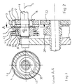
- a rotary drive arrangement that is cyclical generates variable cam movement, has a shaft 1 with a central axis 5, which in the in the first to 3 shown embodiment of a drive shaft 1st corresponds to these rotary drive regulations.
- an inner eccentric 30 is mounted, with a for storage Needle roller bearings can be used.
- the inner eccentric 30 by means of a Thrust washer 38 and a snap ring 39 against Be secured to the left in Fig. 2.
- the inner eccentric 30 has a base body 31 and an eccentric seat 32, through which a bore 33 for receiving the shaft 1 runs.
- the base body 31 has a circular outer contour 37, the central axis of which coincides with the central axis 5 of the shaft 1, which is also the axis of rotation.
- the outer contour 35 of the eccentric seat 32 has a central axis which is offset by a first eccentricity e 1 with respect to the central axis of the bore 33 and thus with respect to the axis of rotation 5.
- An outer eccentric 40 is rotatable on the outer contour 35 stored.
- the outer eccentric 40 has a bore 41, those for receiving the outer contour 35 of the eccentric seat 32 the inner eccentric 30 is used.
- the outer contour 45 of the outer eccentric 40 is offset from the central axis of the bore 41 by a second eccentricity e 2 .
- the eccentricities e 1 and e 2 can be chosen freely, but are preferably the same in amount.
- An inner eccentric ring gear 34 is non-rotatable with the Outer contour 37 of the inner eccentric 30 connected.
- an outer eccentric ring gear 44 arranged, the rotatable on the outer contour 37 of the Inner eccentric 30 is mounted.
- the External eccentric ring gear 44 has a nose 43 (see FIG. 2), which in a groove 46 of the outer eccentric 40th intervenes.
- Rotary drive means (not shown) for controlling the respective rotational position of the inner eccentric 30 and the Outer eccentric 40 can be in the inner eccentric ring gear 34 and engage the external eccentric ring gear 44.
- control means for example, two stepper motors selected, the rotary positions of the Inner eccentric 30 and the outer eccentric 40 separately and adjust independently of each other so that the outer contour 45 of the outer eccentric 40 any position within a plane perpendicular to the central axis 5 of the shaft 1 can take.
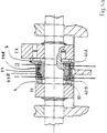
- This intermediate link 4th has a first sliding guide 6 and a second Slideway 7, each for receiving a Slide block 13 are suitable.
- a first rotating body 2 is rotatably connected to the drive shaft 1 and points a start-up band 2a.
- On the first rotating body 2 is a formed as a gear second rotating body 3 rotatable stored.
- the first rotating body 2 has a Bore 11 into which a first designed as a pin Transmission element 8 is introduced. This pin 8 transmits the rotation of the first rotating body 2 via one the sliding blocks 13 and the first sliding guide 6 on the Intermediate link 4.
- the second rotating body 3 has a bore 12, in the second designed as a pen Transmission element 9 is introduced.
- the rotation of the Intermediate member 4 is on the second sliding guide 7 and the other of the two sliding blocks 13 and the pin 9 transferred to the second rotating body 3.
- the external eccentric ring gear 44 can extend axially over the External eccentric 40, the intermediate member 4 and the second Support the rotating body 3 against the collar 2a.
- the federal government 2a first rotating body 2 thus causes the entire Rotary drive arrangement against a shift to the right is secured in Fig. 2.
- the second rotating body 3 is designed as a gear that is engaged with a cam gear 22 so that the Rotation of the second rotating body 3 on the camshaft 21 and transmit the cam 20 connected to it in a rotationally fixed manner becomes.
- the intermediate member 4 is in a position in which its central or rotational axis coincides with the central or rotational axis 5 of the drive shaft 1, the second rotary body 3 and thus the cam 20 rotate synchronously with the drive shaft 1 Position is reached when the eccentricities e 1 and e 2 are equal in amount and the inner eccentric 30 and the outer eccentric 40 assume such a position that the two eccentricities e 1 and e 2 are diametrically opposed.
- a complete revolution of the drive shaft 1 has continue one full turn of the second Rotating body 3 and the cam 20 result in the course of this entire turn, however, there is one temporary increase in rotation speed and too a temporary decrease in the rotational speed of the second rotating body 3 and thus the cam 20.
- Das Extent of this increase in rotational speed or Rotation speed reduction depends on the offset of the Axis of rotation of the intermediate member 4 with respect to the central axis 5 of the drive shaft 1. The direction of this offset determines the phase position of the respective increase in rotational speed or reduction in rotational speed regarding the position of the cam 20.
- FIG. 4a shows an embodiment of the invention. This differs from that explained above Rotary drive arrangement in that on a common Inner eccentric 30 two outer eccentrics 40A, 40B arranged are.
- the inner eccentric 30 can Inner eccentric ring gear 34 are rotated while the External eccentric 40A, 40B over corresponding External eccentric gear rings 44A, 44B either separately or can be controlled together.
- On each of the two An intermediate member 4 is mounted on the outer eccentric 40A, 40B.
- the internal combustion engine Possibility of variation of the two valves in the case given in which the two outer eccentrics 40A, 40B can be controlled or rotated together. This will compared to the case of independent control of both External eccentric 40A, 40B a control means (not shown) saved.
- the cyclical change in the rotational speed results from the fact that, due to the axial offset of the central axes of rotation of the camshaft and the intermediate member, depending on the angular position, different driving radii r occur between the camshaft and the intermediate member on the one hand and the intermediate member and the cam on the other hand.
- the condition that the tangential speed component v tan must be constant at a constant rotational speed w NW also applies because the distance r NW of this point of engagement from the axis of rotation of the camshaft always remains constant.
- the intermediate member and thus also the Cams once with a full revolution of the camshaft faster and once slower than the camshaft.
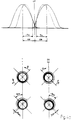
- the lead or lag of the cam opposite the camshaft is zero. Cut at this point the output valve lift curve, i.e. the Valve lift curve, which is at a concentric Position of the intermediate link, and the modified valve lift curve, i.e. the Valve lift curve, which at the respective Axial offset between the axis of rotation of the intermediate link and the axis of rotation of the camshaft.
- Fig. 4b shows the valve lift curves in the on the Field of internal combustion engines usual representation, where OT is the top dead center of the piston, AM is the distance between the middle of the outlet and TDC, i.e. the outlet spread, and EM the distance between the center of the inlet and TDC, i.e. the Intake spread is.
- Phase angle ⁇ is the angle between the maximum of modified cam speed, i.e. the Intersection of the respective output valve lift curve with the modified valve lift curve, and the Output valve lift curve maximum. Positive values of the phase angle ⁇ mean that the modified Valve lift curve in the direction of increasing Cam flank is shifted, and mean negative values a shift towards the falling cam flank.
- the value of the phase angle ⁇ IN of the intake cam IN is preferably positive and the value of the phase angle ⁇ EX of the exhaust cam EX is preferably negative.
- the phase angle is determined by the choice the direction of displacement of the eccentricity with the respective position of the cam tip to the Valve actuator, for example one Tappet.
- Such a configuration is schematic in Fig. 4b shown, the representation under I den Inlet cam and the representation under II den Exhaust cam affects.
- the center white circle represents the Camshaft, the black surface the inner eccentric and the hatched area represents the external eccentric.
- the eccentricity e 1 of the eccentric seat for the inlet cam IN of the common inner eccentric runs approximately 45 ° downward to the left and the eccentricity e 2 of the outer eccentric 40B runs exactly in the opposite direction, so in the starting position that in this starting position the resulting eccentricity e for the intermediate member of the inlet cam IN is zero.
- the eccentricity e 1 of the eccentric seat for the exhaust cam EX of the common inner eccentric extends from the axis of rotation of the camshaft approximately 45 ° to the top left and the eccentricity e 2 of the outer eccentric 40A runs exactly in the opposite direction, so that in this starting position the resulting eccentricity e for the intermediate member of the exhaust cam EX is also zero.
- the angles ⁇ IN and ⁇ EX therefore have a different sign.
Landscapes
- Engineering & Computer Science (AREA)
- Mechanical Engineering (AREA)
- General Engineering & Computer Science (AREA)
- Valve Device For Special Equipments (AREA)
- Valve-Gear Or Valve Arrangements (AREA)
Claims (9)
- Moteur à combustion dans lequel la vitesse de rotation d'une came pour la commande d'échange de gaz est variable de façon cyclique,de sorte que la came est tournée de façon cyclique par rapport à l'arbre à cames lors d'une rotation de l'arbre à cames quand l'axe de rotation de l'élément intermédiaire (4) est déplacé par rapport à l'axe de rotation de l'arbre à cames, comprenantavec un arbre à cames comprenant un axe de rotation,avec une came logée de façon rotative sur l'arbre à cames,avec un élément intermédiaire (4) déplaçable dans un plan perpendiculaire par rapport à l'axe de rotation de l'arbre à cames, cet élément étant logé de façon rotative dans chaque position dans ce plan et comprenant un premier guidage à glissement et un deuxième guidage à glissement,avec un premier élément de transmission qui relie l'arbre à cames avec le premier guidage à glissement pour la transmission du mouvement rotatif de l'arbre à cames à l'élément intermédiaire (4), etavec un deuxième élément de transmission qui relie la came avec le deuxième guidage à glissement pour la transmission du mouvement rotatif de l'élément intermédiaire (4) à la came,caractérisé en ce que deux excentriques périphériques (40A, 40B) sont disposés sur un excentrique intérieur (30).un excentrique intérieur (30) logé de façon rotative sur l'arbre à cames etun excentrique périphérique (40) logé de façon rotative sur l'excentrique intérieur (30), l'élément intermédiaire (4) étant logé de façon rotative sur l'excentrique périphérique (40),
- Moteur à combustion selon la revendication 1, caractérisé en ce que la deuxième excentricité (e2) de l'excentrique périphérique (40) est égale à la première excentricité (e1) de l'excentrique intérieur (30).
- Moteur à combustion selon une des revendications précédentes, caractérisé en ce que l'excentrique intérieur (30) présente une couronne dentée d'excentrique intérieur (34) reliée avec celui-ci de façon résistante à la torsion.
- Moteur à combustion selon une des revendications précédentes, caractérisé en ce que l'excentrique intérieur (30) présente un contour extérieur circulaire (37) dont l'axe central coïncide avec l'axe central de l'alésage (33) recevant l'arbre à cames et qu'une couronne dentée d'excentrique périphérique (44) pour la commande de l'excentrique périphérique (40) est logée sur le contour extérieur (37).
- Moteur à combustion selon la revendication 4, caractérisé en ce que la couronne dentée d'excentrique périphérique (44) présente un nez (43) s'engageant dans une rainure (46) de l'excentrique périphérique (40).
- Moteur à combustion selon une des revendications précédentes, caractérisé en ce qu'un des excentriques périphériques (40A) est couplé avec une came d'admission (IN) et l'autre excentrique périphérique (40B) avec une came d'émission (EX).
- Moteur à combustion selon une des revendications précédentes, caractérisé en ce que tous les deux excentriques périphériques (40A, 40B) peuvent être commandés ensemble.
- Moteur à combustion selon la revendication 7, caractérisé en ce que les deux sièges d'excentrique de l'excentrique intérieur commun (30) sont disposés de telle façon l'un par rapport à l'autre et que les deux excentriques périphériques (40A, 40B) sont disposés de telle façon sur les deux sièges d'excentrique de l'excentrique intérieur commun que les courbes de levage de soupape ont une allure opposée en cas d'une torsion opposée de tous les deux excentriques périphériques (40A, 40B) d'un côté et de l'excentrique intérieur commun (30) de l'autre côté.
- Moteur à combustion selon une des revendications précédentes, caractérisé en ce qu'on peut obtenir une torsion opposée avec un seul moteur de commande par l'emploi d'une paire de pignons droits balayant ensemble, un des pignons droits étant relié avec l'excentrique intérieur et l'autre pignon avec le ou les excentriques périphériques.
Applications Claiming Priority (3)
| Application Number | Priority Date | Filing Date | Title |
|---|---|---|---|
| DE19502834A DE19502834A1 (de) | 1995-01-30 | 1995-01-30 | Anordnung zur Lagerung eines Bauteils |
| DE19502834 | 1995-01-30 | ||
| PCT/DE1996/000056 WO1996023964A1 (fr) | 1995-01-30 | 1996-01-17 | Moteur a combustion interne |
Publications (2)
| Publication Number | Publication Date |
|---|---|
| EP0807206A1 EP0807206A1 (fr) | 1997-11-19 |
| EP0807206B1 true EP0807206B1 (fr) | 2000-03-29 |
Family
ID=7752638
Family Applications (1)
| Application Number | Title | Priority Date | Filing Date |
|---|---|---|---|
| EP96900280A Expired - Lifetime EP0807206B1 (fr) | 1995-01-30 | 1996-01-17 | Moteur a combustion interne |
Country Status (4)
| Country | Link |
|---|---|
| EP (1) | EP0807206B1 (fr) |
| AU (1) | AU4384896A (fr) |
| DE (2) | DE19502834A1 (fr) |
| WO (1) | WO1996023964A1 (fr) |
Families Citing this family (7)
| Publication number | Priority date | Publication date | Assignee | Title |
|---|---|---|---|---|
| DE19629881A1 (de) * | 1996-07-24 | 1998-01-29 | Bayerische Motoren Werke Ag | Ventiltrieb einer Brennkraftmaschine mit sich an einer Exzenterwelle abstützenden Schwinghebeln |
| DE10054798B4 (de) | 2000-11-04 | 2009-03-05 | Schaeffler Kg | Elektrisch angetriebene Vorrichtung zur Drehwinkelverstellung einer Welle gegenüber ihrem Antrieb |
| DE10317508A1 (de) * | 2003-04-16 | 2004-11-04 | Daimlerchrysler Ag | Vorrichtung zum Verstellen des Drehwinkels einer Nockenwelle gegenüber dem Drehwinkel einer Kurbelwelle einer Brennkraftmaschine |
| US20080017150A1 (en) * | 2004-09-15 | 2008-01-24 | Yamaha Hatsudoki Kabushiki Kaisha | Variable Valve Drive Device, Engine, and Motorcycle |
| DE102005034777B3 (de) * | 2005-07-26 | 2007-03-22 | Daimlerchrysler Ag | Nockenwelle |
| DE102005053119A1 (de) * | 2005-11-08 | 2007-05-10 | Robert Bosch Gmbh | Vorrichtung zur Verstellung der relativen Drehwinkellage zwischen Nockenwelle und Antriebsrad |
| CN111852813A (zh) * | 2020-07-02 | 2020-10-30 | 王彦彬 | 一种直线运动输出机构 |
Family Cites Families (6)
| Publication number | Priority date | Publication date | Assignee | Title |
|---|---|---|---|---|
| US3633555A (en) * | 1969-06-27 | 1972-01-11 | Ass Eng Ltd | Variable camshaft mechanism |
| GB1311562A (en) * | 1969-06-27 | 1973-03-28 | Ass Eng Ltd | Device for moving a cam relative to its driving shaft |
| GB2133465A (en) * | 1982-12-24 | 1984-07-25 | Ford Motor Co | I.c. engine camshaft drive mechanism |
| GB2268570B (en) * | 1989-10-13 | 1994-03-30 | Rover Group | An internal combustion engine camshaft drive mechanism |
| JP2644408B2 (ja) * | 1991-03-29 | 1997-08-25 | アーウィン コロステンスキー | 内燃機関の連続可変バルブタイミング機構 |
| JP3177532B2 (ja) * | 1992-01-27 | 2001-06-18 | 株式会社ユニシアジェックス | 内燃機関の吸排気弁駆動制御装置 |
-
1995
- 1995-01-30 DE DE19502834A patent/DE19502834A1/de not_active Withdrawn
-
1996
- 1996-01-17 AU AU43848/96A patent/AU4384896A/en not_active Withdrawn
- 1996-01-17 DE DE59604840T patent/DE59604840D1/de not_active Expired - Fee Related
- 1996-01-17 EP EP96900280A patent/EP0807206B1/fr not_active Expired - Lifetime
- 1996-01-17 WO PCT/DE1996/000056 patent/WO1996023964A1/fr not_active Ceased
Also Published As
| Publication number | Publication date |
|---|---|
| EP0807206A1 (fr) | 1997-11-19 |
| DE19502834A1 (de) | 1996-08-08 |
| AU4384896A (en) | 1996-08-21 |
| DE59604840D1 (de) | 2000-05-04 |
| WO1996023964A1 (fr) | 1996-08-08 |
Similar Documents
| Publication | Publication Date | Title |
|---|---|---|
| DE19680481C2 (de) | Variabler Ventiltrieb | |
| DE69508202T2 (de) | Nockenphasenvariator und Verfahren zu dessen Zusammenbau | |
| DE3442608A1 (de) | Kurbelschleifen-brennkraftmaschine mit veraenderlichem hub und verdichtungsverhaeltnis | |
| DE69412727T2 (de) | Automatische Verstellvorrichtung zur Verstellung der Ventilsteuerzeiten | |
| EP0521412B1 (fr) | Moteur à combustion interne avec culbuteur pour la commande de soupape | |
| DE69012828T2 (de) | Nockenwellensteuermechanismus für brennkraftmotoren. | |
| DE60300177T2 (de) | Variabler Nockenversteller mit Schneckengetriebe | |
| DE4419557C1 (de) | Brennkraftmaschine mit variabler Ventilsteuerung | |
| DE68925342T2 (de) | Ventilantriebsvorrichtung für Brennkraftmaschine | |
| EP0807206B1 (fr) | Moteur a combustion interne | |
| DE19821228A1 (de) | Ventilsteuervorrichtung für einen Verbrennungsmotor | |
| DE69613493T2 (de) | Einstellvorrichtung zur Veränderung der Phase für Drehelemente | |
| DE19702670A1 (de) | Variable Ventilsteuerung für Brennkraftmaschinen | |
| DE19502836C2 (de) | Brennkraftmaschine | |
| DE4413406C2 (de) | Brennkraftmaschine mit variabler Ventilsteuerung | |
| DE4036010A1 (de) | Verstellbarer nockenwellenantrieb fuer eine brennkraftmaschine | |
| DE4413443C2 (de) | Brennkraftmaschine | |
| EP0048321B1 (fr) | Moteur polycylindrique à piston et à soupapes commandées | |
| DE68901763T2 (de) | Mechanismus zur uebertragung einer drehbewegung von einer welle auf eine andere. | |
| DE19544412C1 (de) | Ventiltrieb einer Brennkraftmaschine | |
| DE3802528A1 (de) | Drehzahlreduktionseinrichtung | |
| DE19501172C2 (de) | Drehantriebsanordnung | |
| EP1128029B1 (fr) | Dispositif de distribution variable pour moteur à combustion interne | |
| DE19539901C2 (de) | Brennkraftmaschine | |
| WO1995028554A1 (fr) | Moteur a combustion interne a commande variable des soupapes |
Legal Events
| Date | Code | Title | Description |
|---|---|---|---|
| PUAI | Public reference made under article 153(3) epc to a published international application that has entered the european phase |
Free format text: ORIGINAL CODE: 0009012 |
|
| 17P | Request for examination filed |
Effective date: 19970822 |
|
| AK | Designated contracting states |
Kind code of ref document: A1 Designated state(s): DE FR GB IT |
|
| 17Q | First examination report despatched |
Effective date: 19990423 |
|
| GRAG | Despatch of communication of intention to grant |
Free format text: ORIGINAL CODE: EPIDOS AGRA |
|
| GRAG | Despatch of communication of intention to grant |
Free format text: ORIGINAL CODE: EPIDOS AGRA |
|
| GRAH | Despatch of communication of intention to grant a patent |
Free format text: ORIGINAL CODE: EPIDOS IGRA |
|
| GRAH | Despatch of communication of intention to grant a patent |
Free format text: ORIGINAL CODE: EPIDOS IGRA |
|
| GRAA | (expected) grant |
Free format text: ORIGINAL CODE: 0009210 |
|
| AK | Designated contracting states |
Kind code of ref document: B1 Designated state(s): DE FR GB IT |
|
| PG25 | Lapsed in a contracting state [announced via postgrant information from national office to epo] |
Ref country code: IT Free format text: LAPSE BECAUSE OF FAILURE TO SUBMIT A TRANSLATION OF THE DESCRIPTION OR TO PAY THE FEE WITHIN THE PRE;WARNING: LAPSES OF ITALIAN PATENTS WITH EFFECTIVE DATE BEFORE 2007 MAY HAVE OCCURRED AT ANY TIME BEFORE 2007. THE CORRECT EFFECTIVE DATE MAY BE DIFFERENT FROM THE ONE RECORDED.SCRIBED TIME-LIMIT Effective date: 20000329 Ref country code: GB Free format text: LAPSE BECAUSE OF FAILURE TO SUBMIT A TRANSLATION OF THE DESCRIPTION OR TO PAY THE FEE WITHIN THE PRESCRIBED TIME-LIMIT Effective date: 20000329 Ref country code: FR Free format text: LAPSE BECAUSE OF FAILURE TO SUBMIT A TRANSLATION OF THE DESCRIPTION OR TO PAY THE FEE WITHIN THE PRESCRIBED TIME-LIMIT Effective date: 20000329 |
|
| REF | Corresponds to: |
Ref document number: 59604840 Country of ref document: DE Date of ref document: 20000504 |
|
| EN | Fr: translation not filed | ||
| GBV | Gb: ep patent (uk) treated as always having been void in accordance with gb section 77(7)/1977 [no translation filed] |
Effective date: 20000329 |
|
| PLBE | No opposition filed within time limit |
Free format text: ORIGINAL CODE: 0009261 |
|
| STAA | Information on the status of an ep patent application or granted ep patent |
Free format text: STATUS: NO OPPOSITION FILED WITHIN TIME LIMIT |
|
| 26N | No opposition filed | ||
| PGFP | Annual fee paid to national office [announced via postgrant information from national office to epo] |
Ref country code: DE Payment date: 20050722 Year of fee payment: 10 |
|
| PG25 | Lapsed in a contracting state [announced via postgrant information from national office to epo] |
Ref country code: DE Free format text: LAPSE BECAUSE OF NON-PAYMENT OF DUE FEES Effective date: 20060801 |