EP0806384A2 - Fördersystem - Google Patents
Fördersystem Download PDFInfo
- Publication number
- EP0806384A2 EP0806384A2 EP97202370A EP97202370A EP0806384A2 EP 0806384 A2 EP0806384 A2 EP 0806384A2 EP 97202370 A EP97202370 A EP 97202370A EP 97202370 A EP97202370 A EP 97202370A EP 0806384 A2 EP0806384 A2 EP 0806384A2
- Authority
- EP
- European Patent Office
- Prior art keywords
- trolley
- conveying system
- goods
- discharge station
- closing means
- Prior art date
- Legal status (The legal status is an assumption and is not a legal conclusion. Google has not performed a legal analysis and makes no representation as to the accuracy of the status listed.)
- Withdrawn
Links
Images

Classifications
-
- B—PERFORMING OPERATIONS; TRANSPORTING
- B65—CONVEYING; PACKING; STORING; HANDLING THIN OR FILAMENTARY MATERIAL
- B65G—TRANSPORT OR STORAGE DEVICES, e.g. CONVEYORS FOR LOADING OR TIPPING, SHOP CONVEYOR SYSTEMS OR PNEUMATIC TUBE CONVEYORS
- B65G17/00—Conveyors having an endless traction element, e.g. a chain, transmitting movement to a continuous or substantially-continuous load-carrying surface or to a series of individual load-carriers; Endless-chain conveyors in which the chains form the load-carrying surface
- B65G17/002—Conveyors having an endless traction element, e.g. a chain, transmitting movement to a continuous or substantially-continuous load-carrying surface or to a series of individual load-carriers; Endless-chain conveyors in which the chains form the load-carrying surface comprising load carriers resting on the traction element
-
- B—PERFORMING OPERATIONS; TRANSPORTING
- B61—RAILWAYS
- B61B—RAILWAY SYSTEMS; EQUIPMENT THEREFOR NOT OTHERWISE PROVIDED FOR
- B61B13/00—Other railway systems
-
- B—PERFORMING OPERATIONS; TRANSPORTING
- B61—RAILWAYS
- B61B—RAILWAY SYSTEMS; EQUIPMENT THEREFOR NOT OTHERWISE PROVIDED FOR
- B61B13/00—Other railway systems
- B61B13/08—Sliding or levitation systems
-
- E—FIXED CONSTRUCTIONS
- E01—CONSTRUCTION OF ROADS, RAILWAYS, OR BRIDGES
- E01B—PERMANENT WAY; PERMANENT-WAY TOOLS; MACHINES FOR MAKING RAILWAYS OF ALL KINDS
- E01B25/00—Tracks for special kinds of railways
Definitions
- the invention relates to a conveying system provided with a rail system and with a trolley for accommodating goods, which is movable along said rail system, whereby said rail system is in at least one discharge station for discharging goods from said trolley provided with means for placing at least one supporting surface supporting said goods in a sloping position, such that any goods present on said trolley can slide from the trolley through an outlet opening, transversely to the direction of movement of the trolley during operation, whilst at least one closing means is provided, by which said outlet opening can be opened or closed, at least in the discharge station.
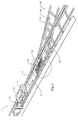
- Figure 1 is a diagrammatic perspective view of a part of the conveying system according to the invention.
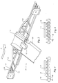
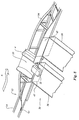
- Figure 2 is diagrammatic perspective view of a discharge station, where the contents of a trolley can be discharged from the trolley.
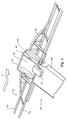
- Figure 3 shows a mechanism for driving the trolley near the discharge station.
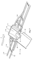
- Figure 4 shows another embodiment of a mechanism for driving the trolley near the discharge station.
- Figures 5-8 show variants of the embodiment according to figure 2.
- the conveying system shown in figure 1 comprises a first rail track 1, which comprises a pair of rails 2 and 3 extending parallel to each other.
- a trolley 4 is movable over said rails.
- the trolley 4 is thereby supported by running wheels provided at its bottom side, which roll over the upper surfaces of the rails 2 and 3.
- Linear motors 11, which are known per se, may be provided for driving the trolley 4.
- a conveying system of this type may for example be used at airports for conveying the luggage 12 of air passengers.
- additional rail tracks 13 are connected to the main rail track 1, generally at several points, via which a trolley may for example be guided to a predetermined station so as to deliver the luggage 12.
- Such an additional rail track 13 is again provided with a pair of rails 14 and 15 extending parallel to each other, which correspond with the rails 2 and 3.
- a switch device 16 is provided near the connection of the rail track 13 to the rail track 1 for diverting a trolley from the rail track 1 to the rail track 13.
- the switch device 16 as e.g. described in EP-A-0 659 624 is not part of the present invention and so it will not be necessary to give a detailled description of said switch device.
- a further switch means may be used for guiding the trolley back from rail track 13 to rail track 1.
- Rail track 13 may for example lead to a discharge station 33, as is diagrammatically illustrated in figure 2.
- a discharge station 33 as is diagrammatically illustrated in figure 2.
- an upwardly curved rail portion 34 is provided on the rail 14, so that during the movement of the trolley 4 over the rail track 7 said trolley 4 can be moved to such a position, that the surface 35 supporting the luggage will take such an inclined position that the luggage 12 will slide from the trolley under the influence of gravity, and will be received on for example a conveyor belt 36 or the like for the further discharge of the luggage.
- the construction may also be such that an elevated portion is provided on the rail 15, so that the luggage is delivered on the side of the rail track 13 opposite the side shown in figure 2.
- the curved rail portion 34 may be a downwardly curved rail portion.
- a bar-like means 37 extending parallel to the intended direction of movement is secured to the frame of the trolley 4, said bar-like means 37 near the discharge station 33 being guided by a plurality of spaced-apart guide rollers 38 or the like (figure 3) extending above said bar-like means.
- the upper part of a driven endless conveyor belt 39 extending parallel to said bar-like means engages on the bottom side of the bar-like means 37.
- supporting rollers 40 are provided under the upper part of the endless conveyor belt 39.
- an endless conveyor belt or chain may be used, to which supporting rollers are secured, which run over a guideway.
- Figure 4 shows a variant to the embodiment of figure 3, wherein the same reference numerals are used for those parts of figure 3 that correspond with the parts illustrated in figure 3.
- rollers 41 which can be driven during operation, are arranged one behind the other, said rollers engaging on the bottom side of the bar-like means 37, as will be apparent from figure 4.
- the rollers 41 may thereby be driven from a single driving source (not shown) because the rollers are interconnected by means of chains or belts 42, as is diagrammaticaly illustrated in figure 4.
- spring-loaded rollers 38 may or may not be used.
- Figures 5-8 show a few variants to the embodiment according to figure 2 and consequently like parts are numbered alike in the various figures.
- the space in the trolley 4 for accommodating the luggage 12 is open at the opposite sides, so that the luggage will slide from the trolley under the influence of gravity when at least the supporting surface 35 of the trolley is tilted.
- a flap 43 is provided near each end of supporting surface 35 for that purpose, said flap being pivotally coupled to the trolley by means of arms 44 and pivot pins 45 extending parallel to the intended direction of movement of the trolley.
- the flap 43 may thereby be pivoted, for example by guide means (not shown) provided along the rail track 13 or by setting means (not shown), between an upwardly pivoted position shown at the top of figure 5, in which the opening located near that end of the supporting surface 35 is closed, and a position shown near the bottom end of the trolley in figure 5, in which the opening of the cargo space of the trolley located near the conveyor belt 36 is released and the luggage can slide from the cargo space of the trolley 4 in the manner shown in figure 5.
- FIG. 6 shows a similar embodiment, wherein closing means or walls 46 capable of upward and downward movement are provided near opposite sides of the trolley, which closing means or walls can be moved upward and downward by guide means or setting means.
- FIG. 7 shows an embodiment wherein flaps 46' are provided near the ends of the supporting surface, said flaps being capable of pivoting movement about pivot pins located near their bottom ends, between a closed position and an open position, in which said flaps 46' extends over the conveyor belt 36.
- a slide or closing means 47 capable of upward and downward movement is provided near the end of a conveyor belt 36 or the like connecting to the rail track 13, which slide or closing means 47, as will be apparent form figure 8, may be moved to a first downward position, in which the opening of a trolley passing the respective station is released and the luggage or the like can thus slide from the trolley, and to a second position shown on the right in figure 8, in which the closing means 47 moved to its upward position will prevent material present on a passing trolley 4 from being discharged.
- a discharge station 32 may comprise one or more discharge conveyors 36.
Landscapes
- Engineering & Computer Science (AREA)
- Mechanical Engineering (AREA)
- Transportation (AREA)
- Architecture (AREA)
- Civil Engineering (AREA)
- Structural Engineering (AREA)
- Branching, Merging, And Special Transfer Between Conveyors (AREA)
- Intermediate Stations On Conveyors (AREA)
- Threshing Machine Elements (AREA)
- Control Of Conveyors (AREA)
- Railway Tracks (AREA)
- Platform Screen Doors And Railroad Systems (AREA)
- Non-Mechanical Conveyors (AREA)
- Control Of Vehicles With Linear Motors And Vehicles That Are Magnetically Levitated (AREA)
Applications Claiming Priority (3)
| Application Number | Priority Date | Filing Date | Title |
|---|---|---|---|
| NL9302211 | 1993-12-20 | ||
| NL9302211A NL9302211A (nl) | 1993-12-20 | 1993-12-20 | Transportinstallatie. |
| EP94203618A EP0659624B1 (de) | 1993-12-20 | 1994-12-14 | Ein Transportsystem |
Related Parent Applications (2)
| Application Number | Title | Priority Date | Filing Date |
|---|---|---|---|
| EP94203618A Division EP0659624B1 (de) | 1993-12-20 | 1994-12-14 | Ein Transportsystem |
| EP94203618.7 Division | 1994-12-14 |
Publications (2)
| Publication Number | Publication Date |
|---|---|
| EP0806384A2 true EP0806384A2 (de) | 1997-11-12 |
| EP0806384A3 EP0806384A3 (de) | 1998-01-07 |
Family
ID=19863282
Family Applications (2)
| Application Number | Title | Priority Date | Filing Date |
|---|---|---|---|
| EP97202370A Withdrawn EP0806384A3 (de) | 1993-12-20 | 1994-12-14 | Fördersystem |
| EP94203618A Expired - Lifetime EP0659624B1 (de) | 1993-12-20 | 1994-12-14 | Ein Transportsystem |
Family Applications After (1)
| Application Number | Title | Priority Date | Filing Date |
|---|---|---|---|
| EP94203618A Expired - Lifetime EP0659624B1 (de) | 1993-12-20 | 1994-12-14 | Ein Transportsystem |
Country Status (9)
| Country | Link |
|---|---|
| US (1) | US5590995A (de) |
| EP (2) | EP0806384A3 (de) |
| JP (1) | JPH0858575A (de) |
| CN (1) | CN1114629A (de) |
| AT (1) | ATE183157T1 (de) |
| CA (1) | CA2138315A1 (de) |
| DE (1) | DE69420021T2 (de) |
| DK (1) | DK0659624T3 (de) |
| NL (1) | NL9302211A (de) |
Cited By (7)
| Publication number | Priority date | Publication date | Assignee | Title |
|---|---|---|---|---|
| EP1388510A1 (de) | 2002-08-07 | 2004-02-11 | Siemens Aktiengesellschaft | Transportsystem für Stückgutbehälter, insbesondere für Gepäckbehälter |
| DE10315404A1 (de) * | 2003-02-27 | 2004-09-23 | Siemens Ag | Fördersystem für Behälter, insbesondere eine Flughafen-Gepäckförderanlage |
| EP1475322A1 (de) | 2003-05-09 | 2004-11-10 | Siemens Aktiengesellschaft | Fördersystem, insbesondere eine Flughafen-Gepäckförderanlage |
| US7025195B2 (en) | 2003-02-27 | 2006-04-11 | Siemens Aktiengesellschaft | Conveyor system for transport of containers |
| EP2230198A3 (de) * | 2009-03-20 | 2013-05-15 | Siemens Aktiengesellschaft | Behälterförderanlage zum Transportieren von Stückgütern, insbesondere von Gepäckstücken |
| CN104986161A (zh) * | 2015-07-19 | 2015-10-21 | 李伦伟 | 电石输送列车 |
| DE102018121083A1 (de) * | 2018-08-29 | 2020-03-05 | Deutsche Post Ag | Verfahren zum Entladen von Packstücken aus einem gekippten Behälter auf ein Förderband |
Families Citing this family (48)
| Publication number | Priority date | Publication date | Assignee | Title |
|---|---|---|---|---|
| NL1002039C2 (nl) * | 1996-01-08 | 1997-07-09 | Vanderlande Ind Nederland | Transportinrichting. |
| NL1003975C2 (nl) * | 1996-09-06 | 1998-03-09 | Vanderlande Ind Nederland | Inrichting voor het transporteren van voorwerpen. |
| NL1004699C2 (nl) * | 1996-12-05 | 1998-06-08 | Vanderlande Ind Nederland | Transportinrichting. |
| US5990437A (en) * | 1997-02-05 | 1999-11-23 | W & H Systems, Inc. | System for sorting articles |
| US6460681B1 (en) * | 1997-02-05 | 2002-10-08 | W & H Systems | System for sorting articles using a double carrying tray |
| US6011508A (en) * | 1997-10-31 | 2000-01-04 | Magnemotion, Inc. | Accurate position-sensing and communications for guideway operated vehicles |
| DE69827411T2 (de) | 1997-12-12 | 2005-11-10 | Fki Logistex A/S | Förderanlage und verfahren zu deren betrieb |
| NL1007820C2 (nl) | 1997-12-17 | 1999-06-21 | Vanderlande Ind Nederland | Transportinrichting. |
| US6101952A (en) * | 1997-12-24 | 2000-08-15 | Magnemotion, Inc. | Vehicle guidance and switching via magnetic forces |
| NL1009222C2 (nl) | 1998-05-20 | 1999-11-24 | Vanderlande Ind Nederland | Werkwijze en installatie voor het transporteren van goederen alsmede combinatie van een bak en van een door wielen ondersteund frame voor het transporteren van goederen. |
| NL1010036C2 (nl) * | 1998-09-09 | 2000-03-10 | Vanderlande Ind Nederland | Transportinrichting. |
| US6781524B1 (en) | 2000-03-17 | 2004-08-24 | Magnemotion, Inc. | Passive position-sensing and communications for vehicles on a pathway |
| AU2002247086A1 (en) * | 2001-02-09 | 2002-08-28 | Paragon Technologies, Inc. | Narrow belt conveyor system |
| US6619473B2 (en) | 2001-07-11 | 2003-09-16 | Rapistan Systems Advertising Corp. | Bolt-up conveyor |
| ATE394311T1 (de) | 2001-09-27 | 2008-05-15 | Fki Logistex As | Tragbehälter für förderer |
| US6917136B2 (en) * | 2001-10-01 | 2005-07-12 | Magnemotion, Inc. | Synchronous machine design and manufacturing |
| US6983701B2 (en) * | 2001-10-01 | 2006-01-10 | Magnemotion, Inc. | Suspending, guiding and propelling vehicles using magnetic forces |
| JP4310733B2 (ja) * | 2003-09-08 | 2009-08-12 | 株式会社ダイフク | 摩擦駆動の台車式搬送装置 |
| JP4310734B2 (ja) * | 2003-09-08 | 2009-08-12 | 株式会社ダイフク | 摩擦駆動の台車式搬送装置 |
| US7458454B2 (en) * | 2004-05-07 | 2008-12-02 | Magnemotion, Inc. | Three-dimensional motion using single-pathway based actuators |
| DE102004031444A1 (de) | 2004-06-29 | 2006-01-26 | Bosch Rexroth Aktiengesellschaft | Fördervorrichtung mit Weiche bei Übereinanderanordnung der Laufbahnen |
| DE102004031443A1 (de) | 2004-06-29 | 2006-01-26 | Bosch Rexroth Aktiengesellschaft | Fördervorrichtung mit einem Transportwagen mit achsfluchtenden Laufrollen |
| CN101489849A (zh) * | 2005-07-22 | 2009-07-22 | 麦克纳莫绅有限公司 | 车辆的导轨启动的磁性转辙 |
| CN100388455C (zh) * | 2005-09-29 | 2008-05-14 | 中芯国际集成电路制造(上海)有限公司 | 具有安全挡板的晶舟盒导轨传动装置 |
| JP5040271B2 (ja) * | 2006-11-17 | 2012-10-03 | 村田機械株式会社 | 有軌道搬送装置 |
| CZ2008467A3 (cs) * | 2008-07-31 | 2010-02-10 | Dt-Výhybkárna A Strojírna, A. S. | Bloková tramvajová kolejová pulvýmena |
| US8616134B2 (en) | 2009-01-23 | 2013-12-31 | Magnemotion, Inc. | Transport system powered by short block linear synchronous motors |
| US9032880B2 (en) | 2009-01-23 | 2015-05-19 | Magnemotion, Inc. | Transport system powered by short block linear synchronous motors and switching mechanism |
| JP5077399B2 (ja) * | 2010-07-30 | 2012-11-21 | トヨタ自動車株式会社 | 台車式搬送装置 |
| US9090415B2 (en) * | 2012-09-05 | 2015-07-28 | General Electric Company | System and method for rolling a vehicle to unload cargo |
| CN105813886B (zh) | 2013-09-21 | 2018-04-03 | 麦克纳莫绅有限公司 | 用于包装和其它用途的线性电机运输 |
| CN105080846B (zh) * | 2015-06-15 | 2018-01-02 | 河南科技大学 | 一种轨道装置及使用该轨道装置的物流分拣装置 |
| DE102015218396A1 (de) | 2015-09-24 | 2017-03-30 | Gebr. Willach Gmbh | Förderkette für eine Warenübergabevorrichtung eines automatischen Warenlagers |
| CN106672569A (zh) * | 2016-11-28 | 2017-05-17 | 哈工大机器人集团上海有限公司 | 一种送餐装置 |
| CN106429276A (zh) * | 2016-12-05 | 2017-02-22 | 无锡润和机电技术有限公司 | 筒式原纸用回转小车地轨系统 |
| WO2018203284A1 (en) | 2017-05-03 | 2018-11-08 | Dematic Corp. | Conveyor belt drive system and configuration |
| MX2020002736A (es) | 2017-09-13 | 2020-07-21 | Laitram Llc | Transportador de bandeja de monorriel con rieles de guia pasivos. |
| CN108163512A (zh) * | 2017-12-31 | 2018-06-15 | 嘉兴君屹工程有限公司 | 一种l型滑台 |
| CN108657810B (zh) * | 2018-07-03 | 2024-03-26 | 东莞市运泰自动化科技有限公司 | 一种产品与料盒分离机 |
| CN109399165B (zh) * | 2018-12-22 | 2024-03-19 | 湖南宏碧园食品有限公司 | 一种食品加工用的输送线转换系统 |
| CN109748055B (zh) * | 2019-03-14 | 2024-01-26 | 重庆大学 | 有向磁性轨道布置结构 |
| JP2022534713A (ja) * | 2019-05-28 | 2022-08-03 | ベーウントエル・インダストリアル・オートメイション・ゲゼルシャフト・ミト・ベシュレンクテル・ハフツング | 運搬装置 |
| CN110255158B (zh) * | 2019-07-03 | 2024-03-29 | 佛山市蓝箭电子股份有限公司 | 半导体封装粘片设备的翻转上料装置 |
| CN110641942A (zh) * | 2019-11-14 | 2020-01-03 | 民航成都物流技术有限公司 | 一种用于行李处理的高速小车轨道系统 |
| CN111252438A (zh) * | 2020-03-24 | 2020-06-09 | 杭州迅蚁网络科技有限公司 | 一种自动化仓储系统 |
| CN111891142B (zh) * | 2020-09-03 | 2024-06-25 | 山西中科智能控制技术研究院有限公司 | 一种磁牵引行走装置 |
| CN114985272B (zh) * | 2022-06-01 | 2023-07-07 | 港宏机械工程(南京)有限公司 | 一种物流智能分拣转向装置 |
| CN115339374B (zh) * | 2022-08-29 | 2023-12-15 | 中国电子科技集团公司第十四研究所 | 一种用于产线的自动送料和上料小车及自动送料和上料方法 |
Family Cites Families (31)
| Publication number | Priority date | Publication date | Assignee | Title |
|---|---|---|---|---|
| US282125A (en) * | 1883-07-31 | Car-unloading apparatus | ||
| BE547931A (de) * | ||||
| US1016570A (en) * | 1911-06-02 | 1912-02-06 | Charles L Lawton | Dump-car. |
| US1135669A (en) * | 1914-05-13 | 1915-04-13 | Hans Culemeyer | Device for unloading trucks or freight-cars by tilting them. |
| US1491060A (en) * | 1922-10-14 | 1924-04-22 | O'toole Edward | Car-dumping apparatus |
| US1716240A (en) * | 1925-09-25 | 1929-06-04 | Postweiler Charles | Apparatus for the unloading of railroad cars and other vehicles |
| US2290844A (en) * | 1940-04-20 | 1942-07-21 | Lionel Corp | Unloading toy vehicle and operating device for the same |
| DE1051895B (de) * | 1953-02-13 | 1959-03-05 | Jakob Huber Dr Ing | Einrichtung an Gleisanlagen fuer Schienenfahrzeuge |
| US3013499A (en) * | 1957-05-06 | 1961-12-19 | Cie Francaise De L Afrique Occ | Conveyer systems |
| GB1137099A (en) * | 1966-11-29 | 1968-12-18 | Sovex Ltd | Improvements relating to sorting conveyors |
| US3463298A (en) * | 1967-05-16 | 1969-08-26 | Spra Con Co The | Tray constructions for conveyors |
| US3752334A (en) * | 1971-11-18 | 1973-08-14 | Dravo Corp | Industrial bulk material transportation |
| US3768624A (en) * | 1972-02-11 | 1973-10-30 | Kornylac Co | Elastic belt conveyor |
| US3818839A (en) * | 1972-11-24 | 1974-06-25 | Rexnord Inc | Parallel wheel drive |
| US3880751A (en) * | 1973-12-27 | 1975-04-29 | Speaker Motion Systems | Conveyors with lateral discharge apparatus |
| US3977513A (en) * | 1974-05-28 | 1976-08-31 | Sun Chemical Corporation | Cart conveyor system |
| US3994405A (en) * | 1975-08-26 | 1976-11-30 | Rexnord Inc. | Constant clearance luggage container unloader |
| US4063656A (en) * | 1976-06-24 | 1977-12-20 | Rexnord Inc. | System and apparatus for moving and unloading articles |
| SU992371A1 (ru) * | 1980-06-10 | 1983-01-30 | за вители «С СОЮЗЙДЯ М «ATEffTHoТЕХШ№БС.4Я ««БЛйОЩд | Устройство дл разгрузки сыпучих грузов из бортовых автомобилей |
| US4415303A (en) * | 1981-05-14 | 1983-11-15 | Westendorf Manufacturing Company | Auger wagon |
| SU1133203A1 (ru) * | 1982-04-14 | 1985-01-07 | Dvoryanidov Aleksandr G | Автомобилеразгрузчик |
| AT393819B (de) * | 1983-03-29 | 1991-12-27 | Sticht Fertigungstech Stiwa | Foerdereinrichtung fuer werkstuecke bzw. werkstuecktraeger, insbesondere fuer eine montagemaschine |
| IT1183258B (it) * | 1983-12-02 | 1987-10-22 | Pinfari Srl | Impianto ferroviario a trazione elettrica |
| US4665832A (en) * | 1984-10-22 | 1987-05-19 | Mazda Motor Corporation | Vehicle transfer system |
| IT8520636U1 (it) * | 1985-01-29 | 1986-07-29 | Canziani Francesco | Carrello in particolare per smistatrici a piattelli ribaltabili |
| SE448083B (sv) * | 1985-05-29 | 1987-01-19 | Per Erik Wahren | Transportbana med paletter for transport av tyngre laster |
| JPS63277130A (ja) * | 1987-05-08 | 1988-11-15 | Daifuku Co Ltd | リニアモ−タ−駆動の仕分け用搬送装置 |
| DE3834583A1 (de) * | 1988-10-11 | 1990-04-12 | Rixen Wolfgang | Transportvorrichtung fuer werkstuecke |
| SU1636308A1 (ru) * | 1989-04-11 | 1991-03-23 | Центрально-Черноземный Филиал Всесоюзного Научно-Исследовательского Института Удобрений И Агропочвоведения Им.Д.Н.Прянишникова | Перегрузочно-накопительное устройство |
| DE4210925C2 (de) * | 1992-04-02 | 1994-11-24 | Heinz Nowak | Magnetfahrbahnanlage |
| US5445081A (en) * | 1994-04-13 | 1995-08-29 | Yantrak, Llc | Transit system employing a traction belt |
-
1993
- 1993-12-20 NL NL9302211A patent/NL9302211A/nl not_active Application Discontinuation
-
1994
- 1994-12-14 DK DK94203618T patent/DK0659624T3/da active
- 1994-12-14 DE DE69420021T patent/DE69420021T2/de not_active Expired - Fee Related
- 1994-12-14 EP EP97202370A patent/EP0806384A3/de not_active Withdrawn
- 1994-12-14 EP EP94203618A patent/EP0659624B1/de not_active Expired - Lifetime
- 1994-12-14 AT AT94203618T patent/ATE183157T1/de not_active IP Right Cessation
- 1994-12-16 CA CA002138315A patent/CA2138315A1/en not_active Abandoned
- 1994-12-19 US US08/358,944 patent/US5590995A/en not_active Expired - Fee Related
- 1994-12-19 JP JP6333760A patent/JPH0858575A/ja active Pending
- 1994-12-20 CN CN94120726A patent/CN1114629A/zh active Pending
Cited By (12)
| Publication number | Priority date | Publication date | Assignee | Title |
|---|---|---|---|---|
| EP1388510A1 (de) | 2002-08-07 | 2004-02-11 | Siemens Aktiengesellschaft | Transportsystem für Stückgutbehälter, insbesondere für Gepäckbehälter |
| DE10236168B3 (de) * | 2002-08-07 | 2004-03-25 | Siemens Ag | Transportsystem für Stückgutbehälter, insbesondere für Gepäckbehälter |
| US6860377B2 (en) | 2002-08-07 | 2005-03-01 | Siemens Aktiengesellschaft | Transport system for cargo containers, in particular for baggage containers |
| DE10315404A1 (de) * | 2003-02-27 | 2004-09-23 | Siemens Ag | Fördersystem für Behälter, insbesondere eine Flughafen-Gepäckförderanlage |
| DE10315404B4 (de) * | 2003-02-27 | 2005-09-01 | Siemens Ag | Fördersystem für Behälter, insbesondere eine Flughafen-Gepäckförderanlage |
| US7025195B2 (en) | 2003-02-27 | 2006-04-11 | Siemens Aktiengesellschaft | Conveyor system for transport of containers |
| EP1475322A1 (de) | 2003-05-09 | 2004-11-10 | Siemens Aktiengesellschaft | Fördersystem, insbesondere eine Flughafen-Gepäckförderanlage |
| DE10320963A1 (de) * | 2003-05-09 | 2004-12-16 | Siemens Ag | Fördersystem, inbesondere eine Flughafen-Gepäckförderanlage, und eine Entladeeinrichtung eines Fördersystems für Behälter zum Transportieren von Gütern, insbesondere von Gepäckstücken |
| EP2230198A3 (de) * | 2009-03-20 | 2013-05-15 | Siemens Aktiengesellschaft | Behälterförderanlage zum Transportieren von Stückgütern, insbesondere von Gepäckstücken |
| CN104986161A (zh) * | 2015-07-19 | 2015-10-21 | 李伦伟 | 电石输送列车 |
| DE102018121083A1 (de) * | 2018-08-29 | 2020-03-05 | Deutsche Post Ag | Verfahren zum Entladen von Packstücken aus einem gekippten Behälter auf ein Förderband |
| US11401120B2 (en) | 2018-08-29 | 2022-08-02 | Deutsche Post Ag | Method for unloading packages from a tipped container onto a conveyor belt |
Also Published As
| Publication number | Publication date |
|---|---|
| DE69420021T2 (de) | 2000-01-20 |
| EP0806384A3 (de) | 1998-01-07 |
| ATE183157T1 (de) | 1999-08-15 |
| DK0659624T3 (da) | 1999-12-06 |
| EP0659624A1 (de) | 1995-06-28 |
| NL9302211A (nl) | 1995-07-17 |
| JPH0858575A (ja) | 1996-03-05 |
| EP0659624B1 (de) | 1999-08-11 |
| CN1114629A (zh) | 1996-01-10 |
| US5590995A (en) | 1997-01-07 |
| CA2138315A1 (en) | 1995-06-21 |
| DE69420021D1 (de) | 1999-09-16 |
Similar Documents
| Publication | Publication Date | Title |
|---|---|---|
| EP0806384A2 (de) | Fördersystem | |
| EP0626325B1 (de) | Förderer | |
| US5509526A (en) | Dual level tilting tray package sorting apparatus | |
| CA1224738A (en) | Plant for sorting items, with self driven carriages | |
| US5535874A (en) | Carrier for transport and delivery of an article to a destination | |
| CA2278283C (en) | Detachable material handling tray with automatic parcel ejection mechanism | |
| US20050133345A1 (en) | Positive displacement sorter | |
| US6607066B1 (en) | Conveyor | |
| CA1069847A (en) | Cart conveyor system | |
| US4957188A (en) | Conveyor system with stabilized conveyor basket | |
| EP0784026B1 (de) | Förderer | |
| EP0425021B1 (de) | Fördervorrichtung | |
| US4010824A (en) | Conveyor system for drive-in banks and the like | |
| JP2002505244A (ja) | 生産物の寸法分類輸送機構 | |
| EP3696122B1 (de) | Querbandsortierer | |
| CN116867720B (zh) | 分拣装置 | |
| US20070221477A1 (en) | Method and Device for Buffering Products |
Legal Events
| Date | Code | Title | Description |
|---|---|---|---|
| PUAI | Public reference made under article 153(3) epc to a published international application that has entered the european phase |
Free format text: ORIGINAL CODE: 0009012 |
|
| AC | Divisional application: reference to earlier application |
Ref document number: 659624 Country of ref document: EP |
|
| AK | Designated contracting states |
Kind code of ref document: A2 Designated state(s): AT BE CH DE DK ES FR GB GR IE IT LI LU MC NL PT SE |
|
| AX | Request for extension of the european patent |
Free format text: LT PAYMENT 970731;SI PAYMENT 970731 |
|
| PUAL | Search report despatched |
Free format text: ORIGINAL CODE: 0009013 |
|
| AK | Designated contracting states |
Kind code of ref document: A3 Designated state(s): AT BE CH DE DK ES FR GB GR IE IT LI LU MC NL PT SE |
|
| AX | Request for extension of the european patent |
Free format text: LT PAYMENT 970731;SI PAYMENT 970731 |
|
| STAA | Information on the status of an ep patent application or granted ep patent |
Free format text: STATUS: THE APPLICATION IS DEEMED TO BE WITHDRAWN |
|
| 18D | Application deemed to be withdrawn |
Effective date: 19980708 |