EP0806380B1 - Procédé et dispositif pour orienter des produits - Google Patents
Procédé et dispositif pour orienter des produits Download PDFInfo
- Publication number
- EP0806380B1 EP0806380B1 EP97107560A EP97107560A EP0806380B1 EP 0806380 B1 EP0806380 B1 EP 0806380B1 EP 97107560 A EP97107560 A EP 97107560A EP 97107560 A EP97107560 A EP 97107560A EP 0806380 B1 EP0806380 B1 EP 0806380B1
- Authority
- EP
- European Patent Office
- Prior art keywords
- products
- product
- station
- transfer
- unit
- Prior art date
- Legal status (The legal status is an assumption and is not a legal conclusion. Google has not performed a legal analysis and makes no representation as to the accuracy of the status listed.)
- Expired - Lifetime
Links
- 238000000034 method Methods 0.000 title claims description 12
- 238000012546 transfer Methods 0.000 claims description 31
- 238000011144 upstream manufacturing Methods 0.000 claims description 8
- 230000002093 peripheral effect Effects 0.000 description 5
- 238000012545 processing Methods 0.000 description 4
- 238000012856 packing Methods 0.000 description 3
- 235000013305 food Nutrition 0.000 description 2
- 244000299461 Theobroma cacao Species 0.000 description 1
- 235000019219 chocolate Nutrition 0.000 description 1
- 235000009508 confectionery Nutrition 0.000 description 1
- 238000013461 design Methods 0.000 description 1
- 238000004806 packaging method and process Methods 0.000 description 1
- 230000009897 systematic effect Effects 0.000 description 1
Images

Classifications
-
- B—PERFORMING OPERATIONS; TRANSPORTING
- B65—CONVEYING; PACKING; STORING; HANDLING THIN OR FILAMENTARY MATERIAL
- B65G—TRANSPORT OR STORAGE DEVICES, e.g. CONVEYORS FOR LOADING OR TIPPING, SHOP CONVEYOR SYSTEMS OR PNEUMATIC TUBE CONVEYORS
- B65G47/00—Article or material-handling devices associated with conveyors; Methods employing such devices
- B65G47/22—Devices influencing the relative position or the attitude of articles during transit by conveyors
- B65G47/26—Devices influencing the relative position or the attitude of articles during transit by conveyors arranging the articles, e.g. varying spacing between individual articles
- B65G47/28—Devices influencing the relative position or the attitude of articles during transit by conveyors arranging the articles, e.g. varying spacing between individual articles during transit by a single conveyor
- B65G47/29—Devices influencing the relative position or the attitude of articles during transit by conveyors arranging the articles, e.g. varying spacing between individual articles during transit by a single conveyor by temporarily stopping movement
-
- B—PERFORMING OPERATIONS; TRANSPORTING
- B65—CONVEYING; PACKING; STORING; HANDLING THIN OR FILAMENTARY MATERIAL
- B65G—TRANSPORT OR STORAGE DEVICES, e.g. CONVEYORS FOR LOADING OR TIPPING, SHOP CONVEYOR SYSTEMS OR PNEUMATIC TUBE CONVEYORS
- B65G47/00—Article or material-handling devices associated with conveyors; Methods employing such devices
- B65G47/02—Devices for feeding articles or materials to conveyors
- B65G47/04—Devices for feeding articles or materials to conveyors for feeding articles
- B65G47/06—Devices for feeding articles or materials to conveyors for feeding articles from a single group of articles arranged in orderly pattern, e.g. workpieces in magazines
- B65G47/08—Devices for feeding articles or materials to conveyors for feeding articles from a single group of articles arranged in orderly pattern, e.g. workpieces in magazines spacing or grouping the articles during feeding
- B65G47/082—Devices for feeding articles or materials to conveyors for feeding articles from a single group of articles arranged in orderly pattern, e.g. workpieces in magazines spacing or grouping the articles during feeding grouping articles in rows
-
- B—PERFORMING OPERATIONS; TRANSPORTING
- B65—CONVEYING; PACKING; STORING; HANDLING THIN OR FILAMENTARY MATERIAL
- B65G—TRANSPORT OR STORAGE DEVICES, e.g. CONVEYORS FOR LOADING OR TIPPING, SHOP CONVEYOR SYSTEMS OR PNEUMATIC TUBE CONVEYORS
- B65G47/00—Article or material-handling devices associated with conveyors; Methods employing such devices
- B65G47/22—Devices influencing the relative position or the attitude of articles during transit by conveyors
- B65G47/26—Devices influencing the relative position or the attitude of articles during transit by conveyors arranging the articles, e.g. varying spacing between individual articles
- B65G47/30—Devices influencing the relative position or the attitude of articles during transit by conveyors arranging the articles, e.g. varying spacing between individual articles during transit by a series of conveyors
- B65G47/31—Devices influencing the relative position or the attitude of articles during transit by conveyors arranging the articles, e.g. varying spacing between individual articles during transit by a series of conveyors by varying the relative speeds of the conveyors forming the series
Definitions
- the present invention relates to a method of ordering products.
- the present invention relates to a method of ordering products as they are fed onto a machine.
- the present invention is particularly advantageous for use in the food packing industry, for packing products such as chocolates or similar, to which the following description refers purely by way of example.
- products are supplied to a machine featuring an input conveying device having a number of conveying elements, which are fed at a given rate and with a given timing through a loading station where each receives a respective product.
- the products are normally supplied in an orderly manner to the conveying device by means of a supply line, of which the conveying device forms the end element.
- Known supply lines normally comprise an ordering device for feeding a succession of products in a given traveling direction at said frequency, and for gradually bringing the products into contact with one another to form a continuous column of products for supply to a pickup station; and a transfer device extending between the pickup and loading stations, and which feeds the products to the loading station in time with said conveying elements.
- the ordering device of known supply lines of the above type is normally defined by a conveyor belt
- the transfer device is normally defined by a wheel mounted for rotation about an axis crosswise to the traveling direction, and having a succession of equally spaced peripheral suction seats alternating with respective peripheral blow openings, and which are fed through the pickup and loading stations in time with the conveying elements.
- Each suction seat provides for engaging and removing the first product in the column from the pickup station in time with a respective conveying element, while the peripheral blow openings suspend removal of the products from the pickup station and temporarily arrest the whole column if the first product in the column is already located at the pickup station.
- temporary stoppage of the column is not accompanied by a corresponding stoppage of the conveyor belt, this slides beneath and gradually damages the products.
- more recent transfer devices feature, in place of the suction seats, a number of orientable heads, each having a respective gripping element, and each orientable in relation to the traveling direction of the products by means of a control unit controlled by a photocell located at one end of the conveyor belt to detect transit of the products.
- the control unit On receiving a product transit signal, calculates the difference between the position of the product and the position of the respective gripping element in relation to the pickup station, and so orients the head as to advance or delay passage of the gripping element through the pickup station.
- EP0608861 discloses an apparatus for feeding sensitive objects to a processing machine.
- a processing machine in particular a packaging machine
- a feeding conveyor which feeds the objects to the processing machine and onto which the objects are loaded using a driver conveyor
- the drivers of the driver conveyor engaging in such a manner between the previously scattered objects that by controlling the conveying speed of the objects and the rotational speed of the driver conveyor the objects are brought to rest against the drivers of the driver conveyor and, as a result, the objects are transferred to the adjacent feeding conveyors with high positional precision even at high operating speeds.
- EP0608861 discloses a method of ordering products as the products are supplied, in a given direction and along a given path, to a conveying device having a number of conveying elements movable through a loading station at a given frequency and with a given timing to each receive a respective product; the method comprising the steps of feeding the products successively at the frequency and with any timing up to a transfer station located upstream from the loading station in the direction, and transferring the products from the transfer station to the loading station at the frequency to feed the products to the loading station in time with respective conveying elements.
- the transfer step comprises the substeps of feeding each product into a respective supply pocket, the pocket having a given stop portion, and a dimension, measured in the direction, greater than a dimension of the products measured in the same direction; moving each product inside the respective pocket by means of mechanic brake means to position the product precisely at the respective stop portion; and feeding each stop portion through the loading station in time with the relative conveying element.
- the aforementioned unit tends to damages the products when the products are move inside the relevant pockets, in particular in combination with high processing speed.
- the present invention also relates to a unit for feeding products in an orderly manner to a machine.
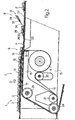
- Number 1 in Figure 1 indicates a unit for ordering products 2 and for feeding products 2 to a conveying device 3 in a direction D and along a given path P.
- Conveying device 3 comprises a number of known gripping or loading heads 4 equally spaced about a vertical axis of rotation 5 of conveying device 3, and which are fed at a given frequency F and with a given timing J through a loading station 6.
- Unit 1 comprises a supply device 7 and a transfer device 8 in series with each other along path P, and which cooperate with each other to feed products 2 along path P at frequency F to conveying device 3. More specifically, transfer device 8 receives products 2 from supply device 7 at a transfer station 9 located upstream from station 6 in direction D, and feeds each product 2 to station 6 in time with a respective gripping head 4.
- Device 7 receives products 2 from a known ordering device (not shown) for arranging products 2 substantially contacting one another, and feeds products 2 successively with any timing up to station 9.
- Supply device 7 comprises a conveyor belt 10 narrower than products 2 so that the lateral end portions of products 2 project outwards of belt 10, and which is looped about a powered pulley 11 and an idle pulley 12, which are fitted in rotary manner to a frame 13 and define, on belt 10, a transportation branch 14 extending along path P up to station 9.
- Device 7 also comprises a plate 15 extending beneath branch 14 between pulleys 11 and 12, and having a shaped upper profile 16 substantially contacting branch 14. More specifically, and as shown clearly in Figure 2, profile 16 comprises an initial horizontal portion 17 aligned with a peripheral tangent of pulley 12; and a vertical end portion 18 aligned with a peripheral tangent of pulley 11 and connected to portion 17 by an inclined portion 19 located at station 9 so that transportation branch 14 slopes downwards in direction D. Finally, device 7 comprises a pair of takeup pulleys 20 and 21, the first of which is located outwards of belt 10, between pulleys 21 and 11 and close to pulley 11, and is fitted to frame 13 by means of a known elastic support (not shown).
- Transfer device 8 comprises a pair of identical conveyor belts 22 (only one shown) located on either side of belt 10 and looped about four pairs of pulleys 23, 24, 25, 26 fitted in rotary manner to frame 13; pulleys 23 are integral with each other and define a single drive pulley for driving belts 22; pulleys 24 are located substantially at pulley 21, beneath transportation branch 14; pulleys 25 are located beneath portion 17 of plate 15, upstream from station 9 in direction D; and pulleys 26 are located at station 6, and define, on belts 22 and together with pulleys 25, respective horizontal transportation branches 27 extending along path P from station 9 to station 6, and lower than both branch 14 and gripping heads 4 of conveying device 3, so that: at station 9, branches 27 are located directly alongside a bottom end of inclined portion 19 of plate 15; and, at station 6, heads 4, in use, travel facing branches 27, and are located over branches 27 at a height substantially equal to a thickness of products 2.
- Belts 22 comprise a number of supply pockets 28, each of which receives a respective product 2 at station 9 in such a manner that said lateral end portions of product 2 contact belts 22, and each of which comprises a dimension, measured in direction D, greater than a dimension of product 2 also measured in direction D. More specifically, each pocket 28 receives a respective product 2 with a variable amount of slack in direction D, and comprises a stop portion 29, which is fed through station 6 at frequency F and with timing J, hence in time with heads 4, and is defined by two projections 30 (only one shown) extending outwards from respective belts 22 and of a thickness less than the difference in the level of transportation branches 14 and 27 of belts 10 and 22 at station 9.
- device 8 comprises brake means in the form of a positioning device 31 located over branch 27, upstream from station 6 in direction D, and for braking each product 2 to move the product 2 inside respective pocket 28 and into a position adjacent to projections 30, so that product 2 is supplied to station 6 in perfect time with relative gripping head 4.
- brake means 31 are pneumatic, and comprise a push element 32 defined by a nozzle 33 pointing in the opposite direction to the traveling direction of products 2, and connected to a known pneumatic device (not shown) to direct a jet 34 of air onto products 2 and move the products 2 inside respective pockets 28 into a position adjacent to and contacting projections 30.
- the frequency F at which products 2 are fed along path P is imposed at all times by conveying device 3, which feeds heads 4 through station 6 at frequency F and at a given speed V having a component, in direction D, at least equal to a traveling speed V1 of pockets 28 along path P.
- transfer device 8 feeds pockets 28 through stations 9 and 6 at frequency F, so that each head 4 always receives a product 2 from respective pocket 28 at station 6, while supply device 7 feeds products 2 to station 9 at frequency F, so that each pocket 28 always receives a product 2.
- the operating frequency of unit 1 is adjusted according to any change in frequency F of conveying device 3 by means of a known control unit (not shown) commonly used for this purpose and connected to the drives of devices 3, 7 and 8.
- supply device 7 feeds products 2 successively and substantially continuously to station 9 at a speed V2 lower than speed V1, and feeds them to transfer device 8 at station 9 by transferring them from branch 14 directly into respective pockets 28. That is, since transportation branches 14 and 27 of respective belts 10 and 22 are located at different levels, and since branch 14 is guided by plate 15 - in particular, by inclined portion 19 of plate 15 - so as to be inserted between branches 27, device 7 feeds products 2 directly into pockets 28, at any point along pockets 28 with respect to respective projections 30.
- each product 2 is deposited gradually inside respective pocket 28. That is, inclined portion 19, which is of a length equal to said dimension of product 2 measured in direction D, ensures product 2 contacts belts 22 before projections 30 reach station 9. As such, on contacting belts 22, product 2 is not only accelerated from speed V2 to speed V1, but is also distanced from the following product 2 to enable relative projections 30 to be positioned between the two products 2. The distance, measured in direction D, between two adjacent products 2 on branches 27 inside pockets 28 is therefore greater than the distance, measured in direction D, between two products 2 on branch 14.
- transfer device 8 feeds products 2 to station 6, where heads 4 of conveying device 3 receive products 2 and transfer them from station 6 to the input of a machine (not shown), e.g. a wrapping machine.
- a machine e.g. a wrapping machine.
- unit 1 provides for timing products 2 with respect to heads 4 in a straightforward and particularly effective manner with no need for sophisticated control systems.
- push element 32 of brake means 31 is replaced by a pneumatic plate located upstream from station 6 in direction D, between branches 27, and having a number of holes connected to a pneumatic device for forming an air cushion over the plate to detach products 2 slightly from belts 22.
- the loss in speed of products 2 with respect to belts 22 during detachment moves products 2 gradually inside respective pockets 28 to position products 2 against respective projections 30.
- pneumatic brake means 31 are replaced by friction brake means, and push element 32 is replaced by a straightforward fixed plate located upstream from station 6 in direction D and along path P between branches 27.
- the upper surface of the fixed plate is located at a slightly higher level than branches 27, so as to detach products 2 from belts 22 at that point along path P, cause a loss in speed of products 2 as they slide along the upper surface, and so position products 2 correctly against respective projections 30.
Landscapes
- Engineering & Computer Science (AREA)
- Mechanical Engineering (AREA)
- Specific Conveyance Elements (AREA)
- Organic Low-Molecular-Weight Compounds And Preparation Thereof (AREA)
- Attitude Control For Articles On Conveyors (AREA)
Claims (10)
- Méthode de rangement de produits dans laquelle les produits sont convoyés selon une direction donnée (D) et le long d'une voie d'accès donnée (P), par un dispositif transporteur (3) ayant un nombre d'éléments transporteurs (4), déplaçables à travers une station de chargement (6) à une fréquence donnée (F) et à des moments donnés (J) pour recevoir chacun un produit respectif (2), la méthode comportant les étapes consistant à amener successivement les produits (2) à la fréquence (F) et aux moments donnés jusqu'à la station de transfert (9) située en amont de la station de chargement (6) selon la direction susmentionnée (D); et à transférer les produits de la station de transfert (9) à la station de chargement(6) à la fréquence (F) pour amener les produits à la station de chargement (6) en même temps que les éléments transporteurs respectifs (4), où l'étape de transfert comporte des sous-étapes pour amener chaque produit (2) dans une poche d'approvisionnement respective (28); cette poche ayant une butée d'arrêt (29) et une dimension, déterminée selon la direction (D), plus grande que la dimension d'un produit (2) mesurée selon la même direction (D), à déplacer chaque produit (2) à l'intérieur de la poche respective (28) afin de positionner le produit avec précision sur la butée d'arrêt respective (29), et à alimenter chaque butée d'arrêt (29) par la station de chargement (6) en temps avec l'élément transporteur (4), la méthode étant caractérisée en ce que l'étape de déplacement est exécutée en freinant chaque produit (2) par l'intermédiaire de moyens pneumatiques de freinage (31) situés entre les stations de transfert et les stations de chargement (9,6) et en émettant un jet d'air (34) pour déplacer chaque produit (2) par rapport à la poche (28) respective.
- Méthode selon la revendication 1, dans laquelle les moyens de freinage (31) comprennent une buse (33) pour émettre le jet d'air (34), la buse (33) étant orientée selon une direction opposée à la direction(D) des produits (2).
- Méthode selon la revendication 1 ou 2, dans laquelle l'étape de transfert comprend une sous-étape d'accélération de chaque produit (2) pendant que le produit (2) est introduit dans la poche (28) respective.
- Unité (1) pour le rangement de produits (2), l'unité (1) comportant des moyens d'approvisionnement (7.8) pour l'amenée des produits (2), selon une direction donnée (D) et le long d'un chemin donné (P), vers un dispositif de transport (3) ayant un certain nombre d'éléments transporteur (4) déplaçables à travers la station de chargement (6) à une fréquence donnée (F) et à des moments donnés (J) pour recevoir chacun un produit respectif (2); des moyens transporteurs (7) pour l'amenée successive des produits (2) à la fréquence (F) et aux moments donnés vers la station de transfert (9) située en amont de la station de chargement (6) selon la direction (D); et des moyens de transfert (8) pour transférer les produits(2) de la station de transfert (9) à la station de chargement (6) à la fréquence (F), pour amener les produits (2) à la station de chargement (6) en même temps que les éléments transporteurs respectifs (4); les moyens de transfert (8) comprenant au moins une poche d'approvisionnement (28) pour recevoir un produit respectif (2) à la station de transfert (9), la poche (28) présentant une butée d'arrêt (29) et une dimension, déterminée selon la direction(D), plus grande que la dimension du produit (2) selon la même direction (D); et des moyens de freinage (31) pour déplacer chaque produit (2) à l'intérieur de la poche respective(28) afin de positionner avec précision le produit (2) sur la butée d'arrêt respective (29); chaque butée d'arrêt (29) étant alimentée en fonctionnement par la station de chargement(6) en temps avec l'élément transporteur (4); l'unité (1) étant caractérisée en ce les moyens de freinage(31) sont situés entre les station de transfert et de chargement (9,6) pour freiner et déplacer chaque produit (2) à l'intérieur de sa poche respective(28) et qu'il y a des moyens de freinage pneumatique (31) qui émettent un jet d'air (34) pour déplacer chaque produit(2) en relation avec sa poche respective(28).
- Unité selon la revendication 4, dans laquelle les moyens de freinage (31) comprennent une buse (3) qui émet un jet d'air (34), la buse (33) étant orientée selon la direction opposée à la direction (D) du produit (2).
- Unité selon la revendication 4 ou 5, dans laquelle les moyens transporteurs (7) comprennent une courroie transporteuse (10) présentant une branche transporteuse (14) s'étendant le long du chemin (P) jusqu'à lad station de transfert (9); les moyens de transfert (8) comprenant deux autres courroies transporteuses (22) situées de chaque côté de la courroie (10) au moins à la station de transfert (9).
- Unité selon la revendication 6, dans laquelle les autres courroies transporteuses (22) comprennent des autres branches transporteuses (27) respectives s'étendant à travers la station de transfert (9) et la station de chargement (6) ; la branche transporteuse (14) étant située à un niveau plus haut que les autres branches transporteuses (27) et étant insérée entre les autres branches transporteuses (27) de la station transporteuse (9).
- Unité selon la revendication 7, dans laquelle la branche transporteuse (14) comprend une partie inclinée (19) à la station de transfert (9).
- Unité selon la revendication 8, dans laquelle la partie inclinée (19) descend vers le bas selon cette direction (D).
- Unité selon l'une quelconque des revendications 6 à 8, dans laquelle la butée d'arrêt est définie par une saillie (30) pour chacune des autres courroies transporteuses.
Applications Claiming Priority (2)
| Application Number | Priority Date | Filing Date | Title |
|---|---|---|---|
| IT96BO000254A IT1285692B1 (it) | 1996-05-08 | 1996-05-08 | Metodo ed unita' per l'ordinamento di prodotti |
| ITBO960254 | 1996-05-08 |
Publications (2)
| Publication Number | Publication Date |
|---|---|
| EP0806380A1 EP0806380A1 (fr) | 1997-11-12 |
| EP0806380B1 true EP0806380B1 (fr) | 2003-04-16 |
Family
ID=11341390
Family Applications (1)
| Application Number | Title | Priority Date | Filing Date |
|---|---|---|---|
| EP97107560A Expired - Lifetime EP0806380B1 (fr) | 1996-05-08 | 1997-05-07 | Procédé et dispositif pour orienter des produits |
Country Status (4)
| Country | Link |
|---|---|
| US (1) | US5915523A (fr) |
| EP (1) | EP0806380B1 (fr) |
| DE (1) | DE69720845T2 (fr) |
| IT (1) | IT1285692B1 (fr) |
Families Citing this family (13)
| Publication number | Priority date | Publication date | Assignee | Title |
|---|---|---|---|---|
| NL1006370C2 (nl) * | 1997-06-20 | 1998-12-22 | Kloeckner Haensel Tevopharm | Transportinrichting voor het versnellen van een reeks producten. |
| US6053359A (en) * | 1997-12-22 | 2000-04-25 | Mcdonald's Corporation | Automated beverage system |
| SE517272C2 (sv) * | 1999-10-12 | 2002-05-21 | Flexlink Components Ab | Anordning och förfarande för styrning av enheter i ett flöde |
| US6511062B1 (en) | 2000-02-07 | 2003-01-28 | Lockheed Martin Corporation | Presentation control for flat article singulation mechanism and sensors suitable for use therewith |
| US6662929B1 (en) * | 2000-11-17 | 2003-12-16 | Lockhead Martin Corporation | Parcel singulation software control logic |
| US6711462B2 (en) * | 2002-03-05 | 2004-03-23 | Lockheed Martin Corporation | System and method for collating items |
| FR2859714B1 (fr) * | 2003-09-12 | 2005-11-11 | Aries Packaging | Procede de formation et d'espacement de lots successifs d'articles |
| EP1626004A1 (fr) * | 2004-07-15 | 2006-02-15 | CAVANNA S.p.A. | Dispositif et procédé pour former des groupes de produits dans des systèmes de convoyage, particulièrement pour machines automatiques d'emballage |
| US20080135381A1 (en) * | 2004-10-22 | 2008-06-12 | Fps Food Processing Systems B. V. | Positioning Conveyor |
| DE102007005550A1 (de) * | 2007-01-25 | 2008-07-31 | Manfred Haiss | Einrichtung zum Umsetzen von Stückgütern |
| DE102009011302A1 (de) * | 2009-03-02 | 2010-09-09 | Kuka Roboter Gmbh | Vereinzeln von Gebindelagen |
| DE102014106235A1 (de) * | 2014-05-05 | 2015-11-05 | Wood-Flame Gmbh | Verfahren und Vorrichtung zur Qualitätskontrolle von stetig gefördertem Stückgut |
| DE112016001284B4 (de) | 2015-03-19 | 2022-06-23 | Gdm S.P.A. | Gruppierungseinheit und Verfahren zum Bilden von Gruppen von absorbierenden Hygieneartikeln in einer Verpackungsmaschine |
Family Cites Families (20)
| Publication number | Priority date | Publication date | Assignee | Title |
|---|---|---|---|---|
| US1299198A (en) * | 1918-11-26 | 1919-04-01 | David Low | Feeder especially adapted for asparagus-handling machines. |
| US2580086A (en) * | 1950-02-21 | 1951-12-25 | Fried Steel Equipment Mfg Corp | Strip conveyer |
| US3348655A (en) * | 1966-12-06 | 1967-10-24 | Kliklok Corp | Device for disentangling and conveying flanged receptacles |
| US3523603A (en) * | 1967-08-11 | 1970-08-11 | Bangor Punta Operations Inc | Conveyor table |
| US3667622A (en) * | 1970-08-17 | 1972-06-06 | Keller & Co C | Method of and means for stacking moulded articles in groups |
| US3721330A (en) * | 1971-02-08 | 1973-03-20 | Fmc Corp | Article timing and feeding mechanism |
| IT967479B (it) * | 1972-09-15 | 1974-02-28 | Cavanna M | Dispositivo di regolazione dell ali mentazione di prodotti ad una macchina confezionatrice |
| IT970180B (it) * | 1972-11-02 | 1974-04-10 | Cavanna M | Dispositivo per l abbinamento di prodotti e relativi imbalaggi durante l alimentazione di una macchina confezionatrice |
| FI48569C (fi) * | 1973-06-06 | 1974-11-11 | Rysti & Co Ab | Sahatun puutavaran annostelumenetelmä ja -laite. |
| US3901375A (en) * | 1974-02-04 | 1975-08-26 | Fmc Corp | Package feeding and timing mechanism |
| US3971481A (en) * | 1975-04-21 | 1976-07-27 | Roberto Gonzalez Barrera | Materials handling apparatus |
| US4077524A (en) * | 1976-05-19 | 1978-03-07 | Alpo Rysti | Apparatus for sequentially forwarding bodies to a conveyer |
| US4124113A (en) * | 1977-06-09 | 1978-11-07 | The Lodge & Shipley Company | Case indexer |
| DE3662592D1 (en) * | 1985-06-26 | 1989-05-03 | Sig Schweiz Industrieges | Apparatus for separating articles being in contact with each other |
| DE3604806A1 (de) * | 1986-02-15 | 1987-08-20 | Helmut Staufner | Vorrichtung zum registrieren bzw. erfassen vereinzelter gegenstaende |
| IT1248245B (it) * | 1991-06-21 | 1995-01-05 | Gd Spa | Dispositivo per l'avanzamento a passo costante di prodotti ricevuti alla rinfusa. |
| CH686363A5 (de) * | 1992-03-16 | 1996-03-15 | Martin Lehmann | Foerderanlage. |
| NL9200946A (nl) * | 1992-05-27 | 1993-12-16 | Mafo Howden B V | Wasinrichting. |
| DE4302575A1 (de) * | 1993-01-29 | 1994-08-04 | Pactec Dresden Gmbh | Einrichtung zum Zuführen kleiner empfindlicher Stückgüter |
| IT1273840B (it) * | 1994-11-11 | 1997-07-11 | Azionaria Costruzioni Acma Spa | Metodo e linea per l'alimentazione a passo di prodotti |
-
1996
- 1996-05-08 IT IT96BO000254A patent/IT1285692B1/it active IP Right Grant
-
1997
- 1997-05-07 EP EP97107560A patent/EP0806380B1/fr not_active Expired - Lifetime
- 1997-05-07 DE DE69720845T patent/DE69720845T2/de not_active Expired - Lifetime
- 1997-05-07 US US08/852,393 patent/US5915523A/en not_active Expired - Fee Related
Also Published As
| Publication number | Publication date |
|---|---|
| ITBO960254A0 (it) | 1996-05-08 |
| US5915523A (en) | 1999-06-29 |
| IT1285692B1 (it) | 1998-06-18 |
| DE69720845D1 (de) | 2003-05-22 |
| EP0806380A1 (fr) | 1997-11-12 |
| DE69720845T2 (de) | 2003-12-18 |
| ITBO960254A1 (it) | 1997-11-08 |
Similar Documents
| Publication | Publication Date | Title |
|---|---|---|
| EP0806380B1 (fr) | Procédé et dispositif pour orienter des produits | |
| US6889485B2 (en) | Article grouping mechanism | |
| US5310041A (en) | Device for equally-spaced transportation of randomly arranged incoming products | |
| US5762175A (en) | Apparatus for the ordered transportation of packs | |
| EP0711719B1 (fr) | Méthode pour transférer à distances égales des produits et ligne de transport à cet effet | |
| EP0994025B1 (fr) | Procédé et unité pour former un groupe d'objets dans une machine d'encartonnage | |
| EP1300351B1 (fr) | Procédé et dispositif pour l'alimentation ordonnée de produits reçus en désordre | |
| WO2012064277A1 (fr) | Dispositif de transfert | |
| EP1270459B1 (fr) | Unité pour l'alimentation continue de séquences ordonneés de produits à une station de déchargement | |
| US5287954A (en) | Device for equally-spaced in-line transportation of randomly arranged incoming products | |
| EP0413997B1 (fr) | Dispositif pour l'alimentation de produits d'une unité d'approvisionnement vers une unité de réception | |
| US9067736B2 (en) | Variable pitch system, apparatus and method | |
| KR100630541B1 (ko) | 이송장치 | |
| EP1447357B1 (fr) | Dispositif d'arrangement d'articles rigides | |
| JP6495204B2 (ja) | 搬送装置 | |
| JPH11513648A (ja) | 缶蓋の供給装置 | |
| EP1365979B1 (fr) | Mecanisme de groupage d'articles | |
| EP0846078B1 (fr) | Transporteur, et assembleuse a transporteur incorpore | |
| KR20040051563A (ko) | 분배 공급 장치 및 분배 공급 방법 | |
| JPH10194416A (ja) | 搬送コンベアにおける搬送物の停止装置及び該搬送物の方向転換装置 | |
| WO2000002801A2 (fr) | Dispositif permettant d'espacer a un intervalle predefini des recipients generalement en plastique, comprenant un element de separation et de freinage des recipients | |
| JPH0569940A (ja) | 物品蓄積装置 | |
| HK1028973B (en) | Transfer mechanism | |
| JPH0683631U (ja) | 仕分装置 |
Legal Events
| Date | Code | Title | Description |
|---|---|---|---|
| PUAI | Public reference made under article 153(3) epc to a published international application that has entered the european phase |
Free format text: ORIGINAL CODE: 0009012 |
|
| AK | Designated contracting states |
Kind code of ref document: A1 Designated state(s): CH DE GB IT LI NL |
|
| 17P | Request for examination filed |
Effective date: 19980502 |
|
| 17Q | First examination report despatched |
Effective date: 20020125 |
|
| GRAH | Despatch of communication of intention to grant a patent |
Free format text: ORIGINAL CODE: EPIDOS IGRA |
|
| GRAH | Despatch of communication of intention to grant a patent |
Free format text: ORIGINAL CODE: EPIDOS IGRA |
|
| GRAA | (expected) grant |
Free format text: ORIGINAL CODE: 0009210 |
|
| AK | Designated contracting states |
Designated state(s): CH DE GB IT LI NL |
|
| REG | Reference to a national code |
Ref country code: GB Ref legal event code: FG4D |
|
| REG | Reference to a national code |
Ref country code: CH Ref legal event code: EP |
|
| REF | Corresponds to: |
Ref document number: 69720845 Country of ref document: DE Date of ref document: 20030522 Kind code of ref document: P |
|
| REG | Reference to a national code |
Ref country code: CH Ref legal event code: NV Representative=s name: MOINAS & SAVOYE SA |
|
| PLBE | No opposition filed within time limit |
Free format text: ORIGINAL CODE: 0009261 |
|
| STAA | Information on the status of an ep patent application or granted ep patent |
Free format text: STATUS: NO OPPOSITION FILED WITHIN TIME LIMIT |
|
| 26N | No opposition filed |
Effective date: 20040119 |
|
| PGFP | Annual fee paid to national office [announced via postgrant information from national office to epo] |
Ref country code: NL Payment date: 20060524 Year of fee payment: 10 |
|
| PG25 | Lapsed in a contracting state [announced via postgrant information from national office to epo] |
Ref country code: NL Free format text: LAPSE BECAUSE OF NON-PAYMENT OF DUE FEES Effective date: 20071201 |
|
| NLV4 | Nl: lapsed or anulled due to non-payment of the annual fee |
Effective date: 20071201 |
|
| PGFP | Annual fee paid to national office [announced via postgrant information from national office to epo] |
Ref country code: GB Payment date: 20120525 Year of fee payment: 16 |
|
| GBPC | Gb: european patent ceased through non-payment of renewal fee |
Effective date: 20130507 |
|
| PG25 | Lapsed in a contracting state [announced via postgrant information from national office to epo] |
Ref country code: GB Free format text: LAPSE BECAUSE OF NON-PAYMENT OF DUE FEES Effective date: 20130507 |
|
| PGFP | Annual fee paid to national office [announced via postgrant information from national office to epo] |
Ref country code: CH Payment date: 20140527 Year of fee payment: 18 Ref country code: IT Payment date: 20140526 Year of fee payment: 18 Ref country code: DE Payment date: 20140529 Year of fee payment: 18 |
|
| REG | Reference to a national code |
Ref country code: DE Ref legal event code: R119 Ref document number: 69720845 Country of ref document: DE |
|
| REG | Reference to a national code |
Ref country code: CH Ref legal event code: PL |
|
| PG25 | Lapsed in a contracting state [announced via postgrant information from national office to epo] |
Ref country code: IT Free format text: LAPSE BECAUSE OF NON-PAYMENT OF DUE FEES Effective date: 20150507 Ref country code: CH Free format text: LAPSE BECAUSE OF NON-PAYMENT OF DUE FEES Effective date: 20150531 Ref country code: LI Free format text: LAPSE BECAUSE OF NON-PAYMENT OF DUE FEES Effective date: 20150531 |
|
| PG25 | Lapsed in a contracting state [announced via postgrant information from national office to epo] |
Ref country code: DE Free format text: LAPSE BECAUSE OF NON-PAYMENT OF DUE FEES Effective date: 20151201 |