EP0806328A2 - Verrou de direction de véhicule automobile - Google Patents
Verrou de direction de véhicule automobile Download PDFInfo
- Publication number
- EP0806328A2 EP0806328A2 EP97104683A EP97104683A EP0806328A2 EP 0806328 A2 EP0806328 A2 EP 0806328A2 EP 97104683 A EP97104683 A EP 97104683A EP 97104683 A EP97104683 A EP 97104683A EP 0806328 A2 EP0806328 A2 EP 0806328A2
- Authority
- EP
- European Patent Office
- Prior art keywords
- recess
- locking
- trigger
- plate
- offset
- Prior art date
- Legal status (The legal status is an assumption and is not a legal conclusion. Google has not performed a legal analysis and makes no representation as to the accuracy of the status listed.)
- Granted
Links
Images

Classifications
-
- B—PERFORMING OPERATIONS; TRANSPORTING
- B60—VEHICLES IN GENERAL
- B60R—VEHICLES, VEHICLE FITTINGS, OR VEHICLE PARTS, NOT OTHERWISE PROVIDED FOR
- B60R25/00—Fittings or systems for preventing or indicating unauthorised use or theft of vehicles
- B60R25/01—Fittings or systems for preventing or indicating unauthorised use or theft of vehicles operating on vehicle systems or fittings, e.g. on doors, seats or windscreens
- B60R25/02—Fittings or systems for preventing or indicating unauthorised use or theft of vehicles operating on vehicle systems or fittings, e.g. on doors, seats or windscreens operating on the steering mechanism
- B60R25/021—Fittings or systems for preventing or indicating unauthorised use or theft of vehicles operating on vehicle systems or fittings, e.g. on doors, seats or windscreens operating on the steering mechanism restraining movement of the steering column or steering wheel hub, e.g. restraining means controlled by ignition switch
- B60R25/0211—Fittings or systems for preventing or indicating unauthorised use or theft of vehicles operating on vehicle systems or fittings, e.g. on doors, seats or windscreens operating on the steering mechanism restraining movement of the steering column or steering wheel hub, e.g. restraining means controlled by ignition switch comprising a locking member radially and linearly moved towards the steering column
- B60R25/02115—Fittings or systems for preventing or indicating unauthorised use or theft of vehicles operating on vehicle systems or fittings, e.g. on doors, seats or windscreens operating on the steering mechanism restraining movement of the steering column or steering wheel hub, e.g. restraining means controlled by ignition switch comprising a locking member radially and linearly moved towards the steering column key actuated
- B60R25/02126—Fittings or systems for preventing or indicating unauthorised use or theft of vehicles operating on vehicle systems or fittings, e.g. on doors, seats or windscreens operating on the steering mechanism restraining movement of the steering column or steering wheel hub, e.g. restraining means controlled by ignition switch comprising a locking member radially and linearly moved towards the steering column key actuated with linear bolt motion perpendicular to the lock axis
-
- B—PERFORMING OPERATIONS; TRANSPORTING
- B60—VEHICLES IN GENERAL
- B60R—VEHICLES, VEHICLE FITTINGS, OR VEHICLE PARTS, NOT OTHERWISE PROVIDED FOR
- B60R25/00—Fittings or systems for preventing or indicating unauthorised use or theft of vehicles
- B60R25/01—Fittings or systems for preventing or indicating unauthorised use or theft of vehicles operating on vehicle systems or fittings, e.g. on doors, seats or windscreens
- B60R25/02—Fittings or systems for preventing or indicating unauthorised use or theft of vehicles operating on vehicle systems or fittings, e.g. on doors, seats or windscreens operating on the steering mechanism
- B60R25/021—Fittings or systems for preventing or indicating unauthorised use or theft of vehicles operating on vehicle systems or fittings, e.g. on doors, seats or windscreens operating on the steering mechanism restraining movement of the steering column or steering wheel hub, e.g. restraining means controlled by ignition switch
- B60R25/0211—Fittings or systems for preventing or indicating unauthorised use or theft of vehicles operating on vehicle systems or fittings, e.g. on doors, seats or windscreens operating on the steering mechanism restraining movement of the steering column or steering wheel hub, e.g. restraining means controlled by ignition switch comprising a locking member radially and linearly moved towards the steering column
- B60R25/02115—Fittings or systems for preventing or indicating unauthorised use or theft of vehicles operating on vehicle systems or fittings, e.g. on doors, seats or windscreens operating on the steering mechanism restraining movement of the steering column or steering wheel hub, e.g. restraining means controlled by ignition switch comprising a locking member radially and linearly moved towards the steering column key actuated
Definitions
- the invention relates to a motor vehicle steering wheel lock with a housing and a lock cylinder which can be actuated by a key, the housing having an assembly opening which is covered by a cover plate which can be fastened to the housing.
- a motor vehicle steering wheel lock which consists of a housing with a locking cylinder, the locking cylinder actuating a locking pin for blocking the steering wheel column, so that when the key is removed, the locking pin engages in a corresponding recess in the steering wheel column ( Blocking position).
- a security device is provided with a locking pin which, in the locking position of the locking pin, engages in a recess of the locking pin or a part controlling the locking pin and blocks it if the locking cylinder or the housing receiving the locking cylinder is wound or breaks or if that Steering wheel lock is removed (secured position of the locking bolt).
- the invention has for its object to provide a motor vehicle steering wheel lock with a mounting plate covering a mounting plate, which is easy to install and yet protected against manipulation by unauthorized third parties.
- the invention is based on the idea of providing the cover plate with an offset which has a recess in which there is a trigger locking plate which extends in the direction of the longitudinal axis of the lock cylinder and which secures the cover plate in a bolt-like manner.
- the trigger locking plate is supported on the one hand in a guide groove in the housing.
- the trigger locking plate is arranged in the recess of the offset so that it cannot be pulled out of this recess in the assembled position of the cover plate.
- the trigger locking plate has a groove-shaped recess in the region of the recess of the offset , whereby an undercut is created by the cover plate. So that the trigger locking plate is also somewhat displaceable in its longitudinal direction, the length of the groove-shaped recess is greater than the length of the recess of the offset.
- the predetermined breaking point is preferably arranged in the vicinity of the cover plate.
- an additional locking pin is provided to secure the locking bolt, it is arranged in the region of the second end of the trigger locking plate such that the end of the trigger locking plate in the unsecured position of the locking bolt is spring-loaded in the steering wheel lock housing and preloaded Retains locking pin.
- the trigger locking plate has at least one predetermined breaking point between the cover plate and the front of the lock cylinder. If the locking cylinder is torn out or broken off, the end of the trigger locking plate breaks off, releases the locking pin and secures the locking pin. In addition, the opening of the recess of the offset to the locking pin is blocked.
- the locking pin in two parts as a stepped cylinder.
- the first part of the Cylinder with the smaller diameter in the recess of the locking member.
- the second part of the cylinder is supported in the unsecured position of the locking bolt on the second end of the trigger locking plate.
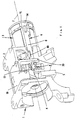
- 1 denotes a motor vehicle steering wheel lock, which comprises a housing 2 and a lock cylinder 3 which can be actuated by a key (not shown).
- the locking cylinder 3 is connected via a driver 4 to a locking pin 5 which is used to block one
- the steering wheel column of the corresponding vehicle not shown, engages in a corresponding recess in the steering wheel column when the key is removed (locked position).
- a safety device 6 which consists of a web-shaped trigger locking plate 8 extending in the direction of the longitudinal axis 7 of the lock cylinder 3 with a predetermined breaking point 80 and a cylindrical locking pin 9 (FIG. 5).
- the locking pin 9 is prestressed by means of a spring 10 (FIG. 3) and, in its locked position, engages in a recess 11 in the driver 4.
- the locking pin 9 has the shape of a stepped cylinder, the first part 13 of the recess having the smaller diameter 12 11 of the driver 4 is facing.
- the steering wheel lock 1 has a cover plate 19 for covering an assembly opening 190, which has an offset 20 with a recess 21 (FIG. 4).
- the trigger locking plate 8 is guided in the recess 21.
- the trigger locking plate 8 has in this area a groove-shaped recess 22 which is selected to be somewhat longer than the length of the recess 21 of the cover plate 19.
- the cover plate 19 is fastened to the housing 2 in such a way that through the side wall 23 (FIG. 5) the recess 22 has an undercut, so that the trigger locking plate 8 is somewhat in the direction of the longitudinal axis 7 moved, but can not be pulled out of the recess 21.
- the trigger locking plate 8 is supported between the offset 20 and the lock cylinder-side end 200 of the housing in a guide groove 201 of the housing.
- the steering wheel lock may be in the locking position shown in Fig.1, in which the locking pin 5 is in its lower position and engages in a corresponding recess of the steering wheel column, not shown. If an attempt is now made to break the locking cylinder 3 by forceful rotation in order to reach the locking bolt 5 from the inside of the vehicle, the trigger locking plate 8 in the area of the predetermined breaking point 80 is destroyed at the same time.
- the trigger locking plate 8 shifts somewhat in the direction of the broken or twisted locking cylinder 3 and the nose-shaped end 16 of the trigger locking plate 8 releases the spring-loaded locking pin 9, so that the first part 13 of the locking pin 9 is inserted into the recess 11 of the central shaft 4 and the locking bolt 5 is secured in its locked position.
- the part of the trigger locking plate 8 located in the recess cannot be pulled out of the latter.
- an unauthorized third party for example with a special tool, cannot get through the recess 21 to the locking bolt 5 and withdraw it.
- the locking pin need not be configured as a stepped cylinder. Rather, it is only necessary that the locking pin is prevented by a locking member from penetrating into the corresponding recess of the locking pin in the unsecured position of the locking pin.
- the center axis of the trigger plate does not necessarily have to be displaced relative to the center axis of the recess of the offset, as shown in FIG. 4, but the width of the recess can also be approximately equal to that Width of the trigger locking plate in the area of the groove-shaped recess.
- the invention also does not exclusively relate to steering wheel locks with an additional security device 6. Rather, the invention also relates to steering wheel locks in which an additional security device is missing and in which only a securing of the cover plate against unauthorized prying out and removal of the cover plate is required.
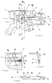
- a corresponding steering wheel lock is shown in FIGS. 6 and 7, which essentially correspond to the exemplary embodiment shown in FIG. 1:
- a trigger locking plate 8' with a recess 22 'and a predetermined breaking point 80' is guided through a corresponding recess 21 'of the offset 20'.
- the trigger locking plate 8 ' is supported in a guide groove 201' of the housing 2 '.
- Fig. 6 shows the slightly raised position of the cover plate 19 'when mounting the lock cylinder with trigger locking plate 8'.
- the second end 16 'of the trigger locking plate 8' can be pushed through the recess 21 'of the offset 20'.
- the cover plate 19 ' is pressed down and fastened (for example caulked), so that the trigger locking plate 8' cannot be pulled out of the recess 21 'even if it breaks, for example by violent rotation of the locking cylinder at the predetermined breaking point 80'. Dismantling of the trigger locking plate 8 'is - like assembly - only possible with the cover plate raised in a defined manner.
Landscapes
- Engineering & Computer Science (AREA)
- Mechanical Engineering (AREA)
- Lock And Its Accessories (AREA)
Priority Applications (1)
| Application Number | Priority Date | Filing Date | Title |
|---|---|---|---|
| EP00203525A EP1069010B1 (fr) | 1996-04-12 | 1997-03-19 | Verrou de direction de véhicule automobile |
Applications Claiming Priority (2)
| Application Number | Priority Date | Filing Date | Title |
|---|---|---|---|
| DE19614436 | 1996-04-12 | ||
| DE19614436A DE19614436C1 (de) | 1996-04-12 | 1996-04-12 | Kraftfahrzeug-Lenkradschloß |
Related Child Applications (1)
| Application Number | Title | Priority Date | Filing Date |
|---|---|---|---|
| EP00203525A Division EP1069010B1 (fr) | 1996-04-12 | 1997-03-19 | Verrou de direction de véhicule automobile |
Publications (3)
| Publication Number | Publication Date |
|---|---|
| EP0806328A2 true EP0806328A2 (fr) | 1997-11-12 |
| EP0806328A3 EP0806328A3 (fr) | 1999-06-23 |
| EP0806328B1 EP0806328B1 (fr) | 2002-05-02 |
Family
ID=7791059
Family Applications (2)
| Application Number | Title | Priority Date | Filing Date |
|---|---|---|---|
| EP00203525A Expired - Lifetime EP1069010B1 (fr) | 1996-04-12 | 1997-03-19 | Verrou de direction de véhicule automobile |
| EP97104683A Expired - Lifetime EP0806328B1 (fr) | 1996-04-12 | 1997-03-19 | Verrou de direction de véhicule automobile |
Family Applications Before (1)
| Application Number | Title | Priority Date | Filing Date |
|---|---|---|---|
| EP00203525A Expired - Lifetime EP1069010B1 (fr) | 1996-04-12 | 1997-03-19 | Verrou de direction de véhicule automobile |
Country Status (3)
| Country | Link |
|---|---|
| EP (2) | EP1069010B1 (fr) |
| DE (3) | DE19614436C1 (fr) |
| ES (2) | ES2184677T3 (fr) |
Cited By (2)
| Publication number | Priority date | Publication date | Assignee | Title |
|---|---|---|---|---|
| WO2002085678A1 (fr) | 2001-04-20 | 2002-10-31 | Huf Hülsbeck & Fürst Gmbh & Co. Kg | Dispositif de verrouillage de colonne de direction pour vehicules automobiles |
| WO2016008761A1 (fr) * | 2014-07-16 | 2016-01-21 | U-Shin France | Antivol pour vehicule automobile |
Families Citing this family (6)
| Publication number | Priority date | Publication date | Assignee | Title |
|---|---|---|---|---|
| DE10247803B3 (de) | 2002-10-14 | 2004-01-29 | Huf Hülsbeck & Fürst Gmbh & Co. Kg | Vorrichtung zum Sperren der Lenkspindel eines Kraftfahrzeugs |
| FR2871759B1 (fr) | 2004-06-17 | 2007-10-19 | Valeo Securite Habitacle Sas | Dispositif antivol de direction a verrou inserable notamment pour vehicule automobile |
| FR2909953B1 (fr) * | 2006-12-19 | 2009-11-20 | Valeo Securite Habitacle | Dispositif antivol a pene verrouillable pour colonne de direction |
| FR2988057B1 (fr) * | 2012-03-14 | 2014-10-24 | Valeo Securite Habitacle | Antivol a supercondamnation pour colonne de direction de vehicule automobile |
| CN102628328A (zh) * | 2012-05-08 | 2012-08-08 | 天合汽车零部件(苏州)有限公司 | 一种机械管柱点火锁 |
| DE102014112816A1 (de) | 2014-09-05 | 2016-03-10 | Huf Hülsbeck & Fürst Gmbh & Co. Kg | Lenkradverriegelung |
Family Cites Families (7)
| Publication number | Priority date | Publication date | Assignee | Title |
|---|---|---|---|---|
| DE2053775C3 (de) * | 1970-11-02 | 1974-02-14 | Daimler-Benz Ag, 7000 Stuttgart | Lenkschloß für Kraftfahrzeuge |
| DE2354135A1 (de) * | 1972-11-02 | 1974-05-16 | Wilmot Breeden Ltd | Diebstahlsicherung, insbesondere fuer kraftfahrzeuge |
| GB2037867B (en) * | 1978-09-22 | 1982-07-14 | Neiman Security Prod | Locks |
| DE3616122C2 (de) * | 1986-05-13 | 1997-05-15 | Ymos Ag Ind Produkte | Lenk- und Zündschloß |
| IT223027Z2 (it) * | 1991-07-09 | 1995-05-25 | Trw Sipea Spa | Bloccasterzo antieffrazione per autoveicoli |
| US5186031A (en) * | 1991-08-20 | 1993-02-16 | Briggs & Stratton Corporation | Self-destruct electrical interlock for cylinder lock and key set |
| DE4226482C2 (de) * | 1992-08-11 | 2002-01-10 | Valeo Deutschland Gmbh & Co | Lenkschloß für ein Kraftfahrzeug |
-
1996
- 1996-04-12 DE DE19614436A patent/DE19614436C1/de not_active Expired - Fee Related
-
1997
- 1997-03-19 EP EP00203525A patent/EP1069010B1/fr not_active Expired - Lifetime
- 1997-03-19 DE DE59707128T patent/DE59707128D1/de not_active Expired - Lifetime
- 1997-03-19 DE DE59708394T patent/DE59708394D1/de not_active Expired - Lifetime
- 1997-03-19 EP EP97104683A patent/EP0806328B1/fr not_active Expired - Lifetime
- 1997-03-19 ES ES00203525T patent/ES2184677T3/es not_active Expired - Lifetime
- 1997-03-19 ES ES97104683T patent/ES2175211T3/es not_active Expired - Lifetime
Cited By (5)
| Publication number | Priority date | Publication date | Assignee | Title |
|---|---|---|---|---|
| WO2002085678A1 (fr) | 2001-04-20 | 2002-10-31 | Huf Hülsbeck & Fürst Gmbh & Co. Kg | Dispositif de verrouillage de colonne de direction pour vehicules automobiles |
| DE10119267C1 (de) * | 2001-04-20 | 2002-11-21 | Huf Huelsbeck & Fuerst Gmbh | Lenkschloss für Fahrzeuge |
| WO2016008761A1 (fr) * | 2014-07-16 | 2016-01-21 | U-Shin France | Antivol pour vehicule automobile |
| FR3023764A1 (fr) * | 2014-07-16 | 2016-01-22 | U Shin France Sas | Antivol pour vehicule automobile |
| CN106715205A (zh) * | 2014-07-16 | 2017-05-24 | 法国有信公司 | 用于机动车辆的防盗设备 |
Also Published As
| Publication number | Publication date |
|---|---|
| DE59708394D1 (de) | 2002-11-07 |
| DE59707128D1 (de) | 2002-06-06 |
| ES2175211T3 (es) | 2002-11-16 |
| EP1069010B1 (fr) | 2002-10-02 |
| ES2184677T3 (es) | 2003-04-16 |
| EP1069010A1 (fr) | 2001-01-17 |
| DE19614436C1 (de) | 1997-06-12 |
| EP0806328A3 (fr) | 1999-06-23 |
| EP0806328B1 (fr) | 2002-05-02 |
Similar Documents
| Publication | Publication Date | Title |
|---|---|---|
| DE69922373T2 (de) | Verschlussvorrichtung und haubenschloss für ein fahrzeug mit einer derartigen verschlussvorrichtung | |
| DE9208698U1 (de) | Lenkradschloß | |
| DE19752519A1 (de) | Verriegelungseinrichtung für Lenkungen von Kraftfahrzeugen | |
| EP0279878A1 (fr) | Serrure électrique pour porte | |
| DE3626014C2 (fr) | ||
| DE102011052960A1 (de) | Türgriffanordnung eines Kraftfahrzeugs | |
| EP1069010B1 (fr) | Verrou de direction de véhicule automobile | |
| DE69916122T2 (de) | Zylinderschloss | |
| EP2993090B2 (fr) | Verrouillage de volant de direction | |
| EP1922459B1 (fr) | Cylindre de fermeture pour fonctions mises en oeuvre dans un véhicule | |
| EP1764293B1 (fr) | Serrure pour frein à disque | |
| EP0721869B1 (fr) | Dispositif de verrouillage pour véhicules | |
| DE19739977C2 (de) | Verriegelungsvorrichtung für eine hinten angelenkte Motorhaube eines Kraftfahrzeuges | |
| DD230842A1 (de) | Vorrichtung zum absperren des handbremshebels von kraftfahrzeugen | |
| DE19921889B4 (de) | Zündschloß für ein Kraftfahrzeug | |
| DE4339654C3 (de) | Kraftfahrzeugtürverschluß | |
| DE2655660A1 (de) | Vorrichtung zur sicherung eines kraftfahrzeuges gegen diebstahl von fahrzeugraedern sowie unbefugtes abschleppen | |
| EP0585735B1 (fr) | Serrure de fixation pour cylindre d'un verrou de sécurité | |
| EP0724055B1 (fr) | Fixation de sécurité contre l'effraction pour un dispositif de contrôle avec une serrure cylindrique | |
| DE69401367T2 (de) | Diebstahlsicherung für ein Fahrzeug | |
| DE19704812B4 (de) | Kraftfahrzeugtürschloß | |
| DE3816863A1 (de) | Diebstahlsicherung eines versenkt anzuordnenden einbaugeraetes | |
| CH674542A5 (en) | Security lock cylinder - has core with rear end flange inserted from rear and front covering head | |
| DE10254047A1 (de) | Stangenförmiges Verbindungsteil zur drehbaren Verbindung des Zylinderkerns eines Schließzylinders und eines Schlosses | |
| DE19708720B4 (de) | Schloß für eine Türblatt-Zargen-Kombination |
Legal Events
| Date | Code | Title | Description |
|---|---|---|---|
| PUAI | Public reference made under article 153(3) epc to a published international application that has entered the european phase |
Free format text: ORIGINAL CODE: 0009012 |
|
| AK | Designated contracting states |
Kind code of ref document: A2 Designated state(s): DE ES FR GB IT SE |
|
| PUAL | Search report despatched |
Free format text: ORIGINAL CODE: 0009013 |
|
| AK | Designated contracting states |
Kind code of ref document: A3 Designated state(s): DE ES FR GB IT SE |
|
| 17P | Request for examination filed |
Effective date: 19990818 |
|
| GRAG | Despatch of communication of intention to grant |
Free format text: ORIGINAL CODE: EPIDOS AGRA |
|
| GRAG | Despatch of communication of intention to grant |
Free format text: ORIGINAL CODE: EPIDOS AGRA |
|
| GRAH | Despatch of communication of intention to grant a patent |
Free format text: ORIGINAL CODE: EPIDOS IGRA |
|
| 17Q | First examination report despatched |
Effective date: 20010821 |
|
| REG | Reference to a national code |
Ref country code: GB Ref legal event code: IF02 |
|
| GRAH | Despatch of communication of intention to grant a patent |
Free format text: ORIGINAL CODE: EPIDOS IGRA |
|
| GRAA | (expected) grant |
Free format text: ORIGINAL CODE: 0009210 |
|
| AK | Designated contracting states |
Kind code of ref document: B1 Designated state(s): DE ES FR GB IT SE |
|
| REG | Reference to a national code |
Ref country code: GB Ref legal event code: FG4D Free format text: NOT ENGLISH |
|
| GBT | Gb: translation of ep patent filed (gb section 77(6)(a)/1977) |
Effective date: 20020502 |
|
| REF | Corresponds to: |
Ref document number: 59707128 Country of ref document: DE Date of ref document: 20020606 |
|
| ET | Fr: translation filed | ||
| REG | Reference to a national code |
Ref country code: ES Ref legal event code: FG2A Ref document number: 2175211 Country of ref document: ES Kind code of ref document: T3 |
|
| PLBE | No opposition filed within time limit |
Free format text: ORIGINAL CODE: 0009261 |
|
| STAA | Information on the status of an ep patent application or granted ep patent |
Free format text: STATUS: NO OPPOSITION FILED WITHIN TIME LIMIT |
|
| 26N | No opposition filed |
Effective date: 20030204 |
|
| REG | Reference to a national code |
Ref country code: FR Ref legal event code: PLFP Year of fee payment: 20 |
|
| PGFP | Annual fee paid to national office [announced via postgrant information from national office to epo] |
Ref country code: ES Payment date: 20160329 Year of fee payment: 20 Ref country code: DE Payment date: 20160316 Year of fee payment: 20 |
|
| PGFP | Annual fee paid to national office [announced via postgrant information from national office to epo] |
Ref country code: GB Payment date: 20160318 Year of fee payment: 20 Ref country code: SE Payment date: 20160318 Year of fee payment: 20 |
|
| PGFP | Annual fee paid to national office [announced via postgrant information from national office to epo] |
Ref country code: IT Payment date: 20160317 Year of fee payment: 20 Ref country code: FR Payment date: 20160331 Year of fee payment: 20 |
|
| REG | Reference to a national code |
Ref country code: DE Ref legal event code: R071 Ref document number: 59707128 Country of ref document: DE |
|
| REG | Reference to a national code |
Ref country code: GB Ref legal event code: PE20 Expiry date: 20170318 |
|
| REG | Reference to a national code |
Ref country code: SE Ref legal event code: EUG |
|
| PG25 | Lapsed in a contracting state [announced via postgrant information from national office to epo] |
Ref country code: GB Free format text: LAPSE BECAUSE OF EXPIRATION OF PROTECTION Effective date: 20170318 |
|
| REG | Reference to a national code |
Ref country code: ES Ref legal event code: FD2A Effective date: 20180508 |
|
| PG25 | Lapsed in a contracting state [announced via postgrant information from national office to epo] |
Ref country code: ES Free format text: LAPSE BECAUSE OF EXPIRATION OF PROTECTION Effective date: 20170320 |