EP0806315B1 - Hybridantriebssystem mit elektrischer Kupplung zur differentiellen Antriebskraftverteilung - Google Patents
Hybridantriebssystem mit elektrischer Kupplung zur differentiellen Antriebskraftverteilung Download PDFInfo
- Publication number
- EP0806315B1 EP0806315B1 EP96303258A EP96303258A EP0806315B1 EP 0806315 B1 EP0806315 B1 EP 0806315B1 EP 96303258 A EP96303258 A EP 96303258A EP 96303258 A EP96303258 A EP 96303258A EP 0806315 B1 EP0806315 B1 EP 0806315B1
- Authority
- EP
- European Patent Office
- Prior art keywords
- electromagnetic coupling
- coupling device
- engine
- section load
- drive
- Prior art date
- Legal status (The legal status is an assumption and is not a legal conclusion. Google has not performed a legal analysis and makes no representation as to the accuracy of the status listed.)
- Expired - Lifetime
Links
Images


Classifications
-
- B—PERFORMING OPERATIONS; TRANSPORTING
- B60—VEHICLES IN GENERAL
- B60W—CONJOINT CONTROL OF VEHICLE SUB-UNITS OF DIFFERENT TYPE OR DIFFERENT FUNCTION; CONTROL SYSTEMS SPECIALLY ADAPTED FOR HYBRID VEHICLES; ROAD VEHICLE DRIVE CONTROL SYSTEMS FOR PURPOSES NOT RELATED TO THE CONTROL OF A PARTICULAR SUB-UNIT
- B60W20/00—Control systems specially adapted for hybrid vehicles
- B60W20/10—Controlling the power contribution of each of the prime movers to meet required power demand
-
- B—PERFORMING OPERATIONS; TRANSPORTING
- B60—VEHICLES IN GENERAL
- B60K—ARRANGEMENT OR MOUNTING OF PROPULSION UNITS OR OF TRANSMISSIONS IN VEHICLES; ARRANGEMENT OR MOUNTING OF PLURAL DIVERSE PRIME-MOVERS IN VEHICLES; AUXILIARY DRIVES FOR VEHICLES; INSTRUMENTATION OR DASHBOARDS FOR VEHICLES; ARRANGEMENTS IN CONNECTION WITH COOLING, AIR INTAKE, GAS EXHAUST OR FUEL SUPPLY OF PROPULSION UNITS IN VEHICLES
- B60K6/00—Arrangement or mounting of plural diverse prime-movers for mutual or common propulsion, e.g. hybrid propulsion systems comprising electric motors and internal combustion engines
- B60K6/20—Arrangement or mounting of plural diverse prime-movers for mutual or common propulsion, e.g. hybrid propulsion systems comprising electric motors and internal combustion engines the prime-movers consisting of electric motors and internal combustion engines, e.g. HEVs
- B60K6/22—Arrangement or mounting of plural diverse prime-movers for mutual or common propulsion, e.g. hybrid propulsion systems comprising electric motors and internal combustion engines the prime-movers consisting of electric motors and internal combustion engines, e.g. HEVs characterised by apparatus, components or means specially adapted for HEVs
- B60K6/36—Arrangement or mounting of plural diverse prime-movers for mutual or common propulsion, e.g. hybrid propulsion systems comprising electric motors and internal combustion engines the prime-movers consisting of electric motors and internal combustion engines, e.g. HEVs characterised by apparatus, components or means specially adapted for HEVs characterised by the transmission gearings
- B60K6/365—Arrangement or mounting of plural diverse prime-movers for mutual or common propulsion, e.g. hybrid propulsion systems comprising electric motors and internal combustion engines the prime-movers consisting of electric motors and internal combustion engines, e.g. HEVs characterised by apparatus, components or means specially adapted for HEVs characterised by the transmission gearings with the gears having orbital motion
-
- B—PERFORMING OPERATIONS; TRANSPORTING
- B60—VEHICLES IN GENERAL
- B60K—ARRANGEMENT OR MOUNTING OF PROPULSION UNITS OR OF TRANSMISSIONS IN VEHICLES; ARRANGEMENT OR MOUNTING OF PLURAL DIVERSE PRIME-MOVERS IN VEHICLES; AUXILIARY DRIVES FOR VEHICLES; INSTRUMENTATION OR DASHBOARDS FOR VEHICLES; ARRANGEMENTS IN CONNECTION WITH COOLING, AIR INTAKE, GAS EXHAUST OR FUEL SUPPLY OF PROPULSION UNITS IN VEHICLES
- B60K23/00—Arrangement or mounting of control devices for vehicle transmissions, or parts thereof, not otherwise provided for
- B60K23/08—Arrangement or mounting of control devices for vehicle transmissions, or parts thereof, not otherwise provided for for changing number of driven wheels, for switching from driving one axle to driving two or more axles
-
- B—PERFORMING OPERATIONS; TRANSPORTING
- B60—VEHICLES IN GENERAL
- B60K—ARRANGEMENT OR MOUNTING OF PROPULSION UNITS OR OF TRANSMISSIONS IN VEHICLES; ARRANGEMENT OR MOUNTING OF PLURAL DIVERSE PRIME-MOVERS IN VEHICLES; AUXILIARY DRIVES FOR VEHICLES; INSTRUMENTATION OR DASHBOARDS FOR VEHICLES; ARRANGEMENTS IN CONNECTION WITH COOLING, AIR INTAKE, GAS EXHAUST OR FUEL SUPPLY OF PROPULSION UNITS IN VEHICLES
- B60K6/00—Arrangement or mounting of plural diverse prime-movers for mutual or common propulsion, e.g. hybrid propulsion systems comprising electric motors and internal combustion engines
- B60K6/20—Arrangement or mounting of plural diverse prime-movers for mutual or common propulsion, e.g. hybrid propulsion systems comprising electric motors and internal combustion engines the prime-movers consisting of electric motors and internal combustion engines, e.g. HEVs
- B60K6/42—Arrangement or mounting of plural diverse prime-movers for mutual or common propulsion, e.g. hybrid propulsion systems comprising electric motors and internal combustion engines the prime-movers consisting of electric motors and internal combustion engines, e.g. HEVs characterised by the architecture of the hybrid electric vehicle
- B60K6/44—Series-parallel type
- B60K6/445—Differential gearing distribution type
-
- B—PERFORMING OPERATIONS; TRANSPORTING
- B60—VEHICLES IN GENERAL
- B60K—ARRANGEMENT OR MOUNTING OF PROPULSION UNITS OR OF TRANSMISSIONS IN VEHICLES; ARRANGEMENT OR MOUNTING OF PLURAL DIVERSE PRIME-MOVERS IN VEHICLES; AUXILIARY DRIVES FOR VEHICLES; INSTRUMENTATION OR DASHBOARDS FOR VEHICLES; ARRANGEMENTS IN CONNECTION WITH COOLING, AIR INTAKE, GAS EXHAUST OR FUEL SUPPLY OF PROPULSION UNITS IN VEHICLES
- B60K6/00—Arrangement or mounting of plural diverse prime-movers for mutual or common propulsion, e.g. hybrid propulsion systems comprising electric motors and internal combustion engines
- B60K6/20—Arrangement or mounting of plural diverse prime-movers for mutual or common propulsion, e.g. hybrid propulsion systems comprising electric motors and internal combustion engines the prime-movers consisting of electric motors and internal combustion engines, e.g. HEVs
- B60K6/42—Arrangement or mounting of plural diverse prime-movers for mutual or common propulsion, e.g. hybrid propulsion systems comprising electric motors and internal combustion engines the prime-movers consisting of electric motors and internal combustion engines, e.g. HEVs characterised by the architecture of the hybrid electric vehicle
- B60K6/48—Parallel type
-
- B—PERFORMING OPERATIONS; TRANSPORTING
- B60—VEHICLES IN GENERAL
- B60K—ARRANGEMENT OR MOUNTING OF PROPULSION UNITS OR OF TRANSMISSIONS IN VEHICLES; ARRANGEMENT OR MOUNTING OF PLURAL DIVERSE PRIME-MOVERS IN VEHICLES; AUXILIARY DRIVES FOR VEHICLES; INSTRUMENTATION OR DASHBOARDS FOR VEHICLES; ARRANGEMENTS IN CONNECTION WITH COOLING, AIR INTAKE, GAS EXHAUST OR FUEL SUPPLY OF PROPULSION UNITS IN VEHICLES
- B60K6/00—Arrangement or mounting of plural diverse prime-movers for mutual or common propulsion, e.g. hybrid propulsion systems comprising electric motors and internal combustion engines
- B60K6/20—Arrangement or mounting of plural diverse prime-movers for mutual or common propulsion, e.g. hybrid propulsion systems comprising electric motors and internal combustion engines the prime-movers consisting of electric motors and internal combustion engines, e.g. HEVs
- B60K6/50—Architecture of the driveline characterised by arrangement or kind of transmission units
- B60K6/52—Driving a plurality of drive axles, e.g. four-wheel drive
-
- B—PERFORMING OPERATIONS; TRANSPORTING
- B60—VEHICLES IN GENERAL
- B60L—PROPULSION OF ELECTRICALLY-PROPELLED VEHICLES; SUPPLYING ELECTRIC POWER FOR AUXILIARY EQUIPMENT OF ELECTRICALLY-PROPELLED VEHICLES; ELECTRODYNAMIC BRAKE SYSTEMS FOR VEHICLES IN GENERAL; MAGNETIC SUSPENSION OR LEVITATION FOR VEHICLES; MONITORING OPERATING VARIABLES OF ELECTRICALLY-PROPELLED VEHICLES; ELECTRIC SAFETY DEVICES FOR ELECTRICALLY-PROPELLED VEHICLES
- B60L50/00—Electric propulsion with power supplied within the vehicle
- B60L50/10—Electric propulsion with power supplied within the vehicle using propulsion power supplied by engine-driven generators, e.g. generators driven by combustion engines
- B60L50/16—Electric propulsion with power supplied within the vehicle using propulsion power supplied by engine-driven generators, e.g. generators driven by combustion engines with provision for separate direct mechanical propulsion
-
- B—PERFORMING OPERATIONS; TRANSPORTING
- B60—VEHICLES IN GENERAL
- B60W—CONJOINT CONTROL OF VEHICLE SUB-UNITS OF DIFFERENT TYPE OR DIFFERENT FUNCTION; CONTROL SYSTEMS SPECIALLY ADAPTED FOR HYBRID VEHICLES; ROAD VEHICLE DRIVE CONTROL SYSTEMS FOR PURPOSES NOT RELATED TO THE CONTROL OF A PARTICULAR SUB-UNIT
- B60W10/00—Conjoint control of vehicle sub-units of different type or different function
- B60W10/02—Conjoint control of vehicle sub-units of different type or different function including control of driveline clutches
-
- B—PERFORMING OPERATIONS; TRANSPORTING
- B60—VEHICLES IN GENERAL
- B60W—CONJOINT CONTROL OF VEHICLE SUB-UNITS OF DIFFERENT TYPE OR DIFFERENT FUNCTION; CONTROL SYSTEMS SPECIALLY ADAPTED FOR HYBRID VEHICLES; ROAD VEHICLE DRIVE CONTROL SYSTEMS FOR PURPOSES NOT RELATED TO THE CONTROL OF A PARTICULAR SUB-UNIT
- B60W10/00—Conjoint control of vehicle sub-units of different type or different function
- B60W10/04—Conjoint control of vehicle sub-units of different type or different function including control of propulsion units
- B60W10/06—Conjoint control of vehicle sub-units of different type or different function including control of propulsion units including control of combustion engines
-
- B—PERFORMING OPERATIONS; TRANSPORTING
- B60—VEHICLES IN GENERAL
- B60W—CONJOINT CONTROL OF VEHICLE SUB-UNITS OF DIFFERENT TYPE OR DIFFERENT FUNCTION; CONTROL SYSTEMS SPECIALLY ADAPTED FOR HYBRID VEHICLES; ROAD VEHICLE DRIVE CONTROL SYSTEMS FOR PURPOSES NOT RELATED TO THE CONTROL OF A PARTICULAR SUB-UNIT
- B60W10/00—Conjoint control of vehicle sub-units of different type or different function
- B60W10/04—Conjoint control of vehicle sub-units of different type or different function including control of propulsion units
- B60W10/08—Conjoint control of vehicle sub-units of different type or different function including control of propulsion units including control of electric propulsion units, e.g. motors or generators
-
- B—PERFORMING OPERATIONS; TRANSPORTING
- B60—VEHICLES IN GENERAL
- B60W—CONJOINT CONTROL OF VEHICLE SUB-UNITS OF DIFFERENT TYPE OR DIFFERENT FUNCTION; CONTROL SYSTEMS SPECIALLY ADAPTED FOR HYBRID VEHICLES; ROAD VEHICLE DRIVE CONTROL SYSTEMS FOR PURPOSES NOT RELATED TO THE CONTROL OF A PARTICULAR SUB-UNIT
- B60W10/00—Conjoint control of vehicle sub-units of different type or different function
- B60W10/24—Conjoint control of vehicle sub-units of different type or different function including control of energy storage means
- B60W10/26—Conjoint control of vehicle sub-units of different type or different function including control of energy storage means for electrical energy, e.g. batteries or capacitors
-
- B—PERFORMING OPERATIONS; TRANSPORTING
- B60—VEHICLES IN GENERAL
- B60W—CONJOINT CONTROL OF VEHICLE SUB-UNITS OF DIFFERENT TYPE OR DIFFERENT FUNCTION; CONTROL SYSTEMS SPECIALLY ADAPTED FOR HYBRID VEHICLES; ROAD VEHICLE DRIVE CONTROL SYSTEMS FOR PURPOSES NOT RELATED TO THE CONTROL OF A PARTICULAR SUB-UNIT
- B60W20/00—Control systems specially adapted for hybrid vehicles
-
- B—PERFORMING OPERATIONS; TRANSPORTING
- B60—VEHICLES IN GENERAL
- B60K—ARRANGEMENT OR MOUNTING OF PROPULSION UNITS OR OF TRANSMISSIONS IN VEHICLES; ARRANGEMENT OR MOUNTING OF PLURAL DIVERSE PRIME-MOVERS IN VEHICLES; AUXILIARY DRIVES FOR VEHICLES; INSTRUMENTATION OR DASHBOARDS FOR VEHICLES; ARRANGEMENTS IN CONNECTION WITH COOLING, AIR INTAKE, GAS EXHAUST OR FUEL SUPPLY OF PROPULSION UNITS IN VEHICLES
- B60K17/00—Arrangement or mounting of transmissions in vehicles
- B60K17/04—Arrangement or mounting of transmissions in vehicles characterised by arrangement, location or kind of gearing
- B60K17/16—Arrangement or mounting of transmissions in vehicles characterised by arrangement, location or kind of gearing of differential gearing
-
- B—PERFORMING OPERATIONS; TRANSPORTING
- B60—VEHICLES IN GENERAL
- B60K—ARRANGEMENT OR MOUNTING OF PROPULSION UNITS OR OF TRANSMISSIONS IN VEHICLES; ARRANGEMENT OR MOUNTING OF PLURAL DIVERSE PRIME-MOVERS IN VEHICLES; AUXILIARY DRIVES FOR VEHICLES; INSTRUMENTATION OR DASHBOARDS FOR VEHICLES; ARRANGEMENTS IN CONNECTION WITH COOLING, AIR INTAKE, GAS EXHAUST OR FUEL SUPPLY OF PROPULSION UNITS IN VEHICLES
- B60K17/00—Arrangement or mounting of transmissions in vehicles
- B60K17/34—Arrangement or mounting of transmissions in vehicles for driving both front and rear wheels, e.g. four wheel drive vehicles
- B60K17/356—Arrangement or mounting of transmissions in vehicles for driving both front and rear wheels, e.g. four wheel drive vehicles having fluid or electric motor, for driving one or more wheels
-
- B—PERFORMING OPERATIONS; TRANSPORTING
- B60—VEHICLES IN GENERAL
- B60K—ARRANGEMENT OR MOUNTING OF PROPULSION UNITS OR OF TRANSMISSIONS IN VEHICLES; ARRANGEMENT OR MOUNTING OF PLURAL DIVERSE PRIME-MOVERS IN VEHICLES; AUXILIARY DRIVES FOR VEHICLES; INSTRUMENTATION OR DASHBOARDS FOR VEHICLES; ARRANGEMENTS IN CONNECTION WITH COOLING, AIR INTAKE, GAS EXHAUST OR FUEL SUPPLY OF PROPULSION UNITS IN VEHICLES
- B60K6/00—Arrangement or mounting of plural diverse prime-movers for mutual or common propulsion, e.g. hybrid propulsion systems comprising electric motors and internal combustion engines
- B60K6/20—Arrangement or mounting of plural diverse prime-movers for mutual or common propulsion, e.g. hybrid propulsion systems comprising electric motors and internal combustion engines the prime-movers consisting of electric motors and internal combustion engines, e.g. HEVs
- B60K6/22—Arrangement or mounting of plural diverse prime-movers for mutual or common propulsion, e.g. hybrid propulsion systems comprising electric motors and internal combustion engines the prime-movers consisting of electric motors and internal combustion engines, e.g. HEVs characterised by apparatus, components or means specially adapted for HEVs
- B60K6/26—Arrangement or mounting of plural diverse prime-movers for mutual or common propulsion, e.g. hybrid propulsion systems comprising electric motors and internal combustion engines the prime-movers consisting of electric motors and internal combustion engines, e.g. HEVs characterised by apparatus, components or means specially adapted for HEVs characterised by the motors or the generators
- B60K2006/262—Arrangement or mounting of plural diverse prime-movers for mutual or common propulsion, e.g. hybrid propulsion systems comprising electric motors and internal combustion engines the prime-movers consisting of electric motors and internal combustion engines, e.g. HEVs characterised by apparatus, components or means specially adapted for HEVs characterised by the motors or the generators the motor or generator are used as clutch, e.g. between engine and driveshaft
-
- B—PERFORMING OPERATIONS; TRANSPORTING
- B60—VEHICLES IN GENERAL
- B60K—ARRANGEMENT OR MOUNTING OF PROPULSION UNITS OR OF TRANSMISSIONS IN VEHICLES; ARRANGEMENT OR MOUNTING OF PLURAL DIVERSE PRIME-MOVERS IN VEHICLES; AUXILIARY DRIVES FOR VEHICLES; INSTRUMENTATION OR DASHBOARDS FOR VEHICLES; ARRANGEMENTS IN CONNECTION WITH COOLING, AIR INTAKE, GAS EXHAUST OR FUEL SUPPLY OF PROPULSION UNITS IN VEHICLES
- B60K6/00—Arrangement or mounting of plural diverse prime-movers for mutual or common propulsion, e.g. hybrid propulsion systems comprising electric motors and internal combustion engines
- B60K6/20—Arrangement or mounting of plural diverse prime-movers for mutual or common propulsion, e.g. hybrid propulsion systems comprising electric motors and internal combustion engines the prime-movers consisting of electric motors and internal combustion engines, e.g. HEVs
- B60K6/22—Arrangement or mounting of plural diverse prime-movers for mutual or common propulsion, e.g. hybrid propulsion systems comprising electric motors and internal combustion engines the prime-movers consisting of electric motors and internal combustion engines, e.g. HEVs characterised by apparatus, components or means specially adapted for HEVs
- B60K6/26—Arrangement or mounting of plural diverse prime-movers for mutual or common propulsion, e.g. hybrid propulsion systems comprising electric motors and internal combustion engines the prime-movers consisting of electric motors and internal combustion engines, e.g. HEVs characterised by apparatus, components or means specially adapted for HEVs characterised by the motors or the generators
- B60K2006/268—Electric drive motor starts the engine, i.e. used as starter motor
-
- B—PERFORMING OPERATIONS; TRANSPORTING
- B60—VEHICLES IN GENERAL
- B60L—PROPULSION OF ELECTRICALLY-PROPELLED VEHICLES; SUPPLYING ELECTRIC POWER FOR AUXILIARY EQUIPMENT OF ELECTRICALLY-PROPELLED VEHICLES; ELECTRODYNAMIC BRAKE SYSTEMS FOR VEHICLES IN GENERAL; MAGNETIC SUSPENSION OR LEVITATION FOR VEHICLES; MONITORING OPERATING VARIABLES OF ELECTRICALLY-PROPELLED VEHICLES; ELECTRIC SAFETY DEVICES FOR ELECTRICALLY-PROPELLED VEHICLES
- B60L2240/00—Control parameters of input or output; Target parameters
- B60L2240/40—Drive Train control parameters
- B60L2240/44—Drive Train control parameters related to combustion engines
- B60L2240/441—Speed
-
- B—PERFORMING OPERATIONS; TRANSPORTING
- B60—VEHICLES IN GENERAL
- B60W—CONJOINT CONTROL OF VEHICLE SUB-UNITS OF DIFFERENT TYPE OR DIFFERENT FUNCTION; CONTROL SYSTEMS SPECIALLY ADAPTED FOR HYBRID VEHICLES; ROAD VEHICLE DRIVE CONTROL SYSTEMS FOR PURPOSES NOT RELATED TO THE CONTROL OF A PARTICULAR SUB-UNIT
- B60W2510/00—Input parameters relating to a particular sub-units
- B60W2510/06—Combustion engines, Gas turbines
- B60W2510/0638—Engine speed
-
- B—PERFORMING OPERATIONS; TRANSPORTING
- B60—VEHICLES IN GENERAL
- B60W—CONJOINT CONTROL OF VEHICLE SUB-UNITS OF DIFFERENT TYPE OR DIFFERENT FUNCTION; CONTROL SYSTEMS SPECIALLY ADAPTED FOR HYBRID VEHICLES; ROAD VEHICLE DRIVE CONTROL SYSTEMS FOR PURPOSES NOT RELATED TO THE CONTROL OF A PARTICULAR SUB-UNIT
- B60W2710/00—Output or target parameters relating to a particular sub-units
- B60W2710/06—Combustion engines, Gas turbines
- B60W2710/0605—Throttle position
-
- B—PERFORMING OPERATIONS; TRANSPORTING
- B60—VEHICLES IN GENERAL
- B60W—CONJOINT CONTROL OF VEHICLE SUB-UNITS OF DIFFERENT TYPE OR DIFFERENT FUNCTION; CONTROL SYSTEMS SPECIALLY ADAPTED FOR HYBRID VEHICLES; ROAD VEHICLE DRIVE CONTROL SYSTEMS FOR PURPOSES NOT RELATED TO THE CONTROL OF A PARTICULAR SUB-UNIT
- B60W2710/00—Output or target parameters relating to a particular sub-units
- B60W2710/06—Combustion engines, Gas turbines
- B60W2710/0644—Engine speed
-
- Y—GENERAL TAGGING OF NEW TECHNOLOGICAL DEVELOPMENTS; GENERAL TAGGING OF CROSS-SECTIONAL TECHNOLOGIES SPANNING OVER SEVERAL SECTIONS OF THE IPC; TECHNICAL SUBJECTS COVERED BY FORMER USPC CROSS-REFERENCE ART COLLECTIONS [XRACs] AND DIGESTS
- Y02—TECHNOLOGIES OR APPLICATIONS FOR MITIGATION OR ADAPTATION AGAINST CLIMATE CHANGE
- Y02T—CLIMATE CHANGE MITIGATION TECHNOLOGIES RELATED TO TRANSPORTATION
- Y02T10/00—Road transport of goods or passengers
- Y02T10/60—Other road transportation technologies with climate change mitigation effect
- Y02T10/62—Hybrid vehicles
-
- Y—GENERAL TAGGING OF NEW TECHNOLOGICAL DEVELOPMENTS; GENERAL TAGGING OF CROSS-SECTIONAL TECHNOLOGIES SPANNING OVER SEVERAL SECTIONS OF THE IPC; TECHNICAL SUBJECTS COVERED BY FORMER USPC CROSS-REFERENCE ART COLLECTIONS [XRACs] AND DIGESTS
- Y02—TECHNOLOGIES OR APPLICATIONS FOR MITIGATION OR ADAPTATION AGAINST CLIMATE CHANGE
- Y02T—CLIMATE CHANGE MITIGATION TECHNOLOGIES RELATED TO TRANSPORTATION
- Y02T10/00—Road transport of goods or passengers
- Y02T10/60—Other road transportation technologies with climate change mitigation effect
- Y02T10/70—Energy storage systems for electromobility, e.g. batteries
-
- Y—GENERAL TAGGING OF NEW TECHNOLOGICAL DEVELOPMENTS; GENERAL TAGGING OF CROSS-SECTIONAL TECHNOLOGIES SPANNING OVER SEVERAL SECTIONS OF THE IPC; TECHNICAL SUBJECTS COVERED BY FORMER USPC CROSS-REFERENCE ART COLLECTIONS [XRACs] AND DIGESTS
- Y02—TECHNOLOGIES OR APPLICATIONS FOR MITIGATION OR ADAPTATION AGAINST CLIMATE CHANGE
- Y02T—CLIMATE CHANGE MITIGATION TECHNOLOGIES RELATED TO TRANSPORTATION
- Y02T10/00—Road transport of goods or passengers
- Y02T10/60—Other road transportation technologies with climate change mitigation effect
- Y02T10/7072—Electromobility specific charging systems or methods for batteries, ultracapacitors, supercapacitors or double-layer capacitors
-
- Y—GENERAL TAGGING OF NEW TECHNOLOGICAL DEVELOPMENTS; GENERAL TAGGING OF CROSS-SECTIONAL TECHNOLOGIES SPANNING OVER SEVERAL SECTIONS OF THE IPC; TECHNICAL SUBJECTS COVERED BY FORMER USPC CROSS-REFERENCE ART COLLECTIONS [XRACs] AND DIGESTS
- Y10—TECHNICAL SUBJECTS COVERED BY FORMER USPC
- Y10S—TECHNICAL SUBJECTS COVERED BY FORMER USPC CROSS-REFERENCE ART COLLECTIONS [XRACs] AND DIGESTS
- Y10S903/00—Hybrid electric vehicles, HEVS
- Y10S903/902—Prime movers comprising electrical and internal combustion motors
- Y10S903/903—Prime movers comprising electrical and internal combustion motors having energy storing means, e.g. battery, capacitor
- Y10S903/904—Component specially adapted for hev
- Y10S903/909—Gearing
- Y10S903/91—Orbital, e.g. planetary gears
-
- Y—GENERAL TAGGING OF NEW TECHNOLOGICAL DEVELOPMENTS; GENERAL TAGGING OF CROSS-SECTIONAL TECHNOLOGIES SPANNING OVER SEVERAL SECTIONS OF THE IPC; TECHNICAL SUBJECTS COVERED BY FORMER USPC CROSS-REFERENCE ART COLLECTIONS [XRACs] AND DIGESTS
- Y10—TECHNICAL SUBJECTS COVERED BY FORMER USPC
- Y10S—TECHNICAL SUBJECTS COVERED BY FORMER USPC CROSS-REFERENCE ART COLLECTIONS [XRACs] AND DIGESTS
- Y10S903/00—Hybrid electric vehicles, HEVS
- Y10S903/902—Prime movers comprising electrical and internal combustion motors
- Y10S903/903—Prime movers comprising electrical and internal combustion motors having energy storing means, e.g. battery, capacitor
- Y10S903/904—Component specially adapted for hev
- Y10S903/915—Specific drive or transmission adapted for hev
- Y10S903/916—Specific drive or transmission adapted for hev with plurality of drive axles
-
- Y—GENERAL TAGGING OF NEW TECHNOLOGICAL DEVELOPMENTS; GENERAL TAGGING OF CROSS-SECTIONAL TECHNOLOGIES SPANNING OVER SEVERAL SECTIONS OF THE IPC; TECHNICAL SUBJECTS COVERED BY FORMER USPC CROSS-REFERENCE ART COLLECTIONS [XRACs] AND DIGESTS
- Y10—TECHNICAL SUBJECTS COVERED BY FORMER USPC
- Y10S—TECHNICAL SUBJECTS COVERED BY FORMER USPC CROSS-REFERENCE ART COLLECTIONS [XRACs] AND DIGESTS
- Y10S903/00—Hybrid electric vehicles, HEVS
- Y10S903/902—Prime movers comprising electrical and internal combustion motors
- Y10S903/903—Prime movers comprising electrical and internal combustion motors having energy storing means, e.g. battery, capacitor
- Y10S903/946—Characterized by control of driveline clutch
Definitions
- the disclosed distributed differential coupling combined power system of the invention permits the output power from the output shaft of an engine (or other rotational power source) to not only drive a front section load, but also to be combined with an electromagnetic coupling device to drive a rear section load.
- the electromagnetic coupling device is constituted by an AC or DC, brushed or brushless electric machine, and is a two-end structure. It includes a rotational field generating structure and a rotor, and the rotor shaft (or the field rotating shaft) is used as the output shaft to form an electromagnetic coupling device, while the other end is coupled with the engine output shaft through the transmission gear system.
- This design is capable of adding the power and speed of the engine output to the output generated by the electromagnetic coupling device itself to drive the rear load without being affected by the speed relationship between the two. In general, it has a smaller system volume and saves the cost and space in comparison with other combined power systems.
- GB-A-2 275 309 describes a known differential combined power distribution system, according the preamble of claim 1.
- the distributed differential coupling combined power distribution system of the invention may be used in driving vehicles, ships, flying machines or other mechanical, industrial, or processing equipment which require a rotational power source.
- the power system involves the rotational output shaft of a internal combustion engine (or other rotational power sources), and is not only used to drive a front section load directly or through transmission devices such as transmission gears, belts, chains, or the couplers, but is also coupled with the input shaft of an electromagnetic coupling device to drive the rear section load.
- the electromagnetic coupling is a two-end structure, and is respectively combined with a stator and rotor structure to be controlled by an operating device for generating motor driving functions when an input current is applied to the electromagnetic coupling device or for operating variable speed coupling functions through the output current when employed as a generator, or for use in starting the engine and as a power regeneration brake, particularly when the engine is the main transmission power source, to charge the battery through the difference between the speed of the rotational field generated by the stator and the speed of the rotor, the speed difference with the rear load section being thereby adjusted by controlling the charging current.
- the engine can be at a constant speed or at a speed which is partially adjustable to maintain a working speed having a higher operating efficiency and lower pollution, with a portion of the differential speed output power generated through the electromagnetic coupling device being used for driving the load while the remaining part of the power is converted through the generator function of the electromagnetic coupling device to charge the battery.
- the electromagnetic coupling thereby promotes engine efficiency during variable speed driving at low driving speeds while acquiring charging power for the battery and reducing pollution, and in addition to providing a variable speed coupling, the electromagnetic coupling can also be used as a driving motor to generate a rotational output for driving the load independently of or together with the engine.
- Figure 1 is a schematic diagram of the system of a first preferred embodiment.
- Figure 2 is a schematic diagram of a first variation of the system of Figure 1.
- Figure 3 is a schematic diagram of a second variation of the system of Figure 1.
- Figure 4 is a schematic diagram of a third variation of the system of Figure 1.
- Figure 5 is a schematic diagram of a fourth variation of the system of Figure 1.
- Figure 6 is a schematic diagram of a fifth variation of the system of Figure 1.
- Figure 7 is a schematic diagram of a sixth variation of the system of Figure 1.
- Figure 8 is a schematic diagram of a seventh variation of the system of Figure 1.
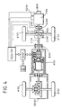
- Figure 1 shows a preferred embodiment of a distributed differential coupling combined power system, including the following principal elements:
- Figure 1 includes the following elements:
- FIG. 2 shows the first application of the system of Figure 1.
- clutch CL104 and brake B102 are both eliminated, and the system functions are delineated in Table 2.
- FIG. 3 shows the second application of the system of Figure 1.
- clutch CL104 and brake B102 are both eliminated, and the system functions are delineated in Table 3.
- Figure 4 shows the third application of the system of Figure 1: It discloses an application in which B102, and clutches CL101 and CL104 are eliminated, and the system functions are delineated in Table 4.
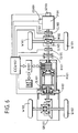
- Figure 5 shows the fourth application of the system of Figure 1: it discloses an application in which an additional clutch CL105 is installed between the rear section output middle shaft and the middle transmission device while clutch CL103 is reserved for controlling the front section load or replaced by a speed change shift of the middle transmission devices, and the system functions are delineated in Table 5.
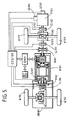
- FIG. 6 shows the fifth application of the system of Figure 1.
- a clutch CL105 is installed between the rear section output middle shaft and the middle transmission device, clutch CL104 is eliminated, and the system functions are delineated in Table 6.
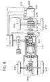
- FIG. 7 shows the sixth application of the system of Figure 1.
- a clutch CL105 is installed between the rear section output middle shaft and the middle transmission device, clutch CL104 and brake B102 are eliminated, and the system functions are delineated in Table 7.
- Figure 8 shows the seventh application of the system of Figure 1. It discloses an application which includes additional clutch CL105 and eliminates clutches CL101, CL104 and brake B102, and the system functions are delineated in Table 8.
- the angular displacement relationships between the front and rear section loads and the drive power source resulting from the transmission ratio and the wheel outside diameter differences may be as follows:
- the angular displacement speed of the two loads and the drive side rotational power source are operated according to the wheel system ratio relationships, or the angular displacement relationship between the two loads and their operations with the drive side rotational power source are not according to the wheel system ratio (such as slipping on the road surface).
- the relationships between the angular displacement of the rear section load and the drive side power source or between the front and rear section loads can be especially set not to operate according to the wheel system ratio relationship, but to operate through the differential acting adjustment by the electromagnetic coupling device;
- the distributed differential coupling combined power system of the invention can be applied to vehicles, boats, or other machinery requiring combined driving power.
- the examples given herein encompass the various applications of the basic distributed differential coupling combined power system concept of the invention and in practical applications, any peripheral components for the output functions can be selected according to need, providing a highly flexible system.
Landscapes
- Engineering & Computer Science (AREA)
- Chemical & Material Sciences (AREA)
- Combustion & Propulsion (AREA)
- Transportation (AREA)
- Mechanical Engineering (AREA)
- Power Engineering (AREA)
- Automation & Control Theory (AREA)
- Electric Propulsion And Braking For Vehicles (AREA)
- Hybrid Electric Vehicles (AREA)
Claims (11)
- Differenziert mischendes, kombiniertes Kraftübertragungssystem für einen Motor, wobei der Motor umfaßt:dadurch gekennzeichnet, daßeine Drehkraftquelle (P101) auf der Antriebsseite mit einer Ausgangsleistung, welche zuerst einer Vorderabschnittlast zugeführt und dann an ein Eingangsende einer elektromagnetischen Kopplungsvorrichtung (M101) zum Antreiben einer Hinterabschnittslast übertragen wird;die Drehkraftquelle (P101) auf der Antriebsseite, welche eine Drehausgangswelle (S102) umfaßt, welche mit einer mittleren Getriebevorrichtung und einer Steuerschnittstelle (M102) verbunden ist;eine zentrale Steuervorrichtung (CCU101) und ein steuerbares Kraftstoffventil (CG101), welches durch die zentrale Steuervorrichtung gesteuert wird;die mittlere Getriebevorrichtung und die Steuerschnittstelle (M102) mit einem Geschwindigkeitsänderungssteuersystem zum Antreiben lediglich der Vorderabschnittslast und ferner zum Antreiben beider Lasten;eine mittlere Eingangswelle (S101);die elektromagnetische Kopplungsvorrichtung (M101), welche mit der mittleren Getriebewelle (S101) zum Antrieben der Hinterabschnittslast verbunden ist;eine zwischen der elektromagnetischen Kopplungsvorrichtung (M101) und einer Batterie (BT101) eingebaute Treiberschaltungsvorrichtung (D101), welche derart angeordnet ist, daß diese Betriebsbefehle von der zentralen Steuervorrichtung (CCU101) empfängt, um die elektromagnetische Kopplungsvorrichtung derart zu steuern, daß diese als Generator zum Laden der Batterie, zum Zuführen von Kraft an jegliche andere damit verbundenen Lasten sowie zum Liefern einer stromsteuerbaren Generatorausgangsleistung, so daß die Drehzahl in Reaktion auf Lastbedingungen geändert wird, wirkt;die Ausgangswelle (S102) der Drehkraftquelle (P101) mit der mittleren Getriebevorrichtung und der Steuerschnittstelle (M102) über eine Kupplung (CL102) verbunden ist;die Drehkraftquelle (P101) ferner einen Geschwindigkeitssensor (SD101) umfaßt; unddie mittlere Getriebevorrichtung und die Steuerschnittstelle eine Geschwindigkeitsänderungssteuervorrichtung zum Antreiben der Vorderabschnittslast und ferner zum Antreiben beider Lasten umfassen.
- System nach Anspruch 1, ferner umfassend eine Bremse (B102), welche zwischen differenziell wirkenden Ausgangswellen der elektromagnetischen Kupplungsvorrichtung (M101) und einem gekoppelten hinteren Differentialgetriebe, über welches die Hinterabschnittslast angetrieben wird, angeordnet ist.
- System nach Anspruch 2, ferner umfassend eine Kupplung (CL104), welche zwischen der Bremse (B102) und der Hinterabschnittslast angeordnet ist.
- System nach einem der Ansprüche 1 bis 3, ferner umfassend eine Kupplung (CL103), welche zwischen der mittleren Eingangswelle (S101) und der Vorderabschnittslast eingebaut ist, so daß eine Getriebekopplung zwischen der mittleren Getriebevorrichtung und der Vorderabschnittslast geliefert wird.
- System nach einem der Ansprüche 1 bis 4, wobei die zentrale Steuervorrichtung eine Einrichtung umfaßt, welche bewirkt, daß das System die folgenden Funktionen ausführt:Steuern des Kraftstoffventils, um den Motor von einer hohen Drehzahl zu einer niedrigen Drehzahl zu steuern;gleichzeitiges Steuern des Kraftstoffventils und der elektromagnetischen Kopplungsvorrichtung, um den Motor von einer niedrigen Drehzahl zu einer hohen Drehzahl anzutreiben und die Batterie gleichzeitig zu laden;Ändern der Motordrehzahl, indem bewirkt wird, daß die elektromagnetische Kopplungsvorrichtung einen Strom zum Steuern eines Ausgangswellendrehmoments erzeugt;Bewirken, daß die elektromagnetische Kopplungsvorrichtung durch die Batterie betrieben wird, so daß eine Drehrichtung der Hinterabschnittslast geändert wird;Betreiben der elektromagnetischen Kopplungsvorrichtung durch die Batterie, so daß eine Geschwindigkeit bzw. Richtung der Vorderabschnittslast geändert wird;Betreiben des Motors bei einer voreingestellten Drehzahl, während die elektromagnetische Kopplungsvorrichtung als Motor betrieben wird, so daß eine zusätzliche Kraft zum Antreiben der Hinterabschnittslast geliefert wird;Betreiben des Motors bei einer voreingestellten Drehzahl, während die elektromagnetische Kopplungsvorrichtung als Motor betrieben wird, so daß eine zusätzliche Kraftausgangsleistung zum Antreiben der Vorderabschnittslast und der Hinterabschnittslast geliefert wird;Betreiben des Motors als Generator zum Laden der Batterie unter Verwendung kinetischer Energie, welche aus der Hinterabschnittslast gewonnen wird;Betrieben der elektromagnetischen Kopplungsvorrichtung als Generator zum Laden der Batterie unter Verwendung kinetischer Energie, welche aus der Vorderabschnittslast gewonnen wird;Bewirken, daß sämtliche Lasten durch eine Reibungsdämpfung des Motors gebremst werden;Bewirken, daß die elektromagnetische Kopplungsvorrichtung durch den Motor derart angetrieben wird, daß diese als Generator zum Laden der Batterie bzw. zum Liefern eines Wechselstromausgangsleistung veränderlicher oder konstanter Frequenz für unterschiedliche Situationen wirkt; undBetreiben der elektromagnetischen Kopplungsvorrichtung als Motor zum Starten des Motors.
- System nach Anspruch 5, wobei die zentrale Steuervorrichtung eine Einrichtung umfaßt, welche bewirkt, daß die elektromagnetische Kopplungsvorrichtung durch den Motor derart angetrieben wird, daß diese als Generator zum Laden der Batterie wirkt und eine Ausgangsleistung einer elektromagnetischen Kopplung an jegliche zusätzlichen damit verbundenen Lasten liefert.
- System nach Anspruch 5 oder 6, wobei die zentrale Steuervorrichtung eine Einrichtung umfaßt, welche den Motor als Generator betreibt, so daß die Batterie unter Verwendung von aus der Vorderabschnittslast gewonnener kinetischer Energie geladen wird.
- System nach einem der Ansprüche 1 bis 7, ferner umfassend eine Kupplung (CL105) zwischen der mittleren Ausgangswelle des hinteren Abschnitts und der mittleren Getriebevorrichtung, wobei die zentrale Steuervorrichtung eine Einrichtung umfaßt, welche den Motor derart betreibt, daß dieser die Vorderabschnittslast antreibt, und welche die elektromagnetische Kopplungsvorrichtung derart unabhängig betreibt, daß diese die Hinterabschnittslast antreibt; und
wobei der Motor derart betrieben wird, daß dieser die Vorderabschnittslast antreibt, wobei bewirkt wird, daß der Motor ferner die elektromagnetische Kopplungsvorrichtung zum Laden der Batterie antreibt. - System nach einem der Ansprüche 1 bis 8, wobei die Vorderabschnittslast und die Hinterabschnittslast Räder sind und Beziehungen zwischen der Vorderabschnittslast und der Hinterabschnittslast derart festgelegt sind, daß diese nicht gemäß der Beziehung des Radsystemverhältnisses, sondern über eine differenziell wirkende Einstellung durch die elektromagnetische Kopplungsvorrichtung (U101) wirken.
- System nach Anspruch 9, wobei die differenziell wirkende Einstellung der elektromagnetischen Kopplungsvorrichtung (U101) eine aktive Einstellung der Eingangskraft, wenn die elektromagnetische Kopplungsvorrichtung als Motor wirkt, und eine passive Einstellung der Ausgangsleistung, wenn die elektromagnetische Kopplungsvorrichtung als Generator wirkt, umfaßt.
- System nach einem der Ansprüche 1 bis 10, wobei die Vorderabschnittslast der vordere bzw. der hintere Rädersatz eines Fahrzeugs und die Hinterabschnittslast der jeweils andere Rädersatz, der hintere bzw. vordere Rädersatz, ist.
Priority Applications (3)
| Application Number | Priority Date | Filing Date | Title |
|---|---|---|---|
| US08/317,633 US5562566A (en) | 1994-10-03 | 1994-10-03 | Distributed differential mixing combined power system |
| DE69611823T DE69611823T2 (de) | 1996-05-09 | 1996-05-09 | Hybridantriebssystem mit elektrischer Kupplung zur differentiellen Antriebskraftverteilung |
| EP96303258A EP0806315B1 (de) | 1994-10-03 | 1996-05-09 | Hybridantriebssystem mit elektrischer Kupplung zur differentiellen Antriebskraftverteilung |
Applications Claiming Priority (3)
| Application Number | Priority Date | Filing Date | Title |
|---|---|---|---|
| US08/317,633 US5562566A (en) | 1994-10-03 | 1994-10-03 | Distributed differential mixing combined power system |
| EP96303258A EP0806315B1 (de) | 1994-10-03 | 1996-05-09 | Hybridantriebssystem mit elektrischer Kupplung zur differentiellen Antriebskraftverteilung |
| AU52195/96A AU727772B2 (en) | 1996-05-09 | 1996-05-10 | Distributed differential coupling combined power system |
Publications (2)
| Publication Number | Publication Date |
|---|---|
| EP0806315A1 EP0806315A1 (de) | 1997-11-12 |
| EP0806315B1 true EP0806315B1 (de) | 2001-02-21 |
Family
ID=27154800
Family Applications (1)
| Application Number | Title | Priority Date | Filing Date |
|---|---|---|---|
| EP96303258A Expired - Lifetime EP0806315B1 (de) | 1994-10-03 | 1996-05-09 | Hybridantriebssystem mit elektrischer Kupplung zur differentiellen Antriebskraftverteilung |
Country Status (2)
| Country | Link |
|---|---|
| US (1) | US5562566A (de) |
| EP (1) | EP0806315B1 (de) |
Cited By (1)
| Publication number | Priority date | Publication date | Assignee | Title |
|---|---|---|---|---|
| WO2015020854A1 (en) * | 2013-08-08 | 2015-02-12 | Hpev, Inc. | Parallel power input gearbox |
Families Citing this family (69)
| Publication number | Priority date | Publication date | Assignee | Title |
|---|---|---|---|---|
| JP3042342B2 (ja) * | 1994-12-28 | 2000-05-15 | 株式会社エクォス・リサーチ | ハイブリッド型車両 |
| JP2783983B2 (ja) * | 1995-02-03 | 1998-08-06 | 株式会社エクォス・リサーチ | ハイブリッド型車両 |
| JP2973920B2 (ja) * | 1995-05-24 | 1999-11-08 | トヨタ自動車株式会社 | ハイブリッド電気自動車 |
| JPH0937410A (ja) * | 1995-07-24 | 1997-02-07 | Toyota Motor Corp | 車両用駆動制御装置 |
| JP3350314B2 (ja) * | 1995-09-29 | 2002-11-25 | 富士重工業株式会社 | ハイブリッド自動車の駆動装置 |
| JP3129204B2 (ja) * | 1995-10-18 | 2001-01-29 | トヨタ自動車株式会社 | ハイブリッド駆動装置 |
| JPH09172705A (ja) * | 1995-12-15 | 1997-06-30 | Denso Corp | 車両用駆動装置 |
| US5713425A (en) * | 1996-01-16 | 1998-02-03 | Ford Global Technologies, Inc. | Parallel hybrid powertrain for an automotive vehicle |
| JPH1023721A (ja) * | 1996-07-02 | 1998-01-23 | Toyota Motor Corp | 動力出力装置 |
| JP3050141B2 (ja) * | 1996-09-24 | 2000-06-12 | トヨタ自動車株式会社 | 動力出力装置およびその制御方法 |
| JP3216589B2 (ja) * | 1996-10-29 | 2001-10-09 | トヨタ自動車株式会社 | 動力出力装置,原動機制御装置並びにこれらの制御方法 |
| US5804935A (en) * | 1997-02-06 | 1998-09-08 | Radev; Vladimir | Drive system for electric vehicles |
| DE69821750T2 (de) | 1997-04-18 | 2006-06-22 | Transport Energy Systems Pty. Ltd., Holland Park | Hybridantriebssystem zur Verwendung im Fahrzeugbetrieb |
| US6019698A (en) * | 1997-12-01 | 2000-02-01 | Daimlerchysler Corporation | Automated manual transmission shift sequence controller |
| US5943918A (en) * | 1997-12-01 | 1999-08-31 | Chrysler Corporation | Powertrain system for a hybrid electric vehicle |
| US6006620A (en) * | 1997-12-01 | 1999-12-28 | Chrysler Corporation | Automated manual transmission controller |
| US6157147A (en) * | 1998-04-20 | 2000-12-05 | Pan-Chien Lin | Power transmission apparatus |
| JP3336951B2 (ja) * | 1998-04-28 | 2002-10-21 | 株式会社日立製作所 | 自動車の動力伝達装置 |
| DE19835575A1 (de) * | 1998-08-06 | 2000-03-02 | Mannesmann Sachs Ag | Parallelhybridantrieb für ein Kraftfahrzeug mit in die elektrische Maschine integrierter Kupplung und zugehörige Elektromotorbaueinheit |
| US6205379B1 (en) * | 1998-09-04 | 2001-03-20 | Toyota Jidosha Kabushiki Kaisha | Controller for hybrid vehicle wherein one and the other of front and rear wheels are respectively driven by engine and electric motor |
| US6554088B2 (en) | 1998-09-14 | 2003-04-29 | Paice Corporation | Hybrid vehicles |
| US6047104A (en) * | 1998-09-22 | 2000-04-04 | Cheng Technology & Services, Inc. | Electrical generators and motors in which at steady-state the rotor and its electromagnetic field rotate at selectively different angular speeds |
| US6392371B1 (en) | 1998-09-22 | 2002-05-21 | Cheng Power Systems, Inc. | Universal frequency electrical generator |
| JP3414310B2 (ja) | 1998-09-25 | 2003-06-09 | トヨタ自動車株式会社 | エンジンの始動制御装置 |
| DE19855790A1 (de) * | 1998-12-03 | 2000-06-15 | Bosch Gmbh Robert | Getriebeaggregat für ein Kraftfahrzeug |
| JP2001146121A (ja) | 1999-11-19 | 2001-05-29 | Toyota Motor Corp | 変速機付きハイブリッド車両の制御装置 |
| WO2002008574A1 (en) * | 2000-07-19 | 2002-01-31 | Daimlerchrysler Ag | Energy conversion system and method for operating the same |
| US6447423B1 (en) | 2000-07-31 | 2002-09-10 | Caterpillar Inc. | Method and apparatus for adjusting transmission ratio commands for a continuously variable transmission |
| US6427797B1 (en) * | 2001-02-07 | 2002-08-06 | Hui-Lung Chang | Transmission structure of gearbox of electrically actuated car |
| EP1244201A1 (de) * | 2001-03-21 | 2002-09-25 | Ford Global Technologies, Inc., A subsidiary of Ford Motor Company | Elekromechanische Kopplungsvorrichtung für die Kraftübertragung im KFZ |
| US6461266B1 (en) | 2001-04-26 | 2002-10-08 | Ervin Weisz | Differential electric engine with variable torque conversion |
| US6541940B1 (en) | 2001-12-19 | 2003-04-01 | Abb Research Ltd. | Load follower using batteries exhibiting memory |
| US6638195B2 (en) * | 2002-02-27 | 2003-10-28 | New Venture Gear, Inc. | Hybrid vehicle system |
| US7102245B2 (en) | 2002-03-21 | 2006-09-05 | Torque-Traction Technologies Llc | Integral generator/pinion assembly for axle power generation |
| US20050205313A1 (en) * | 2004-03-19 | 2005-09-22 | Gilmore Curt D | Hybrid vehicle with power assisted prop shaft |
| US7105937B2 (en) * | 2004-07-14 | 2006-09-12 | Hamilton Sundstrand Corporation | Adjustable variable frequency starter/generator system |
| TWI330218B (en) * | 2004-10-29 | 2010-09-11 | Tai Her Yang | Split serial-parallel hybrid dual-power drive system |
| JP2006176022A (ja) * | 2004-12-22 | 2006-07-06 | Fuji Heavy Ind Ltd | 四輪駆動車の動力伝達装置 |
| US7607505B2 (en) * | 2005-08-12 | 2009-10-27 | Tai-Her Yang | Energy storage type of differential mixed power distribution system |
| GB0603452D0 (en) * | 2006-02-22 | 2006-04-05 | Ford Global Tech Llc | Hybrid motor vehicle driveline |
| CN101177119A (zh) * | 2006-11-08 | 2008-05-14 | 杨泰和 | 储能式双动耦合动力分配装置及系统 |
| FR2911565B1 (fr) * | 2007-01-19 | 2009-02-27 | Renault Sas | Systeme et procede de commande d'un groupe motopropulseur hybride pour un fonctionnement en mode quatre roues motrices permanent |
| DE102007031605A1 (de) * | 2007-07-06 | 2009-01-22 | Dr. Ing. H.C. F. Porsche Aktiengesellschaft | Hybridfahrzeug |
| US7669683B2 (en) * | 2007-12-04 | 2010-03-02 | Tai-Her Yang | Energy storage type of dual-drive coupled power distribution system |
| US7726430B2 (en) * | 2007-12-04 | 2010-06-01 | Tai-Her Yang | Energy storage type of differential hybrid power distribution system |
| US8042642B2 (en) * | 2008-08-14 | 2011-10-25 | American Axle & Manufacturing, Inc. | Motor vehicle with disconnectable all-wheel drive system |
| US8047323B2 (en) * | 2008-08-14 | 2011-11-01 | American Axle & Manufacturing, Inc. | Motor vehicle with disconnectable all-wheel drive system |
| US8169115B1 (en) * | 2008-09-26 | 2012-05-01 | Edward Riggs Monfort | Motor distributor system |
| US8083016B2 (en) * | 2009-04-13 | 2011-12-27 | GM Global Technology Operations LLC | Vehicle with hybrid powertrain |
| GB2486632B (en) * | 2010-12-06 | 2014-04-02 | Protean Electric Ltd | An electric hybrid vehicle |
| US8523738B2 (en) * | 2011-01-21 | 2013-09-03 | Dana Heavy Vehicle Systems Group, Llc | Method of shifting a tandem drive axle having an inter-axle differential |
| WO2012145350A1 (en) | 2011-04-18 | 2012-10-26 | GKN Driveline Newton, LLC | Power transfer unit |
| CN103596794B (zh) | 2011-04-20 | 2017-08-25 | Gkn 动力传动系统有限责任公司 | 动力传输单元 |
| DE102011007874A1 (de) * | 2011-04-21 | 2012-10-25 | Bayerische Motoren Werke Aktiengesellschaft | Vorrichtung und Verfahren zum Starten eines in einem Fahrzeug angeordneten Verbrennungsmotors |
| US8961353B2 (en) | 2012-05-14 | 2015-02-24 | American Axle & Manufacturing, Inc. | Two-speed disconnecting driveline with one reduction gearset |
| US8784254B2 (en) | 2012-05-14 | 2014-07-22 | American Axle & Manufacturing, Inc. | Power transmitting component |
| US8795126B2 (en) | 2012-05-14 | 2014-08-05 | American Axle & Manufacturing, Inc. | Disconnectable driveline for all-wheel drive vehicle |
| US8469854B1 (en) | 2012-05-15 | 2013-06-25 | American Axle & Manufacturing, Inc. | Disconnectable driveline for all-wheel drive vehicle |
| WO2013188647A1 (en) | 2012-06-15 | 2013-12-19 | American Axle & Manufacturing, Inc. | Disconnectable driveline with a multi-speed rdm and ptu |
| WO2014055733A1 (en) | 2012-10-05 | 2014-04-10 | American Axle & Manufacturing, Inc. | Single speed and two-speed disconnecting axle arrangements |
| DE102014202103B4 (de) * | 2014-02-05 | 2023-11-16 | Bayerische Motoren Werke Aktiengesellschaft | Verfahren und Steuervorrichtung zum Betrieb eines straßengekoppelten Hybridfahrzeuges |
| CN104648172B (zh) * | 2015-02-03 | 2016-11-30 | 刘岩 | 油电混合转换变速装置及油电混合转换变速装置的控制方法 |
| JP6187529B2 (ja) * | 2015-04-16 | 2017-08-30 | トヨタ自動車株式会社 | 4輪駆動車両 |
| JP6914247B2 (ja) * | 2015-05-01 | 2021-08-04 | ブラックバーン エナジー インコーポレイテッド | 補助発電のための方法およびシステム |
| JP6327267B2 (ja) * | 2016-03-04 | 2018-05-23 | トヨタ自動車株式会社 | 車両の制御装置 |
| DE102017212545A1 (de) * | 2017-07-21 | 2019-01-24 | Ford Global Technologies, Llc | Aufhängungssystem |
| US10704663B2 (en) | 2018-09-06 | 2020-07-07 | American Axle & Manufacturing, Inc. | Modular disconnecting drive module with torque vectoring augmentation |
| US10927937B2 (en) | 2018-09-06 | 2021-02-23 | American Axle & Manufacturing, Inc. | Modular disconnecting drive module with torque vectoring augmentation |
| CN115549402A (zh) * | 2022-10-21 | 2022-12-30 | 松果新能源汽车有限公司 | 一种新能源汽车一体化电机动力驱动系统 |
Family Cites Families (8)
| Publication number | Priority date | Publication date | Assignee | Title |
|---|---|---|---|---|
| US4309620A (en) * | 1979-12-03 | 1982-01-05 | Calspan Corporation | Flywheel electric transmission apparatus |
| US4405029A (en) * | 1980-01-02 | 1983-09-20 | Hunt Hugh S | Hybrid vehicles |
| US4319140A (en) * | 1980-07-28 | 1982-03-09 | Paschke Ralph W | Demand operated power management drive system |
| US5120282A (en) * | 1990-10-16 | 1992-06-09 | Fjaellstroem Bengt | Vehicle transmission system |
| ATA6192A (de) * | 1992-01-16 | 1997-05-15 | Avl Verbrennungskraft Messtech | Antriebsvorrichtung antriebsvorrichtung |
| US5327987A (en) * | 1992-04-02 | 1994-07-12 | Abdelmalek Fawzy T | High efficiency hybrid car with gasoline engine, and electric battery powered motor |
| US5301764A (en) * | 1992-04-13 | 1994-04-12 | Gardner Conrad O | Hybrid motor vehicle having an electric motor and utilizing an internal combustion engine for fast charge during cruise mode off condition |
| GB2275309B (en) * | 1993-02-22 | 1997-10-29 | Yang Tai Her | Differential coupling and compounding system |
-
1994
- 1994-10-03 US US08/317,633 patent/US5562566A/en not_active Ceased
-
1996
- 1996-05-09 EP EP96303258A patent/EP0806315B1/de not_active Expired - Lifetime
Cited By (1)
| Publication number | Priority date | Publication date | Assignee | Title |
|---|---|---|---|---|
| WO2015020854A1 (en) * | 2013-08-08 | 2015-02-12 | Hpev, Inc. | Parallel power input gearbox |
Also Published As
| Publication number | Publication date |
|---|---|
| EP0806315A1 (de) | 1997-11-12 |
| US5562566A (en) | 1996-10-08 |
Similar Documents
| Publication | Publication Date | Title |
|---|---|---|
| EP0806315B1 (de) | Hybridantriebssystem mit elektrischer Kupplung zur differentiellen Antriebskraftverteilung | |
| US5547433A (en) | Distributed differential coupling combined power system | |
| USRE37743E1 (en) | Distributed differential mixing combined power system | |
| CN1572052B (zh) | 电力机械转换器 | |
| US6020697A (en) | Hybrid vehicle | |
| JP2015157628A (ja) | 二次エネルギ源のための動力の伝達にパワーテイクオフ接続を用いる並列ハイブリッドドライブシステム | |
| JP2010533100A5 (de) | ||
| US20140121867A1 (en) | Method of controlling a hybrid powertrain with multiple electric motors to reduce electrical power losses and hybrid powertrain configured for same | |
| GB2278242A (en) | Electromagnetic transmission system including variable-speed electric motor | |
| CN1166417A (zh) | 分配式差动耦合复合动力系统 | |
| EP0826544B1 (de) | Kombiniertes Antriebssystem mit Kraftmaschine und elektrischer Maschine | |
| JP2000278809A (ja) | ハイブリッド車の駆動機構 | |
| CN103072459A (zh) | 变速器、混合动力系统和混合动力汽车 | |
| RU2126507C1 (ru) | Установка с комбинированным приводом и дифференциальным соединением (варианты) | |
| US9096119B2 (en) | Vehicle drive system and use of an electromechanical converter | |
| EP1642759B1 (de) | Elektrisches Antriebssystem mit doppelt wirkenden Elektromotoren und Ausgleichsgetriebe | |
| KR100293543B1 (ko) | 하이브리드변속기 | |
| JP3710201B2 (ja) | 異なる組合せの複合動力分配装置 | |
| JP2011508698A (ja) | 補機駆動システム、及び電気機械変換器の使用法 | |
| KR100453859B1 (ko) | 차동결합복합동력분산시스템 | |
| KR100443731B1 (ko) | 다기능복합동력장치 | |
| KR100465084B1 (ko) | 차동혼합복합동력분산시스템 | |
| JP3650473B2 (ja) | 差動混合の複合動力分配装置 | |
| RU2171185C2 (ru) | Комбинированная энергосистема для дифференциального распределения мощности | |
| RU2171752C2 (ru) | Комбинированная система дифференцированного распределения мощности |
Legal Events
| Date | Code | Title | Description |
|---|---|---|---|
| PUAI | Public reference made under article 153(3) epc to a published international application that has entered the european phase |
Free format text: ORIGINAL CODE: 0009012 |
|
| AK | Designated contracting states |
Kind code of ref document: A1 Designated state(s): BE CH DE DK ES FR GB GR IT LI NL SE |
|
| 17P | Request for examination filed |
Effective date: 19980512 |
|
| 17Q | First examination report despatched |
Effective date: 19980720 |
|
| GRAG | Despatch of communication of intention to grant |
Free format text: ORIGINAL CODE: EPIDOS AGRA |
|
| GRAG | Despatch of communication of intention to grant |
Free format text: ORIGINAL CODE: EPIDOS AGRA |
|
| GRAH | Despatch of communication of intention to grant a patent |
Free format text: ORIGINAL CODE: EPIDOS IGRA |
|
| GRAH | Despatch of communication of intention to grant a patent |
Free format text: ORIGINAL CODE: EPIDOS IGRA |
|
| GRAA | (expected) grant |
Free format text: ORIGINAL CODE: 0009210 |
|
| AK | Designated contracting states |
Kind code of ref document: B1 Designated state(s): BE CH DE DK ES FR GB GR IT LI NL SE |
|
| PG25 | Lapsed in a contracting state [announced via postgrant information from national office to epo] |
Ref country code: SE Free format text: THE PATENT HAS BEEN ANNULLED BY A DECISION OF A NATIONAL AUTHORITY Effective date: 20010221 Ref country code: NL Free format text: LAPSE BECAUSE OF FAILURE TO SUBMIT A TRANSLATION OF THE DESCRIPTION OR TO PAY THE FEE WITHIN THE PRESCRIBED TIME-LIMIT Effective date: 20010221 Ref country code: LI Free format text: LAPSE BECAUSE OF FAILURE TO SUBMIT A TRANSLATION OF THE DESCRIPTION OR TO PAY THE FEE WITHIN THE PRESCRIBED TIME-LIMIT Effective date: 20010221 Ref country code: ES Free format text: THE PATENT HAS BEEN ANNULLED BY A DECISION OF A NATIONAL AUTHORITY Effective date: 20010221 Ref country code: CH Free format text: LAPSE BECAUSE OF FAILURE TO SUBMIT A TRANSLATION OF THE DESCRIPTION OR TO PAY THE FEE WITHIN THE PRESCRIBED TIME-LIMIT Effective date: 20010221 Ref country code: BE Free format text: LAPSE BECAUSE OF FAILURE TO SUBMIT A TRANSLATION OF THE DESCRIPTION OR TO PAY THE FEE WITHIN THE PRESCRIBED TIME-LIMIT Effective date: 20010221 |
|
| REG | Reference to a national code |
Ref country code: CH Ref legal event code: EP |
|
| REF | Corresponds to: |
Ref document number: 69611823 Country of ref document: DE Date of ref document: 20010329 |
|
| ITF | It: translation for a ep patent filed | ||
| PG25 | Lapsed in a contracting state [announced via postgrant information from national office to epo] |
Ref country code: DK Free format text: LAPSE BECAUSE OF FAILURE TO SUBMIT A TRANSLATION OF THE DESCRIPTION OR TO PAY THE FEE WITHIN THE PRESCRIBED TIME-LIMIT Effective date: 20010521 |
|
| PG25 | Lapsed in a contracting state [announced via postgrant information from national office to epo] |
Ref country code: GR Free format text: LAPSE BECAUSE OF FAILURE TO SUBMIT A TRANSLATION OF THE DESCRIPTION OR TO PAY THE FEE WITHIN THE PRESCRIBED TIME-LIMIT Effective date: 20010525 |
|
| ET | Fr: translation filed | ||
| NLV1 | Nl: lapsed or annulled due to failure to fulfill the requirements of art. 29p and 29m of the patents act | ||
| REG | Reference to a national code |
Ref country code: CH Ref legal event code: PL |
|
| PLBE | No opposition filed within time limit |
Free format text: ORIGINAL CODE: 0009261 |
|
| STAA | Information on the status of an ep patent application or granted ep patent |
Free format text: STATUS: NO OPPOSITION FILED WITHIN TIME LIMIT |
|
| REG | Reference to a national code |
Ref country code: GB Ref legal event code: IF02 |
|
| 26N | No opposition filed | ||
| PGFP | Annual fee paid to national office [announced via postgrant information from national office to epo] |
Ref country code: GB Payment date: 20120529 Year of fee payment: 17 Ref country code: FR Payment date: 20120625 Year of fee payment: 17 |
|
| PGFP | Annual fee paid to national office [announced via postgrant information from national office to epo] |
Ref country code: IT Payment date: 20120531 Year of fee payment: 17 |
|
| PGFP | Annual fee paid to national office [announced via postgrant information from national office to epo] |
Ref country code: DE Payment date: 20130530 Year of fee payment: 18 |
|
| GBPC | Gb: european patent ceased through non-payment of renewal fee |
Effective date: 20130509 |
|
| PG25 | Lapsed in a contracting state [announced via postgrant information from national office to epo] |
Ref country code: IT Free format text: LAPSE BECAUSE OF NON-PAYMENT OF DUE FEES Effective date: 20130509 |
|
| REG | Reference to a national code |
Ref country code: FR Ref legal event code: ST Effective date: 20140131 |
|
| PG25 | Lapsed in a contracting state [announced via postgrant information from national office to epo] |
Ref country code: GB Free format text: LAPSE BECAUSE OF NON-PAYMENT OF DUE FEES Effective date: 20130509 |
|
| PG25 | Lapsed in a contracting state [announced via postgrant information from national office to epo] |
Ref country code: FR Free format text: LAPSE BECAUSE OF NON-PAYMENT OF DUE FEES Effective date: 20130531 |
|
| REG | Reference to a national code |
Ref country code: DE Ref legal event code: R119 Ref document number: 69611823 Country of ref document: DE |
|
| REG | Reference to a national code |
Ref country code: DE Ref legal event code: R079 Ref document number: 69611823 Country of ref document: DE Free format text: PREVIOUS MAIN CLASS: B60K0006040000 Ipc: B60K0006000000 |
|
| REG | Reference to a national code |
Ref country code: DE Ref legal event code: R119 Ref document number: 69611823 Country of ref document: DE Effective date: 20141202 Ref country code: DE Ref legal event code: R079 Ref document number: 69611823 Country of ref document: DE Free format text: PREVIOUS MAIN CLASS: B60K0006040000 Ipc: B60K0006000000 Effective date: 20150121 |
|
| PG25 | Lapsed in a contracting state [announced via postgrant information from national office to epo] |
Ref country code: DE Free format text: LAPSE BECAUSE OF NON-PAYMENT OF DUE FEES Effective date: 20141202 |