EP0806288A1 - Presse, notamment pour le pressage de pièces planes - Google Patents
Presse, notamment pour le pressage de pièces planes Download PDFInfo
- Publication number
- EP0806288A1 EP0806288A1 EP96107097A EP96107097A EP0806288A1 EP 0806288 A1 EP0806288 A1 EP 0806288A1 EP 96107097 A EP96107097 A EP 96107097A EP 96107097 A EP96107097 A EP 96107097A EP 0806288 A1 EP0806288 A1 EP 0806288A1
- Authority
- EP
- European Patent Office
- Prior art keywords
- press according
- press
- tables
- designed
- pressure chamber
- Prior art date
- Legal status (The legal status is an assumption and is not a legal conclusion. Google has not performed a legal analysis and makes no representation as to the accuracy of the status listed.)
- Granted
Links
- 230000008878 coupling Effects 0.000 claims abstract description 6
- 238000010168 coupling process Methods 0.000 claims abstract description 6
- 238000005859 coupling reaction Methods 0.000 claims abstract description 6
- 238000003825 pressing Methods 0.000 claims description 10
- 238000007639 printing Methods 0.000 claims description 7
- 230000003014 reinforcing effect Effects 0.000 claims description 5
- 230000000295 complement effect Effects 0.000 claims description 4
- 230000000149 penetrating effect Effects 0.000 claims description 4
- 230000008921 facial expression Effects 0.000 claims description 3
- 230000002787 reinforcement Effects 0.000 abstract description 3
- 238000013461 design Methods 0.000 description 17
- 239000000463 material Substances 0.000 description 10
- 238000013517 stratification Methods 0.000 description 5
- 238000000034 method Methods 0.000 description 4
- 229910000831 Steel Inorganic materials 0.000 description 3
- 230000005540 biological transmission Effects 0.000 description 3
- 238000004519 manufacturing process Methods 0.000 description 3
- 238000009420 retrofitting Methods 0.000 description 3
- 239000010959 steel Substances 0.000 description 3
- 238000010276 construction Methods 0.000 description 2
- 238000006073 displacement reaction Methods 0.000 description 2
- 230000002093 peripheral effect Effects 0.000 description 2
- 238000012545 processing Methods 0.000 description 2
- 206010010904 Convulsion Diseases 0.000 description 1
- 230000002349 favourable effect Effects 0.000 description 1
- 239000012530 fluid Substances 0.000 description 1
- 238000009434 installation Methods 0.000 description 1
- 238000012986 modification Methods 0.000 description 1
- 230000004048 modification Effects 0.000 description 1
- 238000007645 offset printing Methods 0.000 description 1
Images


Classifications
-
- B—PERFORMING OPERATIONS; TRANSPORTING
- B30—PRESSES
- B30B—PRESSES IN GENERAL
- B30B15/00—Details of, or accessories for, presses; Auxiliary measures in connection with pressing
- B30B15/06—Platens or press rams
- B30B15/062—Press plates
-
- B—PERFORMING OPERATIONS; TRANSPORTING
- B27—WORKING OR PRESERVING WOOD OR SIMILAR MATERIAL; NAILING OR STAPLING MACHINES IN GENERAL
- B27D—WORKING VENEER OR PLYWOOD
- B27D3/00—Veneer presses; Press plates; Plywood presses
- B27D3/02—Veneer presses; Press plates; Plywood presses with a plurality of press plates, i.e. multi- platen hot presses
-
- B—PERFORMING OPERATIONS; TRANSPORTING
- B30—PRESSES
- B30B—PRESSES IN GENERAL
- B30B7/00—Presses characterised by a particular arrangement of the pressing members
- B30B7/02—Presses characterised by a particular arrangement of the pressing members having several platens arranged one above the other
Definitions
- the invention relates to a press, in particular for pressing plate-shaped workpieces with the features of the preamble of patent claim 1.
- Presses with a pressure chamber are known, in particular for pressing plate-shaped workpieces.
- presses with a fixed press table which have a pressure chamber on both sides, i.e. a pressure chamber delimited by the fixed press table and a movable lifting table arranged above and below.
- these pressure chambers can be opened and closed independently of one another, so that these pressure chambers can be fed with pressed material independently of one another in order to be able to process the pressed material independently of the second pressure chamber.
- the conventional presses offer, on the one hand, the possibility of arranging different, described presses next to one another or in series with only one pressure chamber, this being associated with a considerable economic disadvantage, i.e. it requires an immense amount of space and the associated high costs, both in terms of the space required and the transport routes that result.
- Another solution is a so-called multi-daylight press, which should offer the possibility of opening individual pressure rooms independently of one another.
- presses are known in which a lifting table is arranged between two fixed pressing tables, so that two adjacent pressure spaces can be opened and closed alternately with one another.
- the invention is therefore based on the object of providing a press, in particular for pressing plate-shaped workpieces, which is characterized by a small space requirement with high efficiency and the possibility of stacking, i.e. Stratification of two or more presses on top of each other without requiring a great deal of design effort and this while maintaining the possibility of controlling the individual presses, i.e. Maintaining the individual press advantages and ultimately the possibility of easy disassembly, i.e. the possibility of separating the layered presses again, i.e. a needs-based design.
- the press has a device for coupling to at least one further press to be arranged above and / or below it, it is possible to couple the press by simply coupling or stacking with other presses according to the invention such that the presses in Layering can be arranged on top of one another without the functionality of any of the presses arranged in this way suffering.
- the press according to the invention offers the possibility of increasing the workstation as needed, i.e. There is no need as previously to provide a press designed for the growth of the material to be processed at the planning stage, i.e. to commit themselves at this stage and / or tie up capital unnecessarily.
- the modular workstation can be upgraded piece by piece, i.e. be adjusted as needed.
- the device to be coupled presses is positioned and absorbing shear forces, this ensures a precisely fitting and secure fit of the presses to be stacked or stacked on top of one another in a modular design, without the need for significant or constructively complex retrofitting or retrofitting work.
- the device has at least one opening designed to be pluggable, arranged in at least one table and at least partially penetrating this opening, a press is thereby provided in which the devices for coupling to further presses are designed in such a way that the further presses are very simple with one another but can be connected all the more effectively and at the same time experience forced positioning without the need for a common machine frame, that is to say that every upgrade or disassembly results in a structural modification of the entire system.
- the opening is completely penetrating the table, this enables flexible use of the table in the press, i.e. the table or parts of the table can be used as both a lower and an upper table.
- the device has five openings, this ensures a firm fit on the one hand and an optimal positioning of the presses to be arranged one above the other.
- the openings are at least arranged in the tables delimiting the pressure chamber and the openings are designed as bores and the plug-in means are designed as bolts to be inserted precisely into the bores, then a design is selected which on the one hand enables maximum precision and on the other hand is simple and thus guarantees economic construction.
- the tables are designed in several pieces, and in particular in two pieces, this results in a maximum of flexibility when using the tables, i.e. with a minimum of design effort, a maximum of variety is possible.
- the tables have two table tops to be arranged one above the other and the table tops of a table are designed to complement one another, the table tops facing one another of the tables delimiting the pressure space being of the same design and the table tops facing away from one another of the tables delimiting the pressure space also being of the same design, so this creates the possibility of being able to dispense with the mutually facing table tops of the tables of the presses arranged one above the other, for example with appropriate stratification of several presses, so that, for example, the table tops of the presses, which then adjoin one another and which delimit the pressure chambers arranged one above the other, complement one another without the individual presses merging, i.e. their mode of operation and working possibilities and, moreover, the overall height of those to be stacked is achieved Presses is reduced overall, ie the individual presses according to the invention ensure optimum variability with a minimum overall height.
- this feature also contributes to a high degree of flexibility with regard to the connectivity and also the design of the press according to the invention.
- the table top is hollow and it has reinforcing ribs in its interior, which are in particular honeycomb-shaped, then plates and tables are provided which are characterized by high stability and low weight, so that a press with a relatively low weight is provided becomes. This brings with it considerable constructive and economic advantages both in the manufacture and in the transport, in the installation and ultimately in the event of any stacking of the presses.
- honeycomb-shaped reinforcing ribs are at least partially welded to one another at their mutually contacting webs, this reinforces the individual table tops with the least amount of work.
- the device is provided with pulling and / or guide rods and the pulling and / or Guide rods arranged the lifting table with it in operative engagement, so this enables the lifting table to be guided by the device itself, which means that the pressing pressure is applied, ie the lifting table is moved without tilting, without the need for external, ie additional guides, that is to say, constructive configurations are also selected here , which enable an extremely compact design of the press.
- the devices have a pressure cylinder, the pressure cylinder is in operative engagement with the pull and / or guide rods via piston rods and the pressure cylinder is on or in the fixed table with the piston rod is set pointing away from the lifting table, it is also achieved in that the device for generating a pressing pressure is arranged in a space-saving manner, ie
- a constructive design is chosen which is characterized by a low constructive effort combined with high efficiency and compact construction.
- the side of the lifting table facing the pressure cylinder has an opening which can be accommodated coaxially to the pressure cylinder and if the opening is a hole penetrating at least the table top of the lifting table adjacent to the pressure chamber, this creates the possibility of not arranging the device laterally on the tables have to attach, but rather within the effective range or the lifting range of the lifting table, ie with the smallest space requirement and at the same time high efficiency.
- the area of the second table top forming the table adjoining the bore has a notch, then the necessary freedom of movement for the pulling and / or guide rods within the tables is ensured, ie there is no need to attach the pulling and / or Guide rods outside the tables, so that here too a constructive solution is selected which ensures the compact design of the press according to the invention.
- the bore is provided with a slot which extends over the entire bore height, this ensures that supply lines arranged on the pressure cylinder are not damaged when the lifting table is moved accordingly, i.e. the supply lines can be arranged in the simplest way on the pressure cylinder without the risk of damage.
- the table tops have four bores each for receiving a printing cylinder and the bores of the table tops are offset from the bores of the further table tops forming the table tops, it is thereby achieved that the table tops can be manufactured in series and presses despite the economically favorable manufacturing possibility can be provided with printing cylinders arranged in different positions, in particular with regard to stacking the presses, so that the presses to be stacked one above the other have offset printing cylinders.
- the table top four has notches that allow the pull and / or guide rods to be fastened as well as movability of the pull and / or guide rods along with facial expressions, and if the notches of the table tops are offset from the notches of the other table tops that form the table, this is also done achieved by ensuring that despite near-series or series production of the individual table tops and the associated inexpensive configuration of the press, the necessary freedom of movement of the pull and / or guide rods and the associated facial expressions is ensured, in particular when the pressure cylinder is offset.
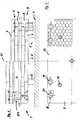
- the press 1 has a pressure space 4 delimited by an upper and lower table 2, 3.
- the lower table 3 is supported by press feet 5 at a distance from the floor 6.
- This lower table 3 is a fixed table, i.e. around a table 3 which remains in position, whereas the upper table 2 is designed as a so-called lifting table, i.e. 1, between an upper open and a lower closed position can be moved by means of hydraulic devices 24 to be described in more detail.
- the tables 2, 3 are designed in two pieces in the present exemplary embodiment, i.e. both the lower and the upper table 2, 3 each have two plates 7, 8.
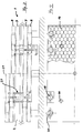
- the individual plates 7, 8 are provided with openings 11 shown in FIG. 2, wherein in the present exemplary embodiment each of the table plates 7, 8, as can be seen from FIGS. 5 and 7, has five openings 11.
- the table tops 7, 8 can be connected to one another with a precise fit by means of a plug connection, these plug connections absorbing transverse forces that occur.
- the individual table tops 7, 8 each consist of an upper and lower cover 12 made of steel, a peripheral frame 13, also made of steel, and between the upper and lower cover 12 and framed by the peripheral frame 13 honeycomb, in here present exemplary embodiment made of steel reinforcement 14.
- the honeycomb reinforcement 14 consists of individual so-called honeycomb rows 15, which are designed in two pieces, i.e. from two complementary honeycomb parts 16, 17, which are welded to one another at their mutually facing and in contact webs 18, as well as on the upper and lower cover 12 of the individual table tops 7, 8.
- the individual table tops 7, 8 have hydraulic cylinder receptacles 19; 20 which are arranged in the table tops 7, 8, the hydraulic cylinder receptacles 19, 20 being a table 2 in the present exemplary embodiment 3 forming plates 7,8 are arranged offset to one another, ie
- the hydraulic cylinder receptacles 19 of the upper and lower table top 7 of the upper and lower table 2, 3 are arranged at a smaller distance from the axis of symmetry 21 than the one in which, respectively, below or Table top 8 of the upper and lower table 2, 3 arranged above.
- the other of the two plates 7, 8 forming a table 2, 3 each have one of the hydraulic cylinder receptacles 19, 20 of the other plate 7.8 opposite opening or notch 22.23.
- the plate 7 opposite the plate 8 which has the hydraulic cylinder receptacle 20 in the corner area is provided with a notch 22 in its corner areas, while the plate 7 which has the hydraulic cylinder receptacle 19 is at a smaller distance from the axis of symmetry 21 7 opposite Plate 8 in the region of the hydraulic cylinder receptacle 19 located above or below it, in the present exemplary embodiment, has openings 23 that are largely rectangular.
- the press feet 5 are designed to be compatible with the hydraulic cylinder receptacles 19; 20, so that the press feet 5 can be positioned in the hydraulic cylinder receptacles 19 present in the lower plate 7, 8 of the lower table 3 or, according to the second exemplary embodiment, hydraulic cylinder receptacles 20 around the press 1 to position or support at a distance from the floor 6.
- the hydraulic devices 24 are in contact with the hydraulic cylinder receptacles 19 arranged at a smaller distance from the axis of symmetry 21, i.e. the hydraulic devices 24 are arranged at a smaller distance from the axis of symmetry 21 than in the exemplary embodiment according to FIGS. 1 and 2 or 9, in which the hydraulic devices 24 are in operative engagement with the hydraulic cylinder receptacles 20 arranged in the corner regions.
- FIGS. 1, 2 and 9 show in detail the arrangement of the hydraulic device 24 in accordance with the first exemplary embodiment according to FIGS. 1, 2 and 9.
- FIG. 11 shows the press 1 with its upper table 2 and lower table 3 in the open state
- FIG. 12 shows the press 1 in the closed state.
- the hydraulic device 24 will be explained in more detail with reference to FIG. 13.
- the upper table 2 consists of an upper plate 7 and a lower table plate 8 and the lower table 3 consists of an upper plate 8 and lower plate 7.
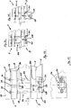
- the press according to the invention has four hydraulic devices 24 which are arranged in the outer edge region of the tables 2, 3, i.e. each press 1 has four hydraulic devices 24.
- the hydraulic devices 24 have a pressure cylinder 25 which, in the viewing direction FIG. 13, below the hydraulic cylinder receptacle 20 of the upper plate 8 of the lower table 3 to the upper plate 8 of the lower table 3, on which the Pressure chamber 4 side is flanged by means of conventional means 26.
- the piston rod 27 points, as can be seen, inter alia, from FIGS. 1, 3, 11, 12 and 13, downward in the direction of view FIG Pressure chamber 4, as can be seen from FIG. 11, in the retracted position and when the pressure chamber 4 is closed, as can be seen from FIG. 12, in the extended state.
- the piston rod 27 At its end facing away from the pressure cylinder 25, the piston rod 27 has a yoke 28, via which two guide rods 29 are coupled to the piston rod 27.
- the guide rods 29 serve at the same time for power transmission or deflection onto the upper table or lifting table 2.
- the guide and power transmission rods 29 are on the lower plate 8 of the upper table 2 on both sides, i.e. both on the top 33 and on the bottom 34 of the lower plate 8 of the upper table so that a vertical displacement of the guide rods 29 inevitably results in a displacement of the upper table 2.
- the pressure chamber 4 With a reverse direction of movement of the piston rod 27, the pressure chamber 4 then opens into the position shown in FIGS. 11 and 13, i.e. for a complete opening of the pressure chamber 4.
- the yoke 27 moves, as shown in Fig. 13, in this position into the area of the lower plate 7 of the lower table 3, i.e. in the area of the notch 22.
- the devices shown in FIG. 13 and used to fix the guide rods 29 on the lower plate 8 of the upper table 2, in the present exemplary embodiment nuts 10, are arranged in the notch 22 of the upper plate 7 of the upper table 2.
- the hydraulic cylinder receptacles 19, 20 are provided with a slot-like opening 36, the width of which is designed such that corresponding Supply lines such as hydraulic fluid connections 37 can be brought through these slots 36 to the pressure cylinder 25 and it is ensured that when the upper table is moved down to the position shown in FIG. 12, the upper hydraulic connection 37, for example, is passed through the slot 36 without it this leads to damage to the connection 37.
- the yoke 28 does not move into the notches 22 of the lower plate 7 of the lower table 3, but rather, according to FIG. 3 and FIG. 10, into the largely rectangular openings 23 of the lower plate 8, the nuts 10 for fixing the Guide rods 29 are arranged in the area of the largely rectangular openings 23 in the upper plate 8 of the upper table 2.
- the design of the press foot 5 is shown in detail by way of example in FIGS. 15, 16, 17 and 18, this foot 5, as can be seen in detail in FIGS. 15, 16, 17, 18, with an upper part 38 in the hydraulic cylinder receptacle 19 , 20 can be arranged and then using conventional means such as to be fixed there by screwing.
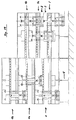
- the press 1 according to the invention corresponding to the first and second exemplary embodiment according to FIGS. 1 and 2 can be arranged one above the other in layers with seizures 1, 1 a, 1 b of the same type or different exemplary embodiments, only in the case of the lower press in the present exemplary embodiment according to FIG 1, which largely correspond to the exemplary embodiment according to FIG. 1, press feet 5 are to be arranged.
- the lower press 1 corresponds to the exemplary embodiment according to FIG. 1 or FIG. 9.
- the second press 1a to be arranged above corresponds to the exemplary embodiment according to FIGS. 3 and 10 and the following one in turn corresponds to the exemplary embodiment according to FIGS. 1 and 9, i.e.
- FIG. 19 it is also possible to arrange a press 1 corresponding to the exemplary embodiment according to FIG. 1 or 9, in the viewing direction FIG. 19, as the lower press 1, with the upper plate 7 of the upper table 2 and in the subsequent second press 1a in accordance with the exemplary embodiment according to FIG. 3 or FIG. 10, the lower plate 7 of the lower table 3 is dispensed with entirely.
- the press 1b is in turn a press 1 according to the first exemplary embodiment according to FIGS. 1 and 9, in which case the lower plate 7 of the lower table 3 can then be dispensed with.
- the upper plate 7, 8 of the lower table 3 of the upper press 1b; 1a thus replaces the upper plate 7; 8 of the upper table 2 of the press 1a; 1 arranged underneath.
- the openings 11 for positioning the plates 7, 8 and absorbing shear forces can be dispensed with entirely.
- the hydraulic devices 24, corresponding to the exemplary embodiment according to FIG. 19 of different presses 1, 1a, 1b are not supplied by a common unit, but rather by separate units, i.e.
- the presses 1,1a, 1b are individual presses 1,1a, 1b which are layered one above the other and which, according to FIG. 19, have only been mechanically coupled to one another, i.e. in order to achieve a defined positioning with respect to one another and to minimize the overall height without this leading to a common control of the individual hydraulic devices 24 or including functioning only in a coupled version.
Landscapes
- Engineering & Computer Science (AREA)
- Mechanical Engineering (AREA)
- Life Sciences & Earth Sciences (AREA)
- Wood Science & Technology (AREA)
- Forests & Forestry (AREA)
- Press Drives And Press Lines (AREA)
Priority Applications (4)
| Application Number | Priority Date | Filing Date | Title |
|---|---|---|---|
| EP96107097A EP0806288B1 (fr) | 1996-05-06 | 1996-05-06 | Presse, notamment pour le pressage de pièces planes |
| DE29622858U DE29622858U1 (de) | 1996-05-06 | 1996-05-06 | Presse, insbesondere zum Verpressen von plattenförmigen Werkstücken |
| AT96107097T ATE200245T1 (de) | 1996-05-06 | 1996-05-06 | Presse, insbesondere zum verpressen von plattenförmigen werkstücken |
| DE59606722T DE59606722D1 (de) | 1996-05-06 | 1996-05-06 | Presse, insbesondere zum Verpressen von plattenförmigen Werkstücken |
Applications Claiming Priority (1)
| Application Number | Priority Date | Filing Date | Title |
|---|---|---|---|
| EP96107097A EP0806288B1 (fr) | 1996-05-06 | 1996-05-06 | Presse, notamment pour le pressage de pièces planes |
Publications (2)
| Publication Number | Publication Date |
|---|---|
| EP0806288A1 true EP0806288A1 (fr) | 1997-11-12 |
| EP0806288B1 EP0806288B1 (fr) | 2001-04-04 |
Family
ID=8222756
Family Applications (1)
| Application Number | Title | Priority Date | Filing Date |
|---|---|---|---|
| EP96107097A Expired - Lifetime EP0806288B1 (fr) | 1996-05-06 | 1996-05-06 | Presse, notamment pour le pressage de pièces planes |
Country Status (3)
| Country | Link |
|---|---|
| EP (1) | EP0806288B1 (fr) |
| AT (1) | ATE200245T1 (fr) |
| DE (2) | DE59606722D1 (fr) |
Citations (7)
| Publication number | Priority date | Publication date | Assignee | Title |
|---|---|---|---|---|
| DE755915C (de) * | 1939-05-27 | 1953-03-02 | Oswald F Wyss Dr | Vorrichtung zum Schliessen oder OEffnen von Mehretagenpressen |
| DE1103002B (de) * | 1959-12-30 | 1961-03-23 | Kralovopolska Strojirna Zd Y C | Presse mit veraenderlicher Pressplatten-anzahl fuer die Herstellung von Sperrholz-, Spanholz- oder Kunststoffplatten |
| DE1182795B (de) * | 1962-10-17 | 1964-12-03 | Becker & Van Huellen | Mehretagenpresse |
| AT290101B (de) * | 1967-05-16 | 1971-05-25 | Becker & Van Huellen | Mehretagen-Presse, insbesondere zur Herstellung von Spanplatten, Faserplatten od.dgl. |
| EP0384958A1 (fr) * | 1989-02-28 | 1990-09-05 | WM WILD MASCHINEN GmbH | Presse à plateaux multiples |
| WO1992022403A1 (fr) * | 1991-06-13 | 1992-12-23 | Herbert Wild | Presse a etages multiples |
| DE9413113U1 (de) * | 1994-08-13 | 1994-10-06 | Wild Förderanlagen GmbH, 33129 Delbrück | Presse mit zumindest zwei übereinanderliegenden Druckräumen |
-
1996
- 1996-05-06 DE DE59606722T patent/DE59606722D1/de not_active Expired - Fee Related
- 1996-05-06 AT AT96107097T patent/ATE200245T1/de not_active IP Right Cessation
- 1996-05-06 DE DE29622858U patent/DE29622858U1/de not_active Expired - Lifetime
- 1996-05-06 EP EP96107097A patent/EP0806288B1/fr not_active Expired - Lifetime
Patent Citations (7)
| Publication number | Priority date | Publication date | Assignee | Title |
|---|---|---|---|---|
| DE755915C (de) * | 1939-05-27 | 1953-03-02 | Oswald F Wyss Dr | Vorrichtung zum Schliessen oder OEffnen von Mehretagenpressen |
| DE1103002B (de) * | 1959-12-30 | 1961-03-23 | Kralovopolska Strojirna Zd Y C | Presse mit veraenderlicher Pressplatten-anzahl fuer die Herstellung von Sperrholz-, Spanholz- oder Kunststoffplatten |
| DE1182795B (de) * | 1962-10-17 | 1964-12-03 | Becker & Van Huellen | Mehretagenpresse |
| AT290101B (de) * | 1967-05-16 | 1971-05-25 | Becker & Van Huellen | Mehretagen-Presse, insbesondere zur Herstellung von Spanplatten, Faserplatten od.dgl. |
| EP0384958A1 (fr) * | 1989-02-28 | 1990-09-05 | WM WILD MASCHINEN GmbH | Presse à plateaux multiples |
| WO1992022403A1 (fr) * | 1991-06-13 | 1992-12-23 | Herbert Wild | Presse a etages multiples |
| DE9413113U1 (de) * | 1994-08-13 | 1994-10-06 | Wild Förderanlagen GmbH, 33129 Delbrück | Presse mit zumindest zwei übereinanderliegenden Druckräumen |
Also Published As
| Publication number | Publication date |
|---|---|
| DE29622858U1 (de) | 1997-07-03 |
| EP0806288B1 (fr) | 2001-04-04 |
| ATE200245T1 (de) | 2001-04-15 |
| DE59606722D1 (de) | 2001-05-10 |
Similar Documents
| Publication | Publication Date | Title |
|---|---|---|
| DE69904861T2 (de) | Zwei-stationen presse für textilmaterial | |
| DE2612206A1 (de) | Heb- und senkbare formlingsbeschickungs- und pressunterlagen-entleerungsvorrichtung fuer eine mehretagenpresse | |
| DE3318314C2 (de) | Vorrichtung zum Trennen einzelner Nutzenstapel eines Stapels gestanzter Bögen | |
| DE7803308U1 (de) | Mechanische einstaenderpresse mit c-foermig ausgebildeter arbeitsstation | |
| DE4119528C2 (fr) | ||
| DE4311154C2 (de) | Einrichtung zur Endbearbeitung eines in einer Tuschierpresse tuschierten Werkzeuges | |
| DE2514515C3 (de) | Presse zum Biegen von Blechen | |
| EP0806288B1 (fr) | Presse, notamment pour le pressage de pièces planes | |
| DE202020101753U1 (de) | Wechselvorrichtung für einen Wechsel von wenigstens zwei Werkstückauflagen für eine Bearbeitungsmaschine | |
| DE3002355C2 (de) | Käsepresse | |
| EP1046482B1 (fr) | Presse à carcasses | |
| EP0638400B1 (fr) | Presse avec au moins deux compartiments de pressage | |
| DE29517428U1 (de) | Packstück-Umreifungsmaschine, insbesondere für eine sich kreuzende Umreifung von Ballen aus einem zusammenpreßbaren Material, wie vor allem Faservlies oder sonstigem Fasermaterial | |
| EP4070943A1 (fr) | Dispositif de presse permettant de presser des pièces en bois, en matière plastique, en métal et similaires | |
| DE8524876U1 (de) | Einrichtung zur Druckbeaufschlagung einer Presse zum Zurichten von Werkzeugen | |
| DE19810574B4 (de) | Vorrichtung zur Betätigung von Pressen in Klemmeinrichtungen für den Zusammenbau von Möbelstücken | |
| EP3024646A1 (fr) | Module de force et système de pressage modulaire | |
| DE2629431C2 (de) | Schlittenständereinheit für Sonderwerkzeugmaschinen | |
| DE4129029A1 (de) | Flachbett-stanzmaschine zum stanzen von flachen gegenstaenden, insbesondere boegen aus papier, pappe oder dergleichen | |
| DE2910536A1 (de) | Ballenpresse, insbesondere fuer faseriges gut | |
| DE3876152T2 (de) | Blechtiefziehvorrichtung. | |
| DE3636226A1 (de) | Holzschleifer | |
| DE2754480C2 (de) | Hydrauliche Hochdruckpresse mit mehreren Pressenrahmen oder Pressengestellen | |
| DE29713214U1 (de) | Schneidmaschine zum Schneiden von Platten | |
| DE2537405A1 (de) | Rahmen fuer pressen, walzwerke und dergleichen maschinen |
Legal Events
| Date | Code | Title | Description |
|---|---|---|---|
| PUAI | Public reference made under article 153(3) epc to a published international application that has entered the european phase |
Free format text: ORIGINAL CODE: 0009012 |
|
| AK | Designated contracting states |
Kind code of ref document: A1 Designated state(s): AT DE DK ES FR GB IT NL PT |
|
| AX | Request for extension of the european patent |
Free format text: LT;LV;SI |
|
| 17P | Request for examination filed |
Effective date: 19971205 |
|
| 17Q | First examination report despatched |
Effective date: 19990622 |
|
| GRAG | Despatch of communication of intention to grant |
Free format text: ORIGINAL CODE: EPIDOS AGRA |
|
| GRAG | Despatch of communication of intention to grant |
Free format text: ORIGINAL CODE: EPIDOS AGRA |
|
| GRAH | Despatch of communication of intention to grant a patent |
Free format text: ORIGINAL CODE: EPIDOS IGRA |
|
| GRAH | Despatch of communication of intention to grant a patent |
Free format text: ORIGINAL CODE: EPIDOS IGRA |
|
| GRAA | (expected) grant |
Free format text: ORIGINAL CODE: 0009210 |
|
| AK | Designated contracting states |
Kind code of ref document: B1 Designated state(s): AT DE DK ES FR GB IT NL PT |
|
| PG25 | Lapsed in a contracting state [announced via postgrant information from national office to epo] |
Ref country code: NL Free format text: LAPSE BECAUSE OF FAILURE TO SUBMIT A TRANSLATION OF THE DESCRIPTION OR TO PAY THE FEE WITHIN THE PRESCRIBED TIME-LIMIT Effective date: 20010404 Ref country code: IT Free format text: LAPSE BECAUSE OF FAILURE TO SUBMIT A TRANSLATION OF THE DESCRIPTION OR TO PAY THE FEE WITHIN THE PRE;WARNING: LAPSES OF ITALIAN PATENTS WITH EFFECTIVE DATE BEFORE 2007 MAY HAVE OCCURRED AT ANY TIME BEFORE 2007. THE CORRECT EFFECTIVE DATE MAY BE DIFFERENT FROM THE ONE RECORDED.SCRIBED TIME-LIMIT Effective date: 20010404 Ref country code: GB Free format text: LAPSE BECAUSE OF FAILURE TO SUBMIT A TRANSLATION OF THE DESCRIPTION OR TO PAY THE FEE WITHIN THE PRESCRIBED TIME-LIMIT Effective date: 20010404 Ref country code: FR Free format text: LAPSE BECAUSE OF FAILURE TO SUBMIT A TRANSLATION OF THE DESCRIPTION OR TO PAY THE FEE WITHIN THE PRESCRIBED TIME-LIMIT Effective date: 20010404 |
|
| REF | Corresponds to: |
Ref document number: 200245 Country of ref document: AT Date of ref document: 20010415 Kind code of ref document: T |
|
| PG25 | Lapsed in a contracting state [announced via postgrant information from national office to epo] |
Ref country code: AT Free format text: LAPSE BECAUSE OF NON-PAYMENT OF DUE FEES Effective date: 20010506 |
|
| REF | Corresponds to: |
Ref document number: 59606722 Country of ref document: DE Date of ref document: 20010510 |
|
| PG25 | Lapsed in a contracting state [announced via postgrant information from national office to epo] |
Ref country code: PT Free format text: LAPSE BECAUSE OF FAILURE TO SUBMIT A TRANSLATION OF THE DESCRIPTION OR TO PAY THE FEE WITHIN THE PRESCRIBED TIME-LIMIT Effective date: 20010704 |
|
| EN | Fr: translation not filed | ||
| NLV1 | Nl: lapsed or annulled due to failure to fulfill the requirements of art. 29p and 29m of the patents act | ||
| GBV | Gb: ep patent (uk) treated as always having been void in accordance with gb section 77(7)/1977 [no translation filed] |
Effective date: 20010404 |
|
| PG25 | Lapsed in a contracting state [announced via postgrant information from national office to epo] |
Ref country code: DK Free format text: LAPSE BECAUSE OF FAILURE TO SUBMIT A TRANSLATION OF THE DESCRIPTION OR TO PAY THE FEE WITHIN THE PRESCRIBED TIME-LIMIT Effective date: 20011012 |
|
| PG25 | Lapsed in a contracting state [announced via postgrant information from national office to epo] |
Ref country code: ES Free format text: LAPSE BECAUSE OF FAILURE TO SUBMIT A TRANSLATION OF THE DESCRIPTION OR TO PAY THE FEE WITHIN THE PRESCRIBED TIME-LIMIT Effective date: 20011030 |
|
| PLBE | No opposition filed within time limit |
Free format text: ORIGINAL CODE: 0009261 |
|
| STAA | Information on the status of an ep patent application or granted ep patent |
Free format text: STATUS: NO OPPOSITION FILED WITHIN TIME LIMIT |
|
| 26N | No opposition filed | ||
| PGFP | Annual fee paid to national office [announced via postgrant information from national office to epo] |
Ref country code: DE Payment date: 20050518 Year of fee payment: 10 |
|
| PG25 | Lapsed in a contracting state [announced via postgrant information from national office to epo] |
Ref country code: DE Free format text: LAPSE BECAUSE OF NON-PAYMENT OF DUE FEES Effective date: 20061201 |