EP0805907B1 - Höhenverstellbares ladenband - Google Patents
Höhenverstellbares ladenband Download PDFInfo
- Publication number
- EP0805907B1 EP0805907B1 EP96900758A EP96900758A EP0805907B1 EP 0805907 B1 EP0805907 B1 EP 0805907B1 EP 96900758 A EP96900758 A EP 96900758A EP 96900758 A EP96900758 A EP 96900758A EP 0805907 B1 EP0805907 B1 EP 0805907B1
- Authority
- EP
- European Patent Office
- Prior art keywords
- hinge
- bushing
- shutter
- hinge plate
- sleeve
- Prior art date
- Legal status (The legal status is an assumption and is not a legal conclusion. Google has not performed a legal analysis and makes no representation as to the accuracy of the status listed.)
- Expired - Lifetime
Links
- 239000011324 bead Substances 0.000 claims description 8
- 229920003023 plastic Polymers 0.000 claims description 4
- 239000004033 plastic Substances 0.000 claims description 4
- 238000010276 construction Methods 0.000 description 3
- 238000006073 displacement reaction Methods 0.000 description 1
- 238000012432 intermediate storage Methods 0.000 description 1
- 230000002427 irreversible effect Effects 0.000 description 1
- 239000002184 metal Substances 0.000 description 1
- 238000003860 storage Methods 0.000 description 1
- 230000007306 turnover Effects 0.000 description 1
Images
Classifications
-
- E—FIXED CONSTRUCTIONS
- E05—LOCKS; KEYS; WINDOW OR DOOR FITTINGS; SAFES
- E05D—HINGES OR SUSPENSION DEVICES FOR DOORS, WINDOWS OR WINGS
- E05D7/00—Hinges or pivots of special construction
- E05D7/0009—Adjustable hinges
- E05D7/0018—Adjustable hinges at the hinge axis
- E05D7/0027—Adjustable hinges at the hinge axis in an axial direction
-
- E—FIXED CONSTRUCTIONS
- E05—LOCKS; KEYS; WINDOW OR DOOR FITTINGS; SAFES
- E05Y—INDEXING SCHEME ASSOCIATED WITH SUBCLASSES E05D AND E05F, RELATING TO CONSTRUCTION ELEMENTS, ELECTRIC CONTROL, POWER SUPPLY, POWER SIGNAL OR TRANSMISSION, USER INTERFACES, MOUNTING OR COUPLING, DETAILS, ACCESSORIES, AUXILIARY OPERATIONS NOT OTHERWISE PROVIDED FOR, APPLICATION THEREOF
- E05Y2900/00—Application of doors, windows, wings or fittings thereof
- E05Y2900/10—Application of doors, windows, wings or fittings thereof for buildings or parts thereof
- E05Y2900/13—Type of wing
- E05Y2900/146—Shutters
-
- E—FIXED CONSTRUCTIONS
- E05—LOCKS; KEYS; WINDOW OR DOOR FITTINGS; SAFES
- E05Y—INDEXING SCHEME ASSOCIATED WITH SUBCLASSES E05D AND E05F, RELATING TO CONSTRUCTION ELEMENTS, ELECTRIC CONTROL, POWER SUPPLY, POWER SIGNAL OR TRANSMISSION, USER INTERFACES, MOUNTING OR COUPLING, DETAILS, ACCESSORIES, AUXILIARY OPERATIONS NOT OTHERWISE PROVIDED FOR, APPLICATION THEREOF
- E05Y2900/00—Application of doors, windows, wings or fittings thereof
- E05Y2900/10—Application of doors, windows, wings or fittings thereof for buildings or parts thereof
- E05Y2900/13—Type of wing
- E05Y2900/148—Windows
Definitions
- the invention relates to a height-adjustable shop belt for Window or door shutters with a mountable on the stock side Hinge pin and a tape hinge on the shop side. If a window or a door shutter due to construction-related assembly tolerances the stock-side band parts its intended position corrective measures must be taken. Modern shop hinge fittings have adjustment devices on, often in the manner of a cross slide with spindles correct adjustment in two or three axis directions enable. Belt parts are loosened, repositioned and tightened again.
- AT-B-324 156 is an adjustable door or Shutter tape with an insert part in a tape sleeve known, which picks up a bearing journal.
- the insert part is in the band sleeve rotatably guided and axially displaceably mounted.
- the shop belt should be structurally simple and compact built and the adjustment simple and with little Exertion of force should be possible, on the other hand it should be irreversible normal, daily operation of the store. Furthermore, the Adjustment when the drawer is suspended, preferably from the room side can be done from. Additional visible construction parts should be avoided so that the loading belt does not gives the impression of a technical machine.
- the unit is intended to be releasably interconnected construction elements contain.
- an adjusting bush is provided coaxially, which in the band sleeve rotatable and axially on the band sleeve, in particular supported on an inner annular surface of the same and that the adjustment bush has an internal thread, on an external thread of the hinge bush for its axial positioning can be screwed on. Opposite the hinge inside the tape sleeve is thus raised or lowered. This is done directly by turning the intermediate storage Adjustment bushing inside the band sleeve.
- the opening for the hinge pin opposite, a cap that can be put on Grips over the edge of the band sleeve and positively in the adjustment bush snaps into place.
- the cap fulfills the function of the cover of the Tape sleeve upwards, especially the tape sleeve for both stop sides can be used.
- the positive locking in the adjusting bush fixes their position as long as the Charging is not yet mounted.
- a special embodiment is characterized in that between the band sleeve and the adjustment bush at the opening for the hinge pin opposite side provided a cylindrical annular gap is in which a cylindrical neck of the cap engages and that the cap on the inner surface of the neck one Ring bead carries in an annular groove of the adjustment bush Forming a releasable snap connection snaps into place.
- the band bushing has a circumference Has nose that in a groove of the band sleeve for non-rotatable Storage intervenes. This causes the hinge bush to rotate with the Band sleeve with, but can be moved in the axial direction. It is particularly advantageous if the groove is for the purpose the left and right-hand mounting option on a shop is provided at both ends of the band sleeve. Thereby can be done by simply turning and repositioning the conveyor belt Band bushing in the band sleeve for left and right hinged Stores are used.
- a specific embodiment is characterized in that that the adjusting bush in its cap area, if necessary recess closed on the bottom for positive locking Connection with an adjustment tool, e.g. a hexagon recess for an Allen key.
- the on the cap on the band sleeve is an opening for reaching through provided for the adjustment tool. Particularly useful it is when the cap or the cylindrical neck of the same carries a nose, which is used for the rotationally fixed positioning of the Cap can be inserted into the groove of the band sleeve.
- the cylindrical Ribbed neck on its cylindrical inner surface is formed and at least one rib on the outer surface the adjustment bush into the ribs to lock the set Rotating position of the adjusting bush engages.
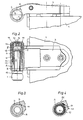
- Fig. 1 shows a store-side tape part with tape sleeve from below, with the hinge and adjustment bushings removed
- Fig. 2 shows a section through the hinge area of the shop belt 1
- Fig. 3 shows a cross section along the line III-III in Fig. 2 without hinge bolts
- Fig. 4 shows a cross section along the line IV-IV in Fig. 2nd
- the shop belt comprises a stock side Band part, namely a support arm 1 projecting from the stick a hinge pin 2 and a shop-side hinge part with a Hinge tab 3 for mounting on a shop 4.
- the hinge tab 3 carries a band sleeve 5, in its cylindrical bore Ring bead 6 is provided with an annular surface 7.
- a band bushing 8 inside the band sleeve 5 Made of friction-reducing plastic, which is axially in the band sleeve 5 displaceable, but against twisting by an in a longitudinal groove 9 engaging nose 10 is secured (Fig. 3).
- a band bushing 8 screwed on from metal, which can be connected to a Collar 13 is supported on the annular surface 7 of the annular bead 6.
- the adjustment bushing 12 has a recess 14 at the top for positive locking Connection with an adjustment tool, here in Shape of a hexagon recess for an Allen key.
- the adjustment bushing 12 If the adjustment bushing 12 is rotated (FIG. 2), then remains it is stationary, but moves in the manner of a spindle gear the band bushing 8. The latter can, depending on the direction of rotation of the Adjustment bushing 12 pushed out of the band sleeve 5 or in these are withdrawn. Because the end face of the hinge bush 8 is supported on a base surface 15 of the hinge pin 2, is by pushing or pulling back the hinge 8 the shop 4 raised or lowered. This is a height adjustment possible in a simple and functional way.
- a cap 16 made of plastic is on the open band sleeve 5 attached.
- a cylindrical neck 17 of the cap 16 engages in a gap between the band sleeve 5 and the adjusting bush 12 and ensures the tight fit of the cap 16, which is characterized by an undercut or annular groove 18 the adjusting sleeve 12 engages annular bead 19.
- the Snap the ring bead 19 into the undercut or ring groove 18 results in a positive connection for pre-fixation the components before mounting the store.
- the individual components as can be seen in the section in Fig. 2 pre-assembled for use as a left or right loading hinge be, the cap 16 snaps on top and the components holds in place.
- the band bushing 8 can be screwed on Adjustment bushing 12 after overcoming the holding force are pulled out of the tape sleeve, the Bead area 19 is elastically deformed.
- the neck 17 is in the area that extends beyond the band sleeve 5 is particularly well elastic deformable. If another bead on the bottom free end of the neck 17, directed outwards, provided is and engages in an annular groove of the band sleeve 5, then the cap 16 can no longer be removed as soon as the adjustment bushing 12 is used because it is an elastic retreat the cylindrical wall of the neck 17 prevented.
- an opening 20 in the cap 16 can be on the recess 14 be acted upon.
- This groove 22 is symmetrical arranged to groove 9 and allows the entire Turn over the store tape and the tape sleeve 8 with the adjusting bush 12 on the other side of the tape sleeve 5.
- the nose 10 then comes to rest in the groove 22 and the cap 16 with its projection or nose 21 in the groove 9 is pushed onto the opening of the band sleeve 5.
- the Tape can be used for both stop sides.
Landscapes
- Engineering & Computer Science (AREA)
- Mechanical Engineering (AREA)
- Hinges (AREA)
- Packaging Of Machine Parts And Wound Products (AREA)
- Packages (AREA)
- Packaging Of Annular Or Rod-Shaped Articles, Wearing Apparel, Cassettes, Or The Like (AREA)
- Support Of The Bearing (AREA)
- Orthopedics, Nursing, And Contraception (AREA)
Description
Claims (9)
- Höhenverstellbares Ladenband für Fenster- oder Türläden mit einem stockseitig montierbaren Bandbolzen (2) und einer ladenseitigen Bandhülse (5), dadurch gekennzeichnet, daß zwischen der Bandhülse (5) und einer drehfest gelagerten und teleskopartig ein- und ausschiebbaren Bandbuchse (8), insbesondere aus gleitfähigem Kunststoff, eine Verstellbuchse (12) koaxial vorgesehen ist, die in der Bandhülse (5) drehbar und sich axial an der Bandhülse (5), insbesondere an einer inneren Ringfläche (7) derselben abstützend, gelagert ist und daß die Verstellbuchse (12) ein Innengewinde trägt, das auf ein Außengewinde (11) der Bandbuchse (8) zu deren axialer Positionierung aufschraubbar ist.
- Höhenverstellbares Ladenband nach Anspruch 1, dadurch gekennzeichnet, daß auf die Bandhülse (5), der Öffnung für den Bandbolzen (2) gegenüberliegend, eine Kappe (16) aufsetzbar ist, die den Rand der Bandhülse (5) übergreift und in die Verstellbuchse (12) formschlüssig einrastet.
- Höhenverstellbares Ladenband nach Anspruch 2, dadurch gekennzeichnet, daß zwischen der Bandhülse (5) und der Verstellbuchse (12) an der der Öffnung für den Bandbolzen (2) gegenüberliegenden Seite ein zylindrischer Ringspalt vorgesehen ist, in welchen ein zylindrischer Hals (17) der Kappe (16) eingreift und daß die Kappe (16) an der Innenfläche des Halses (17) einen Ringwulst (19) trägt, der in eine Ringnut (18) der Verstellbuchse (12) zur Bildung einer lösbaren Schnappverbindung einrastet.
- Höhenverstellbares Ladenband nach einem der Ansprüche 1 bis 3, dadurch gekennzeichnet, daß die Bandbuchse (8) an ihrem Umfang eine Nase (10) aufweist, die in eine Nut (9) der Bandhülse (5) zur drehfesten Lagerung eingreift.
- Höhenverstellbares Ladenband nach Anspruch 4, dadurch gekennzeichnet, daß die Nut (9, 22) zum Zwecke der links- und rechtsseitigen Montagemöglichkeit an einen Laden (4) an beiden Enden der Bandhülse (5) vorgesehen ist.
- Höhenverstellbares Landenband nach einem der Ansprüche 1 bis 5, dadurch gekennzeichnet, daß die Verstellbuchse (12) in ihrem Kappenbereich eine gegebenenfalls bodenseitig geschlossene Ausnehmung (14) zur formschlüssigen Verbindung mit einem Verstellwerkzeug, z.B. eine Sechskantausnehmung für einen Inbusschlüssel, aufweist.
- Höhenverstellbares Ladenband nach Anspruch 6, dadurch gekennzeichnet, daß die Kappe (16) eine Öffnung (20) zum Durchgreifen für ein Verstellwerkzeug aufweist.
- Höhenverstellbares Ladenband nach einem der Ansprüche 2 bis 7, dadurch gekennzeichnet, daß die Kappe (16) bzw. der zylindrische Hals (17) eine Nase (21) trägt, die zur drehfesten Positionierung der Kappe (16) in die Nut (22 bzw. 9) der Bandhülse (5) einsetzbar ist.
- Höhenverstellbares Ladenband nach den Ansprüchen 3 bis 8, dadurch gekennzeichnet, daß der zylindrische Hals (17) an seiner zylindrischen Innenfläche gerippt ausgebildet ist und mindestens eine Rippe an der Außenfläche der Verstellbuchse (12) in die Rippen zur Verrastung der eingestellten Drehlage der Verstellbuchse (12) eingreift.
Applications Claiming Priority (3)
| Application Number | Priority Date | Filing Date | Title |
|---|---|---|---|
| AT0014795A AT401668B (de) | 1995-01-27 | 1995-01-27 | Höhenverstellbares ladenband |
| AT147/95 | 1995-01-27 | ||
| PCT/AT1996/000010 WO1996023124A1 (de) | 1995-01-27 | 1996-01-26 | Höhenverstellbares ladenband |
Publications (2)
| Publication Number | Publication Date |
|---|---|
| EP0805907A1 EP0805907A1 (de) | 1997-11-12 |
| EP0805907B1 true EP0805907B1 (de) | 1998-08-12 |
Family
ID=3482783
Family Applications (1)
| Application Number | Title | Priority Date | Filing Date |
|---|---|---|---|
| EP96900758A Expired - Lifetime EP0805907B1 (de) | 1995-01-27 | 1996-01-26 | Höhenverstellbares ladenband |
Country Status (8)
| Country | Link |
|---|---|
| EP (1) | EP0805907B1 (de) |
| AT (2) | AT401668B (de) |
| DE (1) | DE59600428D1 (de) |
| ES (1) | ES2124080T3 (de) |
| HU (1) | HU222420B1 (de) |
| SI (1) | SI9620020A (de) |
| TR (1) | TR199700684T1 (de) |
| WO (1) | WO1996023124A1 (de) |
Cited By (1)
| Publication number | Priority date | Publication date | Assignee | Title |
|---|---|---|---|---|
| CN110107178A (zh) * | 2019-04-22 | 2019-08-09 | 周芮竹 | 一种旋转门平移装置 |
Families Citing this family (9)
| Publication number | Priority date | Publication date | Assignee | Title |
|---|---|---|---|---|
| DE29614104U1 (de) * | 1996-08-14 | 1997-12-18 | Dr. Hahn GmbH & Co. KG., 41189 Mönchengladbach | Band für Türen, Fenster u.dgl. und dafür geeignete Abdeckung |
| DE29713254U1 (de) * | 1997-07-25 | 1998-11-26 | Niemann, Hans Dieter, 50169 Kerpen | Drehlager für Fenster oder Türen |
| DE29721078U1 (de) * | 1997-11-28 | 1999-04-01 | Niemann, Hans Dieter, 50169 Kerpen | Tür- oder Fensterband |
| DE29804967U1 (de) | 1998-03-20 | 1999-07-22 | Niemann | Tür- oder Fensterband |
| DE19834023B4 (de) * | 1998-07-28 | 2007-11-15 | Siegenia-Aubi Kg | Scharnierteil mit Abdeckkappe |
| DE29919309U1 (de) * | 1999-11-03 | 2001-03-15 | Dr. Hahn GmbH & Co. KG, 41189 Mönchengladbach | Band für Türen, Fenster u.dgl. |
| DE10247296C1 (de) * | 2002-10-10 | 2003-11-06 | Siegfried Felgentreu | Aushebescharnierband |
| FR2921683B1 (fr) * | 2007-09-28 | 2012-08-24 | Tordo Belgrano Sa | Dispositif de montage d'une patte d'articulation pour vantail sur un gond. |
| CN112112501B (zh) * | 2020-10-15 | 2025-01-28 | 春光五金有限公司 | 具有可视化调节的上悬隐藏式铰链结构 |
Family Cites Families (5)
| Publication number | Priority date | Publication date | Assignee | Title |
|---|---|---|---|---|
| US2588258A (en) * | 1949-04-04 | 1952-03-04 | Theodore A Lowman | Adjustable door hinge |
| DE1708860A1 (de) * | 1964-06-20 | 1971-05-13 | Paul Zahn | Anschweissband fuer Tueren,Fenster od. dgl. |
| US3511300A (en) * | 1968-11-12 | 1970-05-12 | John W Matyas | Folding door construction |
| AT324156B (de) * | 1972-10-12 | 1975-08-25 | Stelzer Erich | Tür- oder fensterband |
| DE4339396C1 (de) * | 1993-11-18 | 1995-04-27 | Sfs Sassba Spa | Tür- oder Fensterband |
-
1995
- 1995-01-27 AT AT0014795A patent/AT401668B/de not_active IP Right Cessation
-
1996
- 1996-01-26 AT AT96900758T patent/ATE169713T1/de active
- 1996-01-26 SI SI9620020A patent/SI9620020A/sl not_active IP Right Cessation
- 1996-01-26 DE DE59600428T patent/DE59600428D1/de not_active Expired - Lifetime
- 1996-01-26 WO PCT/AT1996/000010 patent/WO1996023124A1/de not_active Ceased
- 1996-01-26 HU HU9800222A patent/HU222420B1/hu not_active IP Right Cessation
- 1996-01-26 EP EP96900758A patent/EP0805907B1/de not_active Expired - Lifetime
- 1996-01-26 TR TR97/00684T patent/TR199700684T1/xx unknown
- 1996-01-26 ES ES96900758T patent/ES2124080T3/es not_active Expired - Lifetime
Cited By (1)
| Publication number | Priority date | Publication date | Assignee | Title |
|---|---|---|---|---|
| CN110107178A (zh) * | 2019-04-22 | 2019-08-09 | 周芮竹 | 一种旋转门平移装置 |
Also Published As
| Publication number | Publication date |
|---|---|
| AT401668B (de) | 1996-11-25 |
| SI9620020A (en) | 1997-12-31 |
| WO1996023124A1 (de) | 1996-08-01 |
| ATE169713T1 (de) | 1998-08-15 |
| ATA14795A (de) | 1996-03-15 |
| HU222420B1 (hu) | 2003-07-28 |
| HUP9800222A3 (en) | 1999-03-29 |
| DE59600428D1 (de) | 1998-09-17 |
| EP0805907A1 (de) | 1997-11-12 |
| ES2124080T3 (es) | 1999-01-16 |
| HUP9800222A2 (hu) | 1998-05-28 |
| TR199700684T1 (xx) | 1998-02-21 |
Similar Documents
| Publication | Publication Date | Title |
|---|---|---|
| DE3310342C2 (de) | ||
| EP3068963B1 (de) | Scharnier, insbesondere für ein möbelstück | |
| EP1921246B1 (de) | Anschlageinrichtung für die Öffnungs- und Schließbewegung einer Verschattungsanlage | |
| DE2049743B2 (de) | Tuerverschluss | |
| WO1993025790A1 (de) | Scharnier | |
| EP0805907B1 (de) | Höhenverstellbares ladenband | |
| EP1606485B1 (de) | Beschlag | |
| DE3125458A1 (de) | Drehscharnier | |
| EP1235967B1 (de) | Band für türen, fenster oder dergleichen | |
| DE102010047774B4 (de) | Türscharnier | |
| EP1173649B1 (de) | Band für türen, fenster und dergleichen | |
| EP2503084B1 (de) | Verstellbares Scharnierband | |
| EP3045634B1 (de) | Ausstellvorrichtung für ein fenster oder eine tür mit einer energiespeichereinrichtung | |
| EP1400646B1 (de) | Verdeckt liegendes Tür- oder Fensterband | |
| WO2007137644A1 (de) | Band mit verbesserter bandbolzenfixierung | |
| DE19723401C1 (de) | Aushängbares Türscharnier | |
| EP1602794B1 (de) | Rahmenband | |
| DE3344514C2 (de) | ||
| DE20105545U1 (de) | Band für Türen, Fenster o.dgl. | |
| DE102022204028B3 (de) | Scharnierband für eine Gebäudetür oder ein Gebäudefenster | |
| DE20203942U1 (de) | Verbesserte Halterung für Gasstangen | |
| DE29804967U1 (de) | Tür- oder Fensterband | |
| EP3633126A1 (de) | Deckelbeschlag zum schwenkbaren befestigen eines deckels an einen möbelkorpus und möbel mit einem solchen deckelbeschlag | |
| EP1979567A1 (de) | Bandanordnung zur scharniergelenkigen verbindung eines flügels einer tür, eines fensters oder dergleichen, an einem rahmen | |
| DE20108249U1 (de) | Beschlagvorrichtung für eine Möbelklappe |
Legal Events
| Date | Code | Title | Description |
|---|---|---|---|
| PUAI | Public reference made under article 153(3) epc to a published international application that has entered the european phase |
Free format text: ORIGINAL CODE: 0009012 |
|
| 17P | Request for examination filed |
Effective date: 19970707 |
|
| AK | Designated contracting states |
Kind code of ref document: A1 Designated state(s): AT DE ES FR GR IT |
|
| GRAG | Despatch of communication of intention to grant |
Free format text: ORIGINAL CODE: EPIDOS AGRA |
|
| 17Q | First examination report despatched |
Effective date: 19971202 |
|
| GRAG | Despatch of communication of intention to grant |
Free format text: ORIGINAL CODE: EPIDOS AGRA |
|
| GRAH | Despatch of communication of intention to grant a patent |
Free format text: ORIGINAL CODE: EPIDOS IGRA |
|
| GRAH | Despatch of communication of intention to grant a patent |
Free format text: ORIGINAL CODE: EPIDOS IGRA |
|
| GRAA | (expected) grant |
Free format text: ORIGINAL CODE: 0009210 |
|
| AK | Designated contracting states |
Kind code of ref document: B1 Designated state(s): AT DE ES FR GR IT |
|
| REF | Corresponds to: |
Ref document number: 169713 Country of ref document: AT Date of ref document: 19980815 Kind code of ref document: T |
|
| REF | Corresponds to: |
Ref document number: 59600428 Country of ref document: DE Date of ref document: 19980917 |
|
| ET | Fr: translation filed | ||
| REG | Reference to a national code |
Ref country code: ES Ref legal event code: FG2A Ref document number: 2124080 Country of ref document: ES Kind code of ref document: T3 |
|
| PLBE | No opposition filed within time limit |
Free format text: ORIGINAL CODE: 0009261 |
|
| STAA | Information on the status of an ep patent application or granted ep patent |
Free format text: STATUS: NO OPPOSITION FILED WITHIN TIME LIMIT |
|
| 26N | No opposition filed | ||
| PGFP | Annual fee paid to national office [announced via postgrant information from national office to epo] |
Ref country code: ES Payment date: 20071228 Year of fee payment: 13 |
|
| PGFP | Annual fee paid to national office [announced via postgrant information from national office to epo] |
Ref country code: GR Payment date: 20071224 Year of fee payment: 13 |
|
| PG25 | Lapsed in a contracting state [announced via postgrant information from national office to epo] |
Ref country code: GR Free format text: LAPSE BECAUSE OF NON-PAYMENT OF DUE FEES Effective date: 20090804 |
|
| REG | Reference to a national code |
Ref country code: ES Ref legal event code: FD2A Effective date: 20090127 |
|
| PG25 | Lapsed in a contracting state [announced via postgrant information from national office to epo] |
Ref country code: ES Free format text: LAPSE BECAUSE OF NON-PAYMENT OF DUE FEES Effective date: 20090127 |
|
| PGFP | Annual fee paid to national office [announced via postgrant information from national office to epo] |
Ref country code: IT Payment date: 20110131 Year of fee payment: 16 |
|
| PG25 | Lapsed in a contracting state [announced via postgrant information from national office to epo] |
Ref country code: IT Free format text: LAPSE BECAUSE OF NON-PAYMENT OF DUE FEES Effective date: 20120126 |
|
| PGFP | Annual fee paid to national office [announced via postgrant information from national office to epo] |
Ref country code: DE Payment date: 20150121 Year of fee payment: 20 |
|
| PGFP | Annual fee paid to national office [announced via postgrant information from national office to epo] |
Ref country code: AT Payment date: 20150202 Year of fee payment: 20 Ref country code: FR Payment date: 20141231 Year of fee payment: 20 |
|
| REG | Reference to a national code |
Ref country code: DE Ref legal event code: R071 Ref document number: 59600428 Country of ref document: DE |
|
| REG | Reference to a national code |
Ref country code: AT Ref legal event code: MK07 Ref document number: 169713 Country of ref document: AT Kind code of ref document: T Effective date: 20160126 |