EP0805902B1 - Structure de plancher, de plafond ou de cloison assurant une tres bonne isolation thermique - Google Patents
Structure de plancher, de plafond ou de cloison assurant une tres bonne isolation thermique Download PDFInfo
- Publication number
- EP0805902B1 EP0805902B1 EP96902916A EP96902916A EP0805902B1 EP 0805902 B1 EP0805902 B1 EP 0805902B1 EP 96902916 A EP96902916 A EP 96902916A EP 96902916 A EP96902916 A EP 96902916A EP 0805902 B1 EP0805902 B1 EP 0805902B1
- Authority
- EP
- European Patent Office
- Prior art keywords
- insulating body
- covering
- floor
- layer
- wall
- Prior art date
- Legal status (The legal status is an assumption and is not a legal conclusion. Google has not performed a legal analysis and makes no representation as to the accuracy of the status listed.)
- Expired - Lifetime
Links
Images


Classifications
-
- E—FIXED CONSTRUCTIONS
- E04—BUILDING
- E04B—GENERAL BUILDING CONSTRUCTIONS; WALLS, e.g. PARTITIONS; ROOFS; FLOORS; CEILINGS; INSULATION OR OTHER PROTECTION OF BUILDINGS
- E04B1/00—Constructions in general; Structures which are not restricted either to walls, e.g. partitions, or floors or ceilings or roofs
- E04B1/62—Insulation or other protection; Elements or use of specified material therefor
- E04B1/74—Heat, sound or noise insulation, absorption, or reflection; Other building methods affording favourable thermal or acoustical conditions, e.g. accumulating of heat within walls
- E04B1/76—Heat, sound or noise insulation, absorption, or reflection; Other building methods affording favourable thermal or acoustical conditions, e.g. accumulating of heat within walls specifically with respect to heat only
- E04B1/7675—Insulating linings for the interior face of exterior walls
-
- E—FIXED CONSTRUCTIONS
- E04—BUILDING
- E04B—GENERAL BUILDING CONSTRUCTIONS; WALLS, e.g. PARTITIONS; ROOFS; FLOORS; CEILINGS; INSULATION OR OTHER PROTECTION OF BUILDINGS
- E04B1/00—Constructions in general; Structures which are not restricted either to walls, e.g. partitions, or floors or ceilings or roofs
- E04B1/62—Insulation or other protection; Elements or use of specified material therefor
- E04B1/74—Heat, sound or noise insulation, absorption, or reflection; Other building methods affording favourable thermal or acoustical conditions, e.g. accumulating of heat within walls
- E04B1/76—Heat, sound or noise insulation, absorption, or reflection; Other building methods affording favourable thermal or acoustical conditions, e.g. accumulating of heat within walls specifically with respect to heat only
- E04B1/7608—Heat, sound or noise insulation, absorption, or reflection; Other building methods affording favourable thermal or acoustical conditions, e.g. accumulating of heat within walls specifically with respect to heat only comprising a prefabricated insulating layer, disposed between two other layers or panels
- E04B1/7612—Heat, sound or noise insulation, absorption, or reflection; Other building methods affording favourable thermal or acoustical conditions, e.g. accumulating of heat within walls specifically with respect to heat only comprising a prefabricated insulating layer, disposed between two other layers or panels in combination with an air space
-
- E—FIXED CONSTRUCTIONS
- E04—BUILDING
- E04C—STRUCTURAL ELEMENTS; BUILDING MATERIALS
- E04C2/00—Building elements of relatively thin form for the construction of parts of buildings, e.g. sheet materials, slabs, or panels
- E04C2/02—Building elements of relatively thin form for the construction of parts of buildings, e.g. sheet materials, slabs, or panels characterised by specified materials
- E04C2/10—Building elements of relatively thin form for the construction of parts of buildings, e.g. sheet materials, slabs, or panels characterised by specified materials of wood, fibres, chips, vegetable stems, or the like; of plastics; of foamed products
- E04C2/16—Building elements of relatively thin form for the construction of parts of buildings, e.g. sheet materials, slabs, or panels characterised by specified materials of wood, fibres, chips, vegetable stems, or the like; of plastics; of foamed products of fibres, chips, vegetable stems, or the like
-
- E—FIXED CONSTRUCTIONS
- E04—BUILDING
- E04F—FINISHING WORK ON BUILDINGS, e.g. STAIRS, FLOORS
- E04F15/00—Flooring
- E04F15/18—Separately-laid insulating layers; Other additional insulating measures; Floating floors
-
- E—FIXED CONSTRUCTIONS
- E04—BUILDING
- E04F—FINISHING WORK ON BUILDINGS, e.g. STAIRS, FLOORS
- E04F15/00—Flooring
- E04F15/18—Separately-laid insulating layers; Other additional insulating measures; Floating floors
- E04F15/182—Underlayers coated with adhesive or mortar to receive the flooring
-
- E—FIXED CONSTRUCTIONS
- E04—BUILDING
- E04F—FINISHING WORK ON BUILDINGS, e.g. STAIRS, FLOORS
- E04F15/00—Flooring
- E04F15/18—Separately-laid insulating layers; Other additional insulating measures; Floating floors
- E04F15/185—Underlayers in the form of studded or ribbed plates
-
- E—FIXED CONSTRUCTIONS
- E04—BUILDING
- E04F—FINISHING WORK ON BUILDINGS, e.g. STAIRS, FLOORS
- E04F2203/00—Specially structured or shaped covering, lining or flooring elements not otherwise provided for
- E04F2203/06—Specially structured or shaped covering, lining or flooring elements not otherwise provided for comprising two layers fixedly secured to one another, in offset relationship in order to form a rebate
- E04F2203/065—Specially structured or shaped covering, lining or flooring elements not otherwise provided for comprising two layers fixedly secured to one another, in offset relationship in order to form a rebate in offset relationship longitudinally as well as transversely
Definitions
- the invention relates to a high thermal insulation Floor, ceiling or wall structure, in which an insulating body between a load-bearing substructure and a surface covering is arranged.
- floor coverings such as fine ceramic tiles, ceramic split tiles, floor clinker tiles, PVC, rubber or cork boards, but also Wood parquet and textile coverings usually at least 5 to 8 cm thick cement screed layers applied.
- the flooring thus directly border on voluminous, massive layers of material with high thermal mass, which has high thermal conductivity and have a large heat penetration number.
- floor coverings with the exception of thick cork coverings and deep-pile carpets, always count as cold feet. They are up to the demands after a comfortable room climate due to the intensive heat dissipation on the massive, constructively bearing and loads receiving floor substructure.
- the floor or ceiling structure as usual, sufficient under the screed layer Contains heat insulation layer, because the first thing is the sensation of heat when standing and walking on floors by temperature the contact surface, i.e. the temperature of the floor surface, dependent.
- the actual heat and Soundproofing layers on the screed layer which in turn serves as a substructure for the actual floor covering one with walkable and insulated ceiling constructions as rigid, self-supporting and load-bearing Always shift before.
- EP 0 428 201 describes bridging threads in a dense connecting layer, whereby gravitational forces are to be compensated for. An insulating body is not addressed in EP O 428 201.
- the object of the invention is therefore the existing thermal Defects in floor or ceiling structures, in particular for structures with ceramic and stoneware coverings, as well as the same defects in wall structures with insufficient self-insulation to fix so as to make the rooms comfortable Alignment of the surface temperatures of their envelope surfaces increase.
- a floor, ceiling or wall structure according to the features of claim 1 provided.
- An insulating body in between one structurally load-bearing substructure and a surface covering arranged. Any conventional, layering underlaid on a wall or floor covering.
- the covering can, for example, be made of ceramic tiles, Stoneware panels, plastic panels, wooden parquet or also Carpets exist.
- the covering in addition to the aforementioned materials, can also be wallpaper or include a simple coat of paint.
- the invention Floor, ceiling or wall structure is characterized by that the insulating body through a variety of cross between the surface covering and the substructure, rigid Support threads are formed, which are used for thermal decoupling the substructure of the covering between these one Cover the flat and shape-retaining cavity.
- the surface covering is preferably for solar radiation at least partially permeable, i.e. transparent or translucent.
- a suitable measure to effectively reduce heat transfer between two superimposed, highly thermally conductive Solid bodies is the storage of a dormant, low convection air layer between these solids for Decoupling the heat exchange. That haunted Principle is therefore the floor, ceiling or Wall coverings thermally from their base layers through a Isolate the insulating body between the coverings and their base layers are only flat and form-retaining Open the cavity. This requires the provision here a powerful thermal insulation material with sufficient independent surface stability, rigidity and Load capacity, which as a constructive material itself forces can record and transmit.
- the insulator is therefore by a variety from across between the surface covering and the substructure extending, rigid support threads formed.
- the cavity is preferably filled with air, but can also be a commonly used for thermal insulation Plastic foam mass included.
- the cavity can be filled with a translucent material with low thermal conductivity, such as have a silica airgel structure.
- the insulation material proposed here is able to loads acting on floor coverings over large areas without changing its shape, for example on the floating one Screed as a substructure, to be transferred or for wall coverings to take the loads acting here.
- the Load capacity is based on the bracing effect of the multitude of essentially axially loaded support threads. Despite of this multitude of threads, these have a smaller one Proportion of area than conventional struts and bend hence the formation of cold bridges. Together with the The thread structure leads into the air layer embedded in the cavity of the insulator so that the convection based heat exchange between the covering and the load-bearing Substructure is almost completely eliminated.
- the support threads of the insulating body are preferably formed from inorganic fibers, such as glass, ceramic, plastic or carbon fibers.
- organic fibers and in particular biological fibers or natural fibers can also be used, such as fibers made from hemp or other vegetable products.
- the support threads preferably have an average fineness in the range from approximately 20 to 80 tex and are arranged in a density of between approximately 10 to approximately 60 threads / cm 2 .
- Such an insulating body has excellent thermal insulation properties, since heat transfer by heat conduction is practically eliminated by the use of lightweight materials with a small internal volume, as well as the low mass of the extremely thin, yet load-bearing and force-transmitting support threads.
- the high strength and bending stiffness of the insulating body can be further increased in that the supporting threads are arranged crossing one another. The triangulation effect associated with this leads to an overall rigid bracing.
- the insulating body an upper and / or a lower cover plate, wherein the upper cover plate with the covering and the lower cover plate is connected to the substructure.
- the insulating body can also still have one or more intermediate plates, wherein the intermediate plates then over the support threads together or connected to the upper and / or lower cover plate are. In such a case, the insulating body is off two or more layers are formed, the individual Layers even in the manner of a single-layer insulating body are built up.
- Such an insulating body is advantageously made of a textile spacer fabric or knitted fabric by impregnation with a resin and curing the sandwich construction thus obtained formed like this in principle from the German Publication DE 37 23 681 A1 is known.
- this is the production of textile spacer fabrics and knitted fabrics, as well as their use to form rigid, described sandwich-like components.
- the spacer fabrics and knitted fabrics usually as spacer layers for the production of various fiber composite materials used.
- the spacer fabrics to be used exist generally from cover layers of a textile material, in particular made of ceramic, glass, plastic or carbon fibers, or from mixtures of such materials.
- the top layers are caused by threads entering vertically or at an angle, so-called web threads, connected to each other.
- the bridge threads are preferably twisted and hold scaffold the two fabric layers at a distance. In doing so, they form in the form of a loop or mesh structure essentially rows of bars standing vertically on the cover layers, whereby the top layers are additionally diagonally Thread structures running to the rows of webs linked can be.
- the spacer fabrics and knitted fabrics are used in their processing usually soaked or impregnated with resin.
- the Excess resin is then between foils or Rolls pressed out. They depend on the impregnation Bridge threads due to the material properties and the binding structure generated restoring forces without tools back to its original height and enable calibrating distances due to their definable length to the top layers.
- the strength of after curing The sandwich construction resulting from resin sizes is used in essentially by the arrangement and the height of the web threads certainly.
- Rowings yarns are also known for the construction of three-dimensional textile plate structures, especially those with distances of over 12 mm between the top layers. Rowings yarns are made of yarn endlessly drawn thicker glass threads. You don't have the ability to engage in the curing process after resin wetting to erect yourself due to your own twist, however, spacer fabrics are made from this material cost-effective. The erection process succeeds here a mechanical pulling apart of the top layers before final curing of the resin matrix.
- the invention therefore also relates to the use of such spacer fabrics or knitted fabrics according to the features of claim 36.
- the use relates to the construction of highly thermally insulated room envelope structures, i.e. floors, ceilings or walls, and especially in shape Pre-fabricated insulating board bodies with large areas, those made of resin-impregnated and hardened Spacer fabrics are formed.
- a single-layer, Use velvet-like spacer fabrics For the purposes of the invention, a single-layer, Use velvet-like spacer fabrics.
- One made from such a fabric by impregnating with resins and then curing the resin matrix Insulating body has only one cover plate on which Loop or mesh structures are arranged in rows essentially perpendicular to the plate.
- the thermal decoupling of floor or wall coverings from the massive layers of the substructure of the floor load-bearing masonry of the room walls by a preferably double-walled, rigid and rigid plate body, which forms a continuous flat cavity also the advantage that through appropriate training and Arrangement of the support threads or by integrating pipelines quasi channel-shaped inner structures in the insulating body can be set up that allow the flat insulating body not only as a passive thermal insulation material, but also as a conductive for heat transfer, active thermal insulation system, for example as Floor or wall heating system in the manner of a holocaust system, to use.
- honeycomb-shaped Offer wall structures as stiffening spacers not this advantage.
- the honeycomb structures form in the panel body no flat, continuous cavities, but just a multitude of separate small dreams.
- the double-walled textile plate body according to the invention contrast, whose cover plates by spacing, in rows arranged web threads are stiffened together and thereby ordered, essentially channel-shaped structures train, can be both as one with warm air or heat distribution system to be charged with a heat transfer fluid, but also as a large-scale system Represent heat convectors.
- Cooling systems avoided the immediate cold air in the room let it flow in and thus often perceived as cause convective air currents. These cooling systems especially because of their hygienic problems criticized. Except for the inevitable raising of dust are they given by the medical side because of the danger of Introduction and transmission of disease germs as considered questionable.
- the room is cooled not about convective air circulation. Rather, through Lowering the surface temperatures of the room envelope man is able to use his excess heat through Dissipate radiation exchange over these cooled surfaces. In the same way as for a heated by heat radiation Here, too, space is transformed into an exchange of radiation creates a comfortable indoor climate.
- the Cooling medium in a circumferentially closed channel system Analogous to underfloor heating, it is required inside the room neither an air exchange nor the supply of cold air. The unacceptable swirling of dust is also eliminated like the spread of disease germs.
- the space envelope structure according to the invention, the one Flat, underlaid floor, wall and / or ceiling coverings Provides hollow plate system with channel-like inner structures, can advantageously also for more efficient use the solar radiation energy incident on the room for the room heating after a previously unknown and practiced concept to achieve higher storage rates find meaningful application in the wall structures.
- the construction of the space envelope surfaces according to the invention enables it is the one that occurs briefly in the heating period solar energy supply in the passive envelope of the Store the building immediately.
- Insulating body preferably one made of glass fibers textile spacer fabric, together with translucent surface coverings
- Suitable for use as a translucent surface covering translucent tiles in particular This is what it is about usually small-format tiles from a glass-like Material for the manufacture of which is a glass dust at 700 pressed or poured into a suitable mold up to 800 ° C becomes.
- tiles made of pure ceramic can also be used Masses are used in the glass-like Moldings are embedded. Glass tiles of the aforementioned Kind, mostly with translucent colored decor, are already known and are increasingly used as decorative wall and floor linings used for bathrooms and swimming pools. Are also as translucent surface covering Suitable marble slabs.
- the solar radiation incident through transparent window surfaces is known not to remain entirely in the Room. Reflected on opaque, bright room envelopes occurs Part of the radiation through the window surfaces again Outside. If the envelope is lined with translucent Wall, ceiling and floor coverings are shone through these surfaces. The solar radiation is from the one behind it Masonry absorptively added. There are no reflections instead and so far no radiation losses through transparent window surfaces. Through translucent wall cladding the type described is therefore a high one Degree of utilization of the solar radiation entering the room reached.
- the above-described formation of channel-like Internal structures in the hollow body according to the invention can through dissipation and even distribution of thermal energy in the wall structures still increase this Contribute to the degree of utilization.
- the coverings of the room envelope surfaces and the upper cover plates of the insulating body connected to them are perforated, in particular in the ceiling area.
- the double-walled insulating body integrated into the space enveloping surfaces and assembled into a closed cavity can advantageously also be set up as an automatic ventilation system or as a system for forced ventilation with a heat exchange function. Because of the large exchange areas, this system has high energy efficiency.
- the hollow chamber elements with k values of 2 - 3 W / m 2 K, which are embedded in the wall structure, are suitable as additional thermal insulation media for the paneled wall surfaces.
- Thermal insulation performance can be the corresponding in winter time Keep surfaces free of snow and ice.
- Equipment the insulating body with operative and active heating so advantageously by an inserted heating foil or by woven heating wires or carbon fibers, enables the stone-paved terraces or house access paths if necessary briefly from snow and ice coverings free, and this because of the underground given thermal insulation, with an extremely low energetic Expenditure.
- the heating function can also be operated via a Temperature sensor can be controlled automatically at Snowfall and ice formation generally the access routes keep walkable.
- the insulating bodies according to the invention are of course suitable quite generally in an advantageous manner for inclusion of electrical resistance heating systems.
- the heating foils or wire mesh on the Floor and wall coverings facing the side Coverings heated directly via heat conduction while the Insulator against the screed layer or the massive substructure form an effective heat barrier, especially if you add the insulation to the insulation from layers that reduce heat radiation to the substructure equips.
- the heat generated is then preferably the floor and wall covering and from there into the room emitted long-wave.
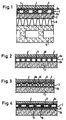
- Fig. 1 shows schematically the structure of a load-bearing, walkable Ceiling construction in cross section.
- the Floor covering 1 for example made of tiles or stone slabs
- the screed layer 2 is for thermal decoupling of the floor coverings from the massive, highly heat conductive Screed layer a double-walled rigid and rigid Insulating body 3 arranged, a continuous, air-filled Includes cavity 4.
- the two cover plates 6a, 6b of the insulating body 3 are with the screed layer 2 or the flooring 1 over an adhesive or mortar layer connected. Run transversely between the cover plates 6a, 6b a variety of rigid support threads 5, but here only schematically and not indicated according to their number are.
- This double-walled insulating body 3 is preferably made of a resin-impregnated textile spacer fabric, that in a known manner from two, by transverse or vertical Web thread structures of interconnected fabric cover layers consists. After an applied one has hardened Resin matrix form this fabric, rigid and rigid sandwich constructions with a free space between the two cover layers.
- Sandwich structures made of textile spacer fabrics of this type are suitable, especially when using glass fiber filaments, because of their exceptional mechanical stiffness and resistance to deformation for thermal separation of two masses lying on top of each other and under load Stratifications, as a result of their transverse thread structures can absorb and transmit high forces. Due the air gap 4 and between the top layers the low mass of the materials making up the plate body make a high quality thermal insulation material is already at a relatively low height compared to Insulation boards made of hard foam or mineral fibers, excellent Provides insulation performance.
- the structure shown in cross section in Fig. 1 load-bearing and walkable ceiling construction also shows explanatory the arranged below the screed layer 2 usual insulation layers 8 made of foam or Fiberboard. Since these plates are not dimensionally stable and are resilient, they must be rigid in themselves load-bearing, solid cement layer or a dimensionally stable Screed layer from 5 to 8 cm floating so to speak become.
- the insulation layer 8 itself is the constructive load-bearing, cast from concrete or from brick Ceiling plate 9 on.
- the ceiling plate 9 thus forms in this embodiment together with the insulation layer 8 and the screed layer 2 is the load-bearing substructure.
- the floor covering 1 at least for solar radiation partially permeable, i.e. transparent or translucent, material formed.
- the floor covering 1 preferably translucent glass tiles or ceramic tiles used in the translucent glass body are embedded.
- the Floor covering 1 with the help of a transparent adhesive connected to the insulating body 3.
- translucent Tiles along with one made from fiberglass textile spacer fabric as an insulating body 3 allows one Use of the floor structure described here according to Art a solar energy trap and enables due to the thermal Decoupling the covering 1 from the heated screed layer 2 with the help of the air gap 4 the storage solar radiation energy into the thermally massive Screed layer 2.
- Wall structure can be the screed layer 2 and the thermal insulation layer 8 omitted.
- the insulating body 3 is here by means of an adhesive bonded to the load-bearing masonry.
- the cover plates 6a, 6b are preferably perforated or drilled to prevent the glue from partially penetrating the cover plates 6a, 6b and thus better adhesion of the Insulating body 3 on the masonry or the surface covering 1 to ensure the insulating body 3.
- Such an inventive Wall construction also allows use one at least partially permeable to solar radiation Surface covering 1.
- Fig. 2 is the air gap 10 through one of the bottom surfaces of the tiles and stone slabs 1 raised embossed line or net-shaped grid 11 brought about. 3 becomes the surface of the textile insulating body 3 trained with knobs 12.
- the screed layer 2 or the lower cover plate 6b facing the screed layer 2 be equipped to reduce emissions.
- the flat cavity 4 facing inner surfaces of the Cover plates and / or the support threads with an emission-reducing Coating, for example by spraying by means of a suitable nozzle tool.
- the equipment of the insulating body 3 with emission-reducing Coatings are more translucent, especially when used Tiles as surface covering 1 advantageous.
- emission-reducing coating (low-E coating) 7 either pyrolytic in the run-up to the curing process of the Applied tiles (at a temperature of approx. 400 - 500 ° C), or on the finished product in a vacuum process be evaporated onto the underside of the tiles. In such a coating is also rational an injection process can be implemented. However, it is preferable a pyrolytically applied coating. It is extraordinary scratch-resistant and resistant to oxidation. These layers can also be used as semiconductor layers as well as metal layers electrically conductive for resistance heating systems be used.
- Low-E coatings can be used for both solar radiation transparent and opaque. At primarily transparent or translucent tiles is therefore, if priority is given to the storage effect in the massive wall structures has to assume more transparent coatings.
- FIGS. 1-3 show an insulating body 3 constructed from two layers 3a, 3b for the thermal decoupling of the screed layer 2 from the floor coverings 1.
- the upper layer 3a of the insulating body 3 is, as described under FIGS. 1-3, made of a hardened resin-coated layer textile spacer fabric formed.
- the lower layer 3b is formed from a single-layer velor-like textile spacer fabric and is adhered to the upper layer 3a via an adhesive layer or already connected to the fabric structure in terms of production technology.
- the adjoining cover layers of the layers 3a and 3b together form the intermediate plate 13.
- the single-layer velor-like textile spacer fabrics used for the lower layer 3b form, after the resin matrix has hardened, row-like, rigid and load-bearing loops 14 arranged vertically on the cover layer, which here are only indicated schematically and extend transversely between the intermediate plate 13 and the screed layer 2.
- an additional stable flat cavity 15 is created between the screed layering and the floor coverings.
- the use of a loop plate body 3b also enables one simple attachment of the insulating body 3 to a wall structure. The attachment to the wall is carried out here with the aid of a layer of mortar or plaster into which the loops 14 are pressed in half, keeping an air-filled cavity 15 free.
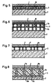
- Fig. 5 shows a floor structure according to the invention in the Insulating body 3 integrated pipes 16 for floor or wall heating systems. It can be copper or plastic pipes, which are from a heat-transferring Fluid flow through. When using more translucent Surface coverings 1 can be used for the heat transfer fluid Excess heat is removed from the solid substructure be used.
- Fig. 6 shows one especially for floor and wall heating suitable floor or wall structure.
- the insulating body 3 consists of two plate bodies or layers 3a and 3b, each consisting of a two-layer textile spacer fabric made and over the each other Adjacent fabric cover layers are bonded together are.
- the plate body receiving the piping system 16 3a goes through to the cold screed or wall side the second plate body 3b thermally insulated.
- This second Plate body 3b can also, corresponding to that in Fig. 4th shown embodiment, made of a velor-like Spacer fabric to be made.
- Advantageously is then the surface of the plate body facing the substructure 3b with an emission-reducing coating.
- the insulating body 3 also line networks for electrical resistance heating inserted or electrical heating foils are inserted.
- the latter can also advantageously between the Flooring and the insulating body in the form of an adhesive film inserted or integrated directly into the floor covering become.
- Fig. 7 shows an insulating body 3, the upper cover layer 6a milled recesses 17 for receiving electrical Has lines and connecting cables.
- Fig. 8 shows an insulating body 3, the flat, air-permeable All or part of the cavity with a foamed Material 18 is filled.
- the insulating body receives an extraordinarily high bending stiffness and shape retention.
- Both the floor coverings 1 and the screed floor 2 have as already shown under Fig. 2 and 3, embossed in a grid raised structures 11a, 11b in order in this way to form an air gap 10a or 10b, the additional Heat transfer resistance generated.
- the at the air gap surfaces adjoining on both sides can then be used for reduction of heat exchange via heat radiation with aluminum foils or low-E layers (not shown here) as in connection with FIGS. 2 and 3 described.
- the embodiment according to FIG. 8 enables due to its high rigidity and surface stability a ceiling structure with screed layers less Thickness.
- the insulating body according to the invention can can also be used directly as load distribution layers.
- such insulating body 3 in an advantageous manner, in particular as a load-distributing Use elements in beamed ceilings.
- You will be below the load-bearing ceiling beams 21 as cladding battens and above as walk-in floor slabs for reception the flooring 1 attached with conventional angle fittings.
- the space between the wooden beams is the usual Foam or fiber insulation 8 filled.
- the insulating body 3 according to Figure 11 to produce in strips or cut accordingly and in parallel at a distance from each other on the substructure, here the screed layer 2, by half the cost of the insulating body material or limit a third.
- Channel structures can then be found both in the form of strips applied insulating body plates 3, as well the spaces 22 between the parallel spaced apart installed insulated body panels realized.
- the strip-shaped insulating body plates 3 are filled in accordance with Figure 8 with a rigid, integral foam off, so you get in the task of channel systems inside of the insulating body a lath-shaped body of great strength and bending stiffness, which, as a slatted frame doweled on the wall surface for efficient application large surfaces can be used.
- the channel structure is then realized solely through the gaps 22.
- Fig. 12 shows the constructive envelope surface structure of a Space.
- the textile hollow plates of the insulating body 3 The wall opens into the hollow panels of the corner area Ceiling envelope.
- the ceiling Insulated body 3 laid from there also in opposite or laterally fitted with hollow panels Open up wall surfaces. Including the floor area, in this way becomes a thermally enveloping space closed cavity system communicating via channel structures realized.
- the room can be heated with underfloor heating or by an integrated in the insulating body plates 3 Hot water or electrically operated baseboard heating 23 be heated (Fig. 13).
- the heat is in the floor area mainly emitted directly to the interior of the room via radiation.
- the insulation to the load-bearing wall is then created by appropriate Design of the back of the insulating body panels, for example through an additional narrow airspace 10b, preferably in conjunction with a low-E layer, such as described in connection with Figures 3 and 8.
- Translucent or partial then have a particularly positive effect translucent surface coverings as they have a large Part of the incoming sun rays and can forward distributed. If this way in the Additional solar energy can occur during the heating season a temperature control the supply through the building heating system generated energy throttled or turned off become.
- the room-enveloping insulating plate system can of course used in this way also in the summer period to excess solar energy record and discharge. But it can also be beneficial Way by feeding in cooled air as a surface cooling system Find application.
- Fig. 14 shows one for the installation of a baseboard heater cross-section of a particularly suitable wall structure according to the invention.
- the textile spacer fabrics are here as Wall cladding used.
- the wall side of the insulator 3 is here again from a single-layer loop plate 3b of the type described in Fig. 4 and adhesive to the Applied to the wall.
- the attachment to the wall is done with the help a layer of mortar or plaster 24, the loops 14 half into this layer, an air-filled cavity 15 keep clear, be pushed in.
- another double wall Plate body 3a may be provided on the single-layer Loop plate 3b is adhesively attached.
- Perforations 25 are provided, which the establishment of a Enable ventilation system.
- the wall structure according to the invention shown here can be advantageous Way with an additional heating function
- a baseboard heater 23 are equipped.
- the Heating energy is applied to the wall element near the floor continuous tubular body arranged in the wall element fed that connected to a hot water heating system are.
- the plate body 3b arranged on the wall which at Embodiment shown here as a single-layer loop plate is designed, forms with the help of the cavity 15 for load-bearing Substructure of the wall element towards a thermal barrier so that the thermal energy supplied to the flat cavity 4 mainly from the room-side covering 1 of the textile Hollow plate body 3a added and towards the room is emitted.
- Wall heating systems can also be advantageously used in this way supply via electrical resistance heaters.
- the heating network can be designed as a baseboard heating system or the lower wall area at the parapet height take in.
- the construction of such electrically heated Systems can alternatively also be used according to the following 15 and 16 embodiments described respectively.
- Tiles for example, can be used as wall coverings, Marble slabs, wooden panels or the usual fabric or Paper wallpapers are used.
- 15 and 16 represent particular embodiments of high efficiency, energy-saving electrical floor and wall heating systems because of the lack of thinner viable It was previously insulation layers with high thermal resistance values not possible to drain thermal energy into the massive Effectively limit floor and wall layers.
- FIG. 15 shows the structure of such a system in use Ceramic flooring 1 made of tiles and stone slabs.
- the heating foils or the heating conductor networks fixed in heating mats 26 are placed directly under the floor covering 1 and with an adhesive layer 27 of high temperature resistance and high flexibility glued. Because of the high Thermal resistance of the textile insulating body 3 and aluminum foil lying between the heating mat and the insulating body or the emission-reducing coating 7a the surface of the insulating body facing the heating mat the heat flow is largely supplied to the floor covering on one side and the space from the stone slabs to heat radiation fed.
- Fig. 16 shows the structure of an electric floor or Wall heating system when using surface coverings 1 with low thermal conductivity, such as in particular Carpet, parquet, PVC and cork coverings.
- the heating foil or Heating plate 26 is assigned a metal plate 28 on the room side, which due to their high thermal conductivity Absorbs heat flow and over the flooring in the room radiates.
- This function can also be performed by a thin storage layer 29 taken over or reinforced by such a layer. It is proposed that a thin, reinforced with a textile fabric 30 screed, gypsum, or cement layer, as shown in FIG. 16. In this way, extremely thin, load-bearing, Manufacture rigid and dimensionally stable plate constructions.
- a heating conductor network can be woven in (in Fig. 16 not shown). In such a case, the heating mat is not required 26 and the metal plate 28. Opposite the load-bearing
- the textile can be used to support the floor or wall structure Insulating body 3 with additional air-filled spaces 10b and an aluminum foil or an emission-reducing Coating 7b as a thermal radiation barrier be shielded.
- FIG. 17 shows a possible wall fastening of the insulating body 3 to a cross batten 34 with the aid of an adhesive connection 31.
- the bond can be done by penetrating the adhesive into predetermined perforations of the wall-side cover plate 6b and subsequent curing of the adhesive mechanically secured become.
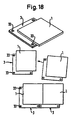
- a laying of tiles according to this shown in Fig. 18 Design ensures a reliable Sealing of the tile subsurface, because they form no gaps running through to the wall or floor substructure out. A tiled outer wall remains secured against driving rain.
- This version also proves to be advantageous for laying work. It helps to better align the surface geometry and in particular for exact compliance the joint width.
- the through holes 33 of the insulating body plates 3 serve each for doweling on the load-bearing wall structures. alternative for this, the tiles can be drilled using these holes Adhesive scraps can be fixed and attached.
- the insulating body plates 3 perforations on one or both sides can be provided that fix or glue favor with the wall structure and with the surface covering. The adhesive then partially penetrates the perforation on.
Landscapes
- Engineering & Computer Science (AREA)
- Architecture (AREA)
- Civil Engineering (AREA)
- Structural Engineering (AREA)
- Physics & Mathematics (AREA)
- Acoustics & Sound (AREA)
- Electromagnetism (AREA)
- Life Sciences & Earth Sciences (AREA)
- Wood Science & Technology (AREA)
- Building Environments (AREA)
- Floor Finish (AREA)
Claims (39)
- Structure de plancher, de plafond ou de mur, dans laquelle un corps isolant (3) est agencé entre une fondation portante et un revêtement de surface (1), caractérisée en ce que le corps isolant (3) présente une plaque de recouvrement supérieure (6a) voisine du revêtement de surface (1) et une plaque de recouvrement inférieure (6b) voisine de la fondation et est formé par une multitude de fils de soutien (5 ; 14) rigides à la flexion s'étendant transversalement entre la plaque de recouvrement supérieure (6a) et la plaque de recouvrement inférieure (6b), lesquels, pour obtenir à l'état d'utilisation un découplage thermique de la fondation par rapport au revêtement, haubanent de manière portante entre ceux-ci une cavité (4 ; 15) qui maintient sa forme.
- Structure selon la revendication 1, caractérisée en ce que les fils de soutien (5 ; 14) sont formés par des fibres de verre, de céramique, de matière plastique ou de fibres de carbone.
- Structure selon la revendication 1, caractérisée en ce que les fils de soutien (5 ; 14) sont formés par des fibres organiques ou par des fibres naturelles telles que des fibres en chanvre ou en autres produits végétaux.
- Structure selon l'une des revendications 1 à 3, caractérisée en ce que les fils de soutien (5 ; 14) sont agencés en se croisant.
- Structure selon l'une des revendications 1 à 4, caractérisée en ce que les fils de soutien (5 ; 14) présentent un titre moyen dans la plage d'environ 20 à 80 tex.
- Structure selon l'une des revendications 1 à 5, caractérisée en ce que les fils de soutien (5 ; 14) sont agencés avec une densité d'entre environ 10 à 60 fils/cm2.
- Structure selon l'une des revendications 1 à 6, caractérisée en ce que le corps isolant (3) est formé par un textile tissé ou à mailles formant espaceur par imprégnation avec une résine et par durcissement.
- Structure selon l'une des revendications 1 à 7, caractérisée en ce que la plaque de recouvrement supérieure (6a) est reliée au revêtement (1) et/ou la plaque de recouvrement inférieure (6b) est reliée avec la fondation.
- Structure selon la revendication 8, caractérisée en ce que des espaces intermédiaires (10a) remplis d'air sont réalisés entre le revêtement (1) et la plaque de recouvrement supérieure (6a).
- Structure selon la revendication 8 ou 9, caractérisée en ce que des espaces intermédiaires (10b) remplis d'air sont réalisés entre la fondation et la plaque de recouvrement inférieure (6b).
- Structure selon l'une des revendications 8 à 10, caractérisée en ce qu'une couche réduisant les émissions (7b) est introduite entre la fondation et le corps isolant (3).
- Structure selon l'une des revendications 8 à 11, caractérisée en ce qu'une couche réduisant les émissions (7 ; 7a) est introduite dans les espaces intermédiaires (10a) entre le revêtement (1) et la plaque de recouvrement supérieure (6a).
- Structure selon l'une des revendications 1 à 12, caractérisée en ce que la surface intérieure du corps isolant (3), tournée vers la cavité (4 ; 15), y compris les fils de soutien (5 ; 14), est pourvue au moins partiellement d'une couche réduisant les émissions (7 ; 7a).
- Structure selon l'une des revendications 8 à 13, caractérisée en ce que le corps isolant (3) présente au moins une plaque intermédiaire (13) qui est reliée par les fils de soutien (5 ; 14) avec la plaque de recouvrement supérieure (6a) et/ou avec la plaque de recouvrement inférieure (6b).
- Structure selon l'une des revendications 8 à 14, caractérisée en ce que le revêtement (1) et la plaque de recouvrement supérieure (6a) sont perforés pour aérer et ventiler un espace.
- Structure selon l'une des revendications 1 à 15, caractérisée en ce que la cavité (4 ; 15) est remplie d'air.
- Structure selon l'une des revendications 1 à 15, caractérisée en ce que la cavité (4) est remplie au moins partiellement d'une masse de mousse de matière plastique (18).
- Structure selon l'une des revendications 1 à 17, caractérisée en ce que dans le corps isolant (3) sont disposées des structures intérieures (16 ; 22) en forme de canaux.
- Structure selon la revendication 18, caractérisée en ce que les structures intérieures en forme de canaux sont formées par des conduites (16) intégrées dans le corps isolant (3).
- Structure selon la revendication 18 ou 19, caractérisée en ce que les structures intérieures (16 ; 22) en forme de canaux sont chargées d'air chaud, d'air froid ou d'un fluide conducteur de chaleur.
- Structure selon l'une des revendications 18 à 20, caractérisée en ce que les structures intérieures (16 ; 22) en forme de canaux sont réalisées de manière à envelopper un espace et sont en communication les unes avec les autres.
- Structure selon l'une des revendications 1 à 21, caractérisée en ce que le corps isolant (3) et le revêtement de surface (1) sont au moins partiellement transparents pour le rayonnement solaire.
- Structure selon la revendication 22, caractérisée en ce que le revêtement de surface (1) est au moins partiellement translucide.
- Structure selon l'une des revendications 22 ou 23, caractérisée en ce que le revêtement de surface (1) est constitué au moins partiellement par des carreaux translucides.
- Structure selon l'une des revendications 22 à 24, caractérisée en ce que le corps isolant (3) est formé par un textile tissé ou à mailles en fibres de verre formant espaceur.
- Structure selon l'une des revendications 1 à 25, caractérisée en ce que le revêtement de surface (1) est constitué par des carreaux opaques, translucides ou partiellement translucides, dont la surface tournée vers le corps isolant (3) est pourvue d'une couche réduisant les émissions.
- Structure selon la revendication 26, caractérisée en ce que la couche réduisant les émissions est appliquée par pyrolyse.
- Structure selon l'une des revendications 1 à 27, caractérisée en ce que le corps isolant (3) est formé par des plaques en forme de bandes posées parallèlement à distance les unes des autres.
- Structure selon l'une des revendications 1 à 27, caractérisée en ce que le revêtement de surface (1) est constitué par des dalles de carrelage qui sont agencées en décalage bilatéral par rapport au corps isolant (3) formé par des plaques de même format.
- Structure selon l'une des revendications 1 à 21, caractérisée en ce qu'un chauffage à résistance électrique est intégré au corps isolant.
- Structure selon l'une des revendications 1 à 21, caractérisée en ce qu'un chauffage à résistance électrique (26) est agencé entre le revêtement (1) et le corps isolant (3).
- Structure selon l'une des revendications 30 ou 31, caractérisée en ce qu'entre le chauffage à résistance électrique (26) et le revêtement est agencé une plaque métallique (20) et/ou une couche à accumulation de chaleur (29) destinée à recevoir le flux de chaleur et à rayonner vers l'espace l'énergie calorifique engendrée par le chauffage à résistance électrique par l'intermédiaire du revêtement (1).
- Structure selon l'une des revendications 1 à 21, caractérisée en ce qu'une couche accumulant la chaleur (29) est agencée entre le corps isolant (3) et le revêtement, un chauffage à résistance électrique étant intégré dans la couche à accumulation de chaleur.
- Structure selon la revendication 33, caractérisée en ce que la couche à accumulation de chaleur (29) est une couche de chape, de plâtre ou de ciment renforcée par un (30) textile, et en ce que le chauffage à résistance électrique contient un réseau conducteur de chaleur tissé dans le textile.
- Structure selon l'une des revendications 32 à 34, caractérisée en ce que le chauffage à résistance électrique est réglable en fonction de la température extérieure ou de la température ambiante.
- Utilisation de tissus textiles tissés ou à mailles formant espaceurs, dont les fils de soutien rigides à la flexion peuvent tendre de manière portante une cavité maintenant sa forme, pour la construction de planchers, de plafonds ou de murs hautement thermo-isolants selon l'une des revendications 1 à 35.
- Utilisation de tissus textiles tissés ou à mailles formant espaceurs selon la revendication 36, caractérisée en ce que les tissus textiles tissés ou à mailles formant espaceurs sont enduits de résine et sont par conséquent durcis pour former un corps isolant rigide à la flexion, autoporteur et recevant des charges.
- Utilisation selon la revendication 37, caractérisée en ce que le corps isolant présente deux surfaces de recouvrement (6a, 6b), au moins une des couches de recouvrement étant reliée avec une plaque de bois ou une couche de bois de placage (32).
- Utilisation selon la revendication 38, caractérisée en ce que le corps isolant est recouvert sur son bord périphérique par une masse de mousse de matière plastique durcissante et est pourvu d'une gorge sur au moins une de ses surfaces d'arêtes, à la manière d'un panneau de bois.
Applications Claiming Priority (5)
| Application Number | Priority Date | Filing Date | Title |
|---|---|---|---|
| DE19502238 | 1995-01-25 | ||
| DE19502238A DE19502238A1 (de) | 1995-01-25 | 1995-01-25 | Hochwärmedämmend ausgerüsteter Boden-, Decken- oder Wandaufbau |
| DE29520224U DE29520224U1 (de) | 1995-01-25 | 1995-12-20 | Hochwärmedämmend ausgerüsteter Boden-, Decken- oder Wandaufbau |
| DE29520224U | 1995-12-20 | ||
| PCT/EP1996/000289 WO1996023110A1 (fr) | 1995-01-25 | 1996-01-24 | Structure de plancher, de plafond ou de cloison assurant une tres bonne isolation thermique |
Publications (2)
| Publication Number | Publication Date |
|---|---|
| EP0805902A1 EP0805902A1 (fr) | 1997-11-12 |
| EP0805902B1 true EP0805902B1 (fr) | 2004-09-29 |
Family
ID=26011855
Family Applications (1)
| Application Number | Title | Priority Date | Filing Date |
|---|---|---|---|
| EP96902916A Expired - Lifetime EP0805902B1 (fr) | 1995-01-25 | 1996-01-24 | Structure de plancher, de plafond ou de cloison assurant une tres bonne isolation thermique |
Country Status (5)
| Country | Link |
|---|---|
| EP (1) | EP0805902B1 (fr) |
| AT (1) | ATE278075T1 (fr) |
| AU (1) | AU4713896A (fr) |
| DE (1) | DE19680027D2 (fr) |
| WO (1) | WO1996023110A1 (fr) |
Families Citing this family (4)
| Publication number | Priority date | Publication date | Assignee | Title |
|---|---|---|---|---|
| ES2182700B1 (es) * | 2001-05-31 | 2004-06-16 | Construcciones Polies-Yes Pores, S.L. | Pavimento aislante. |
| EP2423398A1 (fr) * | 2010-08-23 | 2012-02-29 | insu-fast GmbH | Dispositif d'isolation intérieure d'une paroi de composant |
| EP3626902B8 (fr) * | 2018-09-21 | 2021-11-24 | Martin Kleppe | Structure de paroi composite pour une construction |
| CN114103375A (zh) * | 2021-11-26 | 2022-03-01 | 铁力山(北京)控制技术有限公司 | 一种具有储热性能的碳纤维复合电热木板及其制备方法 |
Family Cites Families (6)
| Publication number | Priority date | Publication date | Assignee | Title |
|---|---|---|---|---|
| DE2013115A1 (de) * | 1970-03-19 | 1971-09-30 | Becker O | Flexibles Verbundelement mit Isolierung |
| DE2241836A1 (de) * | 1972-08-25 | 1974-03-07 | Mahr Soehne Gmbh Theo | Luftfuehrungs-rohrbatterien fuer fussboden-warmluftheizung |
| DE3723681A1 (de) * | 1987-07-17 | 1989-01-26 | Vorwerk Co Interholding | Bauteil auf velours-gewebebasis und verfahren zu seiner herstellung |
| NL8902815A (nl) * | 1989-11-14 | 1991-06-03 | Cornelius Aaldijk | Buigzaam scheurdoorzettingverhinderend scheidbaar baanvormig verbindingsmateriaal, bestaande uit twee, door een scheidingslaag gescheiden en door verbreekbare bruggen met elkaar verbonden bevestigingslagen, alsmede werkwijze voor het gebruik van dit materiaal en gevormde bekledingslaagopbouw. |
| FI87480C (fi) * | 1990-11-27 | 1993-01-11 | Racert Oy | Ljusgenomslaeppande vaermeisolering |
| FR2703378B1 (fr) * | 1993-03-30 | 1995-06-02 | Pierre Clement | Elément de paroi à isolation dynamique pour le renouvellement d'air dans les bâtiments en vue de les rendre plus confortables et plus économiques. |
-
1996
- 1996-01-24 AT AT96902916T patent/ATE278075T1/de not_active IP Right Cessation
- 1996-01-24 AU AU47138/96A patent/AU4713896A/en not_active Abandoned
- 1996-01-24 DE DE19680027T patent/DE19680027D2/de not_active Ceased
- 1996-01-24 EP EP96902916A patent/EP0805902B1/fr not_active Expired - Lifetime
- 1996-01-24 WO PCT/EP1996/000289 patent/WO1996023110A1/fr not_active Ceased
Also Published As
| Publication number | Publication date |
|---|---|
| AU4713896A (en) | 1996-08-14 |
| WO1996023110A1 (fr) | 1996-08-01 |
| ATE278075T1 (de) | 2004-10-15 |
| EP0805902A1 (fr) | 1997-11-12 |
| DE19680027D2 (de) | 1999-05-12 |
Similar Documents
| Publication | Publication Date | Title |
|---|---|---|
| EP2390433B1 (fr) | Eléments préfabriqués et leur procédé de fabrication | |
| AT403599B (de) | Fertigbauelement sowie verfahren zur herstellung und bauseitigen anwendung | |
| EP3532681B1 (fr) | Structure de plafond multifonctionnelle | |
| DE29916723U1 (de) | Modulplatte für elektrische Flächenheizung von Fußböden oder Wänden | |
| EP0805902B1 (fr) | Structure de plancher, de plafond ou de cloison assurant une tres bonne isolation thermique | |
| DE4338185C2 (de) | Verfahren zur Herstellung eines Fertighauses | |
| DE3919862A1 (de) | Verlorene schalungen | |
| DE29520224U1 (de) | Hochwärmedämmend ausgerüsteter Boden-, Decken- oder Wandaufbau | |
| DE19748352A1 (de) | Verfahren und Schichtelemente zur thermischen und körperorientierten Beherrschung und Steuerung des Innenklimas | |
| EP0111763B1 (fr) | Carreau de céramique, carreau de céramique modulaire | |
| EP1826330A2 (fr) | Procédé destiné à la fabrication d'éléments muraux semi-finis | |
| EP0132499B1 (fr) | Système de bâtiment à chauffage à basse température, fermé et intégré, respectivement à refroidissement équivalent | |
| AT519367B1 (de) | Wand für ein gebäude | |
| EP2706159B1 (fr) | Procédé destiné à réduire ou éliminer les dégâts ou formations de moisissures et/ou d'humidité dans des zones à isolation thermique, et les batiments et parties de batiments proteges contre les dégâts ou formations de moisissures et/ou d'humidité | |
| DE102016117032A1 (de) | Deckschichtbauelement und Trockenbausystem | |
| WO2023285301A1 (fr) | Micro-maison modulaire empilable et transportable sur route | |
| WO1997015171A9 (fr) | Chauffage electrique par resistance pour la climatisation d'appartements et de batiments | |
| DE3010063A1 (de) | Klimatisierungseinrichtung fuer gebaeude | |
| DE3021537A1 (de) | Isolierung fuer den hoch- und tiefbau | |
| AT507427B1 (de) | Dämmelement | |
| AT405312B (de) | Wandaufbau | |
| DE9419795U1 (de) | Wandkonstruktion für und Bauwerk in Ständerbauweise | |
| DE102009016379A1 (de) | Verlegemörtelboden mit Fussbodenheizung | |
| EP0744505B1 (fr) | Balcon de toit ou similaire | |
| DE3109419A1 (de) | Heizungssystem |
Legal Events
| Date | Code | Title | Description |
|---|---|---|---|
| PUAI | Public reference made under article 153(3) epc to a published international application that has entered the european phase |
Free format text: ORIGINAL CODE: 0009012 |
|
| 17P | Request for examination filed |
Effective date: 19970826 |
|
| AK | Designated contracting states |
Kind code of ref document: A1 Designated state(s): AT CH DE GB LI |
|
| 17Q | First examination report despatched |
Effective date: 19971106 |
|
| GRAP | Despatch of communication of intention to grant a patent |
Free format text: ORIGINAL CODE: EPIDOSNIGR1 |
|
| GRAS | Grant fee paid |
Free format text: ORIGINAL CODE: EPIDOSNIGR3 |
|
| GRAA | (expected) grant |
Free format text: ORIGINAL CODE: 0009210 |
|
| AK | Designated contracting states |
Kind code of ref document: B1 Designated state(s): AT CH DE GB LI |
|
| PG25 | Lapsed in a contracting state [announced via postgrant information from national office to epo] |
Ref country code: GB Free format text: LAPSE BECAUSE OF FAILURE TO SUBMIT A TRANSLATION OF THE DESCRIPTION OR TO PAY THE FEE WITHIN THE PRESCRIBED TIME-LIMIT Effective date: 20040929 |
|
| REG | Reference to a national code |
Ref country code: GB Ref legal event code: FG4D Free format text: NOT ENGLISH |
|
| REG | Reference to a national code |
Ref country code: CH Ref legal event code: EP |
|
| REF | Corresponds to: |
Ref document number: 59611102 Country of ref document: DE Date of ref document: 20041104 Kind code of ref document: P |
|
| REG | Reference to a national code |
Ref country code: CH Ref legal event code: NV Representative=s name: BUGNION S.A. |
|
| GBV | Gb: ep patent (uk) treated as always having been void in accordance with gb section 77(7)/1977 [no translation filed] |
Effective date: 20040929 |
|
| PLBE | No opposition filed within time limit |
Free format text: ORIGINAL CODE: 0009261 |
|
| STAA | Information on the status of an ep patent application or granted ep patent |
Free format text: STATUS: NO OPPOSITION FILED WITHIN TIME LIMIT |
|
| 26N | No opposition filed |
Effective date: 20050630 |
|
| PGFP | Annual fee paid to national office [announced via postgrant information from national office to epo] |
Ref country code: AT Payment date: 20070111 Year of fee payment: 12 |
|
| PGFP | Annual fee paid to national office [announced via postgrant information from national office to epo] |
Ref country code: CH Payment date: 20070115 Year of fee payment: 12 |
|
| PGFP | Annual fee paid to national office [announced via postgrant information from national office to epo] |
Ref country code: DE Payment date: 20070327 Year of fee payment: 12 |
|
| REG | Reference to a national code |
Ref country code: CH Ref legal event code: PL |
|
| PG25 | Lapsed in a contracting state [announced via postgrant information from national office to epo] |
Ref country code: LI Free format text: LAPSE BECAUSE OF NON-PAYMENT OF DUE FEES Effective date: 20080131 Ref country code: DE Free format text: LAPSE BECAUSE OF NON-PAYMENT OF DUE FEES Effective date: 20080801 Ref country code: CH Free format text: LAPSE BECAUSE OF NON-PAYMENT OF DUE FEES Effective date: 20080131 |
|
| PG25 | Lapsed in a contracting state [announced via postgrant information from national office to epo] |
Ref country code: AT Free format text: LAPSE BECAUSE OF NON-PAYMENT OF DUE FEES Effective date: 20080124 |