EP0805902B1 - Floor, ceiling or wall structure with highly effective thermal insulation - Google Patents
Floor, ceiling or wall structure with highly effective thermal insulation Download PDFInfo
- Publication number
- EP0805902B1 EP0805902B1 EP96902916A EP96902916A EP0805902B1 EP 0805902 B1 EP0805902 B1 EP 0805902B1 EP 96902916 A EP96902916 A EP 96902916A EP 96902916 A EP96902916 A EP 96902916A EP 0805902 B1 EP0805902 B1 EP 0805902B1
- Authority
- EP
- European Patent Office
- Prior art keywords
- insulating body
- covering
- floor
- layer
- wall
- Prior art date
- Legal status (The legal status is an assumption and is not a legal conclusion. Google has not performed a legal analysis and makes no representation as to the accuracy of the status listed.)
- Expired - Lifetime
Links
Images


Classifications
-
- E—FIXED CONSTRUCTIONS
- E04—BUILDING
- E04B—GENERAL BUILDING CONSTRUCTIONS; WALLS, e.g. PARTITIONS; ROOFS; FLOORS; CEILINGS; INSULATION OR OTHER PROTECTION OF BUILDINGS
- E04B1/00—Constructions in general; Structures which are not restricted either to walls, e.g. partitions, or floors or ceilings or roofs
- E04B1/62—Insulation or other protection; Elements or use of specified material therefor
- E04B1/74—Heat, sound or noise insulation, absorption, or reflection; Other building methods affording favourable thermal or acoustical conditions, e.g. accumulating of heat within walls
- E04B1/76—Heat, sound or noise insulation, absorption, or reflection; Other building methods affording favourable thermal or acoustical conditions, e.g. accumulating of heat within walls specifically with respect to heat only
- E04B1/7675—Insulating linings for the interior face of exterior walls
-
- E—FIXED CONSTRUCTIONS
- E04—BUILDING
- E04B—GENERAL BUILDING CONSTRUCTIONS; WALLS, e.g. PARTITIONS; ROOFS; FLOORS; CEILINGS; INSULATION OR OTHER PROTECTION OF BUILDINGS
- E04B1/00—Constructions in general; Structures which are not restricted either to walls, e.g. partitions, or floors or ceilings or roofs
- E04B1/62—Insulation or other protection; Elements or use of specified material therefor
- E04B1/74—Heat, sound or noise insulation, absorption, or reflection; Other building methods affording favourable thermal or acoustical conditions, e.g. accumulating of heat within walls
- E04B1/76—Heat, sound or noise insulation, absorption, or reflection; Other building methods affording favourable thermal or acoustical conditions, e.g. accumulating of heat within walls specifically with respect to heat only
- E04B1/7608—Heat, sound or noise insulation, absorption, or reflection; Other building methods affording favourable thermal or acoustical conditions, e.g. accumulating of heat within walls specifically with respect to heat only comprising a prefabricated insulating layer, disposed between two other layers or panels
- E04B1/7612—Heat, sound or noise insulation, absorption, or reflection; Other building methods affording favourable thermal or acoustical conditions, e.g. accumulating of heat within walls specifically with respect to heat only comprising a prefabricated insulating layer, disposed between two other layers or panels in combination with an air space
-
- E—FIXED CONSTRUCTIONS
- E04—BUILDING
- E04C—STRUCTURAL ELEMENTS; BUILDING MATERIALS
- E04C2/00—Building elements of relatively thin form for the construction of parts of buildings, e.g. sheet materials, slabs, or panels
- E04C2/02—Building elements of relatively thin form for the construction of parts of buildings, e.g. sheet materials, slabs, or panels characterised by specified materials
- E04C2/10—Building elements of relatively thin form for the construction of parts of buildings, e.g. sheet materials, slabs, or panels characterised by specified materials of wood, fibres, chips, vegetable stems, or the like; of plastics; of foamed products
- E04C2/16—Building elements of relatively thin form for the construction of parts of buildings, e.g. sheet materials, slabs, or panels characterised by specified materials of wood, fibres, chips, vegetable stems, or the like; of plastics; of foamed products of fibres, chips, vegetable stems, or the like
-
- E—FIXED CONSTRUCTIONS
- E04—BUILDING
- E04F—FINISHING WORK ON BUILDINGS, e.g. STAIRS, FLOORS
- E04F15/00—Flooring
- E04F15/18—Separately-laid insulating layers; Other additional insulating measures; Floating floors
-
- E—FIXED CONSTRUCTIONS
- E04—BUILDING
- E04F—FINISHING WORK ON BUILDINGS, e.g. STAIRS, FLOORS
- E04F15/00—Flooring
- E04F15/18—Separately-laid insulating layers; Other additional insulating measures; Floating floors
- E04F15/182—Underlayers coated with adhesive or mortar to receive the flooring
-
- E—FIXED CONSTRUCTIONS
- E04—BUILDING
- E04F—FINISHING WORK ON BUILDINGS, e.g. STAIRS, FLOORS
- E04F15/00—Flooring
- E04F15/18—Separately-laid insulating layers; Other additional insulating measures; Floating floors
- E04F15/185—Underlayers in the form of studded or ribbed plates
-
- E—FIXED CONSTRUCTIONS
- E04—BUILDING
- E04F—FINISHING WORK ON BUILDINGS, e.g. STAIRS, FLOORS
- E04F2203/00—Specially structured or shaped covering, lining or flooring elements not otherwise provided for
- E04F2203/06—Specially structured or shaped covering, lining or flooring elements not otherwise provided for comprising two layers fixedly secured to one another, in offset relationship in order to form a rebate
- E04F2203/065—Specially structured or shaped covering, lining or flooring elements not otherwise provided for comprising two layers fixedly secured to one another, in offset relationship in order to form a rebate in offset relationship longitudinally as well as transversely
Definitions
- the invention relates to a high thermal insulation Floor, ceiling or wall structure, in which an insulating body between a load-bearing substructure and a surface covering is arranged.
- floor coverings such as fine ceramic tiles, ceramic split tiles, floor clinker tiles, PVC, rubber or cork boards, but also Wood parquet and textile coverings usually at least 5 to 8 cm thick cement screed layers applied.
- the flooring thus directly border on voluminous, massive layers of material with high thermal mass, which has high thermal conductivity and have a large heat penetration number.
- floor coverings with the exception of thick cork coverings and deep-pile carpets, always count as cold feet. They are up to the demands after a comfortable room climate due to the intensive heat dissipation on the massive, constructively bearing and loads receiving floor substructure.
- the floor or ceiling structure as usual, sufficient under the screed layer Contains heat insulation layer, because the first thing is the sensation of heat when standing and walking on floors by temperature the contact surface, i.e. the temperature of the floor surface, dependent.
- the actual heat and Soundproofing layers on the screed layer which in turn serves as a substructure for the actual floor covering one with walkable and insulated ceiling constructions as rigid, self-supporting and load-bearing Always shift before.
- EP 0 428 201 describes bridging threads in a dense connecting layer, whereby gravitational forces are to be compensated for. An insulating body is not addressed in EP O 428 201.
- the object of the invention is therefore the existing thermal Defects in floor or ceiling structures, in particular for structures with ceramic and stoneware coverings, as well as the same defects in wall structures with insufficient self-insulation to fix so as to make the rooms comfortable Alignment of the surface temperatures of their envelope surfaces increase.
- a floor, ceiling or wall structure according to the features of claim 1 provided.
- An insulating body in between one structurally load-bearing substructure and a surface covering arranged. Any conventional, layering underlaid on a wall or floor covering.
- the covering can, for example, be made of ceramic tiles, Stoneware panels, plastic panels, wooden parquet or also Carpets exist.
- the covering in addition to the aforementioned materials, can also be wallpaper or include a simple coat of paint.
- the invention Floor, ceiling or wall structure is characterized by that the insulating body through a variety of cross between the surface covering and the substructure, rigid Support threads are formed, which are used for thermal decoupling the substructure of the covering between these one Cover the flat and shape-retaining cavity.
- the surface covering is preferably for solar radiation at least partially permeable, i.e. transparent or translucent.
- a suitable measure to effectively reduce heat transfer between two superimposed, highly thermally conductive Solid bodies is the storage of a dormant, low convection air layer between these solids for Decoupling the heat exchange. That haunted Principle is therefore the floor, ceiling or Wall coverings thermally from their base layers through a Isolate the insulating body between the coverings and their base layers are only flat and form-retaining Open the cavity. This requires the provision here a powerful thermal insulation material with sufficient independent surface stability, rigidity and Load capacity, which as a constructive material itself forces can record and transmit.
- the insulator is therefore by a variety from across between the surface covering and the substructure extending, rigid support threads formed.
- the cavity is preferably filled with air, but can also be a commonly used for thermal insulation Plastic foam mass included.
- the cavity can be filled with a translucent material with low thermal conductivity, such as have a silica airgel structure.
- the insulation material proposed here is able to loads acting on floor coverings over large areas without changing its shape, for example on the floating one Screed as a substructure, to be transferred or for wall coverings to take the loads acting here.
- the Load capacity is based on the bracing effect of the multitude of essentially axially loaded support threads. Despite of this multitude of threads, these have a smaller one Proportion of area than conventional struts and bend hence the formation of cold bridges. Together with the The thread structure leads into the air layer embedded in the cavity of the insulator so that the convection based heat exchange between the covering and the load-bearing Substructure is almost completely eliminated.
- the support threads of the insulating body are preferably formed from inorganic fibers, such as glass, ceramic, plastic or carbon fibers.
- organic fibers and in particular biological fibers or natural fibers can also be used, such as fibers made from hemp or other vegetable products.
- the support threads preferably have an average fineness in the range from approximately 20 to 80 tex and are arranged in a density of between approximately 10 to approximately 60 threads / cm 2 .
- Such an insulating body has excellent thermal insulation properties, since heat transfer by heat conduction is practically eliminated by the use of lightweight materials with a small internal volume, as well as the low mass of the extremely thin, yet load-bearing and force-transmitting support threads.
- the high strength and bending stiffness of the insulating body can be further increased in that the supporting threads are arranged crossing one another. The triangulation effect associated with this leads to an overall rigid bracing.
- the insulating body an upper and / or a lower cover plate, wherein the upper cover plate with the covering and the lower cover plate is connected to the substructure.
- the insulating body can also still have one or more intermediate plates, wherein the intermediate plates then over the support threads together or connected to the upper and / or lower cover plate are. In such a case, the insulating body is off two or more layers are formed, the individual Layers even in the manner of a single-layer insulating body are built up.
- Such an insulating body is advantageously made of a textile spacer fabric or knitted fabric by impregnation with a resin and curing the sandwich construction thus obtained formed like this in principle from the German Publication DE 37 23 681 A1 is known.
- this is the production of textile spacer fabrics and knitted fabrics, as well as their use to form rigid, described sandwich-like components.
- the spacer fabrics and knitted fabrics usually as spacer layers for the production of various fiber composite materials used.
- the spacer fabrics to be used exist generally from cover layers of a textile material, in particular made of ceramic, glass, plastic or carbon fibers, or from mixtures of such materials.
- the top layers are caused by threads entering vertically or at an angle, so-called web threads, connected to each other.
- the bridge threads are preferably twisted and hold scaffold the two fabric layers at a distance. In doing so, they form in the form of a loop or mesh structure essentially rows of bars standing vertically on the cover layers, whereby the top layers are additionally diagonally Thread structures running to the rows of webs linked can be.
- the spacer fabrics and knitted fabrics are used in their processing usually soaked or impregnated with resin.
- the Excess resin is then between foils or Rolls pressed out. They depend on the impregnation Bridge threads due to the material properties and the binding structure generated restoring forces without tools back to its original height and enable calibrating distances due to their definable length to the top layers.
- the strength of after curing The sandwich construction resulting from resin sizes is used in essentially by the arrangement and the height of the web threads certainly.
- Rowings yarns are also known for the construction of three-dimensional textile plate structures, especially those with distances of over 12 mm between the top layers. Rowings yarns are made of yarn endlessly drawn thicker glass threads. You don't have the ability to engage in the curing process after resin wetting to erect yourself due to your own twist, however, spacer fabrics are made from this material cost-effective. The erection process succeeds here a mechanical pulling apart of the top layers before final curing of the resin matrix.
- the invention therefore also relates to the use of such spacer fabrics or knitted fabrics according to the features of claim 36.
- the use relates to the construction of highly thermally insulated room envelope structures, i.e. floors, ceilings or walls, and especially in shape Pre-fabricated insulating board bodies with large areas, those made of resin-impregnated and hardened Spacer fabrics are formed.
- a single-layer, Use velvet-like spacer fabrics For the purposes of the invention, a single-layer, Use velvet-like spacer fabrics.
- One made from such a fabric by impregnating with resins and then curing the resin matrix Insulating body has only one cover plate on which Loop or mesh structures are arranged in rows essentially perpendicular to the plate.
- the thermal decoupling of floor or wall coverings from the massive layers of the substructure of the floor load-bearing masonry of the room walls by a preferably double-walled, rigid and rigid plate body, which forms a continuous flat cavity also the advantage that through appropriate training and Arrangement of the support threads or by integrating pipelines quasi channel-shaped inner structures in the insulating body can be set up that allow the flat insulating body not only as a passive thermal insulation material, but also as a conductive for heat transfer, active thermal insulation system, for example as Floor or wall heating system in the manner of a holocaust system, to use.
- honeycomb-shaped Offer wall structures as stiffening spacers not this advantage.
- the honeycomb structures form in the panel body no flat, continuous cavities, but just a multitude of separate small dreams.
- the double-walled textile plate body according to the invention contrast, whose cover plates by spacing, in rows arranged web threads are stiffened together and thereby ordered, essentially channel-shaped structures train, can be both as one with warm air or heat distribution system to be charged with a heat transfer fluid, but also as a large-scale system Represent heat convectors.
- Cooling systems avoided the immediate cold air in the room let it flow in and thus often perceived as cause convective air currents. These cooling systems especially because of their hygienic problems criticized. Except for the inevitable raising of dust are they given by the medical side because of the danger of Introduction and transmission of disease germs as considered questionable.
- the room is cooled not about convective air circulation. Rather, through Lowering the surface temperatures of the room envelope man is able to use his excess heat through Dissipate radiation exchange over these cooled surfaces. In the same way as for a heated by heat radiation Here, too, space is transformed into an exchange of radiation creates a comfortable indoor climate.
- the Cooling medium in a circumferentially closed channel system Analogous to underfloor heating, it is required inside the room neither an air exchange nor the supply of cold air. The unacceptable swirling of dust is also eliminated like the spread of disease germs.
- the space envelope structure according to the invention, the one Flat, underlaid floor, wall and / or ceiling coverings Provides hollow plate system with channel-like inner structures, can advantageously also for more efficient use the solar radiation energy incident on the room for the room heating after a previously unknown and practiced concept to achieve higher storage rates find meaningful application in the wall structures.
- the construction of the space envelope surfaces according to the invention enables it is the one that occurs briefly in the heating period solar energy supply in the passive envelope of the Store the building immediately.
- Insulating body preferably one made of glass fibers textile spacer fabric, together with translucent surface coverings
- Suitable for use as a translucent surface covering translucent tiles in particular This is what it is about usually small-format tiles from a glass-like Material for the manufacture of which is a glass dust at 700 pressed or poured into a suitable mold up to 800 ° C becomes.
- tiles made of pure ceramic can also be used Masses are used in the glass-like Moldings are embedded. Glass tiles of the aforementioned Kind, mostly with translucent colored decor, are already known and are increasingly used as decorative wall and floor linings used for bathrooms and swimming pools. Are also as translucent surface covering Suitable marble slabs.
- the solar radiation incident through transparent window surfaces is known not to remain entirely in the Room. Reflected on opaque, bright room envelopes occurs Part of the radiation through the window surfaces again Outside. If the envelope is lined with translucent Wall, ceiling and floor coverings are shone through these surfaces. The solar radiation is from the one behind it Masonry absorptively added. There are no reflections instead and so far no radiation losses through transparent window surfaces. Through translucent wall cladding the type described is therefore a high one Degree of utilization of the solar radiation entering the room reached.
- the above-described formation of channel-like Internal structures in the hollow body according to the invention can through dissipation and even distribution of thermal energy in the wall structures still increase this Contribute to the degree of utilization.
- the coverings of the room envelope surfaces and the upper cover plates of the insulating body connected to them are perforated, in particular in the ceiling area.
- the double-walled insulating body integrated into the space enveloping surfaces and assembled into a closed cavity can advantageously also be set up as an automatic ventilation system or as a system for forced ventilation with a heat exchange function. Because of the large exchange areas, this system has high energy efficiency.
- the hollow chamber elements with k values of 2 - 3 W / m 2 K, which are embedded in the wall structure, are suitable as additional thermal insulation media for the paneled wall surfaces.
- Thermal insulation performance can be the corresponding in winter time Keep surfaces free of snow and ice.
- Equipment the insulating body with operative and active heating so advantageously by an inserted heating foil or by woven heating wires or carbon fibers, enables the stone-paved terraces or house access paths if necessary briefly from snow and ice coverings free, and this because of the underground given thermal insulation, with an extremely low energetic Expenditure.
- the heating function can also be operated via a Temperature sensor can be controlled automatically at Snowfall and ice formation generally the access routes keep walkable.
- the insulating bodies according to the invention are of course suitable quite generally in an advantageous manner for inclusion of electrical resistance heating systems.
- the heating foils or wire mesh on the Floor and wall coverings facing the side Coverings heated directly via heat conduction while the Insulator against the screed layer or the massive substructure form an effective heat barrier, especially if you add the insulation to the insulation from layers that reduce heat radiation to the substructure equips.
- the heat generated is then preferably the floor and wall covering and from there into the room emitted long-wave.
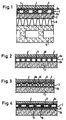
- Fig. 1 shows schematically the structure of a load-bearing, walkable Ceiling construction in cross section.
- the Floor covering 1 for example made of tiles or stone slabs
- the screed layer 2 is for thermal decoupling of the floor coverings from the massive, highly heat conductive Screed layer a double-walled rigid and rigid Insulating body 3 arranged, a continuous, air-filled Includes cavity 4.
- the two cover plates 6a, 6b of the insulating body 3 are with the screed layer 2 or the flooring 1 over an adhesive or mortar layer connected. Run transversely between the cover plates 6a, 6b a variety of rigid support threads 5, but here only schematically and not indicated according to their number are.
- This double-walled insulating body 3 is preferably made of a resin-impregnated textile spacer fabric, that in a known manner from two, by transverse or vertical Web thread structures of interconnected fabric cover layers consists. After an applied one has hardened Resin matrix form this fabric, rigid and rigid sandwich constructions with a free space between the two cover layers.
- Sandwich structures made of textile spacer fabrics of this type are suitable, especially when using glass fiber filaments, because of their exceptional mechanical stiffness and resistance to deformation for thermal separation of two masses lying on top of each other and under load Stratifications, as a result of their transverse thread structures can absorb and transmit high forces. Due the air gap 4 and between the top layers the low mass of the materials making up the plate body make a high quality thermal insulation material is already at a relatively low height compared to Insulation boards made of hard foam or mineral fibers, excellent Provides insulation performance.
- the structure shown in cross section in Fig. 1 load-bearing and walkable ceiling construction also shows explanatory the arranged below the screed layer 2 usual insulation layers 8 made of foam or Fiberboard. Since these plates are not dimensionally stable and are resilient, they must be rigid in themselves load-bearing, solid cement layer or a dimensionally stable Screed layer from 5 to 8 cm floating so to speak become.
- the insulation layer 8 itself is the constructive load-bearing, cast from concrete or from brick Ceiling plate 9 on.
- the ceiling plate 9 thus forms in this embodiment together with the insulation layer 8 and the screed layer 2 is the load-bearing substructure.
- the floor covering 1 at least for solar radiation partially permeable, i.e. transparent or translucent, material formed.
- the floor covering 1 preferably translucent glass tiles or ceramic tiles used in the translucent glass body are embedded.
- the Floor covering 1 with the help of a transparent adhesive connected to the insulating body 3.
- translucent Tiles along with one made from fiberglass textile spacer fabric as an insulating body 3 allows one Use of the floor structure described here according to Art a solar energy trap and enables due to the thermal Decoupling the covering 1 from the heated screed layer 2 with the help of the air gap 4 the storage solar radiation energy into the thermally massive Screed layer 2.
- Wall structure can be the screed layer 2 and the thermal insulation layer 8 omitted.
- the insulating body 3 is here by means of an adhesive bonded to the load-bearing masonry.
- the cover plates 6a, 6b are preferably perforated or drilled to prevent the glue from partially penetrating the cover plates 6a, 6b and thus better adhesion of the Insulating body 3 on the masonry or the surface covering 1 to ensure the insulating body 3.
- Such an inventive Wall construction also allows use one at least partially permeable to solar radiation Surface covering 1.
- Fig. 2 is the air gap 10 through one of the bottom surfaces of the tiles and stone slabs 1 raised embossed line or net-shaped grid 11 brought about. 3 becomes the surface of the textile insulating body 3 trained with knobs 12.
- the screed layer 2 or the lower cover plate 6b facing the screed layer 2 be equipped to reduce emissions.
- the flat cavity 4 facing inner surfaces of the Cover plates and / or the support threads with an emission-reducing Coating, for example by spraying by means of a suitable nozzle tool.
- the equipment of the insulating body 3 with emission-reducing Coatings are more translucent, especially when used Tiles as surface covering 1 advantageous.
- emission-reducing coating (low-E coating) 7 either pyrolytic in the run-up to the curing process of the Applied tiles (at a temperature of approx. 400 - 500 ° C), or on the finished product in a vacuum process be evaporated onto the underside of the tiles. In such a coating is also rational an injection process can be implemented. However, it is preferable a pyrolytically applied coating. It is extraordinary scratch-resistant and resistant to oxidation. These layers can also be used as semiconductor layers as well as metal layers electrically conductive for resistance heating systems be used.
- Low-E coatings can be used for both solar radiation transparent and opaque. At primarily transparent or translucent tiles is therefore, if priority is given to the storage effect in the massive wall structures has to assume more transparent coatings.
- FIGS. 1-3 show an insulating body 3 constructed from two layers 3a, 3b for the thermal decoupling of the screed layer 2 from the floor coverings 1.
- the upper layer 3a of the insulating body 3 is, as described under FIGS. 1-3, made of a hardened resin-coated layer textile spacer fabric formed.
- the lower layer 3b is formed from a single-layer velor-like textile spacer fabric and is adhered to the upper layer 3a via an adhesive layer or already connected to the fabric structure in terms of production technology.
- the adjoining cover layers of the layers 3a and 3b together form the intermediate plate 13.
- the single-layer velor-like textile spacer fabrics used for the lower layer 3b form, after the resin matrix has hardened, row-like, rigid and load-bearing loops 14 arranged vertically on the cover layer, which here are only indicated schematically and extend transversely between the intermediate plate 13 and the screed layer 2.
- an additional stable flat cavity 15 is created between the screed layering and the floor coverings.
- the use of a loop plate body 3b also enables one simple attachment of the insulating body 3 to a wall structure. The attachment to the wall is carried out here with the aid of a layer of mortar or plaster into which the loops 14 are pressed in half, keeping an air-filled cavity 15 free.
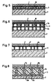
- Fig. 5 shows a floor structure according to the invention in the Insulating body 3 integrated pipes 16 for floor or wall heating systems. It can be copper or plastic pipes, which are from a heat-transferring Fluid flow through. When using more translucent Surface coverings 1 can be used for the heat transfer fluid Excess heat is removed from the solid substructure be used.
- Fig. 6 shows one especially for floor and wall heating suitable floor or wall structure.
- the insulating body 3 consists of two plate bodies or layers 3a and 3b, each consisting of a two-layer textile spacer fabric made and over the each other Adjacent fabric cover layers are bonded together are.
- the plate body receiving the piping system 16 3a goes through to the cold screed or wall side the second plate body 3b thermally insulated.
- This second Plate body 3b can also, corresponding to that in Fig. 4th shown embodiment, made of a velor-like Spacer fabric to be made.
- Advantageously is then the surface of the plate body facing the substructure 3b with an emission-reducing coating.
- the insulating body 3 also line networks for electrical resistance heating inserted or electrical heating foils are inserted.
- the latter can also advantageously between the Flooring and the insulating body in the form of an adhesive film inserted or integrated directly into the floor covering become.
- Fig. 7 shows an insulating body 3, the upper cover layer 6a milled recesses 17 for receiving electrical Has lines and connecting cables.
- Fig. 8 shows an insulating body 3, the flat, air-permeable All or part of the cavity with a foamed Material 18 is filled.
- the insulating body receives an extraordinarily high bending stiffness and shape retention.
- Both the floor coverings 1 and the screed floor 2 have as already shown under Fig. 2 and 3, embossed in a grid raised structures 11a, 11b in order in this way to form an air gap 10a or 10b, the additional Heat transfer resistance generated.
- the at the air gap surfaces adjoining on both sides can then be used for reduction of heat exchange via heat radiation with aluminum foils or low-E layers (not shown here) as in connection with FIGS. 2 and 3 described.
- the embodiment according to FIG. 8 enables due to its high rigidity and surface stability a ceiling structure with screed layers less Thickness.
- the insulating body according to the invention can can also be used directly as load distribution layers.
- such insulating body 3 in an advantageous manner, in particular as a load-distributing Use elements in beamed ceilings.
- You will be below the load-bearing ceiling beams 21 as cladding battens and above as walk-in floor slabs for reception the flooring 1 attached with conventional angle fittings.
- the space between the wooden beams is the usual Foam or fiber insulation 8 filled.
- the insulating body 3 according to Figure 11 to produce in strips or cut accordingly and in parallel at a distance from each other on the substructure, here the screed layer 2, by half the cost of the insulating body material or limit a third.
- Channel structures can then be found both in the form of strips applied insulating body plates 3, as well the spaces 22 between the parallel spaced apart installed insulated body panels realized.
- the strip-shaped insulating body plates 3 are filled in accordance with Figure 8 with a rigid, integral foam off, so you get in the task of channel systems inside of the insulating body a lath-shaped body of great strength and bending stiffness, which, as a slatted frame doweled on the wall surface for efficient application large surfaces can be used.
- the channel structure is then realized solely through the gaps 22.
- Fig. 12 shows the constructive envelope surface structure of a Space.
- the textile hollow plates of the insulating body 3 The wall opens into the hollow panels of the corner area Ceiling envelope.
- the ceiling Insulated body 3 laid from there also in opposite or laterally fitted with hollow panels Open up wall surfaces. Including the floor area, in this way becomes a thermally enveloping space closed cavity system communicating via channel structures realized.
- the room can be heated with underfloor heating or by an integrated in the insulating body plates 3 Hot water or electrically operated baseboard heating 23 be heated (Fig. 13).
- the heat is in the floor area mainly emitted directly to the interior of the room via radiation.
- the insulation to the load-bearing wall is then created by appropriate Design of the back of the insulating body panels, for example through an additional narrow airspace 10b, preferably in conjunction with a low-E layer, such as described in connection with Figures 3 and 8.
- Translucent or partial then have a particularly positive effect translucent surface coverings as they have a large Part of the incoming sun rays and can forward distributed. If this way in the Additional solar energy can occur during the heating season a temperature control the supply through the building heating system generated energy throttled or turned off become.
- the room-enveloping insulating plate system can of course used in this way also in the summer period to excess solar energy record and discharge. But it can also be beneficial Way by feeding in cooled air as a surface cooling system Find application.
- Fig. 14 shows one for the installation of a baseboard heater cross-section of a particularly suitable wall structure according to the invention.
- the textile spacer fabrics are here as Wall cladding used.
- the wall side of the insulator 3 is here again from a single-layer loop plate 3b of the type described in Fig. 4 and adhesive to the Applied to the wall.
- the attachment to the wall is done with the help a layer of mortar or plaster 24, the loops 14 half into this layer, an air-filled cavity 15 keep clear, be pushed in.
- another double wall Plate body 3a may be provided on the single-layer Loop plate 3b is adhesively attached.
- Perforations 25 are provided, which the establishment of a Enable ventilation system.
- the wall structure according to the invention shown here can be advantageous Way with an additional heating function
- a baseboard heater 23 are equipped.
- the Heating energy is applied to the wall element near the floor continuous tubular body arranged in the wall element fed that connected to a hot water heating system are.
- the plate body 3b arranged on the wall which at Embodiment shown here as a single-layer loop plate is designed, forms with the help of the cavity 15 for load-bearing Substructure of the wall element towards a thermal barrier so that the thermal energy supplied to the flat cavity 4 mainly from the room-side covering 1 of the textile Hollow plate body 3a added and towards the room is emitted.
- Wall heating systems can also be advantageously used in this way supply via electrical resistance heaters.
- the heating network can be designed as a baseboard heating system or the lower wall area at the parapet height take in.
- the construction of such electrically heated Systems can alternatively also be used according to the following 15 and 16 embodiments described respectively.
- Tiles for example, can be used as wall coverings, Marble slabs, wooden panels or the usual fabric or Paper wallpapers are used.
- 15 and 16 represent particular embodiments of high efficiency, energy-saving electrical floor and wall heating systems because of the lack of thinner viable It was previously insulation layers with high thermal resistance values not possible to drain thermal energy into the massive Effectively limit floor and wall layers.
- FIG. 15 shows the structure of such a system in use Ceramic flooring 1 made of tiles and stone slabs.
- the heating foils or the heating conductor networks fixed in heating mats 26 are placed directly under the floor covering 1 and with an adhesive layer 27 of high temperature resistance and high flexibility glued. Because of the high Thermal resistance of the textile insulating body 3 and aluminum foil lying between the heating mat and the insulating body or the emission-reducing coating 7a the surface of the insulating body facing the heating mat the heat flow is largely supplied to the floor covering on one side and the space from the stone slabs to heat radiation fed.
- Fig. 16 shows the structure of an electric floor or Wall heating system when using surface coverings 1 with low thermal conductivity, such as in particular Carpet, parquet, PVC and cork coverings.
- the heating foil or Heating plate 26 is assigned a metal plate 28 on the room side, which due to their high thermal conductivity Absorbs heat flow and over the flooring in the room radiates.
- This function can also be performed by a thin storage layer 29 taken over or reinforced by such a layer. It is proposed that a thin, reinforced with a textile fabric 30 screed, gypsum, or cement layer, as shown in FIG. 16. In this way, extremely thin, load-bearing, Manufacture rigid and dimensionally stable plate constructions.
- a heating conductor network can be woven in (in Fig. 16 not shown). In such a case, the heating mat is not required 26 and the metal plate 28. Opposite the load-bearing
- the textile can be used to support the floor or wall structure Insulating body 3 with additional air-filled spaces 10b and an aluminum foil or an emission-reducing Coating 7b as a thermal radiation barrier be shielded.
- FIG. 17 shows a possible wall fastening of the insulating body 3 to a cross batten 34 with the aid of an adhesive connection 31.
- the bond can be done by penetrating the adhesive into predetermined perforations of the wall-side cover plate 6b and subsequent curing of the adhesive mechanically secured become.
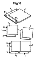
- a laying of tiles according to this shown in Fig. 18 Design ensures a reliable Sealing of the tile subsurface, because they form no gaps running through to the wall or floor substructure out. A tiled outer wall remains secured against driving rain.
- This version also proves to be advantageous for laying work. It helps to better align the surface geometry and in particular for exact compliance the joint width.
- the through holes 33 of the insulating body plates 3 serve each for doweling on the load-bearing wall structures. alternative for this, the tiles can be drilled using these holes Adhesive scraps can be fixed and attached.
- the insulating body plates 3 perforations on one or both sides can be provided that fix or glue favor with the wall structure and with the surface covering. The adhesive then partially penetrates the perforation on.
Landscapes
- Engineering & Computer Science (AREA)
- Architecture (AREA)
- Civil Engineering (AREA)
- Structural Engineering (AREA)
- Physics & Mathematics (AREA)
- Acoustics & Sound (AREA)
- Electromagnetism (AREA)
- Life Sciences & Earth Sciences (AREA)
- Wood Science & Technology (AREA)
- Building Environments (AREA)
- Floor Finish (AREA)
Abstract
Description
Die Erfindung betrifft einen hochwärmedämmend ausgerüsteten Boden-, Decken- oder Wandaufbau, bei dem ein Isolierkörper zwischen einem tragenden Unterbau und einem Oberflächenbelag angeordnet ist.The invention relates to a high thermal insulation Floor, ceiling or wall structure, in which an insulating body between a load-bearing substructure and a surface covering is arranged.
Bei der Erstellung von Wohn- und Bürogebäuden, von Werkhallen und Zweckbauten gewinnt die Einrichtung eines thermisch behaglichen sowie hygienisch zuträglichen Raumklimas zunehmend an Bedeutung. Dafür ist es notwendig, die Temperatur der Hüllflächen des Raums möglichst an die der Raumluft anzugleichen. Bereits eine um 2 Kelvin von der Raumlufttemperatur abweichende kältere Wandflächentemperatur führt zumindest in Wandnähe zu thermischem Mißbehagen.When creating residential and office buildings, workshops and functional buildings wins the establishment of a thermal comfortable and hygienically beneficial indoor climate increasingly in importance. For this it is necessary to change the temperature of the envelope surfaces of the room as close as possible to that of the room air. Already one by 2 Kelvin from the room air temperature deviating colder wall surface temperature leads at least near the wall to thermal malaise.
Üblicherweise führt der Mensch über 50 % seiner Körperwärme durch den Strahlungsaustausch mit den ihn umgebenden Raumhüllflächen ab. Den einseitig zu kälteren Wänden gerichteten Wärmeentzug empfindet er als Störung seiner Körperwärmebilanz. Man spricht dann von einem im Raum vorherrschenden asymmetrischen Strahlungsklima.Usually people carry over 50% of their body heat through the exchange of radiation with the surrounding envelope from. The one-sided facing colder walls He perceives heat withdrawal as a disturbance of his body heat balance. One then speaks of one prevailing in the room asymmetrical radiation climate.
Als unbehaglich empfunden werden außerdem die an kälteren Wänden stets entstehenden, nach unten gerichteten konvektiven Raltluftströmungen, die sich am Fußboden haftend raumwärts fortpflanzen. Dieses Phänomen ist allgemein bekannt und tritt insbesondere an Fensterfronten auf, die infolge höherer Wärmedurchgangswerte gegenüber den übrigen Wandflächen immer geringere Oberflächentemperaturen aufweisen. Dies führt dazu, daß beispielsweise in mit einscheibigen Verglasungen ausgerüsteten Altbauten der Fensternahraum zur Winterzeit unbehaglich und nahezu unbewohnbar ist.The colder ones are also perceived as uncomfortable Walls always emerging, downward convective Cold air currents adhering to the floor towards the room procreate. This phenomenon is well known and occurs particularly on window fronts that result from higher heat transfer values compared to the other wall surfaces have ever lower surface temperatures. This leads to, for example, in with single-pane glazing equipped old buildings the window habitat at winter time is uncomfortable and almost uninhabitable.
Die Behaglichkeit störende Einflüsse können aber nicht nur von kalten Wandflächen, sondern auch von dem zur Hüllfläche des Raums gehörenden Fußboden ausgehen. Man spricht hier von fußkalten Räumen trotz einer für das Wohlbefinden ausreichenden Raumlufttemperierung. Bei Fußböden bedarf es gegenüber den vertikalen Wandflächen sogar eines höheren Maßes an Wärmedämmung, um ein der Raumluft angeglichenes Temperaturniveau des Bodens zu erreichen. Dies liegt daran, daß der Mensch im stehenden Zustand fast 30 % seiner Körperwärme über die Fußflächen abgibt, da in diesem Falle durch den hohen Flächendruck der Wärmeaustausch mit der Bodenfläche unmittelbar über die Wärmeleitung und ohne einen zwischen den Austauschflächen liegenden, den Wärmeaustausch mindernden Wärmeübergangswiderstand erfolgt.However, influences that disrupt comfort can not only from cold wall surfaces, but also from that to the envelope surface floor belonging to the room. One speaks here of cold rooms despite a sufficient for the well-being Raumlufttemperierung. With floors it is necessary the vertical wall surfaces even to a higher degree Thermal insulation at a temperature level that matches the indoor air to reach the ground. This is because the People standing almost 30% of their body heat emits on the foot surfaces, because in this case by the high surface pressure of heat exchange with the floor surface directly via heat conduction and without an between the exchange surfaces, reducing the heat exchange Heat transfer resistance takes place.
Im Falle von Steinböden oder mit Fliesen ausgelegten Badezimmerböden erreicht die Wärmeabfuhr wegen der hohen Dichte des Steinzeugs sowie der hohen Wärmeleitfähigkeit dieses Materials ein extrem hohes Maß, zumal wenn die keramischen Platten unmittelbar und ungedämmt auf Zementböden aufliegen. Auch bei gekachelten Wänden ist der Wärmeentzug besonders stark, da die Wandflächen stets auf einem Temperaturniveau unterhalb der Raumluft verbleiben und dann nicht nur die auf dem Strahlungsaustausch beruhenden Behaglichkeitseinbußen provozieren, sondern außerdem noch Kondenswasserbeschläge ausbilden, die zusätzlich Verdunstungskälte erzeugen.In the case of stone floors or tiled bathroom floors achieves heat dissipation due to the high density stoneware and its high thermal conductivity Materials an extremely high degree, especially if the ceramic Place the boards directly and uninsulated on cement floors. Heat extraction is also special with tiled walls strong because the wall surfaces are always at a temperature level remain below the room air and then not only those on loss of comfort due to radiation exchange provoke, but also condensation water fittings train who also generate evaporative cooling.
Entsprechend der üblichen Bauausführung werden Bodenbeläge, wie feinkeramische Fliesen, keramische Spaltplatten, Bodenklinkerplatten, PVC-, Gummi- oder Korkplatten, aber auch Holzparkett- und textile Beläge in aller Regel auf mindestens 5 bis 8 cm dicken Zement-Estrichschichten aufgebracht. Im Falle keramischer Fliesen und Steinzeugplatten erfolgt die Verlegung zusätzlich in einem auf den Estrichschichten aufgebrachten 1 bis 2 cm dicken Mörtelbett. Die Bodenbeläge grenzen also unmittelbar an voluminöse, massive Materialschichten mit hoher thermischer Masse, die eine hohe Wärmeleitfähigkeit und eine große Wärmeeindringzahl aufweisen. Die Folge davon ist, daß Fußbodenbeläge, mit Ausnahme von dickdimensionierten Korkbelägen sowie hochflorigen Teppichböden, stets als fußkalt gelten. Sie stehen den Forderungen nach einem behaglichen Raumklima wegen der intensiven Wärmeableitung an den massiven, konstruktiv tragenden und Lasten aufnehmenden Fußbodenunterbau entgegen.According to the usual construction, floor coverings, such as fine ceramic tiles, ceramic split tiles, floor clinker tiles, PVC, rubber or cork boards, but also Wood parquet and textile coverings usually at least 5 to 8 cm thick cement screed layers applied. In the case of ceramic tiles and stoneware slabs laying additionally in one on the screed layers applied 1 to 2 cm thick mortar bed. The flooring thus directly border on voluminous, massive layers of material with high thermal mass, which has high thermal conductivity and have a large heat penetration number. The consequence of this is that floor coverings, with the exception of thick cork coverings and deep-pile carpets, always count as cold feet. They are up to the demands after a comfortable room climate due to the intensive heat dissipation on the massive, constructively bearing and loads receiving floor substructure.
Dies trifft auch dann zu, wenn der Boden- oder Deckenaufbau, wie üblich, unterhalb der Estrichschicht eine ausreichende Wärmedämmschicht enthält, denn in erster Linie ist das Wärmeempfinden beim Stehen und Gehen auf Fußböden von der Temperatur der Kontaktfläche, also der Temperatur der Fußbodenoberfläche, abhängig. Eine den eigentlichen Wärme- und Schalldämmschichten aufliegende Estrichschicht, die wiederum als Unterbau für den eigentlichen Fußbodenbelag dient, findet man bei begehbaren und gedämmten Deckenkonstruktionen als in sich steife, selbsttragende und Lasten aufnehmende Schicht stets vor.This also applies if the floor or ceiling structure, as usual, sufficient under the screed layer Contains heat insulation layer, because the first thing is the sensation of heat when standing and walking on floors by temperature the contact surface, i.e. the temperature of the floor surface, dependent. The actual heat and Soundproofing layers on the screed layer, which in turn serves as a substructure for the actual floor covering one with walkable and insulated ceiling constructions as rigid, self-supporting and load-bearing Always shift before.
Untersuchungen von Oberflächentemperaturen von Fußbodenbelägen verschiedener Art, die einer etwa 5 cm dicken Estrichschicht auflagen, führten infolge der Wärmeableitung an die Estrichmasse zu thermisch bedenklichen Ergebnissen. Beim Aufsetzen des unbekleideten Fußes auf Steinzeugplatten sinkt die Körpertemperatur des Fußes an der Berührungsfläche schnell ab. Die Abkühlung erreicht nach wenigen Minuten bereits Differenzwerte von über 10 Kelvin. Kunststoffbeläge können die Wärmeableitung nur wenig verzögern. Auch Parkettbeläge aus Hartholz führen zu fußkalten Böden. Befriedigende Ergebnisse lassen sich mit hochflorigen Teppichböden erzielen. Erst übermäßige Raumluftaufheizungen lassen bei den zuerst genannten Belägen ein behaglichen Fußbodenklima aufkommen, das sich aber erst mit einer gewissen zeitlichen Verzögerung einstellt.Investigation of surface temperatures of floor coverings of various types, that of an approximately 5 cm thick screed layer requirements, led to the Screed compound for thermally questionable results. At the Placing the bare foot on stoneware slabs drops the body temperature of the foot at the contact surface quickly. The cooling down already takes a few minutes Differential values of over 10 Kelvin. Plastic coverings can only slightly delay heat dissipation. Also parquet flooring hardwood leads to cold floors. satisfactory Results can be achieved with deep-pile carpets. Only excessive room air heating can leave the a comfortable floor climate arise but that only takes a certain time Delay sets.
Zusätzlich zu der starken Wärmeableitung an die massiven Estrichschichten wird dem Fußboden im Falle untertemperierter Wandstrukturen durch die dann entstehenden bodennahen Kaltluftströmungen konvektiv Wärme entzogen. In addition to the strong heat dissipation to the massive Screed layers are the floor in the case of hypothermic Wall structures through the resulting ground level Cold air flows extract heat convectively.
Bisher war es, von Fußboden-Heizsystemen einmal abgesehen, bautechnisch kaum möglich, ein annähernd ausgeglichenes vertikales Raumtemperaturprofil zu gewährleisten. Die üblicherweise zur Wärmedämmung von Raumhüllflächen verwendeten Faser-, Schaum- und Perlit-Dämmstoffe leiten ihre Funktion aus der Vielzahl kleinster Lufteinschlüsse und einer Vielzahl von Reflexionsflächen an ungeordneten dünnwandigen Wandstrukturen bzw. an unverbundenen Faden- und Kornstrukturen ab. Sie können daher im Bodenaufbau, wie dies in der Baupraxis auch geschieht, nur unterhalb von tragfähigen, lastaufnehmenden Beschichtungen verwendet werden, also nur dann, wenn ihnen flächenhaft eine aushärtende, biegesteife und sich selbsttragende Schichtung aufliegt, die das Volumen des Dämm-Materials nicht zusammendrückt.So far, apart from underfloor heating systems, hardly possible in terms of construction, an almost balanced one to ensure vertical room temperature profile. The usual used for thermal insulation of room envelopes Fiber, foam and pearlite insulation materials guide their function from the multitude of smallest air pockets and a multitude from reflective surfaces to disordered thin-walled ones Wall structures or on unconnected thread and grain structures from. You can therefore in the floor structure, like this in the Building practice also happens only below viable, load-bearing coatings are used, so only then when they have an area-hardening, rigid and self-supporting stratification rests on top of the volume of the insulation material does not compress.
Bereits die Stoffeigenschaften der bisher verwendeten Dämm-Materalien stehen also Forderungen nach eigenständiger Steifigkeit und Tragfähigkeit sowie Formhaltigkeit bei Belastung entgegen. Die thermische Trägheit der dann auf den herkömmlichen Dämm-Materialien notwendigerweise aufliegenden tragfähigen Schichten ist aber - wie oben dargelegt - gerade die Ursache für ein unzulängliches Raumklima.Already the material properties of the insulation materials used so far there are demands for independent rigidity and load-bearing capacity and shape retention under load opposite. The thermal inertia then on the conventional Insulation materials necessarily support load-bearing materials However, as explained above, stratification is precisely that Cause of an inadequate indoor climate.
EP O 428 201 beschreibt Überbrückungstäden in einer dümen Verbindungschicht, wobei Schwerkräfte kompensiert werden sollen. Ein Isolierkörper ist in EP O 428 201 nicht angesprachen.EP 0 428 201 describes bridging threads in a dense connecting layer, whereby gravitational forces are to be compensated for. An insulating body is not addressed in EP O 428 201.
Aufgabe der Erfindung ist es daher, die bestehenden thermischen Mängel von Boden- oder Deckenaufbauten, insbesondere bei Aufbauten mit Keramik- und Steinzeugbelägen, sowie die gleichen Mängel bei Wandaufbauten mit unzureichender Eigendämmung zu beheben, um so die Behaglichkeit von Räumen durch Angleichung der Oberflächentemperaturen ihrer Hüllflächen zu erhöhen.The object of the invention is therefore the existing thermal Defects in floor or ceiling structures, in particular for structures with ceramic and stoneware coverings, as well as the same defects in wall structures with insufficient self-insulation to fix so as to make the rooms comfortable Alignment of the surface temperatures of their envelope surfaces increase.
Gemäß der Erfindung wird ein Boden-, Decken- oder Wandaufbau gemäß den Merkmalen des Anspruchs 1 bereitgestellt. Ein Isolierkörper in zwischen einem konstruktiv tragenden Unterbau und einem Oberflächenbelag angeordnet. Als Unterbau wird dabei jede herkömmliche, einem Wand- oder Bodenbelag unterlegte Schichtung angesehen. Der Belag kann beispielsweise aus keramischen Fliesen, Steinzeugplatten, Kunststoffplatten, Holzparkett oder auch Teppichböden bestehen. Im Falle von Wandbelägen kann der -Belag neben den vorgenannten Materialien auch Tapeten oder einen einfachen Farbanstrich umfassen. Der erfindungsgemäße Boden-, Decken- oder Wandaufbau ist dadurch gekennzeichnet, daß der Isolierkörper durch eine Vielzahl von quer zwischen dem Oberflächenbelag und dem Unterbau verlaufenden, biegesteifen Stützfäden gebildet ist, die zur thermischen Entkopplung des Unterbaus von dem Belag zwischen diesen einen flächigen und formhaltigen Hohlraum aufspannen.According to the invention, a floor, ceiling or wall structure according to the features of claim 1 provided. An insulating body in between one structurally load-bearing substructure and a surface covering arranged. Any conventional, layering underlaid on a wall or floor covering. The covering can, for example, be made of ceramic tiles, Stoneware panels, plastic panels, wooden parquet or also Carpets exist. In the case of wall coverings, in addition to the aforementioned materials, the covering can also be wallpaper or include a simple coat of paint. The invention Floor, ceiling or wall structure is characterized by that the insulating body through a variety of cross between the surface covering and the substructure, rigid Support threads are formed, which are used for thermal decoupling the substructure of the covering between these one Cover the flat and shape-retaining cavity.
Vorzugsweise ist der Oberflächenbelag für solare Strahlung wenigstens teilweise durchlässig, d.h. transparent oder transluzent.The surface covering is preferably for solar radiation at least partially permeable, i.e. transparent or translucent.
Eine geeignete Maßnahme zur wirksamen Minderung des Wärmeübergangs zwischen zwei aufeinandergefügten, hochwärmeleitenden Feststoffkörpern ist die Einlagerung einer ruhenden, konvektionsarmen Luftschicht zwischen diesen Festkörpern zur Entkopplung des Wärmeaustausches. Das verfolgte Prinzip besteht somit darin, die Boden-, Decken- oder Wandbeläge thermisch von ihren Tragschichten durch einen Isolierkörper zu entkoppeln, der zwischen den Belägen und ihren Tragschichten lediglich einen flächigen und formhaltigen Hohlraum aufspannt. Dazu bedarf es hier der Bereitstellung eines leistungsfähigen Wärmedämmstoffs mit hinreichend eigenständiger Flächenstabilität, Steifigkeit und Tragfähigkeit, der als konstruktives Material selbst Kräfte aufnehmen und übertragen kann.A suitable measure to effectively reduce heat transfer between two superimposed, highly thermally conductive Solid bodies is the storage of a dormant, low convection air layer between these solids for Decoupling the heat exchange. That haunted Principle is therefore the floor, ceiling or Wall coverings thermally from their base layers through a Isolate the insulating body between the coverings and their base layers are only flat and form-retaining Open the cavity. This requires the provision here a powerful thermal insulation material with sufficient independent surface stability, rigidity and Load capacity, which as a constructive material itself forces can record and transmit.
Der Isolierkörper ist daher durch eine Vielzahl von quer zwischen dem Oberflächenbelag und dem Unterbau verlaufenden, biegesteifen Stützfäden gebildet. Zur thermischen Entkopplung des Unterbaus von dem Belag spannt der Isolierkörper zwischen diesen einen flächigen, formhaltigen Hohlraum auf. Der Hohlraum ist vorzugsweise luftgefüllt, kann aber auch eine üblicherweise zur Wärmedämmung verwendete Kunststoffschaummasse enthalten. Bei Verwendung von für solare Strahlung durchlässigen oder teildurchlässigen Oberflächenbelägen kann der Hohlraum eine Füllung mit einem transluzenten Material geringer Wärmeleitfähigkeit, wie beispielsweise einen Silica-Aerogel-Strukturstoff, aufweisen.The insulator is therefore by a variety from across between the surface covering and the substructure extending, rigid support threads formed. For thermal Decoupling the substructure from the covering spans the Insulating body between these a flat, form-retaining Cavity on. The cavity is preferably filled with air, but can also be a commonly used for thermal insulation Plastic foam mass included. When using for solar radiation permeable or partially transparent surface coverings the cavity can be filled with a translucent material with low thermal conductivity, such as have a silica airgel structure.
Der hier vorgeschlagene Dämmstoff ist in der Lage, die auf die Bodenbeläge einwirkenden Traglasten über große Flächen ohne eigene Formveränderung, beispielsweise auf den schwimmenden Estrich als Unterbau, zu übertragen, bzw. bei Wandbelägen die hier einwirkenden Traglasten aufzunehmen. Die Tragfähigkeit beruht auf der Verstrebungswirkung der Vielzahl von im wesentlichen axial belasteten Stützfäden. Trotz dieser Vielzahl von Fäden, besitzen diese einen kleineren Flächenanteil als herkömmliche Verstrebungen und beugen daher der Entstehung von Kältebrücken vor. Zusammen mit der in den Hohlraum eingelagerten Luftschicht führt die Fadenstruktur des Isolierkörpers dazu, daß der auf Konvektion beruhende Wärmeaustausch zwischen dem Belag und dem tragenden Unterbau fast vollständig eliminiert wird.The insulation material proposed here is able to loads acting on floor coverings over large areas without changing its shape, for example on the floating one Screed as a substructure, to be transferred or for wall coverings to take the loads acting here. The Load capacity is based on the bracing effect of the multitude of essentially axially loaded support threads. Despite of this multitude of threads, these have a smaller one Proportion of area than conventional struts and bend hence the formation of cold bridges. Together with the The thread structure leads into the air layer embedded in the cavity of the insulator so that the convection based heat exchange between the covering and the load-bearing Substructure is almost completely eliminated.
Die Stützfäden des Isolierkörpers sind vorzugsweise aus anorganischen Fasern, wie Glas-, Keramik-, Kunststoff- oder Kohlefasern, gebildet. Darüber hinaus können aber auch organische Fasern und insbesondere biologische Fasern oder Naturfasern Anwendung finden, wie z.B. Fasern aus Hanf oder anderen pflanzlichen Produkten. Die Stützfäden weisen bevorzugt eine mittlere Feinheit im Bereich von etwa 20 bis 80 tex auf und sind in einer Dichte von zwischen etwa 10 bis etwa 60 Fäden/cm2 angeordnet. Ein solcher Isolierkörper besitzt hervorragende Wärmedämmeigenschaften, da eine Wärmeübertragung durch Wärmeleitung durch die Verwendung von leichten Werkstoffen mit geringem Eigenvolumen, sowie die geringe Masse der hier äußerst dünn ausgebildeten, gleichwohl lastaufnehmenden und kraftübertragenden Stützfäden praktisch ausgeschaltet wird. Die hohe Festigkeit und Biegesteifigkeit des Isolierkörpers läßt sich noch dadurch erhöhen, daß die Stützfäden einander kreuzend angeordnet sind. Durch den damit verbundenen Triangulierungseffekt wird eine insgesamt formsteife Verstrebung erreicht.The support threads of the insulating body are preferably formed from inorganic fibers, such as glass, ceramic, plastic or carbon fibers. In addition, organic fibers and in particular biological fibers or natural fibers can also be used, such as fibers made from hemp or other vegetable products. The support threads preferably have an average fineness in the range from approximately 20 to 80 tex and are arranged in a density of between approximately 10 to approximately 60 threads / cm 2 . Such an insulating body has excellent thermal insulation properties, since heat transfer by heat conduction is practically eliminated by the use of lightweight materials with a small internal volume, as well as the low mass of the extremely thin, yet load-bearing and force-transmitting support threads. The high strength and bending stiffness of the insulating body can be further increased in that the supporting threads are arranged crossing one another. The triangulation effect associated with this leads to an overall rigid bracing.
Bei einer bevorzugten Ausführungsform weist der Isolierkörper eine obere und/oder eine untere Deckplatte auf, wobei die obere Deckplatte mit dem Belag und die untere Deckplatte mit dem Unterbau verbunden ist. In diesem Fall ist eine besonders einfache Herstellung des erfindungsgemäßen Bodenoder Wandaufbaus gewährleistet. Der Isolierkörper kann ferner noch eine oder mehrere Zwischenplatten aufweisen, wobei die Zwischenplatten dann über die Stützfäden miteinander bzw. mit der oberen und/oder der unteren Deckplatte verbunden sind. In einem solchen Fall ist der Isolierkörper aus zwei oder mehr Schichten gebildet, wobei die einzelnen Schichten selbst nach Art eines einschichtigen Isolierkörpers aufgebaut sind.In a preferred embodiment, the insulating body an upper and / or a lower cover plate, wherein the upper cover plate with the covering and the lower cover plate is connected to the substructure. In this case it is particularly simple manufacture of the soil or Wall structure guaranteed. The insulating body can also still have one or more intermediate plates, wherein the intermediate plates then over the support threads together or connected to the upper and / or lower cover plate are. In such a case, the insulating body is off two or more layers are formed, the individual Layers even in the manner of a single-layer insulating body are built up.
In vorteilhafter Weise wird ein solcher Isolierkörper aus einem textilen Abstandsgewebe oder -gewirk durch Imprägnieren mit einem Harz und Aushärten der so erhaltenen Sandwichkonstruktion gebildet, wie dies im Prinzip aus der deutschen Offenlegungsschrift DE 37 23 681 A1 bekannt ist. Darin ist die Herstellung von textilen Abstandsgeweben und -gewirken, sowie deren Verwendung zur Bildung von formsteifen, sandwichartigen Bauteilen beschrieben. In der Technik werden die Abstandsgewebe und -gewirke üblicherweise als Distanzschichten zur Herstellung verschiedener Faserverbundwerkstoffe verwendet.Such an insulating body is advantageously made of a textile spacer fabric or knitted fabric by impregnation with a resin and curing the sandwich construction thus obtained formed like this in principle from the German Publication DE 37 23 681 A1 is known. In this is the production of textile spacer fabrics and knitted fabrics, as well as their use to form rigid, described sandwich-like components. In technology the spacer fabrics and knitted fabrics usually as spacer layers for the production of various fiber composite materials used.
Die zu verwendenden Abstandsgewebe bestehen im allgemeinen aus Decklagen eines textilen Materials, insbesondere aus Keramik-, Glas-, Kunststoff- oder Kohlenstofffasern, oder aus Mischungen solcher Materialien. Die Decklagen sind durch senkrecht oder winklig einlaufende Fäden, sogenannte Stegfäden, miteinander verbunden. Die Stegfäden sind vorzugsweise verdrillt angeordnet und halten gerüstartig die beiden Gewebelagen auf Abstand. Dabei bilden sie in Form einer Schlaufen- oder Maschenstruktur im wesentlichen senkrecht auf den Decklagen stehende Stegreihen aus, wobei die Decklagen miteinander zusätzlich noch durch diagonal zu den Stegreihen verlaufende Fadenstrukturen verknüpft werden können.The spacer fabrics to be used exist generally from cover layers of a textile material, in particular made of ceramic, glass, plastic or carbon fibers, or from mixtures of such materials. The top layers are caused by threads entering vertically or at an angle, so-called web threads, connected to each other. The bridge threads are preferably twisted and hold scaffold the two fabric layers at a distance. In doing so, they form in the form of a loop or mesh structure essentially rows of bars standing vertically on the cover layers, whereby the top layers are additionally diagonally Thread structures running to the rows of webs linked can be.
Bei ihrer Verarbeitung werden die Abstandsgewebe und -gewirke üblicherweise mit Harz getränkt bzw. imprägniert. Das überschüssige Harz wird anschließend zwischen Folien oder Walzen ausgepreßt. Nach der Imprägnierung richten sich die Stegfäden aufgrund der durch die Materialeigenschaften und die Bindungsstruktur erzeugten Rückstellkräfte ohne Hilfsmittel selbständig wieder in ihre ursprüngliche Höhe auf und ermöglichen durch ihre definierbare Länge kalibrierende Abstände zu den Decklagen. Die Festigkeit der nach Aushärtung der Harzschlichten entstehenden Sandwichkonstruktion wird im wesentlichen durch die Anordnung und die Höhe der Stegfäden bestimmt.The spacer fabrics and knitted fabrics are used in their processing usually soaked or impregnated with resin. The Excess resin is then between foils or Rolls pressed out. They depend on the impregnation Bridge threads due to the material properties and the binding structure generated restoring forces without tools back to its original height and enable calibrating distances due to their definable length to the top layers. The strength of after curing The sandwich construction resulting from resin sizes is used in essentially by the arrangement and the height of the web threads certainly.
Bekannt ist auch die Verwendung von sogenannten Rowings-Garnen zum Aufbau von dreidimensionalen textilen Plattenstrukturen, insbesondere solchen mit Abständen von über 12 mm zwischen den Decklagen. Rowings-Garne sind Garne aus endlos gezogenen dickeren Glasfäden. Sie haben zwar nicht die Fähigkeit, sich beim Aushärtungsprozess nach der Harzbenetzung aufgrund des eigenen Dralls selbst aufzurichten, jedoch sind aus diesem Material gefertigte Abstandsgewebe kostengünstiger. Der Aufrichtungsprozess gelingt hier durch ein mechanisches Auseinanderziehen der Decklagen vor dem endgültigen Aushärten der Harzmatrix.The use of so-called Rowings yarns is also known for the construction of three-dimensional textile plate structures, especially those with distances of over 12 mm between the top layers. Rowings yarns are made of yarn endlessly drawn thicker glass threads. You don't have the ability to engage in the curing process after resin wetting to erect yourself due to your own twist, however, spacer fabrics are made from this material cost-effective. The erection process succeeds here a mechanical pulling apart of the top layers before final curing of the resin matrix.
Gegenstand der Erfindung ist daher auch die Verwendung solcher textilen Abstandsgewebe oder -gewirke gemäß den Merkmalen des Anspruchs 36. Die Verwendung betrifft den Aufbau von hochwärmegedämmten Raumhüllstrukturen, also Fußböden, Decken oder Wänden, und insbesondere in Form großflächiger Verlegeplatten vorgefertigte Isolierplattenkörper, die aus den harzimprägnierten und ausgehärteten Abstandsgeweben gebildet sind.The invention therefore also relates to the use of such spacer fabrics or knitted fabrics according to the features of claim 36. The use relates to the construction of highly thermally insulated room envelope structures, i.e. floors, ceilings or walls, and especially in shape Pre-fabricated insulating board bodies with large areas, those made of resin-impregnated and hardened Spacer fabrics are formed.
Für die Zwecke der Erfindung kann ferner ein einlagiges, veloursartig gefertigtes Abstandsgewebe Anwendung finden. Ein aus einem solchen Gewebe durch Imprägnieren mit Harzen und anschließendem Aushärten der Harzmatrix hergestellter Isolierkörper besitzt nur eine Deckplatte, auf der im wesentlichen senkrecht auf der Platte stehende Schlaufen- oder Maschenstrukturen in Reihen angeordnet sind.For the purposes of the invention, a single-layer, Use velvet-like spacer fabrics. One made from such a fabric by impregnating with resins and then curing the resin matrix Insulating body has only one cover plate on which Loop or mesh structures are arranged in rows essentially perpendicular to the plate.
Die Verwendung der textilen Abstandsgewebe oder -gewirke als Dämm-Medien in Form von flächigen, luftgefüllten Plattenkörpern hat unter anderem den Vorteil, daß bereits bei relativ geringen Dickenabmessungen infolge ruhender Luftschichten sowohl geringe Wärmeleitzahlen als auch, bedingt durch die Plattenstruktur, zusätzlich ein Übergangswiderstand gewährleistet wird. Die Wärmeleitfähigkeit λ von Luftschichten liegt mit ca. 0,02 W/mK unter den Werten üblicher Dämmstoffe. Diese Eigenschaft von Luftschichten wird in ähnlicher Weise bereits bei Isolierglaselementen ausgenutzt. Ein luftgefüllter flächiger Hohlkörper ermöglicht zudem die Ausrüstung mit Wärmestrahlungsbarrieren durch Einlage von emissionsmindernden Folien oder Low-E-Beschichtungen.The use of textile spacer fabrics or knitted fabrics as Insulation media in the form of flat, air-filled panel bodies has the advantage, among other things, that already at relative small thickness dimensions due to static air layers both low thermal conductivity and due to the Plate structure, additional contact resistance guaranteed becomes. The thermal conductivity λ of air layers with approx. 0.02 W / mK is below the values of common insulation materials. This property of air layers becomes more similar Way already used in insulating glass elements. An air-filled flat hollow body also enables the equipment with heat radiation barriers by inserting emission-reducing Foils or low-E coatings.
Die thermische Entkopplung der Boden- oder Wandbeläge von den massigen Schichten des Fußbodenunterbaus bzw. von dem tragenden Mauerwerk der Raumwandungen durch einen vorzugsweise doppelwandigen, biege- und formsteifen Plattenkörper, der einen durchgehenden flächigen Hohlraum ausbildet, bietet auch den Vorteil, daß durch entsprechende Ausbildung und Anordnung der Stützfäden oder durch Integration von Rohrleitungen in den Isolierkörper quasi kanalförmige Innenstrukturen eingerichet werden können, die es ermöglichen, den flächigen Isolierkörper nicht nur als passiven Wärmedämmstoff, sondern auch als ein für Wärmeträger leitendes, aktiv zu betreibendes Wärmedämmsystem, beispielsweise als Fußboden- bzw. Wandheizungssystem in der Weise eines Holokausten-Systems, zu nutzen.The thermal decoupling of floor or wall coverings from the massive layers of the substructure of the floor load-bearing masonry of the room walls by a preferably double-walled, rigid and rigid plate body, which forms a continuous flat cavity also the advantage that through appropriate training and Arrangement of the support threads or by integrating pipelines quasi channel-shaped inner structures in the insulating body can be set up that allow the flat insulating body not only as a passive thermal insulation material, but also as a conductive for heat transfer, active thermal insulation system, for example as Floor or wall heating system in the manner of a holocaust system, to use.
Bisher verwendete Plattengerüste mit wabenförmig ausgebildeten Wandstrukturen als versteifende Abstandshalter bieten diesen Vorteil nicht. Die Wabenstrukturen bilden im Plattenkörper keine flächenhaft durchgängigen Hohlräume aus, sondern nur eine Vielzahl voneinander getrennter Kleinsträume. Die erfindungsgemäßen doppelwandigen textilen Plattenkörper dagegen, deren Deckplatten durch abstandgebende, in Reihen angeordnete Stegfäden miteinander versteifend verbunden sind und dadurch geordnete, im wesentlichen kanalförmige Strukturen ausbilden, lassen sich sowohl als ein mit Warmluft oder mit einem wärmeübertragenden Fluid zu beschickendes Wärmeverteilungssystem, aber auch als ein System großflächiger Wärmekonvektoren darstellen.Plate frameworks used so far with honeycomb-shaped Offer wall structures as stiffening spacers not this advantage. The honeycomb structures form in the panel body no flat, continuous cavities, but just a multitude of separate small dreams. The double-walled textile plate body according to the invention contrast, whose cover plates by spacing, in rows arranged web threads are stiffened together and thereby ordered, essentially channel-shaped structures train, can be both as one with warm air or heat distribution system to be charged with a heat transfer fluid, but also as a large-scale system Represent heat convectors.
In vorteilhafter Weise können die durchgängig miteinander verbundenen Plattenkörper bei sommerlicher Übererwärmung der Räume auch als flächendeckendes Kühl- und Lüftungssystem genutzt werden, und zwar in der Weise, daß Kaltluft oder das wärmeübertragende Fluid in einem geschlossenen Kreislaufsystem zirkulierend die Wärme von den Boden- oder Wandplatten abführt. Dabei werden die Nachteile heute gebräuchlicher Kühlanlagen vermieden, die unmittelbar Kaltluft in den Raum einströmen lassen und dadurch oft als unzuträglich empfundene, konvektive Luftströmungen verursachen. Diese Kühlanlagen werden insbesondere auch wegen ihrer hygienischen Problematik kritisiert. Abgesehen von der unvermeidbaren Staubaufwirbelung werden sie von Medizinerseite wegen der Gefahr des Einschleppens und der Übertragung von Krankheitskeimen als bedenklich angesehen.Advantageously, they can be used together connected plate body in summer overheating of the rooms also as a comprehensive cooling and ventilation system are used, in such a way that cold air or heat transfer fluid in a closed circulatory system circulating the heat from the floor or wall panels dissipates. The disadvantages are becoming more common today Cooling systems avoided the immediate cold air in the room let it flow in and thus often perceived as cause convective air currents. These cooling systems especially because of their hygienic problems criticized. Except for the inevitable raising of dust are they given by the medical side because of the danger of Introduction and transmission of disease germs as considered questionable.
Im Falle des Betriebs einer Raumklimatisierung über ein flächig ausgelegtes geschlossenes System von Boden- und Wandhohlplatten gemäß der Erfindung erfolgt die Raumkühlung nicht über konvektive Luftumwälzung. Vielmehr wird durch Absenkung der Oberflächentemperaturen der Raumhüllflächen der Mensch in die Lage versetzt, seinen Wärmeüberschuß durch Strahlungsaustausch über diese gekühlten Flächen abzuführen. In gleicher Weise wie bei einem durch Wärmestrahlung beheizten Raum wird auch hier durch Strahlungsaustausch ein als behaglich empfundenes Raumklima erzeugt. Bei Führung des Kühlmediums in einem umlaufend geschlossenen Kanalsystem, analog einer Fußbodenheizung, bedarf es innerhalb des Raums weder eines Luftaustausches noch der Zuführung von Kaltluft. Die nicht zuträglichen Staubaufwirbelungen entfallen gleichermaßen wie die Ausbreitung von Krankheitskeimen.In the case of operation of a room air conditioning over an area designed closed system of floor and wall hollow panels According to the invention, the room is cooled not about convective air circulation. Rather, through Lowering the surface temperatures of the room envelope man is able to use his excess heat through Dissipate radiation exchange over these cooled surfaces. In the same way as for a heated by heat radiation Here, too, space is transformed into an exchange of radiation creates a comfortable indoor climate. When managing the Cooling medium in a circumferentially closed channel system, Analogous to underfloor heating, it is required inside the room neither an air exchange nor the supply of cold air. The unacceptable swirling of dust is also eliminated like the spread of disease germs.
Der erfindungsgemäße Raumhüllflächenaufbau, der ein den Boden-, Wand- und/oder Deckenbelägen unterlegtes flächiges Hohlplattensystem mit kanalartigen Innenstrukturen vorsieht, kann in vorteilhafter Weise auch zur effizienteren Nutzung der in den Raum einfallenden solaren Strahlungsenergie für die Raumaufheizung nach einem bisher noch nicht bekannten und praktizierten Konzept zur Erzielung höherer Speicherungsquoten in den Wandstrukturen sinnvolle Anwendung finden.The space envelope structure according to the invention, the one Flat, underlaid floor, wall and / or ceiling coverings Provides hollow plate system with channel-like inner structures, can advantageously also for more efficient use the solar radiation energy incident on the room for the room heating after a previously unknown and practiced concept to achieve higher storage rates find meaningful application in the wall structures.
In Anbetracht der im modernen Wohn- und Bürobau gegebenen Trends zu großflächigen Fensterverglasungen mit geringeren Wärmedurchgangsverlusten auch der übrigen Raumhüllflächen, stellt die Überwärmung der Räume durch die einfallende solare Energiestrahlung, bei südlich orientierten Räumen bereits an milden Wintertagen, sonst vorwiegend in den Übergangsmonaten, zunehmend ein tagsüber die Behaglichkeit einschränkendes Problem dar.Considering the given in modern residential and office buildings Trends towards large-area window glazing with less Heat transfer losses of the other room envelopes, represents the overheating of the rooms by the incident solar energy radiation, in south-facing rooms already on mild winter days, otherwise predominantly in the transition months, increasingly restricting comfort during the day Problem.
Man begegnet diesem Problem durch kostenaufwendige, dem Fenster vorgelagerte oder raumseitig angebrachte Sonnen-Abschirmvorrichtungen, oder generell durch Verwendung von Sonnenschutzverglasungen. Üblicherweise verschafft man sich allerdings Abhilfe durch Ablüften der solarüberwärmten Luft über partielles öffnen der Fenster oder durch Einschalten vorhandener Klimaanlagen. In allen Fällen führen solche Maßnahmen oder Verhaltensweisen zu eingeschränkten Nutzungsraten des solaren Energieangebotes für die Raumheizung, und insgesamt zu einer ökonomisch und ökologisch nicht zu vertretenden Energieverschwendung.This problem is countered by costly windows upstream or sun-shielding devices installed on the room side, or generally by using sun protection glazing. Usually you get it however, remedy by venting the solar-heated air by partially opening the window or by switching on existing air conditioners. Such measures lead in all cases or behaviors at restricted usage rates the solar energy supply for space heating, and overall to an economically and ecologically unacceptable Waste of energy.
Der erfindungsgemäße Aufbau der Raumhüllflächen ermöglicht es nun, das in der Heizungsperiode jeweils kurzzeitig anfallende solare Energieangebot in den passiven Hüllflächen des Gebäudes unmittelbar einzuspeichern.The construction of the space envelope surfaces according to the invention enables it is the one that occurs briefly in the heating period solar energy supply in the passive envelope of the Store the building immediately.
Wegen der thermischen Trägheit der massiven Hüllflächen des Gebäudes führte die einfallende Strahlungsenergie bisher zu einer Überwärmung der Raumluft und konvektiv nur kurzfristig zu einer entsprechenden Temperierung der Wandoberflächen, die einer thermischen Aufladung tieferer Schichten und somit einer wirksamen Einspeicherung solarer Strahlungsenergie entgegenwirken.Because of the thermal inertia of the massive envelope surfaces of the The incident radiation energy has so far led to buildings overheating of the room air and convective only for a short time for appropriate temperature control of the wall surfaces, that of thermal charging of deeper layers and thus an effective storage of solar radiation energy counteract.
Die erfindungsgemäße Auskleidung der Hüllflächen mit den vorgeschlagenen Isolierkörpern, die einen in sich geschlossenen flächigen und kanalisierten Hohlraum ausbilden, ist eine Maßnahme, nicht nur der übermäßigen Lufterwärmung entgegenzutreten, sondern auch höhere Nutzungsraten solarer Energieeinstrahlung durch Übertragung der Wärme mit Hilfe passiv sich ausbildender oder über aktiv betriebene Zirkulation auf die tieferliegenden Schichten der massiven Hüllflächen des Raums zu erzielen.The lining of the envelope surfaces with the proposed insulating bodies that have a self-contained form flat and channeled cavity a measure not only to combat excessive air heating, but also higher solar usage rates Energy radiation through the transfer of heat with the help passively developing or via actively operated circulation on the deeper layers of the massive envelope to achieve the space.
Die auf die opaken Boden-, Wand- und Deckenbeläge direkt auftreffende Sonneneinstrahlung führt zu einer Erwärmung dieser Beläge weit über Raumlufttemperatur. Die überschüssige Wärme kann dann vom Luftvolumen des Isolierkörpers aufgenommen und mit Hilfe der Kanalstrukturen konvektiv über den flächigen Hohlraum, der keiner direkten Bestrahlung ausgesetzt ist, verteilt werden. Dies ermöglicht eine effiziente Nutzung der in den Raum einfallenden solaren Strahlungsenergie durch Einspeicherung in das Hohlplattensystem. Infolge der thermischen Abkopplung der opaken Wand- und Bodenbeläge von den massiven Wandstrukturen durch Unterfütterung mit dem erfindungsgemäßen Isolierkörper wird bei Sonnenbestrahlung eine schnelle und nachhaltige Erwärmung dieser Beläge erreicht. Die Verteilung dieser Wärme über den gesamten Wandbereich mit Hilfe des flächigen kanalisierten Hohlraums des erfindungsgemäßen Isolierkörpers führt zu einer effizienten Angleichung von Wand- und Raumlufttemperatur und trägt somit zu einem verbesserten Raumklima bei.Directly onto the opaque floor, wall and ceiling coverings striking solar radiation leads to warming of these coatings far above the ambient air temperature. The excess Heat can then be absorbed by the air volume of the insulating body and convectively using the channel structures the flat cavity that is not exposed to direct radiation is to be distributed. This enables efficient Use of the solar radiation energy entering the room by storage in the hollow plate system. As a result the thermal decoupling of the opaque wall and floor coverings from the solid wall structures by relining with the insulating body according to the invention when exposed to the sun a quick and sustainable warming of this Rubbers reached. The distribution of this heat over the entire Wall area with the help of the flat channeled cavity of the insulating body according to the invention leads to a efficient adjustment of wall and room air temperature and thus contributes to an improved indoor climate.
Dieses Konzept der Wärmeverteilung auf größere Flächenbereiche der Beläge und generell der Einspeicherung solarer Strahlungsenergie in die massiven Wandstrukturen läßt sich durch Verwendung von Boden-, Wand- oder Deckenbelägen, die für solare Strahlung wenigstens teilweise durchlässig, d.h. transparent oder transluzent sind, in einem weit größeren Ausmaß erreichen. Als transluzent werden hier solche Oberflächenbeläge angesehen, die im sichtbaren Bereich der solaren Strahlung keinen geordneten Strahlendurchgang gestatten, bei denen also die solare Strahlungsenergie in Form einer diffusen Streustrahlung austritt.This concept of heat distribution over larger areas the pads and generally the storage of solar Radiant energy can be absorbed into the massive wall structures by using floor, wall or ceiling coverings at least partially transparent to solar radiation, i.e. are transparent or translucent, in a much larger one Reach scale. Such surface coverings become translucent here viewed in the visible range of solar Radiation does not allow an orderly passage of radiation, where the solar radiation energy in the form of a diffuse scattered radiation emerges.
Bei Verwendung eines für solare Strahlung im sichtbaren Bereich wenigstens teilweise durchlässigen erfindungsgemäßen Isolierkörpers, vorzugsweise eines aus Glasfasern gefertigten textilen Abstandsgewebes, zusammen mit transluzenten Oberflächenbelägen, kommt es zu einer absorptiven Einspeicherung der solaren Strahlungsenergie in die massiven Wandstrukturen nach dem Prinzip einer "Solarenergiefalle", da sowohl der dem massiven Unterbau vorgelagerte Isolierkörper als auch der transluzente Oberflächenbelag für die vom Mauerwerk absorbierte und in Form von Wärmestrahlung emittierte Energie opak ist.When using one for solar radiation in the visible Area at least partially permeable according to the invention Insulating body, preferably one made of glass fibers textile spacer fabric, together with translucent surface coverings, there is an absorptive storage of the solar radiation energy into the massive wall structures the principle of a "solar energy trap", since both the massive Substructure upstream insulating body as well as the translucent Surface covering for those absorbed by the masonry and energy emitted in the form of thermal radiation is opaque.
Zur Verwendung als transluzenter Oberflächenbelag eignen sich insbesondere transluzente Fliesen. Hierbei handelt es sich in der Regel um kleinformatige Fliesen aus einem glasartigen Material, zu deren Herstellung ein Glasstaub bei 700 bis 800°C in eine entsprechende Form gepreßt bzw. gegossen wird. Darüber hinaus können auch Fliesen aus rein keramischen Massen verwendet werden, in die derartige glasartige Formkörper eingebettet sind. Glasfliesen der vorgenannten Art, meist mit durchscheinend farbigem Dekor, sind bereits bekannt und werden zunehmend als dekorative Wand- und Bodenauskleidungen für Badezimmer und Schwimmhallen verwendet. Als transluzenter Oberflächenbelag sind darüber hinaus auch Platten aus Marmor geeignet. Suitable for use as a translucent surface covering translucent tiles in particular. This is what it is about usually small-format tiles from a glass-like Material for the manufacture of which is a glass dust at 700 pressed or poured into a suitable mold up to 800 ° C becomes. In addition, tiles made of pure ceramic can also be used Masses are used in the glass-like Moldings are embedded. Glass tiles of the aforementioned Kind, mostly with translucent colored decor, are already known and are increasingly used as decorative wall and floor linings used for bathrooms and swimming pools. Are also as translucent surface covering Suitable marble slabs.
Insbesondere bei bereits hochgedämmten Gebäudehüllen mit außenliegenden Dämmschichten oder dem tragenden Mauerwerk vorgesetzten Kerndämmungen ist eine Einspeicherung von solarer Wärme in das dem Rauminneren zugewandte Mauerwerk von großem thermischem Nutzen. Sie führt zu einer Angleichung der Temperatur der Wandoberflächen an die der Raumluft, verhindert Rondensschäden und wirkt generell einer Durchfeuchtung der Wandstrukturen entgegen.Especially with already highly insulated building envelopes external insulation layers or the load-bearing masonry superior core insulation is a storage of solar Warmth into the masonry from inside great thermal benefit. It leads to an alignment the temperature of the wall surfaces to that of the room air Condensation damage and generally acts as a result of moisture penetration of the wall structures.
Die durch transparente Fensterflächen einfallende Solarstrahlung verbleibt bekannterweise nicht vollständig im Raum. An opaken hellen Raumhüllfächen reflektiert, tritt ein Teil der Strahlung durch die Fensterflächen wieder nach außen. Bei Auskleidung der Hüllfächen mit transluzenten Wand-, Decken und Bodenbelägen werden diese Flächen durchstrahlt. Die solare Strahlung wird von dem dahinter angeordneten Mauerwerk absorptiv aufgenommen. Es finden keine Rückstrahlungen statt und insofern keine Strahlungsverluste durch transparente Fensterflächen. Durch transluzente Wandverkleidungen der beschriebenen Art wird daher ein hoher Nutzungsgrad der in den Raum einfallenden Solarstrahlung erreicht. Die oben beschriebene Ausbildung von kanalartigen Innenstrukturen in dem erfindungsgemäßen Hohlkörper kann durch Abführung und gleichmäßige Verteilung der Wärmeenergie in den Wandstrukturen noch zu einer Erhöhung dieses Nutzungsgrades beitragen.The solar radiation incident through transparent window surfaces is known not to remain entirely in the Room. Reflected on opaque, bright room envelopes occurs Part of the radiation through the window surfaces again Outside. If the envelope is lined with translucent Wall, ceiling and floor coverings are shone through these surfaces. The solar radiation is from the one behind it Masonry absorptively added. There are no reflections instead and so far no radiation losses through transparent window surfaces. Through translucent wall cladding the type described is therefore a high one Degree of utilization of the solar radiation entering the room reached. The above-described formation of channel-like Internal structures in the hollow body according to the invention can through dissipation and even distribution of thermal energy in the wall structures still increase this Contribute to the degree of utilization.
Wegen der größtenteils auf die Bodenflächen des Raumes auftreffenden direkten solaren Einstrahlung ist die Verwendung von transluzenten Bodenfliesen für die Nutzung hoher solarer Wärmegewinne besonders vorteilhaft. Sinnvoll ist auch die Verwendung transluzenter Fliesen mit unterlegten textilen Abstandsplatten bei Bodenbelägen im Außenbereich, so auf Balkon- und Terrassenflächen und auf Hauszugängen. Darüber hinaus bietet es sich an, die mit dem erfindungsgemäßen Isolierkörper unterlegten transluzenten Fliesenflächen auch im Außenbereich als großflächige Wandbeläge einzusetzen. Die hier erfolgende Einspeicherung der solaren Strahlungsenergie in das tragende Mauerwerk führt dabei zu einer verbesserten Wärmebilanz des Gebäudes bei gleichzeitiger effektiver Wärmedämmung.Because of the mostly hitting the floor surfaces of the room direct solar radiation is the use of translucent floor tiles for the use of high solar Heat gains particularly advantageous. That also makes sense Use of translucent tiles with underlaid textiles Spacer plates for outdoor floor coverings, so on Balcony and terrace areas and on house entrances. About that it also lends itself to the insulating body according to the invention underlaid translucent tile surfaces also in the Use outdoors as large wall coverings. The the solar radiation energy is stored here in the load-bearing masonry leads to an improved Thermal balance of the building with effective thermal insulation at the same time.
Die Abspeicherung der einfallenden Solarstrahlung in die massiven Gebäudehüllfächen führt in der Heizperiode durch eine zeitlich länger andauernde Angleichung der Wandtemperaturen an die der Raumluft zu einer Heizkostenersparnis und einer höheren Wohnbehaglichkeit. In der Sommerperiode trägt eine solche Maßnahme durch Abspeicherung übermäßiger Sonneneinstrahlung zu mehr Wohnkomfort bei. Durch Angleichung der Temperatur der Gebäudehüllfächen an die jeweilige Raumtemperatur wird letztlich die Ausbildung von Feuchtkondensaten an diesen Flächen vermieden.The storage of the incident solar radiation in the massive building envelopes takes place during the heating season an adjustment of the wall temperatures that lasts longer to the indoor air to save on heating costs and a higher level of comfort. Bears in the summer period such a measure by storing excessive solar radiation for more living comfort. By aligning the Temperature of the building envelope to the respective room temperature is ultimately the formation of wet condensates avoided these areas.
Gemäß einer weiteren Ausführungsform der Erfindung sind die Beläge der Raumhüllflächen und die mit diesen verbundenen oberen Deckplatten des Isolierkörpers, insbesondere im Raumdeckenbereich, perforiert. Dadurch kann der in die Raumhüllflächen integrierte und zu einem geschlossenen Hohlraum zusammengefügte doppelwandige Isolierkörper in vorteilhafter Weise auch als selbsttätiges Lüftungssystem oder als ein System zur zwangsweisen Be- und Entlüftung mit Wärmetauschfunktion eingerichtet werden. Wegen der großen Austauschflächen hat dieses System energetisch eine hohe Effizienz. Außerhalb des Belüftungsbetriebes bieten sich die in die Wandstruktur eingelassenen Hohlkammerelemente mit k-Werten von 2 - 3 W/m2K als zusätzliche Wärmedämm-Medien für die beplankten Wandflächen an.According to a further embodiment of the invention, the coverings of the room envelope surfaces and the upper cover plates of the insulating body connected to them are perforated, in particular in the ceiling area. As a result, the double-walled insulating body integrated into the space enveloping surfaces and assembled into a closed cavity can advantageously also be set up as an automatic ventilation system or as a system for forced ventilation with a heat exchange function. Because of the large exchange areas, this system has high energy efficiency. Outside of the ventilation operation, the hollow chamber elements with k values of 2 - 3 W / m 2 K, which are embedded in the wall structure, are suitable as additional thermal insulation media for the paneled wall surfaces.
Schließlich ist in vorteilhafter Weise eine Verkleidung von Raumhüllflächen mit perforierten Plattenstrukturen der vorgeschlagenen Art für Zwecke der Reinstraum-Technik anwendbar. Der Vorzug solcher Plattenstrukturen für diesen Anwendungsbereich liegt in der kostengünstigen Beplankung der Hüllflächen und der Ausbildung großflächiger Zu- und Abführungskanäle, die vielgestaltige Ausbildungen von Misch- und Verdrängungsströmungen und deren Steuerung ermöglichen.Finally, a cladding of is advantageous Envelopes with perforated plate structures of the proposed Art applicable for purposes of clean room technology. The advantage of such plate structures for this area of application lies in the cost-effective planking of the Enveloping surfaces and the formation of large inlet and outlet channels, the varied training of mixed and Enable displacement flows and their control.
In Anbetracht der geringen Anlage- und Betriebskosten bietet sich die Nutzung der vorgeschlagenen flächigen Hohlkammerplatten nicht nur für die Ausgestaltung von Reinsträumen und partiellen Reinstraumkabinen sowie Ablüftungsschächten an, sondern auch für die partielle Ausstattung von Büro- und Wohnräumen, insbesondere Schlafräumen, zur Reinhaltung der Räume von Feinstäuben und organischen Partikeln.Given the low investment and operating costs the use of the proposed flat twin-wall sheets not only for the design of clean rooms and partial clean room cabins and ventilation shafts, but also for the partial furnishing of office and Living rooms, especially bedrooms, to keep the Spaces of fine dust and organic particles.
War bisher von der Verwendung tragender, biegesteifer passiver oder aktiv zu betreibender Plattengerüste als Medien thermischer Entkopplung von Boden- und Wandstrukturen im Innenbau die Rede, so sollte ihre außerordentlich vorteilhafte Anwendung bei Bodenbelägen von Außenflächen, wie u. a. gefliester Balkon- und Terrassenflächen sowie Hauszugängen, aber auch bei gekachelten Hauswänden nicht unerwähnt bleiben.Was previously passive from the use of load-bearing, rigid or actively operated plate frameworks as media thermal decoupling of floor and wall structures in the Interior construction, it should be extremely advantageous Application for floor coverings of external surfaces, such as u. a. tiled balcony and terrace areas as well as house entrances, but don't go unmentioned even with tiled house walls.
Hier geht es zunächst um den Nutzen von tragfähigen, großflächigen und planen Auflageflächen für die keramischen Bodenfliesen. Bei Verwendung von aus textilen Abstandsgeweben durch Harzimprägnierung und Aushärten gebildeten Isolierkörpern ist die tragfähige und plane Grundierung der Auflageflächen für die keramischen Fliesen mit den dann großflächig verlegbaren Isolierkörpern ohne anfallende Zurichtungskosten und arbeitsaufwendige Trageschichtungen leicht zu bewerkstelligen.First of all, it is about the benefits of sustainable, large-scale and plan contact areas for the ceramic floor tiles. When using spacer fabrics made of textile insulating bodies formed by resin impregnation and curing is the stable and flat primer of the contact surfaces for the ceramic tiles with the then large area insulators that can be laid without incurring preparation costs and labor-intensive base layers can be easily accomplished.
Des weiteren erweist es sich als vorteilhaft, durch solche den Fliesen- oder Steinzeugböden unterlegten tragfähigen hohlen Isolierkörper den Unterbau zu drainieren und gleichfalls infolge thermischer Abkopplung von den darunterliegenden Bodenschichtungen die keramischen Bodenbeläge vor Frostschäden zu bewahren.Furthermore, it proves to be advantageous through such load-bearing on the tile or stoneware floors hollow insulating body to drain the substructure and likewise due to thermal decoupling from the ones below Floor layers the ceramic flooring from frost damage to preserve.
Unter dem Aspekt einer rationellen Anwendung textiler Abstandsgewebe und daraus gefertigter Isolierplattenkörper als unterlegtes Dämm-Material wird verfahrenstechnisch vorgeschlagen, die Fliesen und Steinplatten bereits im Herstellbetrieb mit gleichformatig zugeschnittenen textilen Abstandsgewebeplatten klebend zu verbinden, und zwar unter Verwendung einer ausreichend dicken Schicht eines elastischen Klebematerials, um eventuell auftretende Schubspannungen zwischen den thermisch unterschiedlichen Schichtungen zu vermeiden. Vorteilhaft für eine rationelle Verlegetechnik ist auch das Aufbringen großflächiger textiler Platten, vorzugsweise bereits vorgefertigt verfliest mit den keramischen Bodenplatten und Steinzeugen.Under the aspect of rational use of textile spacer fabrics and insulating plate body made from it as underlying insulation material is proposed procedurally, the tiles and stone slabs are already in production with textile spacer panels cut to the same size adhesive to join, namely under Use a sufficiently thick layer of an elastic Adhesive material to avoid any shear stresses that may occur between the thermally different layers to avoid. Advantageous for a rational laying technique is also the application of large-area textile panels, preferably already prefabricated tiled with the ceramic Floor slabs and stoneware.
Bei Verwendung von mehrschichtigen Isolierkörpern mit höherer Wärmedämmleistung kann man zur Winterzeit die entsprechenden Flächen schnee- und eisfrei halten. Die Ausstattung der Isolierkörper mit einer operativen und aktiven Heizung, so in vorteilhafter Weise durch eine eingelegte Heizfolie oder durch eingewebte Heizdrähte bzw. Kohlefasern, ermöglicht es, die steinplattenbelegten Terrassen oder Hauszugangswege bei Bedarf kurzzeitig von Schnee- und Eisbelägen zu befreien, und dies, wegen der gegenüber dem Untergrund gegebenen Wärmeisolierung, mit einem äußerst geringen energetischen Aufwand. Die Heizfunktion kann zudem über einen Temperatursensor automatisch gesteuert werden, um bei Schneefall und Glatteisbildung generell die Zugangswege begehbar zu halten.When using multilayer insulators with higher ones Thermal insulation performance can be the corresponding in winter time Keep surfaces free of snow and ice. Equipment the insulating body with operative and active heating, so advantageously by an inserted heating foil or by woven heating wires or carbon fibers, enables the stone-paved terraces or house access paths if necessary briefly from snow and ice coverings free, and this because of the underground given thermal insulation, with an extremely low energetic Expenditure. The heating function can also be operated via a Temperature sensor can be controlled automatically at Snowfall and ice formation generally the access routes keep walkable.
Selbstverständlich eignen sich die erfindungsgemäßen Isolierkörper ganz allgemein in vorteilhafter Weise zur Aufnahme von elektrischen Widerstands-Heizsystemen. Bei Anordnung der Heizfolien oder Drahtfädengeflechte auf der den Fußboden- und Wandbelägen zugewandten Seite werden die Beläge unmittelbar über Wärmeleitung aufgeheizt, während die Isolierkörper zugleich gegenüber der Estrichschicht bzw. dem massiven Unterbau eine wirksame Wärmebarriere ausbilden, zumal wenn man die Isolierkörper zusätzlich mit die Emission von Wärmestrahlung mindernden Schichten zum Unterbau hin ausrüstet. Die erzeugte Wärme wird dann bevorzugt dem Fußboden- und Wandbelag zugeführt und von dort in den Raum langwellig abgestrahlt.The insulating bodies according to the invention are of course suitable quite generally in an advantageous manner for inclusion of electrical resistance heating systems. By arrangement the heating foils or wire mesh on the Floor and wall coverings facing the side Coverings heated directly via heat conduction, while the Insulator against the screed layer or the massive substructure form an effective heat barrier, especially if you add the insulation to the insulation from layers that reduce heat radiation to the substructure equips. The heat generated is then preferably the floor and wall covering and from there into the room emitted long-wave.
Ein solches in den erfindungsgemäßen Raumhüllflächenaufbau integriertes elektrisches Heizsystem, rückgekoppelt über einen an den Wandflächen angeordneten Temperaturfühler, stellt ein nicht nur außerordentlich kostengünstiges und leicht zu installierendes, sondern auch ein die Wohnbehaglichkeit förderndes Raumheizungssystem dar. Infolge der Aufheizung nur kleiner abgeschirmter Massen und großer Abstrahlungsflächen erweist sich dieses System als äußerst flexibel und energetisch rationell.Such in the space envelope structure according to the invention integrated electrical heating system, fed back via a temperature sensor arranged on the wall surfaces, not only represents an extremely inexpensive and easy to install, but also a comfortable living promotional space heating system. As a result of Heating only small shielded masses and large ones Radiation areas, this system proves to be extremely flexible and energetically rational.
Weitere Vorteile und Ausführungsformen der Erfindung ergeben
sich aus der folgenden Beschreibung und den Zeichnungen, auf
die Bezug genommen wird. In den Zeichnungen zeigen:
Fig. 1 stellt schematisch den Aufbau einer tragenden, begehbaren
Deckenkonstruktion im Querschnitt dar. Die hier gezeigten
Abmessungen und Größenverhältnisse entsprechen jedoch
nicht den tatsächlichen Gegebenheiten. Zwischen dem
Fußbodenbelag 1, beispielsweise aus Fliesen oder Steinplatten,
und der Estrichschicht 2 ist zur thermischen Entkopplung
der Fußbodenbeläge von der massiven, hochwärmeleitenden
Estrichschicht ein doppelwandiger biege- und formsteifer
Isolierkörper 3 angeordnet, der einen durchgehenden, luftgefüllten
Hohlraum 4 einschließt. Die beiden Deckplatten 6a,
6b des Isolierkörpers 3 sind mit der Estrichschicht 2 bzw.
den Bodenbelägen 1 über eine Klebstoff- oder Mörtelschicht
verbunden. Quer zwischen den Deckplatten 6a, 6b verlaufen
eine Vielzahl von biegesteifen Stützfäden 5, die hier jedoch
nur schematisch und nicht ihrer Zahl entsprechend angedeutet
sind.Fig. 1 shows schematically the structure of a load-bearing, walkable
Ceiling construction in cross section. The shown here
Dimensions and proportions, however, correspond
not the actual circumstances. Between the
Floor covering 1, for example made of tiles or stone slabs,
and the screed layer 2 is for thermal decoupling
of the floor coverings from the massive, highly heat conductive
Screed layer a double-walled rigid and rigid
Vorzugsweise ist dieser doppelwandige Isolierkörper 3 aus
einem harzimprägnierten textilen Abstandsgewebe gebildet,
das in bekannter Weise aus zwei, durch quer- oder senkrechtstehende
Stegfadenstrukturen miteinander verbundenen Gewebedecklagen
besteht. Nach Aushärtung einer aufgebrachten
Harz-Matrix bilden diese Gewebe biege- und formsteife Sandwichkonstruktionen
mit einem freien Abstand zwischen den
beiden Decklagen aus.This double-walled
Sandwichstrukturen aus textilen Abstandsgeweben dieser Art eignen sich, insbesondere bei Verwendung von Glasfaserfilamenten, wegen ihrer außergewöhnlichen mechanischen Biegesteife und Verformungsfestigkeit für die thermische Trennung von zwei aufeinanderliegenden und unter Last stehenden massiven Schichtungen, da sie infolge ihrer Querfädenstrukturen hohe Kräfte aufnehmen und übertragen können. Bedingt durch den zwischen den Decklagen gegebenen Luftzwischenraum 4 und die geringe Masse der den Plattenkörper aufbauenden Materialien stellen sie ein thermisches Dämm-Material hoher Güte dar, das bereits bei relativ geringer Höhe, im Vergleich zu Dämmplatten aus Hartschaum- oder Mineralfasern, ausgezeichnete Dämmleistungen erbringt.Sandwich structures made of textile spacer fabrics of this type are suitable, especially when using glass fiber filaments, because of their exceptional mechanical stiffness and resistance to deformation for thermal separation of two masses lying on top of each other and under load Stratifications, as a result of their transverse thread structures can absorb and transmit high forces. Due the air gap 4 and between the top layers the low mass of the materials making up the plate body make a high quality thermal insulation material is already at a relatively low height compared to Insulation boards made of hard foam or mineral fibers, excellent Provides insulation performance.
Der in Fig. 1 im Querschnitt dargestellte Aufbau einer tragenden und begehbaren Deckenkonstruktion zeigt darüberhinaus erläuternd die unterhalb der Estrichschicht 2 angeordneten üblichen Dämmschichtungen 8 aus Schaumstoff- oder Faserstoffplatten. Da diese Platten nicht formsteif und belastungsfähig sind, muß ihnen eine biegesteife, in sich tragende, massive Zementschicht oder eine formsteife Estrichschicht von 5 bis 8 cm sozusagen schwimmend aufgelagert werden. Die Dämmschicht 8 selbst liegt der konstruktiv tragenden, aus Beton gegossenen oder aus Hohlziegel gemauerten Deckenplatte 9 auf. Die Deckenplatte 9 bildet somit bei dieser Auführungsform zusammen mit der Dämmschicht 8 und der Estrichschicht 2 den tragenden Unterbau.The structure shown in cross section in Fig. 1 load-bearing and walkable ceiling construction also shows explanatory the arranged below the screed layer 2 usual insulation layers 8 made of foam or Fiberboard. Since these plates are not dimensionally stable and are resilient, they must be rigid in themselves load-bearing, solid cement layer or a dimensionally stable Screed layer from 5 to 8 cm floating so to speak become. The insulation layer 8 itself is the constructive load-bearing, cast from concrete or from brick Ceiling plate 9 on. The ceiling plate 9 thus forms in this embodiment together with the insulation layer 8 and the screed layer 2 is the load-bearing substructure.
Gemäß einer bevorzugten Ausführungsform der Erfindung ist
der Fußbodenbelag 1 aus einem für solare Strahlung wenigstens
teilweise durchlässigen, d.h. transparenten oder
transluzenten, Material gebildet. In diesem Fall werden für
den Fußbodenbelag 1 vorzugsweise transluzente Glasfliesen
oder Keramikfliesen verwendet, in die transluzente Glaskörper
eingebettet sind. Bei dieser Ausführungsform wird der
Fußbodenbelag 1 mit Hilfe eines transparenten Klebers mit
dem Isolierkörper 3 verbunden. Die Verwendung von transluzenten
Fliesen zusammen mit einem aus Glasfasern gefertigten
textilen Abstandsgewebe als Isolierkörper 3 gestattet eine
Nutzung des hier beschriebenen Fußbodenaufbaus nach Art
einer Solarenergiefalle und ermöglicht infolge der thermischen
Abkopplung des Belags 1 von der erwärmten Estrichschicht
2 mit Hilfe des Luftzwischenraums 4 die Einspeicherung
solarer Strahlungsenergie in die thermisch massive
Estrichschicht 2.According to a preferred embodiment of the invention
the floor covering 1 at least for solar radiation
partially permeable, i.e. transparent or
translucent, material formed. In this case, for
the floor covering 1 preferably translucent glass tiles
or ceramic tiles used in the translucent glass body
are embedded. In this embodiment, the
Floor covering 1 with the help of a transparent adhesive
connected to the insulating
Bei einem der oben beschriebenen Deckenkonstruktion entsprechenden
Wandaufbau können die Estrichschicht 2 und die Wärmedämmschicht
8 entfallen. Der Isolierkörper 3 wird hier mittels
eines Klebers mit dem tragenden Mauerwerk verbunden.
Dabei sind die Deckplatten 6a, 6b vorzugsweise perforiert bzw.
angebohrt, um so ein partielles Eindringen des Klebers in
die Deckplatten 6a, 6b und damit eine bessere Haftung des
Isolierkörpers 3 an dem Mauerwerk bzw. des Oberflächenbelags
1 an dem Isolierkörper 3 zu gewährleisten. Ein solcher erfindungsgemäßer
Wandaufbau gestattet ebenfalls die Verwendung
eines für solare Strahlung wenigstens teilweise durchlässigen
Oberflächenbelags 1.With one of the ceiling construction described above
Wall structure can be the screed layer 2 and the thermal insulation layer
8 omitted. The insulating
Fig. 2 und 3 zeigen ebenfalls die Verwendung ausgehärteter
textiler Abstandsgewebe 3 als thermische Trennschicht zwischen
dem Zement-Estrich 2 und den Bodenbelägen 1. Durch
Ausbildung von zusätzlichen Hohlräumen oder Zwischenräumen
10 zwischen dem Belag 1 und der mit diesem verbundenen oberen
Deckplatte 6a, sowie durch Einbringen von emissionsmindernden
Schichten 7 in die Zwischenräume 10, wie z.B. durch
Anordnung von wärmereflektierenden bzw. die Emission von
Wärmestrahlung mindernden Folien oder Beschichtungen 7 auf
der oberen Deckplatte 6a und/oder an der Unterseite des Belags
1, die zusätzliche Wärmeübergangswiderstände erzeugen,
lassen sich die Wärmedurchgangswerte textiler Sandwichkon-struktionen
noch erheblich absenken.2 and 3 also show the use of hardened
Die den Wärme-Widerstand der isolierenden Plattenkörper zusätzlich
verstärkenden Maßnahmen, so die Einrichtung eines
trennenden Luftspalts 10 zwischen dem Isolierkörper 3 und
der Bodenbelagsschicht 1 und die Anordnung beispielsweise
einer Knitterfolie aus Aluminium innerhalb des Luftspaltes
als emissionsmindernde Schicht 7, wird hier gezeigt. In
Fig. 2 wird dazu der Luftspalt 10 durch ein den Bodenflächen
der Fliesen und Steinplatten 1 erhaben aufgeprägtes linien- oder netzförmiges Gitter 11 herbeigeführt. In Fig. 3 wird zu
diesem Zweck die Oberfläche des textilen Isolierkörpers 3
mit Noppen 12 ausgebildet.The additional heat resistance of the insulating plate body
reinforcing measures, so the establishment of a
separating
In gleicher Weise wie in den Fig. 2 und 3 für die obere
Deckplatte 6a gezeigt, kann auch die Estrichschicht 2 bzw.
die der Estrichschicht 2 zugewandte untere Deckplatte 6b
emissionsmindernd ausgerüstet sein. Zur Reduktion des Wärmedurchgangs
durch langwellige Wärmestrahlung können auch die
dem flächigen Hohlraum 4 zugewandten inneren Oberflächen der
Deckplatten und/oder die Stützfäden mit einer emissionsmindernden
Beschichtung, beispielsweise durch Aufsprühen
mittels eines geeigneten Düsenwerkzeugs, versehen sein. Es
versteht sich von selbst, daß die in den Fig. 2 und 3, sowie
in den folgenden Figuren anhand von Boden- oder Deckenaufbauten
dargestellten Ausführungsformen der Erfindung auch
für den entsprechenden Aufbau von Wandstrukturen verwendet
werden können.In the same way as in FIGS. 2 and 3 for the upper one
Die Ausrüstung des Isolierkörpers 3 mit emissionsmindernden
Beschichtungen ist insbesondere bei Verwendung transluzenter
Fliesen als Oberflächenbelag 1 vorteilhaft. Auf die Unterseite
von keramischen oder transluzenten Fliesen kann die
emissionsmindernde Beschichtung (Low-E-Beschichtung) 7 entweder
pyrolytisch im Vorlauf des Aushärtungsprozesses der
Fliesen (bei einer Temperatur von ca. 400 - 500° C) aufgebracht,
oder aber auf das fertige Produkt in einem Vakuumprozeß
auf die Unterseite der Fliesen aufgedampft werden. In
rationeller Weise ist eine solche Beschichtung auch durch
ein Aufspritzverfahren realisierbar. Vorzuziehen ist jedoch
eine pyrolytisch aufgebrachte Beschichtung. Sie ist außerordentlich
kratzfest und oxidationsstabil. Diese Schichten
können zudem als Halbleiterschichten wie auch als Metallschichten
elektrisch leitend für Widerstandsheizungssysteme
genutzt werden.The equipment of the insulating
Low-E-Beschichtungen können sowohl für Sonnenstrahlung transparent als auch opak ausgeführt werden. Bei vornehmlich transparenten bzw. transluzenten Fliesen ist daher, falls der Speicherungseffekt in den massiven Wandstrukturen Vorrang hat, von mehr transparenten Beschichtungen auszugehen.Low-E coatings can be used for both solar radiation transparent and opaque. At primarily transparent or translucent tiles is therefore, if priority is given to the storage effect in the massive wall structures has to assume more transparent coatings.
Das oben beschriebene Konzept der "Solarenergiefalle" wird aber auch im Falle opaker Low-E-Beschichtungen nicht aufgegeben. Während bei opakem Fliesenmaterial die solare Strahlungsenergie nur partiell an Grenzschichten der Oberfläche absorbiert wird, und sie so nur in einem verminderten Ausmaß dem Flächenkörper durch Wärmeleitung zeitlich verzögert zugeführt wird, erfolgt bei transparenten oder transluzenten Fliesen bei Durchstrahlung eine zeitgleiche Aufheizung des gesamten Flächenkörpers, und zwar im Maße seiner für das solare Energiespektrum eingelagerten, absorptiven Anteile.The concept of "solar energy trap" described above will but also not given up in the case of opaque low-E coatings. While with opaque tile material, the solar radiation energy only partially at boundary layers of the surface is absorbed, and so only to a reduced extent supplied to the sheet with a time delay due to heat conduction is done with transparent or translucent Tiles with simultaneous heating of the entire sheet, to the extent of its for the solar energy spectrum stored, absorptive parts.
Fig. 4 zeigt einen aus zwei Schichten 3a, 3b aufgebauten
Isolierkörper 3 zur thermischen Entkopplung der Estrichschicht
2 von den Bodenbelägen 1. Die obere Schicht 3a des
Isolierkörpers 3 ist, wie unter Fig. 1 - 3 beschrieben, aus
einem mit Harzschlichten versehenen, ausgehärteten textilen
Abstandsgewebe gebildet. Die untere Schicht 3b ist aus einem
einlagigen veloursartig gefertigten textilen Abstandsgewebe
gebildet und und mit der oberen Schicht 3a über eine Klebstoffschicht
haftend oder bereits fertigungstechnisch über
die Gewebestruktur verbunden. Die aneinander angrenzenden
Decklagen der Schichten 3a und 3b bilden gemeinsam die Zwischenplatte
13. Die für die untere Schicht 3b verwendeten
einlagigen veloursartig gefertigten textilen Abstandsgewebe
bilden nach Aushärtung der Harzmatrix zeilenförmig geordnete,
senkrecht auf der Decklage stehende, biegesteife und
tragfähige Schlaufen 14 aus, die hier nur schematisch angedeutet
sind und quer zwischen der Zwischenplatte 13 und
der Estrichschicht 2 verlaufen. Dadurch wird zwischen der
Estrichschichtung und den Bodenbelägen ein zusätzlicher
stabiler flächiger Hohlraum 15 geschaffen. Eine Auslegung
der Estrichfläche 2 mit einer Aluminiumfolie oder eine auf
der unteren Schicht 3b aufgebrachte, der Estrichfläche zugewandte
Low-E-Beschichtung führt hier zu k-Werten kleiner
als k = 2 W/m2K. Die Verwendung eines Schlaufenplattenkörpers
3b ermöglicht zudem eine einfache Befestigung des Isolierkörpers
3 an einer Wandstruktur. Die Befestigung zur
Wand erfolgt hier mit Hilfe einer Mörtel- oder Gipsschicht,
in welche die Schlaufen 14 hälftig, einen luftgefüllten
Hohlraum 15 freihaltend, eingedrückt werden.4 shows an insulating
Fig. 5 zeigt einen erfindungsgemäßen Bodenaufbau mit in den
Isolierkörper 3 integrierten Rohrleitungen 16 für Fußboden-
bzw. Wandheizungssysteme. Es kann sich hierbei um Kupfer- oder Kunststoffrohre handeln, die von einem wärmeübertragenden
Fluid durchflossen werden. Bei Verwendung transluzenter
Oberflächenbeläge 1 kann das wärmeübertragende Fluid zur
Abführung überschüssiger Wärme aus dem massiven Unterbau
verwendet werden.Fig. 5 shows a floor structure according to the invention in the
Insulating
Fig. 6 zeigt einen für Fußboden- und Wandheizungen besonders
geeigneten Boden- bzw. Wandaufbau. Bei dieser Ausführungsform
besteht der Isolierkörper 3 aus zwei Plattenkörpern
oder Schichten 3a und 3b, die jeweils aus einem zweilagigen
textilen Abstandsgewebe gefertigt und über die aneinander
angrenzenden Gewebedecklagen haftend miteinander verbunden
sind. In gleicher Weise könnte hier ein aus einem dreilagigen
Abstandsgewebe gefertiger Isolierkörper zur Anwendung
kommen. Der das Rohrleitungssystem 16 aufnehmende Plattenkörper
3a wird zur kalten Estrich- bzw. Wandseite hin durch
den zweiten Plattenkörper 3b thermisch gedämmt. Dieser zweite
Plattenkörper 3b kann auch, entsprechend der in Fig. 4
gezeigten Ausführungsform, aus einem veloursartig gefertigten
Abstandsgewebe hergestellt sein. In vorteilhafter Weise
ist dann die dem Unterbau zugewandte Fläche des Plattenkörpers
3b mit einer emissionsmindernden Beschichtung versehen.Fig. 6 shows one especially for floor and wall heating
suitable floor or wall structure. In this embodiment
the insulating
Anstelle der Rohrleitungen 16 können in den Isolierkörper 3
auch Leitungsnetze für elektrische Widerstandsheizungen
eingelegt oder elektrische Heizfolien eingebracht werden.
Letztere können auch in vorteilhafter Weise zwischen dem
Bodenbelag und dem Isolierkörper in Form einer Klebefolie
eingelegt oder unmittelbar in den Bodenbelag integriert
werden.Instead of the
Fig. 7 zeigt einen Isolierkörper 3, dessen obere Decklage 6a
eingefräßte Ausnehmungen 17 zur Aufnahme von elektrischen
Leitungen und Verbindungskabeln aufweist.Fig. 7 shows an insulating
Fig. 8 zeigt einen Isolierkörper 3, dessen flächiger, luftdurchgängiger
Hohlraum ganz oder teilweise mit einem geschäumten
Material 18 ausgefüllt ist. Der Isolierkörper
erhält dadurch eine außerordentlich hohe Biegesteifigkeit
und Formhaltigkeit.Fig. 8 shows an insulating
Sowohl die Bodenbeläge 1 als auch der Estrichboden 2 weisen,
wie schon unter Fig. 2 und 3 gezeigt, rasterförmig aufgeprägte
erhabene Strukturen 11a, 11b auf, um auf diese Weise
einen Luftspalt 10a bzw. 10b auszubilden, der zusätzlich
Wärmeübergangswiderstände erzeugt. Die an den Luftspalt
beidseitig angrenzenden Oberflächen können dann zur Minderung
des Wärmeaustausches über Wärmestrahlung mit Aluminiumfolien
oder Low-E-Schichten (hier nicht dargestellt) ausgerüstet
werden, wie im Zusammenhang mit den Figuren 2 und 3
beschrieben. Both the floor coverings 1 and the screed floor 2 have
as already shown under Fig. 2 and 3, embossed in a grid
raised
Insbesondere die Ausführungsform nach Fig. 8 ermöglicht auf Grund ihrer hohen Steifigkeit und Flächenstabilität einen Deckenaufbau mit Estrichschichten geringerer Dicke. Die erfindungsgemäßen Isolierkörper können aber auch direkt als Lastverteilungsschichten Anwendung finden.In particular, the embodiment according to FIG. 8 enables due to its high rigidity and surface stability a ceiling structure with screed layers less Thickness. The insulating body according to the invention can can also be used directly as load distribution layers.
Wie in Fig. 10 dargestellt, lassen sich solche Isolierkörper
3 in vorteilhafter Weise, insbesondere als lastverteilende
Elemente, in Holzbalkendecken verwenden. Sie werden unterhalb
der lasttragenden Deckenbalken 21 als Verschalungslattungen
und oberhalb als begehbare Bodenplatten zur Aufnahme
der Bodenbeläge 1 mit üblichen Winkelbeschlägen befestigt.
Der Raum zwischen den Holzbalken wird mit den üblichen
Schaum- oder Faserdämmstoffen 8 ausgefüllt.As shown in Fig. 10, such insulating
Darüber hinaus wird vorgeschlagen, den Isolierkörper 3 gemäß
Figur 11 streifenförmig zu fertigen oder entsprechend zuzuschneiden
und jeweils parallel in einem Abstand zueinander
auf den Unterbau, hier die Estrichschicht 2, aufzubringen,
um die Kosten für das Isolierkörpermaterial auf die Hälfte
oder ein Drittel zu begrenzen. It is also proposed that the insulating
Kanalstrukturen findet man dann sowohl innerhalb der streifenförmig
aufgebrachten Isolierkörperplatten 3, als auch durch
die Zwischenräume 22 zwischen den parallel in Abstand zueinander
verlegten Isolierkörperplatten realisiert.Channel structures can then be found both in the form of strips
applied insulating
Füllt man die streifenförmigen Isolierkörperplatten 3 gemäß
Figur 8 mit einem steifen, integralen Schaumstoff
aus, so erhält man in Aufgabe des Kanalsysteme innerhalb
des Isolierkörpers einen lattenförmigen Körper von
großer Festigkeit und Biegesteife, der sich, als Lattenrost
an der Wandfläche verdübelt, zur rationellen Aufbringung
großflächiger Beläge nutzen läßt. Die Kanalstruktur wird
dann allein durch die Zwischenräume 22 realisiert.The strip-shaped insulating
Fig. 12 zeigt den konstruktiven Hüllflächenaufbau eines
Raumes. Die textilen Hohlplatten des Isolierkörpers 3 der
Wand münden im Eckbereich geformt in die Hohlplatten der
Deckenhüllfläche ein. Darüber hinaus kann der an der Decke
verlegte Isolierkörper 3 von dort aus auch in gegenüberliegende
oder seitlich anliegende, mit Hohlplatten ausgerüstete
Wandflächen einmünden. Die Fußbodenfläche einschließend,
wird auf diese Weise ein den Raum einhüllendes, thermisch
geschlossenes, über Kanalstrukturen kommunizierendes Hohlraumsystem
realisiert.Fig. 12 shows the constructive envelope surface structure of a
Space. The textile hollow plates of the insulating
Durch die kommunizierend miteinander verbundenen Hohlräume wird neben der allseitigen thermischen Abkoppelung von den massiven Raumhüllflächen eine den Raum einhüllende, isolierende Luftschicht erzeugt, die eine ausgleichende Wandtemperierung bewirken kann.Through the communicating interconnected cavities in addition to the all-round thermal decoupling from the massive room envelopes an insulating, enveloping the room Air layer creates a balancing wall temperature can effect.
In rationeller Weise kann der Raum über eine Fußbodenheizung
oder durch eine in die Isolierkörperplatten 3 integrierte
Warmwasser- oder elektrisch betriebene Fußleistenheizung 23
erwärmt werden (Fig. 13). Im Fußbodenbereich wird die Wärme
vorwiegend direkt über Strahlung an das Rauminnere abgegeben. In a rational way, the room can be heated with underfloor heating
or by an integrated in the insulating
Gleichzeitig wird das in den Isolierkörperplatten eingehüllte Luftvolumen aufgeheizt. Die aufsteigende, temperierte Luft erwärmt innenseitig die den Isolierkörperplatten der Wand und der Decke aufliegende Beplankung 1, beispielsweise dünndimensionierte Wandfliesen, Holzpaneelen, Gips-Kartonplatten oder auch Papier- oder Textiltapeten.At the same time, what is encased in the insulating body plates is enveloped Air volume heated. The rising, tempered Air warms the inside of the insulating body plates Wall and ceiling covering 1, for example thin wall tiles, wooden panels, plasterboard or also paper or textile wallpapers.
Die Isolierung zur tragenden Wand entsteht dann durch entsprechende
Gestaltung der Rückseite der Isolierkörperplatten,
beispielsweise durch einen zusätzlichen schmalen Luftraum
10b, vorzugsweise in Verbindung mit einer Low-E-Schicht, wie
im Zusammenhang mit den Figuren 3 und 8 beschrieben.The insulation to the load-bearing wall is then created by appropriate
Design of the back of the insulating body panels,
for example through an additional
Auf diese Weise erhält man für den Raum eine überaus behagliche, physiologisch zuträgliche, großflächige und milde Strahlungsheizung ohne staubaufwirbelnde Luftströmungen.In this way you get a very comfortable, physiologically beneficial, extensive and mild Radiant heating without dust-blowing air currents.
Wegen der durch die dem Wandunterbau vorgelagerten, luftgefüllten
Zwischenräume 10b hervorgerufenen Übergangswiderstände,
sowie der integrierten emissionsmindernden Beschichtungen
(hier nicht dargestellt), wird nur ein geringer Teil
der in den Isolierkörperplatten befindlichen Wärmeenergie
rückseitig an den Wandunterbau abgegeben.Because of the air-filled ones in front of the
Eine den Raum in dieser Weise partiell oder ganzflächig auskleidende
Umhüllung erweist sich im Falle der raumseitigen
Ausrüstung der textilen Isolierkörperplatten 3 mit für das
solare Spektrum transluzenten oder teiltransparenten Belägen
1 als energetisch besonders vorteilhaft.One that partially or completely covers the room in this way
Wrapping turns out in the case of the room side
Equipment of the textile insulating
Rüstet man dann die obere oder untere Deckplatte des textilen Isolierkörperelements mit einer die solare Strahlung absorbierenden Beschichtung aus, so wird die auf die Wandoder Bodenflächen auftreffende und die entsprechenden Beläge transmittierende Solarstrahlung von diesen Deckplatten absorbiert. Die aufgenommene Wärmeenergie kann dann innerhalb des flächigen Hohlraums im Isolierkörper konvektiv abgeführt werden. If you then equip the upper or lower cover plate of the textile Insulating element with a solar radiation absorbent coating, so the on the wall or Floor surfaces and the corresponding coverings Transmitting solar radiation absorbed by these cover plates. The absorbed thermal energy can then be within of the flat cavity in the insulating body is dissipated convectively become.
Besonders positiv wirken sich dann transluzente oder partiell transluzente Flächenbeläge aus, da sie einen großen Teil der auftreffenden Sonnenstrahlen direkt aufnehmen und verteilt weiterleiten können. Wenn auf diese Weise in der Heizperiode zusätzliche solare Energie einfällt, kann über eine Temperatursteuerung die Zuführung der durch das Gebäude-Heizsystem generierten Energie gedrosselt oder abgestellt werden.Translucent or partial then have a particularly positive effect translucent surface coverings as they have a large Part of the incoming sun rays and can forward distributed. If this way in the Additional solar energy can occur during the heating season a temperature control the supply through the building heating system generated energy throttled or turned off become.
Das raumeinhüllende Isolierkörperplattensystem kann selbstverständlich auf diese Weise auch in der Sommerperiode genutzt werden, um übermäßig eingestrahlte, solare Energie aufzunehmen und abzuführen. Es kann aber auch in vorteilhafter Weise durch Einspeisung von gekühlter Luft als Flächenkühlsystem Anwendung finden.The room-enveloping insulating plate system can of course used in this way also in the summer period to excess solar energy record and discharge. But it can also be beneficial Way by feeding in cooled air as a surface cooling system Find application.
Der besondere Vorteil einer solchen raumeinhüllenden Ausrüstung mit Isolierkörperplatten liegt somit in der Möglichkeit einer Raumklimatisierung über Wärme- oder Kältestrahlung.The particular advantage of such space-encasing equipment with insulating body plates is therefore possible room air conditioning via heat or cold radiation.
Fig. 14 zeigt einen für den Einbau einer Fußleistenheizung
besonders geeigneten erfindungsgemäßen Wandaufbau im Querschnitt.
Die textilen Abstandsgewebe werden hier als
Wandverkleidung verwendet. Die Wandseite des Isolierkörpers
3 ist hier wieder von einer einlagigen Schlaufenplatte 3b
der in Fig. 4 beschriebenen Art gebildet und klebend auf die
Wand aufgebracht. Die Befestigung zur Wand erfolgt mit Hilfe
einer Mörtel- oder Gipsschicht 24, wobei die Schlaufen 14
hälftig in diese Schicht, einen luftgefüllten Hohlraum 15
freihaltend, eingedrückt werden. Zur Raumseite hin kann vorzugsweise,
wie hier gezeigt ist, ein weiterer doppelwandiger
Plattenkörper 3a vorgesehen sein, der auf der einlagigen
Schlaufenplatte 3b klebend befestigt ist. Für die Deckschicht
6a der raumseitigen Platte 3a sind gegebenenfalls
Perforierungen 25 vorgesehen, welche die Einrichtung eines
Be- und Entlüftungssystems ermöglichen. Fig. 14 shows one for the installation of a baseboard heater
cross-section of a particularly suitable wall structure according to the invention.
The textile spacer fabrics are here as
Wall cladding used. The wall side of the
Der hier gezeigte erfindungsgemäße Wandaufbau kann in vorteilhafter
Weise mit einer zusätzlichen Heizfunktion in
Form einer Fußleistenheizung 23 ausgerüstet werden. Die
Heizenergie wird dem Wandelement über in der Nähe des Fußbodens
im Wandelement angeordnete durchlaufende Rohrkörper
zugeführt, die an ein Warmwasserheizsystem angeschlossen
sind. Dabei werden die Wandflächen des textilen Hohlplattenkörpers
3a konvektiv durch den natürlichen Luftauftrieb
innenseitig erwärmt und die Isolierverkleidung nimmt die
Punktion eines großflächigen, mild strahlenden Radiators an.
Mit der hier beschriebenen Einrichtung gelingt es, die bekannten
Nachteile üblicher Fußleisten-Heizsysteme, insbesondere
die Ausbildung unbehaglicher und staubaufwirbelnder
Luftströmungen, zu vermeiden.The wall structure according to the invention shown here can be advantageous
Way with an additional heating function
Form a
Der wandseitig angeordnete Plattenkörper 3b, der bei der
hier gezeigten Ausführungsform als einlagige Schlaufenplatte
ausgestaltet ist, bildet mit Hilfe des Hohlraums 15 zum tragenden
Unterbau des Wandelements hin eine thermische Barriere
aus, so daß die dem flächigen Hohlraum 4 zugeführte Wärmeenergie
vornehmlich von dem raumseitigen Belag 1 des textilen
Hohlplattenkörpers 3a aufgenommen und zum Raum hin
abgestrahlt wird.The
In vorteilhafter Weise lassen sich so auch Wandheizungssysteme über elektrische Widerstandsheizungen versorgen. Das Heiznetz kann in Bandform als Fußleistenheizsystem ausgeführt werden, oder aber den unteren Wandbereich in Brüstungshöhe einnehmen. Der Aufbau solcher elektrisch beheizter Systeme kann alternativ auch entsprechend den nachfolgend in den Fig. 15 und 16 beschriebenen Ausführungsformen erfolgen. Als Wandbeläge können beispielsweise Fliesen, Marmorplatten, Holzpaneelen oder die üblichen Stoff- oder Papiertapeten verwendet werden.Wall heating systems can also be advantageously used in this way supply via electrical resistance heaters. The The heating network can be designed as a baseboard heating system or the lower wall area at the parapet height take in. The construction of such electrically heated Systems can alternatively also be used according to the following 15 and 16 embodiments described respectively. Tiles, for example, can be used as wall coverings, Marble slabs, wooden panels or the usual fabric or Paper wallpapers are used.
Fig. 15 und 16 stellen besondere Ausführungsformen hocheffizienter, energiesparender elektrischer Fußboden- und Wandheizungssysteme dar. Wegen des Fehlens dünner tragfähiger Dämmschichten mit hohen Wärmewiderstandswerten war es bisher nicht möglich, das Abfließen von Wärmeenergie in die massiven Boden- und Wandschichten wirksam zu begrenzen.15 and 16 represent particular embodiments of high efficiency, energy-saving electrical floor and wall heating systems because of the lack of thinner viable It was previously insulation layers with high thermal resistance values not possible to drain thermal energy into the massive Effectively limit floor and wall layers.
Fig. 15 zeigt den Aufbau eines solchen Systems bei Verwendung
keramischer Bodenbeläge 1 aus Fliesen und Steinplatten.
Die Heizfolien oder die in Heizmatten fixierten Heizleiternetze
26 werden unmittelbar unter den Bodenbelag 1 eingebracht
und mit einer Klebeschicht 27 von hoher Temperaturbeständigkeit
und hoher Flexibilität verklebt. Wegen des hohen
Wärmewiderstandes des textilen Isolierkörpers 3 und der
zwischen der Heizmatte und dem Isolierkörper liegenden Aluminiumfolie
bzw. der emissionsmindernden Beschichtung 7a auf
der der Heizmatte zugewandten Oberfläche des Isolierkörpers
wird der Wärmefluß weitgehend einseitig dem Bodenbelag zugeführt
und dem Raum von den Steinplatten über Wärmestrahlung
zugeleitet.15 shows the structure of such a system in use
Ceramic flooring 1 made of tiles and stone slabs.
The heating foils or the heating conductor networks fixed in
Fig. 16 stellt den Aufbau eines elektrischen Fußboden- oder
Wandflächenheizsystems bei Verwendung von Oberflächenbelägen
1 mit geringer Wärmeleitfähigkeit dar, wie insbesondere
Teppich-, Parkett-, PVC- und Korkbelägen. Der Heizfolie oder
Heizplatte 26 wird hier raumseitig eine Metallplatte 28 zugeordnet,
die aufgrund ihrer hohen Wärmeleitfähigkeit den
Wärmefluß aufnimmt und über den Bodenbelag in den Raum
abstrahlt.Fig. 16 shows the structure of an electric floor or
Wall heating system when using surface coverings
1 with low thermal conductivity, such as in particular
Carpet, parquet, PVC and cork coverings. The heating foil or
Diese Funktion kann auch von einer dünnen Speicherschicht 29
übernommen oder durch eine solche Schicht verstärkt werden.
Es wird vorgeschlagen, als Speicherschicht 29 eine dünne,
durch ein textiles Gewebe 30 verstärkte Estrich-, Gips-,
oder Zementschicht zu verwenden, wie in Fig. 16 dargestellt.
In dieser Weise lassen sich äußerst dünne, lastaufnehmende,
biegesteife und formstabile Plattenkonstrukte herstellen.This function can also be performed by a
In die textile Struktur dieses Plattenkonstrukts kann
darüberhinaus ein Heizleiternetz eingewebt werden (in Fig.
16 nicht dargestellt). In einem solchen Fall entfallen die-Heizmatte
26 und die Metallplatte 28. Gegenüber dem tragenden
Unterbau der Boden- oder Wandstruktur kann der textile
Isolierkörper 3 mit zusätzlichen luftgefüllten Zwischenräumen
10b und einer Aluminiumfolie oder einer emissionsmindernden
Beschichtung 7b als Wärmestrahlungsbarriere thermisch
abgeschirmt werden.In the textile structure of this plate construct can
in addition, a heating conductor network can be woven in (in Fig.
16 not shown). In such a case, the heating mat is not required
26 and the
Fig. 17 zeigt eine mögliche Wandbefestigung des Isolierkörpers
3 an eine Querlattung 34 mit Hilfe einer Klebeverbindung
31. Die Verklebung kann durch Eindringen des Klebers in
vorgegebene Perforierungen der wandseitigen Deckplatte 6b
und nachfolgender Aushärtung des Klebers mechanisch gesichert
werden.17 shows a possible wall fastening of the insulating
In vorteilhafter Weise kann der textile Isolierkörper 3, wie
hier dargestellt, ein- oder beidseitig mit dünnen Holzplatten
bzw. mit Funierholzschichten 32 verklebt sein, und
auf diese Weise bereits vorgefertigt als Wandpaneele mit Nut
und Feder verwendet werden. Derartig aufgebaute Bauelemente,
die nach Art herkömmicher Holzpaneelen gestaltet sind,
lassen sich besonders einfach als Holzdielungen mit inhärenter
Wärmedämmung verwenden. Vorzugsweise sind wenigstens die
Randbereiche des so gefertigten holzbeschichteten Isolierplattenkörpers
umlaufend mit einer herkömmlichen aushärtenden
Kunststoffschaummasse, wie z. B. einem Polyurethanschaum,
ausgeschäumt und an wenigstens einer Kante, vorzugsweise
an den den längsseitigen Kanten, mit einer Nut zur
Aufnahme von Befestiguns- bzw. Verbindungsmitteln versehen.
Durch das Ausschäumen werden gegebenenfalls an den Schnittkanten
hervortretende Glasfasern in die Schaummasse eingebettet.
Durch Nachschleifen der Kantenbereiche kann dann
außerdem eine paßgenaue Verarbeitung gewährleistet werden.The textile
Gegenüber massiven Holzdielungen, die wegen der notwendigen Biegefestigkeit üblicherweise eine Dicke von 12 - 20 mm aufweisen, zählt neben den höheren Dämmwerten, die höhere Biegesteifigkeit, das geringere Gewicht und vor allem die erhebliche Ersparnis an hochwertigem, astfreien Holzmaterial unbedingt als Vorteil. Auf diese Weise könnten insbesondere hochwertige, tropische Hartholzarten, die keiner aufwendigen Oberflächenbehandlung bedürfen, in hohem Maße als verschleißfest gelten und schon wegen ihrer ästhetischen Maserung sehr gefragt sind, in Form von dünnen Holzschichten oder Funieren ohne ökologische Bedenken wieder Verwendung finden.Compared to solid wood flooring, because of the necessary Bending strength usually have a thickness of 12-20 mm, counts in addition to the higher insulation values, the higher Flexural rigidity, the lower weight and above all that considerable savings in high-quality, knot-free wood material necessarily as an advantage. That way, in particular high-quality, tropical hardwood species that are not expensive Surface treatment need to be highly wear-resistant apply and already because of their aesthetic grain are in great demand, in the form of thin layers of wood or reuse without any ecological concerns Find.
Generell erweisen sich Boden- und Wandbeläge aus ein- bzw. zweiseitig mit Holzfunieren oder dünnen Holzschichten beschichteten textilen Abstandsgeweben allein wegen ihrer thermischen Dämmqualitäten, so den ihnen zukommenden Wärmeleitwerten in der Größenordnung von 0,020 W/mK, sowohl Massivholzbelägen als auch Holzfaserplatten, aber auch den sonstigen Baustoffplatten aus herkömmlichen Wärmedämmstoffen als überlegen.In general, floor and wall coverings from single or coated on both sides with wooden veneers or thin layers of wood textile spacer fabrics solely because of their thermal insulation qualities, so the thermal conductivity values that come to them on the order of 0.020 W / mK, both Solid wood coverings as well as fiberboard, but also that other building material panels from conventional thermal insulation materials as superior.
Bei der Verwendung von Fliesen oder keramischen Steinzeugplatten
als Oberflächenbeläge ist es zweckdienlich, wenn für
die Belegung und Befestigung der Wand- und/oder Bodenfliesen
1 eine zweiseitig versetzte, klebende Verbindung der Fliesen
mit entsprechenden gleichformatigen Isolierkörperplatten 3,
vorzugsweise hergestellt in Vorfertigung, gewählt wird.When using tiles or ceramic stoneware
as surface coverings, it is useful if for
the allocation and fastening of the wall and / or floor tiles
1 a two-sided offset, adhesive connection of the tiles
with corresponding insulating
Eine Verlegung von Fliesen gemäß dieser in Fig. 18 dargestellten Ausführungsweise gewährleistet eine zuverlässige Abdichtung des Pliesenuntergrundes, denn es bilden sich keine bis zum Wand- oder Bodenunterbau durchgehenden Fugen aus. Eine geflieste Außenwand bleibt gegen Schlagregen gesichert.A laying of tiles according to this shown in Fig. 18 Design ensures a reliable Sealing of the tile subsurface, because they form no gaps running through to the wall or floor substructure out. A tiled outer wall remains secured against driving rain.
Vorteilhaft erweist sich diese Ausführung auch für die Verlegearbeit. Sie verhilft zu einem besseren Abgleich der Flächengeometrie und insbesondere zu einer exakten Einhaltung der Fugenbreite. This version also proves to be advantageous for laying work. It helps to better align the surface geometry and in particular for exact compliance the joint width.
Die Durchbohrungen 33 der Isolierkörperplatten 3 dienen
jeweils zum Andübeln an die tragenden Wandstrukturen. Alternativ
dazu können die Fliesen mittels dieser Bohrungen über
Klebebatzen fixiert und befestigt werden.The through holes 33 of the insulating
Es können aber auch grundsätzlich über die gesamte Fläche
der Isolierkörperplatten 3 einseitig oder beidseitig Perforierungen
vorgesehen werden, die eine Fixierung oder Verklebung
mit der Wandstruktur und mit dem Flächenbelag begünstigen.
Die Klebemasse dringt dann partiell in die Perforierung
ein.But it can also basically cover the entire area
the insulating
Die hier dargestellten Ausführungsbeispiele geben nur einen Teil der möglichen Ausführungsformen für die eingangs offenbarten Anwendungs- und Funktionsbereiche wieder.The embodiments shown here give only one Part of the possible embodiments for the initially disclosed Application and functional areas again.
Claims (39)
- A floor, ceiling or wall structure in which an insulating body (3) is arranged between a load-bearing substructure and a surface covering (1), characterized in that the insulating body (3) includes a top cover sheet (6a) adjoining the surface covering (1) and a bottom cover sheet (6b) adjoining the substructure and is formed by a plurality of flexurally rigid support threads (5; 14) which transversely run between the top cover sheet (6a) and the bottom cover sheet (6b) and which for thermally decoupling the substructure from the covering in the use condition span a dimensionally stable cavity (4; 15) between them in a load-bearing manner.
- The structure as claimed in claim 1, characterized in that the support threads (5; 14) are formed of glass, ceramic, plastic or carbon fibers.
- The structure as claimed in claim 1, characterized in that the support threads (5; 14) are formed by organic fibers or natural fibers, such as fibers of hemp or other vegetable products.
- The structure as claimed in any of claims 1 to 3, characterized in that the support threads (5; 14) are arranged so as to cross one another.
- The structure as claimed in any of claims 1 to 4, characterized in that the support threads (5; 14) have a mean fineness in a range of approximately 20 to 80 tex.
- The structure as claimed in any of claims 1 to 5, characterized in that the support threads (5; 14) are arranged with a density of between approximately 10 and 60 threads per square centimeter.
- The structure as claimed in any of claims 1 to 6, characterized in that the insulating body (3) is formed of a woven or knitted textile spacer fabric by means of impregnating with a resin and curing.
- The structure as claimed in any of claims 1 to 7, characterized in that the top cover sheet (6a) is connected with the covering (1) and/or the bottom cover sheet (6b) is connected with the substructure.
- The structure as claimed in claim 8, characterized in that between the covering (1) and the top cover sheet (6a) air-filled intermediate spaces (10a) are formed.
- The structure as claimed in claim 8 or 9, characterized in that between the substructure and the bottom cover sheet (6b) air-filled intermediate spaces (10b) are formed.
- The structure as claimed in any of claims 8 to 10, characterized in that an emission reducing layer (7b) is incorporated between the substructure and the insulating body (3).
- The structure as claimed in any of claims 8 to 11, characterized in that an emission reducing layer (7; 7a) is incorporated in the intermediate spaces (10a) between the covering (1) and the top cover sheet (6a).
- The structure as claimed in any of claims 1 to 12, characterized in that the inner surface of the insulating body (3) facing the cavity (4; 15), including the support threads (5; 14), is at least in part provided with an emission reducing coating.
- The structure as claimed in any of claims 8 to 13, characterized in that the insulating body (3) has at least one intermediate sheet (13) which is connected by means of the support threads (5; 14) with the top (6a) and/or the bottom cover sheet (6b).
- The structure as claimed in any of claims 8 to 14, characterized in that the covering (1) and the top cover sheet (6a) are perforated for aeration and ventilation of a room.
- The structure as claimed in any of claims 1 to 15, characterized in that the cavity (4; 15) is filled with air.
- The structure as claimed in any of claims 1 to 15, characterized in that the cavity (4) is at least partly filled with a synthetic material foam composition (18).
- The structure as claimed in any of claims 1 to 17, characterized in that channel-shaped internal structures (16; 22) are disposed in the insulating body (3).
- The structure as claimed in claim 18, characterized in that the channel-shaped internal structures are formed by pipes (16) integrated in the insulating body (3).
- The structure as claimed in claim 18 or 19, characterized in that the channel-shaped internal structures (16; 22) are charged with hot air, cold air or a heat transfer fluid.
- The structure as claimed in any of claims 18 to 20, characterized in that the channel-shaped internal structures (16; 22) are designed so as to envelope a room and communicate with one another.
- The structure as claimed in any of claims 1 to 21, characterized in that the insulating body (3) and the surface covering (1) are at least partially transparent to solar radiation.
- The structure as claimed in claim 22, characterized in that the surface covering (1) is at least partially translucent.
- The structure as claimed in either one of claims 22 or 23, characterized in that the surface covering (1) at least partially consists of translucent tiles.
- The structure as claimed in any of claims 22 to 24, characterized in that the insulating body (3) is formed of a woven or knitted textile spacer fabric made from glass fibers.
- The structure as claimed in any of claims 1 to 25, characterized in that the surface covering (1) is made up of opaque, translucent or partially translucent tiles, whose surface facing the insulating body (3) is provided with an emission reducing coating.
- The structure as claimed in claim 26, characterized in that the emission reducing coating is pyrolytically applied.
- The structure as claimed in any of claims 1 to 27, characterized in that the insulating body (3) is formed of strip-like sheets laid parallel to and spaced apart from each other.
- The structure as claimed in any of claims 1 to 27, characterized in that the surface covering (1) consists of tile sheets, which are arranged so as to be offset on two sides in relation to the insulating body (3), which is formed by sheets of equal size.
- The structure as claimed in any of claims 1 to 21, characterized in that an electric resistance heating means is integrated in the insulating body.
- The structure as claimed in any of claims 1 to 21, characterized in that an electric resistance heating means (26) is arranged between the covering (1) and the insulating body (3).
- The structure as claimed in either one of claims 30 or 31, characterized in that a metal sheet (28) and/or a heat storing layer (29) is arranged between the electric resistance heating means (26) and the covering (1) for taking up the flow of heat and for radiation on the room side of the thermal energy produced by the electric resistance heating means through the covering (1).
- The structure as claimed in any of claims 1 to 21, characterized in that a heat storing layer (29) is arranged between the insulating body (3) and the covering (1), the heat storing layer having an electric resistance heating means integrated therein.
- The structure as claimed in claim 33, characterized in that the heat storing layer (29) is a screed layer, a plaster layer or a cement layer and reinforced with a textile fabric (30), and the electric resistance heating means comprises a heating conductor network woven into the textile fabric.
- The structure as claimed in any of claims 32 to 34, characterized in that the electric resistance heating means is controllable as a function of the outside temperature or the room temperature.
- Use of woven or knitted textile spacer fabrics whose flexurally rigid support threads are adapted to span a dimensionally stable cavity in a load-bearing manner, for the construction of floors, ceilings or walls with a highly efficient thermal insulation, as claimed in any of claims 1 to 35.
- The use of woven or knitted textile spacer fabrics as claimed in claim 36, characterized in that the woven or knitted spacer fabrics are coated with resin and thereby are cured to form a flexurally rigid, self-supporting and load-bearing insulating body.
- The use as claimed in claim 37, characterized in that the insulating body comprises two cover surfaces (6a, 6b), at least one of the cover surfaces being connected with a wood sheet or a veneer wood layer (32).
- The use as claimed in claim 38, characterized in that the insulating body is foam-filled around the edges thereof using a curing synthetic material foam composition and is provided with a groove in the nature of a wood panel on at least one of its edge faces.
Applications Claiming Priority (5)
| Application Number | Priority Date | Filing Date | Title |
|---|---|---|---|
| DE19502238A DE19502238A1 (en) | 1995-01-25 | 1995-01-25 | Heat insulated floor, ceiling or wall construction |
| DE19502238 | 1995-01-25 | ||
| DE29520224U | 1995-12-20 | ||
| DE29520224U DE29520224U1 (en) | 1995-01-25 | 1995-12-20 | Highly insulating floor, ceiling or wall structure |
| PCT/EP1996/000289 WO1996023110A1 (en) | 1995-01-25 | 1996-01-24 | Floor, ceiling or wall structure with highly effective thermal insulation |
Publications (2)
| Publication Number | Publication Date |
|---|---|
| EP0805902A1 EP0805902A1 (en) | 1997-11-12 |
| EP0805902B1 true EP0805902B1 (en) | 2004-09-29 |
Family
ID=26011855
Family Applications (1)
| Application Number | Title | Priority Date | Filing Date |
|---|---|---|---|
| EP96902916A Expired - Lifetime EP0805902B1 (en) | 1995-01-25 | 1996-01-24 | Floor, ceiling or wall structure with highly effective thermal insulation |
Country Status (5)
| Country | Link |
|---|---|
| EP (1) | EP0805902B1 (en) |
| AT (1) | ATE278075T1 (en) |
| AU (1) | AU4713896A (en) |
| DE (1) | DE19680027D2 (en) |
| WO (1) | WO1996023110A1 (en) |
Families Citing this family (4)
| Publication number | Priority date | Publication date | Assignee | Title |
|---|---|---|---|---|
| ES2182700B1 (en) * | 2001-05-31 | 2004-06-16 | Construcciones Polies-Yes Pores, S.L. | INSULATING PAVEMENT. |
| EP2423398A1 (en) * | 2010-08-23 | 2012-02-29 | insu-fast GmbH | Device for insulating the interior of a component wall |
| EP3626902B8 (en) * | 2018-09-21 | 2021-11-24 | Martin Kleppe | Composite wall structure for a building |
| CN114103375A (en) * | 2021-11-26 | 2022-03-01 | 铁力山(北京)控制技术有限公司 | Carbon fiber composite electric heating wood board with heat storage performance and preparation method thereof |
Family Cites Families (6)
| Publication number | Priority date | Publication date | Assignee | Title |
|---|---|---|---|---|
| DE2013115A1 (en) * | 1970-03-19 | 1971-09-30 | Becker O | Flexible composite element with insulation |
| DE2241836A1 (en) * | 1972-08-25 | 1974-03-07 | Mahr Soehne Gmbh Theo | PIPE BATTERIES FOR UNDERFLOOR HOT AIR HEATING |
| DE3723681A1 (en) * | 1987-07-17 | 1989-01-26 | Vorwerk Co Interholding | VELOURS FABRIC-BASED COMPONENT AND METHOD FOR THE PRODUCTION THEREOF |
| NL8902815A (en) * | 1989-11-14 | 1991-06-03 | Cornelius Aaldijk | Flexible tear propagation-preventing separable web-bonding material consisting of two, separated by a separating layer and fastening layers connected to each other, as well as before and after use. |
| FI87480C (en) * | 1990-11-27 | 1993-01-11 | Racert Oy | LAJUSGENOMSLAEPPANDE VAERMEISOLERING |
| FR2703378B1 (en) * | 1993-03-30 | 1995-06-02 | Pierre Clement | Wall element with dynamic insulation for air renewal in buildings in order to make them more comfortable and more economical. |
-
1996
- 1996-01-24 AU AU47138/96A patent/AU4713896A/en not_active Abandoned
- 1996-01-24 AT AT96902916T patent/ATE278075T1/en not_active IP Right Cessation
- 1996-01-24 DE DE19680027T patent/DE19680027D2/en not_active Ceased
- 1996-01-24 WO PCT/EP1996/000289 patent/WO1996023110A1/en not_active Ceased
- 1996-01-24 EP EP96902916A patent/EP0805902B1/en not_active Expired - Lifetime
Also Published As
| Publication number | Publication date |
|---|---|
| DE19680027D2 (en) | 1999-05-12 |
| EP0805902A1 (en) | 1997-11-12 |
| ATE278075T1 (en) | 2004-10-15 |
| WO1996023110A1 (en) | 1996-08-01 |
| AU4713896A (en) | 1996-08-14 |
Similar Documents
| Publication | Publication Date | Title |
|---|---|---|
| EP2390433B1 (en) | Pre-produced components and manufacturing method therefor | |
| AT403599B (en) | FINISHED ELEMENT AND METHOD FOR THE PRODUCTION AND APPLICATION ON SITE | |
| EP3532681B1 (en) | Multifunctional ceiling construction | |
| DE29916723U1 (en) | Module plate for electrical surface heating of floors or walls | |
| EP0805902B1 (en) | Floor, ceiling or wall structure with highly effective thermal insulation | |
| DE4338185C2 (en) | Process for manufacturing a prefabricated house | |
| DE3919862A1 (en) | Hollow casing for building construction - has tubing inside casing to provide cooling or heating system | |
| WO2023285301A1 (en) | Stackable and road-transportable micro modular house | |
| DE29520224U1 (en) | Highly insulating floor, ceiling or wall structure | |
| DE19748352A1 (en) | Climatic conditioning method for building and vehicles | |
| EP0111763B1 (en) | Tile, modular tile | |
| EP1826330A2 (en) | Method for manufacturing a prefabricated wall element | |
| EP0132499B1 (en) | Building arrangement with an integrated closed circuit low-temperature heating or equivalent cooling system | |
| AT519367B1 (en) | WALL FOR A BUILDING | |
| EP2706159B1 (en) | Method for reducing or preventing moisture and/or mould formation or damage in thermally insulated areas, and buildings and parts of buildings protected from moisture and/or mold formation or damage | |
| DE102016117032A1 (en) | Covering layer component and drywall system | |
| DE3010063A1 (en) | Prefabricated wooden building wall panels - have zigzag water tubes inside to collect and distribute heat and connected to central tank | |
| DE3021537A1 (en) | Thermal insulation for tall or underground buildings - esp. where profiled polymer sheet forms air cushion between two aluminium sheets or foils | |
| AT507427B1 (en) | insulating element | |
| AT405312B (en) | Wall construction | |
| DE9419795U1 (en) | Wall construction for and structure in column construction | |
| DE102009016379A1 (en) | Floor heater for use in dead sound floor of historical building, has cover layer including heat pipe embedded in proportionally thin, resilient bed mortar layer, which is enriched with rubber fibers and elasticized with latex | |
| EP0744505B1 (en) | Roof balcony or the like | |
| DE3109419A1 (en) | Heating system | |
| AT517162B1 (en) | Weatherproof outer wall element, in particular building board |
Legal Events
| Date | Code | Title | Description |
|---|---|---|---|
| PUAI | Public reference made under article 153(3) epc to a published international application that has entered the european phase |
Free format text: ORIGINAL CODE: 0009012 |
|
| 17P | Request for examination filed |
Effective date: 19970826 |
|
| AK | Designated contracting states |
Kind code of ref document: A1 Designated state(s): AT CH DE GB LI |
|
| 17Q | First examination report despatched |
Effective date: 19971106 |
|
| GRAP | Despatch of communication of intention to grant a patent |
Free format text: ORIGINAL CODE: EPIDOSNIGR1 |
|
| GRAS | Grant fee paid |
Free format text: ORIGINAL CODE: EPIDOSNIGR3 |
|
| GRAA | (expected) grant |
Free format text: ORIGINAL CODE: 0009210 |
|
| AK | Designated contracting states |
Kind code of ref document: B1 Designated state(s): AT CH DE GB LI |
|
| PG25 | Lapsed in a contracting state [announced via postgrant information from national office to epo] |
Ref country code: GB Free format text: LAPSE BECAUSE OF FAILURE TO SUBMIT A TRANSLATION OF THE DESCRIPTION OR TO PAY THE FEE WITHIN THE PRESCRIBED TIME-LIMIT Effective date: 20040929 |
|
| REG | Reference to a national code |
Ref country code: GB Ref legal event code: FG4D Free format text: NOT ENGLISH |
|
| REG | Reference to a national code |
Ref country code: CH Ref legal event code: EP |
|
| REF | Corresponds to: |
Ref document number: 59611102 Country of ref document: DE Date of ref document: 20041104 Kind code of ref document: P |
|
| REG | Reference to a national code |
Ref country code: CH Ref legal event code: NV Representative=s name: BUGNION S.A. |
|
| GBV | Gb: ep patent (uk) treated as always having been void in accordance with gb section 77(7)/1977 [no translation filed] |
Effective date: 20040929 |
|
| PLBE | No opposition filed within time limit |
Free format text: ORIGINAL CODE: 0009261 |
|
| STAA | Information on the status of an ep patent application or granted ep patent |
Free format text: STATUS: NO OPPOSITION FILED WITHIN TIME LIMIT |
|
| 26N | No opposition filed |
Effective date: 20050630 |
|
| PGFP | Annual fee paid to national office [announced via postgrant information from national office to epo] |
Ref country code: AT Payment date: 20070111 Year of fee payment: 12 |
|
| PGFP | Annual fee paid to national office [announced via postgrant information from national office to epo] |
Ref country code: CH Payment date: 20070115 Year of fee payment: 12 |
|
| PGFP | Annual fee paid to national office [announced via postgrant information from national office to epo] |
Ref country code: DE Payment date: 20070327 Year of fee payment: 12 |
|
| REG | Reference to a national code |
Ref country code: CH Ref legal event code: PL |
|
| PG25 | Lapsed in a contracting state [announced via postgrant information from national office to epo] |
Ref country code: LI Free format text: LAPSE BECAUSE OF NON-PAYMENT OF DUE FEES Effective date: 20080131 Ref country code: DE Free format text: LAPSE BECAUSE OF NON-PAYMENT OF DUE FEES Effective date: 20080801 Ref country code: CH Free format text: LAPSE BECAUSE OF NON-PAYMENT OF DUE FEES Effective date: 20080131 |
|
| PG25 | Lapsed in a contracting state [announced via postgrant information from national office to epo] |
Ref country code: AT Free format text: LAPSE BECAUSE OF NON-PAYMENT OF DUE FEES Effective date: 20080124 |