EP0805340B1 - Aiguille de cadran indicateur - Google Patents
Aiguille de cadran indicateur Download PDFInfo
- Publication number
- EP0805340B1 EP0805340B1 EP97106438A EP97106438A EP0805340B1 EP 0805340 B1 EP0805340 B1 EP 0805340B1 EP 97106438 A EP97106438 A EP 97106438A EP 97106438 A EP97106438 A EP 97106438A EP 0805340 B1 EP0805340 B1 EP 0805340B1
- Authority
- EP
- European Patent Office
- Prior art keywords
- pointer
- hub
- instrument according
- dial
- pointer instrument
- Prior art date
- Legal status (The legal status is an assumption and is not a legal conclusion. Google has not performed a legal analysis and makes no representation as to the accuracy of the status listed.)
- Expired - Lifetime
Links
Images

Classifications
-
- G—PHYSICS
- G12—INSTRUMENT DETAILS
- G12B—CONSTRUCTIONAL DETAILS OF INSTRUMENTS, OR COMPARABLE DETAILS OF OTHER APPARATUS, NOT OTHERWISE PROVIDED FOR
- G12B11/00—Indicating elements; Illumination thereof
- G12B11/04—Pointers; Setting-mechanisms therefor
-
- B—PERFORMING OPERATIONS; TRANSPORTING
- B60—VEHICLES IN GENERAL
- B60K—ARRANGEMENT OR MOUNTING OF PROPULSION UNITS OR OF TRANSMISSIONS IN VEHICLES; ARRANGEMENT OR MOUNTING OF PLURAL DIVERSE PRIME-MOVERS IN VEHICLES; AUXILIARY DRIVES FOR VEHICLES; INSTRUMENTATION OR DASHBOARDS FOR VEHICLES; ARRANGEMENTS IN CONNECTION WITH COOLING, AIR INTAKE, GAS EXHAUST OR FUEL SUPPLY OF PROPULSION UNITS IN VEHICLES
- B60K35/00—Instruments specially adapted for vehicles; Arrangement of instruments in or on vehicles
- B60K35/60—Instruments characterised by their location or relative disposition in or on vehicles
-
- G—PHYSICS
- G01—MEASURING; TESTING
- G01D—MEASURING NOT SPECIALLY ADAPTED FOR A SPECIFIC VARIABLE; ARRANGEMENTS FOR MEASURING TWO OR MORE VARIABLES NOT COVERED IN A SINGLE OTHER SUBCLASS; TARIFF METERING APPARATUS; MEASURING OR TESTING NOT OTHERWISE PROVIDED FOR
- G01D11/00—Component parts of measuring arrangements not specially adapted for a specific variable
- G01D11/28—Structurally-combined illuminating devices
-
- G—PHYSICS
- G01—MEASURING; TESTING
- G01D—MEASURING NOT SPECIALLY ADAPTED FOR A SPECIFIC VARIABLE; ARRANGEMENTS FOR MEASURING TWO OR MORE VARIABLES NOT COVERED IN A SINGLE OTHER SUBCLASS; TARIFF METERING APPARATUS; MEASURING OR TESTING NOT OTHERWISE PROVIDED FOR
- G01D13/00—Component parts of indicators for measuring arrangements not specially adapted for a specific variable
- G01D13/22—Pointers, e.g. settable pointer
-
- B—PERFORMING OPERATIONS; TRANSPORTING
- B60—VEHICLES IN GENERAL
- B60K—ARRANGEMENT OR MOUNTING OF PROPULSION UNITS OR OF TRANSMISSIONS IN VEHICLES; ARRANGEMENT OR MOUNTING OF PLURAL DIVERSE PRIME-MOVERS IN VEHICLES; AUXILIARY DRIVES FOR VEHICLES; INSTRUMENTATION OR DASHBOARDS FOR VEHICLES; ARRANGEMENTS IN CONNECTION WITH COOLING, AIR INTAKE, GAS EXHAUST OR FUEL SUPPLY OF PROPULSION UNITS IN VEHICLES
- B60K2360/00—Indexing scheme associated with groups B60K35/00 or B60K37/00 relating to details of instruments or dashboards
- B60K2360/20—Optical features of instruments
- B60K2360/33—Illumination features
Definitions
- the invention is based on a pointer instrument as is already known from the DE 38 37 295 C2 is known.
- the pointer instrument has one Pointer shaft arranged pointer, with a light source inside the pointer is attached, which serves the pointer lighting.
- the pointer thus represents this Pointer instrument is an active luminous pointer.
- a connection sleeve arranged between the measuring mechanism and the pointer in a rotationally fixed manner, the one assigned to the pointer Light source is contacted with the connecting sleeve via the pointer hub.
- the first embodiment is a connection between the electronics and a provide the first part of the pointer, the rotary transmitter, and continue to connect between the first part of the pointer serving as a rotary transmitter and the pointer flag to be provided with the actual light source.
- a display device for motor vehicles in which a a pointer needle arranged light is coupled.
- a needle holder on a circuit board on which a light-emitting Element is arranged that emits light into a pointer needle, which is held by the needle cap becomes.
- US 5,372,087 is an analog pointer element with a self-illuminating pointer known in which a pointer needle is supplied with a current via a flexible conductor element becomes. Numerous light sources are arranged on the pointer needle, their light in the direction a pointer cap and is thus directed towards a viewer.
- a display device for a vehicle dashboard is known, the pointer being off is made of a light-guiding material in which is arranged outside of the pointer Light source coupled in and in particular by one provided at the end of the pointer Reflector is directed towards a viewer.
- the pointer also has a Balance weight, which is arranged at the end opposite the pointer flag.
- Out JP 72 86 868 discloses a pointer device in which a pointer hub and a Pointer lugs are made in one piece and with electrical connections to the pointer hub Making contact to a flexible conductor are provided.
- the second connection between Rotary transformer and light source in the The pointer flag is eliminated because the pointer hub itself Carries light source and is used for contacting. So is a much easier assembly possible, which the Manufacturing costs can in turn be reduced. Furthermore is a by eliminating a second contact point much higher reliability of the pointer instrument given.
- Embodiments of the invention are in the drawing shown and in the description below explained.
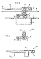
- 1 shows a section through a upper area of the pointer instrument according to the invention
- Figure 2 shows the pointer hub with light source
- Figure 3 the Section pointer flag and counterweight
- Figure 4 a section through the top of another Embodiment of the pointer instrument.
- Figure 1 shows a section through the upper region of a Pointer instrument.
- a stepper motor 10 is on the Back of an electrical circuit board on shaft 12, which protrudes through an opening in the printed circuit board 11, the hub 13 sits as part of the pointer.
- the hub 13 is via a flexible conductor 14 and two Contact pins 15 and 16 with the circuit board electrically contacted.
- the hub 13 continues to apply the end face of the pointer flag 18, for example is mechanically attached to the hub by means of locking means. From the viewer's point of view, behind the pointer flag is 18 a clock face 19 attached.
- the cover cap 20 here designed so that on the pointer flag opposite side of the cover cap Balance weight 21 is arranged.
- the outer end of the The light-guiding pointer flag 18 is metallic reflective film 22 covered in such a way that the shows the reflective side towards the pointer flag. This metallic reflective film 22 is for example hot stamped onto the end of the pointer flag.
- the light-emitting diode 17 is contacted via the Flex conductor 14 and the contact pins 15 and 16 with the PCB 11.
- Figure 2 shows the first lower assembly 26, which between Dial 19 and circuit board 11 is arranged and made the hub 13, the flexible conductor 14, the contact pins 15 and 16 and the illuminant 17.
- Figure 3 shows a second upper assembly 25, which on the side of the clock face facing the viewer 19 lies and from the pointer flag 18, the cap 20 and the balance weight 21 exists.
- FIG. 4 shows a second embodiment of the invention, the same reference numerals being used for the same components were and should not be explained again.
- the electrical contacting and the arrangement of Illuminants 17 and pointer flag 18 on the viewer facing end of the hub corresponds to the version in Figure 1.
- Only the arrangement of the balance weight 31st differs from the embodiment according to FIG. 1.
- the hub 33 was designed so that it Balance weight 31 of the pointer carries. So that can Balance weight advantageously on the viewer opposite side of the dial, which is shown in FIG not shown, may be arranged. This will make the Bearing load of the measuring mechanism is reduced and a significant higher vibration resistance achieved.
- it can Cover cap 30 can be made much smaller, which is again positive on the available area of the Dial affects.
- a substrate 32 which the different Compensates refractive indices.
- This substrate 32 can for example an immersion liquid, a silicone gel or an elastic intermediate piece such as silicone rubber or be a thermoplastic polyurethane elastomer.
Landscapes
- Engineering & Computer Science (AREA)
- Physics & Mathematics (AREA)
- General Physics & Mathematics (AREA)
- Chemical & Material Sciences (AREA)
- Combustion & Propulsion (AREA)
- Transportation (AREA)
- Mechanical Engineering (AREA)
- Details Of Measuring Devices (AREA)
Claims (9)
- Instrument indicateur comprenant un cadran (19), une aiguille indicatrice (18) fixée à un moyeu (13) monté tournant, un moyen d'éclairage (17) également fixé au moyeu et un capot de couverture (20, 30) qui peut être fixé sur le moyeu,
caractérisé en ce quele contact électrique du moyen d'éclairage (17) à un circuit imprimé (11) situé sur la face arrière du cadran (19) est assuré par un conducteur flexible (14),le moyeu (13), le moyen d'éclairage (17) et le conducteur flexible (14) constituent un premier groupe constructif (26) situé en bas et sur lequel peut être montée une aiguille indicatrice (18) faite d'un matériau conducteur de la lumière de manière à ce que la lumière fournie par le moyen d'éclairage (17) pénètre dans l'aiguille (18),l'aiguille (18) et le capot de couverture (20, 30) forment un second groupe constructif (25) situé en haut,le premier groupe (26), le second groupe (25) et le cadran (19) sont configurés de manière à ce que l'on peut monter successivement sur l'instrument indicateur, d'abord le premier groupe (26) puis le cadran gradué (19) et enfin le second groupe (25). - Instrument indicateur selon la revendication 1,
dans lequel
le moyen d'éclairage (17) est une diode luminescente, montée sur la face frontale du moyeu (13) tournée vers l'observateur. - Instrument selon la revendication 1 ou 2,
dans lequel
la face frontale du moyeu (13) portant, fixée sur elle, l'aiguille (18) et le moyen d'éclairage (17) est recouverte par le capot de couverture (20, 30) qui peut être fixé au moyeu (13). - Instrument selon l'une des revendications précédentes,
dans lequel
sur le côté du moyeu (13) opposé à l'aiguille, est monté un poids d'équilibrage (21, 31). - Instrument selon la revendication 4,
dans lequel
le poids d'équilibrage (21, 31) situé sur le moyeu (13) du côté du cadran faisant face à l'observateur est intégré au capot de couverture (20). - Instrument selon la revendication 4,
dans lequel
le poids d'équilibrage est monté sur le moyeu (13), du côté du cadran à chiffres (19) éloigné de l'observateur. - Instrument selon l'une des revendications précédentes,
dans lequel
l'extrémité indicatrice de l'aiguille est revêtue d'une feuille réfléchissante (22). - Instrument selon l'une des revendications précédentes,
dans lequel
le conducteur électrique flexible (14) est relié au circuit imprimé par des broches de contact (15, 16). - Instrument selon l'une des revendications précédentes,
dans lequel
un substrat est monté dans l'espace intermédiaire séparant la source de lumière et l'aiguille (18), pour compenser des indices de réfraction différents.
Applications Claiming Priority (2)
| Application Number | Priority Date | Filing Date | Title |
|---|---|---|---|
| DE19617553 | 1996-05-02 | ||
| DE19617553A DE19617553A1 (de) | 1996-05-02 | 1996-05-02 | Zeigerinstrument |
Publications (2)
| Publication Number | Publication Date |
|---|---|
| EP0805340A1 EP0805340A1 (fr) | 1997-11-05 |
| EP0805340B1 true EP0805340B1 (fr) | 2003-07-02 |
Family
ID=7793076
Family Applications (1)
| Application Number | Title | Priority Date | Filing Date |
|---|---|---|---|
| EP97106438A Expired - Lifetime EP0805340B1 (fr) | 1996-05-02 | 1997-04-18 | Aiguille de cadran indicateur |
Country Status (3)
| Country | Link |
|---|---|
| EP (1) | EP0805340B1 (fr) |
| JP (1) | JPH1038629A (fr) |
| DE (2) | DE19617553A1 (fr) |
Cited By (3)
| Publication number | Priority date | Publication date | Assignee | Title |
|---|---|---|---|---|
| DE102006053043A1 (de) * | 2006-11-10 | 2008-05-15 | Leopold Kostal Gmbh & Co. Kg | Bedieneinheit für ein Kraftfahrzeug |
| WO2017016733A1 (fr) | 2015-07-29 | 2017-02-02 | Robert Bosch Gmbh | Dispositif et procédé d'entrée et d'affichage de valeurs ainsi que système correspondant |
| DE102015214305A1 (de) | 2015-07-29 | 2017-02-02 | Robert Bosch Gmbh | Vorrichtung und Verfahren zum Ausgeben eines Steuersignals sowie entsprechendes System |
Families Citing this family (5)
| Publication number | Priority date | Publication date | Assignee | Title |
|---|---|---|---|---|
| DE19810854B4 (de) * | 1998-03-13 | 2007-12-20 | Siemens Ag | Zeigerinstrument |
| FR2857744B1 (fr) * | 2003-07-16 | 2005-10-28 | Johnson Contr Automotive Elect | Aiguille d'indicateur de bord a eclairage luminescent |
| DE102005049721A1 (de) | 2005-10-14 | 2007-04-26 | Borg Instruments Ag | Anzeigevorrichtung für ein Kraftfahrzeug mit einem einen ersten und/oder einen zweiten Lichtleiterbereich aufweisenden schwenkbaren Zeiger |
| JP5555516B2 (ja) * | 2010-03-23 | 2014-07-23 | 矢崎総業株式会社 | 指針装置 |
| EP2950168B1 (fr) * | 2014-05-27 | 2016-10-12 | The Swatch Group Research and Development Ltd. | Jeu d'aiguilles d'affichage lumineuses pour objet portable tel qu'une montre ou un instrument de mesure |
Citations (1)
| Publication number | Priority date | Publication date | Assignee | Title |
|---|---|---|---|---|
| EP0894244A1 (fr) * | 1996-04-19 | 1999-02-03 | Siemens Aktiengesellschaft | Instrument a aiguille |
Family Cites Families (10)
| Publication number | Priority date | Publication date | Assignee | Title |
|---|---|---|---|---|
| JPS5444545U (fr) * | 1977-09-02 | 1979-03-27 | ||
| JPS5441762A (en) * | 1977-09-09 | 1979-04-03 | Nissan Motor | Revolving pointer type meter |
| DE3837295A1 (de) * | 1988-11-03 | 1990-05-10 | Vdo Schindling | Zeigerinstrument |
| US5142453A (en) * | 1989-10-26 | 1992-08-25 | Yazaki Corporation | Illuminant pointer needle assembly for vehicular instrument |
| JP2507564Y2 (ja) * | 1990-03-30 | 1996-08-14 | 矢崎総業株式会社 | 車両用計器 |
| JPH0810780Y2 (ja) * | 1990-06-29 | 1996-03-29 | 矢崎総業株式会社 | 自動車用計器 |
| JP2526467B2 (ja) * | 1992-08-24 | 1996-08-21 | 日本電装株式会社 | 自発光指針式計器 |
| FR2708732B1 (fr) * | 1993-08-03 | 1995-10-20 | Jaeger | Ensemble indicateur et application aux tableaux de bord de véhicules automobiles. |
| JPH07286868A (ja) * | 1994-04-19 | 1995-10-31 | Nippondenso Co Ltd | 自発光指針式計器 |
| DE19527534B4 (de) * | 1994-07-28 | 2014-05-22 | Yazaki Corporation | Zeiger für Meßinstrumente, sein Herstellungsverfahren und seine Metallform |
-
1996
- 1996-05-02 DE DE19617553A patent/DE19617553A1/de not_active Withdrawn
-
1997
- 1997-04-18 DE DE59710362T patent/DE59710362D1/de not_active Expired - Lifetime
- 1997-04-18 EP EP97106438A patent/EP0805340B1/fr not_active Expired - Lifetime
- 1997-05-01 JP JP9113271A patent/JPH1038629A/ja active Pending
Patent Citations (1)
| Publication number | Priority date | Publication date | Assignee | Title |
|---|---|---|---|---|
| EP0894244A1 (fr) * | 1996-04-19 | 1999-02-03 | Siemens Aktiengesellschaft | Instrument a aiguille |
Cited By (5)
| Publication number | Priority date | Publication date | Assignee | Title |
|---|---|---|---|---|
| DE102006053043A1 (de) * | 2006-11-10 | 2008-05-15 | Leopold Kostal Gmbh & Co. Kg | Bedieneinheit für ein Kraftfahrzeug |
| WO2017016733A1 (fr) | 2015-07-29 | 2017-02-02 | Robert Bosch Gmbh | Dispositif et procédé d'entrée et d'affichage de valeurs ainsi que système correspondant |
| DE102015214319A1 (de) | 2015-07-29 | 2017-02-02 | Robert Bosch Gmbh | Vorrichtung und Verfahren zum Eingeben und Anzeigen von Werten sowie entsprechendes System |
| DE102015214305A1 (de) | 2015-07-29 | 2017-02-02 | Robert Bosch Gmbh | Vorrichtung und Verfahren zum Ausgeben eines Steuersignals sowie entsprechendes System |
| WO2017016734A1 (fr) | 2015-07-29 | 2017-02-02 | Robert Bosch Gmbh | Dispositif et procédé de production d'un signal de commande et système correspondant |
Also Published As
| Publication number | Publication date |
|---|---|
| DE59710362D1 (de) | 2003-08-07 |
| EP0805340A1 (fr) | 1997-11-05 |
| DE19617553A1 (de) | 1997-11-13 |
| JPH1038629A (ja) | 1998-02-13 |
Similar Documents
| Publication | Publication Date | Title |
|---|---|---|
| DE2839196A1 (de) | Anzeigeeinrichtung fuer ein messgeraet | |
| DE19632381A1 (de) | Kombinationsinstrument | |
| DE19540323B4 (de) | Drosselklappenstutzen | |
| DE29621803U1 (de) | Aufblasbarer Artikel mit einer Beleuchtungsvorrichtung | |
| DE2913138A1 (de) | Anzeigevorrichtung | |
| DE102014100640A1 (de) | Vorrichtigung zum Laden eines elektrisch betreibbaren Fahrzeugs | |
| DE19840070C2 (de) | Bedienelement für eine Fahrzeugkomponenten-Bedieneinheit | |
| DE112012000458T5 (de) | Anordnung zum Halten und Abdichten elektrischer Kabel und LED-Einheit | |
| DE19617553A1 (de) | Zeigerinstrument | |
| DE4110106A1 (de) | Messinstrument fuer kraftfahrzeuge | |
| EP0413776A1 (fr) | Commutateur fixe a la colonne de direction pour vehicules a moteur. | |
| DE4121607C2 (fr) | ||
| DE10237606A1 (de) | Kameraanordnung für Kraftfahrzeuge | |
| DE4427883C1 (de) | Einrichtung für Kraftfahrzeuge | |
| EP1633600B1 (fr) | Module verre a glace comportant des elements luminescents integres | |
| DE3837295C2 (fr) | ||
| EP0990873B1 (fr) | Aiguille de cadran indicateur | |
| WO1996019713A1 (fr) | Indicateur | |
| EP0943469B1 (fr) | Capteur de niveau de véhicule | |
| DE19543372B4 (de) | Winkelmeßeinrichtung | |
| EP0811827B1 (fr) | Dispositif de connexion pour tableau à aiguilles lumineuses | |
| EP0935740A1 (fr) | Instrument afficheur a plan d'affichage lumineux | |
| EP1679228B1 (fr) | Feu pour véhicule | |
| DE102022202354B3 (de) | Glasbaugruppe für eine Rückspiegelanordnung für Kraftfahrzeuge, sowie Verfahren zur Herstellung einer Glasbaugruppe | |
| DE102004044544A1 (de) | Vorrichtung zur Beleuchtung der Bedienungsblende einer Waschmaschine über das Elektronikgehäuse |
Legal Events
| Date | Code | Title | Description |
|---|---|---|---|
| PUAI | Public reference made under article 153(3) epc to a published international application that has entered the european phase |
Free format text: ORIGINAL CODE: 0009012 |
|
| AK | Designated contracting states |
Kind code of ref document: A1 Designated state(s): DE ES FR GB IT |
|
| 17P | Request for examination filed |
Effective date: 19980506 |
|
| 17Q | First examination report despatched |
Effective date: 20020115 |
|
| GRAH | Despatch of communication of intention to grant a patent |
Free format text: ORIGINAL CODE: EPIDOS IGRA |
|
| GRAH | Despatch of communication of intention to grant a patent |
Free format text: ORIGINAL CODE: EPIDOS IGRA |
|
| GRAA | (expected) grant |
Free format text: ORIGINAL CODE: 0009210 |
|
| AK | Designated contracting states |
Designated state(s): DE ES FR GB IT |
|
| PG25 | Lapsed in a contracting state [announced via postgrant information from national office to epo] |
Ref country code: IT Free format text: LAPSE BECAUSE OF FAILURE TO SUBMIT A TRANSLATION OF THE DESCRIPTION OR TO PAY THE FEE WITHIN THE PRE;WARNING: LAPSES OF ITALIAN PATENTS WITH EFFECTIVE DATE BEFORE 2007 MAY HAVE OCCURRED AT ANY TIME BEFORE 2007. THE CORRECT EFFECTIVE DATE MAY BE DIFFERENT FROM THE ONE RECORDED.SCRIBED TIME-LIMIT Effective date: 20030702 |
|
| REG | Reference to a national code |
Ref country code: GB Ref legal event code: FG4D Free format text: NOT ENGLISH |
|
| REF | Corresponds to: |
Ref document number: 59710362 Country of ref document: DE Date of ref document: 20030807 Kind code of ref document: P |
|
| PG25 | Lapsed in a contracting state [announced via postgrant information from national office to epo] |
Ref country code: ES Free format text: LAPSE BECAUSE OF FAILURE TO SUBMIT A TRANSLATION OF THE DESCRIPTION OR TO PAY THE FEE WITHIN THE PRESCRIBED TIME-LIMIT Effective date: 20031013 |
|
| GBT | Gb: translation of ep patent filed (gb section 77(6)(a)/1977) |
Effective date: 20031008 |
|
| ET | Fr: translation filed | ||
| PLBE | No opposition filed within time limit |
Free format text: ORIGINAL CODE: 0009261 |
|
| STAA | Information on the status of an ep patent application or granted ep patent |
Free format text: STATUS: NO OPPOSITION FILED WITHIN TIME LIMIT |
|
| 26N | No opposition filed |
Effective date: 20040405 |
|
| PGFP | Annual fee paid to national office [announced via postgrant information from national office to epo] |
Ref country code: GB Payment date: 20100324 Year of fee payment: 14 |
|
| PGFP | Annual fee paid to national office [announced via postgrant information from national office to epo] |
Ref country code: FR Payment date: 20100506 Year of fee payment: 14 |
|
| PGFP | Annual fee paid to national office [announced via postgrant information from national office to epo] |
Ref country code: DE Payment date: 20100624 Year of fee payment: 14 |
|
| REG | Reference to a national code |
Ref country code: DE Ref legal event code: R119 Ref document number: 59710362 Country of ref document: DE |
|
| REG | Reference to a national code |
Ref country code: DE Ref legal event code: R119 Ref document number: 59710362 Country of ref document: DE |
|
| GBPC | Gb: european patent ceased through non-payment of renewal fee |
Effective date: 20110418 |
|
| REG | Reference to a national code |
Ref country code: FR Ref legal event code: ST Effective date: 20111230 |
|
| PG25 | Lapsed in a contracting state [announced via postgrant information from national office to epo] |
Ref country code: FR Free format text: LAPSE BECAUSE OF NON-PAYMENT OF DUE FEES Effective date: 20110502 |
|
| PG25 | Lapsed in a contracting state [announced via postgrant information from national office to epo] |
Ref country code: GB Free format text: LAPSE BECAUSE OF NON-PAYMENT OF DUE FEES Effective date: 20110418 |
|
| PG25 | Lapsed in a contracting state [announced via postgrant information from national office to epo] |
Ref country code: DE Free format text: LAPSE BECAUSE OF NON-PAYMENT OF DUE FEES Effective date: 20111031 |