EP0805340B1 - Pointer instrument - Google Patents
Pointer instrument Download PDFInfo
- Publication number
- EP0805340B1 EP0805340B1 EP97106438A EP97106438A EP0805340B1 EP 0805340 B1 EP0805340 B1 EP 0805340B1 EP 97106438 A EP97106438 A EP 97106438A EP 97106438 A EP97106438 A EP 97106438A EP 0805340 B1 EP0805340 B1 EP 0805340B1
- Authority
- EP
- European Patent Office
- Prior art keywords
- pointer
- hub
- instrument according
- dial
- pointer instrument
- Prior art date
- Legal status (The legal status is an assumption and is not a legal conclusion. Google has not performed a legal analysis and makes no representation as to the accuracy of the status listed.)
- Expired - Lifetime
Links
Images

Classifications
-
- G—PHYSICS
- G12—INSTRUMENT DETAILS
- G12B—CONSTRUCTIONAL DETAILS OF INSTRUMENTS, OR COMPARABLE DETAILS OF OTHER APPARATUS, NOT OTHERWISE PROVIDED FOR
- G12B11/00—Indicating elements; Illumination thereof
- G12B11/04—Pointers; Setting-mechanisms therefor
-
- B—PERFORMING OPERATIONS; TRANSPORTING
- B60—VEHICLES IN GENERAL
- B60K—ARRANGEMENT OR MOUNTING OF PROPULSION UNITS OR OF TRANSMISSIONS IN VEHICLES; ARRANGEMENT OR MOUNTING OF PLURAL DIVERSE PRIME-MOVERS IN VEHICLES; AUXILIARY DRIVES FOR VEHICLES; INSTRUMENTATION OR DASHBOARDS FOR VEHICLES; ARRANGEMENTS IN CONNECTION WITH COOLING, AIR INTAKE, GAS EXHAUST OR FUEL SUPPLY OF PROPULSION UNITS IN VEHICLES
- B60K35/00—Instruments specially adapted for vehicles; Arrangement of instruments in or on vehicles
- B60K35/60—Instruments characterised by their location or relative disposition in or on vehicles
-
- G—PHYSICS
- G01—MEASURING; TESTING
- G01D—MEASURING NOT SPECIALLY ADAPTED FOR A SPECIFIC VARIABLE; ARRANGEMENTS FOR MEASURING TWO OR MORE VARIABLES NOT COVERED IN A SINGLE OTHER SUBCLASS; TARIFF METERING APPARATUS; MEASURING OR TESTING NOT OTHERWISE PROVIDED FOR
- G01D11/00—Component parts of measuring arrangements not specially adapted for a specific variable
- G01D11/28—Structurally-combined illuminating devices
-
- G—PHYSICS
- G01—MEASURING; TESTING
- G01D—MEASURING NOT SPECIALLY ADAPTED FOR A SPECIFIC VARIABLE; ARRANGEMENTS FOR MEASURING TWO OR MORE VARIABLES NOT COVERED IN A SINGLE OTHER SUBCLASS; TARIFF METERING APPARATUS; MEASURING OR TESTING NOT OTHERWISE PROVIDED FOR
- G01D13/00—Component parts of indicators for measuring arrangements not specially adapted for a specific variable
- G01D13/22—Pointers, e.g. settable pointer
-
- B—PERFORMING OPERATIONS; TRANSPORTING
- B60—VEHICLES IN GENERAL
- B60K—ARRANGEMENT OR MOUNTING OF PROPULSION UNITS OR OF TRANSMISSIONS IN VEHICLES; ARRANGEMENT OR MOUNTING OF PLURAL DIVERSE PRIME-MOVERS IN VEHICLES; AUXILIARY DRIVES FOR VEHICLES; INSTRUMENTATION OR DASHBOARDS FOR VEHICLES; ARRANGEMENTS IN CONNECTION WITH COOLING, AIR INTAKE, GAS EXHAUST OR FUEL SUPPLY OF PROPULSION UNITS IN VEHICLES
- B60K2360/00—Indexing scheme associated with groups B60K35/00 or B60K37/00 relating to details of instruments or dashboards
- B60K2360/20—Optical features of instruments
- B60K2360/33—Illumination features
Definitions
- the invention is based on a pointer instrument as is already known from the DE 38 37 295 C2 is known.
- the pointer instrument has one Pointer shaft arranged pointer, with a light source inside the pointer is attached, which serves the pointer lighting.
- the pointer thus represents this Pointer instrument is an active luminous pointer.
- a connection sleeve arranged between the measuring mechanism and the pointer in a rotationally fixed manner, the one assigned to the pointer Light source is contacted with the connecting sleeve via the pointer hub.
- the first embodiment is a connection between the electronics and a provide the first part of the pointer, the rotary transmitter, and continue to connect between the first part of the pointer serving as a rotary transmitter and the pointer flag to be provided with the actual light source.
- a display device for motor vehicles in which a a pointer needle arranged light is coupled.
- a needle holder on a circuit board on which a light-emitting Element is arranged that emits light into a pointer needle, which is held by the needle cap becomes.
- US 5,372,087 is an analog pointer element with a self-illuminating pointer known in which a pointer needle is supplied with a current via a flexible conductor element becomes. Numerous light sources are arranged on the pointer needle, their light in the direction a pointer cap and is thus directed towards a viewer.
- a display device for a vehicle dashboard is known, the pointer being off is made of a light-guiding material in which is arranged outside of the pointer Light source coupled in and in particular by one provided at the end of the pointer Reflector is directed towards a viewer.
- the pointer also has a Balance weight, which is arranged at the end opposite the pointer flag.
- Out JP 72 86 868 discloses a pointer device in which a pointer hub and a Pointer lugs are made in one piece and with electrical connections to the pointer hub Making contact to a flexible conductor are provided.
- the second connection between Rotary transformer and light source in the The pointer flag is eliminated because the pointer hub itself Carries light source and is used for contacting. So is a much easier assembly possible, which the Manufacturing costs can in turn be reduced. Furthermore is a by eliminating a second contact point much higher reliability of the pointer instrument given.
- Embodiments of the invention are in the drawing shown and in the description below explained.
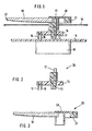
- 1 shows a section through a upper area of the pointer instrument according to the invention
- Figure 2 shows the pointer hub with light source
- Figure 3 the Section pointer flag and counterweight
- Figure 4 a section through the top of another Embodiment of the pointer instrument.
- Figure 1 shows a section through the upper region of a Pointer instrument.
- a stepper motor 10 is on the Back of an electrical circuit board on shaft 12, which protrudes through an opening in the printed circuit board 11, the hub 13 sits as part of the pointer.
- the hub 13 is via a flexible conductor 14 and two Contact pins 15 and 16 with the circuit board electrically contacted.
- the hub 13 continues to apply the end face of the pointer flag 18, for example is mechanically attached to the hub by means of locking means. From the viewer's point of view, behind the pointer flag is 18 a clock face 19 attached.
- the cover cap 20 here designed so that on the pointer flag opposite side of the cover cap Balance weight 21 is arranged.
- the outer end of the The light-guiding pointer flag 18 is metallic reflective film 22 covered in such a way that the shows the reflective side towards the pointer flag. This metallic reflective film 22 is for example hot stamped onto the end of the pointer flag.
- the light-emitting diode 17 is contacted via the Flex conductor 14 and the contact pins 15 and 16 with the PCB 11.
- Figure 2 shows the first lower assembly 26, which between Dial 19 and circuit board 11 is arranged and made the hub 13, the flexible conductor 14, the contact pins 15 and 16 and the illuminant 17.
- Figure 3 shows a second upper assembly 25, which on the side of the clock face facing the viewer 19 lies and from the pointer flag 18, the cap 20 and the balance weight 21 exists.
- FIG. 4 shows a second embodiment of the invention, the same reference numerals being used for the same components were and should not be explained again.
- the electrical contacting and the arrangement of Illuminants 17 and pointer flag 18 on the viewer facing end of the hub corresponds to the version in Figure 1.
- Only the arrangement of the balance weight 31st differs from the embodiment according to FIG. 1.
- the hub 33 was designed so that it Balance weight 31 of the pointer carries. So that can Balance weight advantageously on the viewer opposite side of the dial, which is shown in FIG not shown, may be arranged. This will make the Bearing load of the measuring mechanism is reduced and a significant higher vibration resistance achieved.
- it can Cover cap 30 can be made much smaller, which is again positive on the available area of the Dial affects.
- a substrate 32 which the different Compensates refractive indices.
- This substrate 32 can for example an immersion liquid, a silicone gel or an elastic intermediate piece such as silicone rubber or be a thermoplastic polyurethane elastomer.
Landscapes
- Engineering & Computer Science (AREA)
- Physics & Mathematics (AREA)
- General Physics & Mathematics (AREA)
- Chemical & Material Sciences (AREA)
- Combustion & Propulsion (AREA)
- Transportation (AREA)
- Mechanical Engineering (AREA)
- Details Of Measuring Devices (AREA)
Description
Die Erfindung geht aus von einem Zeigerinstrumentwie es aus bereits aus der DE 38 37 295 C2 bekannt ist. Hierbei weist das Zeigerinstrument einen auf einer Zeigerwelle angeordneten Zeiger auf, wobei im Zeigerinneren eine Lichtquelle angebracht ist, die der Zeigerbeleuchtung dient. Damit stellt der Zeiger dieses Zeigerinstrumentes einen aktiven Leuchtzeiger dar. Hierbei ist eine Anschlußhülse zwischen Meßwerk und Zeiger drehfest angeordnet, wobei die dem Zeiger zugeordnete Lichtquelle mit der Anschlußhülse über die Zeigernabe kontaktiert ist. Bei dieser Ausführungsform ist also zunächst eine Verbindung zwischen der Elektronik und einem ersten Teil des Zeigers, dem Drehübertrager, vorzusehen und weiterhin eine Verbindung zwischen dem als Drehübertrager dienenden ersten Teil des Zeigers und der Zeigerfahne mit der eigentlichen Lichtquelle vorzusehen.The invention is based on a pointer instrument as is already known from the DE 38 37 295 C2 is known. Here, the pointer instrument has one Pointer shaft arranged pointer, with a light source inside the pointer is attached, which serves the pointer lighting. The pointer thus represents this Pointer instrument is an active luminous pointer. Here is a connection sleeve arranged between the measuring mechanism and the pointer in a rotationally fixed manner, the one assigned to the pointer Light source is contacted with the connecting sleeve via the pointer hub. At this The first embodiment is a connection between the electronics and a provide the first part of the pointer, the rotary transmitter, and continue to connect between the first part of the pointer serving as a rotary transmitter and the pointer flag to be provided with the actual light source.
Aus der DE 41 21 607 A1 ist ein Anzeigegerät für Kraftfahrzeuge bekannt, bei der in eine über einer Skalenscheibe angeordnete Zeigernadel Licht eingekoppelt wird. In einem Ausführungsbeispiel verfügt ein Nadelhalter über eine Platine, an der ein lichtabgebendes Element angeordnet ist, das Licht in eine Zeigernadel abgibt, die von der Nadelkappe gehalten wird. Aus der US 5,372,087 ist ein analoges Zeigerelement mit einem selbstleuchtenden Zeiger bekannt, bei der eine Zeigernadel über ein flexibles Leiterelement mit einem Strom versorgt wird. Auf der Zeigernadel sind zahlreiche Lichtquellen angeordnet, deren Licht in Richtung einer Zeigerkappe und damit in Richtung eines Betrachters gelenkt wird. Aus der FR 2 708 732 A1 ist eine Anzeigevorrichtung für ein Fahrzeugarmaturenbrett bekannt, wobei der Zeiger aus einem lichtleitenden Material gefertigt ist, in das von einer außerhalb dem Zeiger angeordneten Lichtquelle Licht eingekoppelt und insbesondere durch einen an dem Zeigerende vorgesehenen Reflektor in Richtung eines Betrachters gelenkt wird. Ferner verfügt der Zeiger über ein Ausgleichsgewicht, das an dem der Zeigerfahne gegenüberliegenden Ende angeordnet ist. Aus der JP 72 86 868 (Abstract) ist eine Zeigervorrichtung bekannt, bei der eine Zeigernabe und eine Zeigerfahne einstückig ausgeführt sind und wobei an der Zeigernabe elektrische Anschlüsse zur Herstellung eines Kontaktes zu einem flexiblen Leiter vorgesehen sind. From DE 41 21 607 A1 a display device for motor vehicles is known, in which a a pointer needle arranged light is coupled. In one Exemplary embodiment has a needle holder on a circuit board on which a light-emitting Element is arranged that emits light into a pointer needle, which is held by the needle cap becomes. From US 5,372,087 is an analog pointer element with a self-illuminating pointer known in which a pointer needle is supplied with a current via a flexible conductor element becomes. Numerous light sources are arranged on the pointer needle, their light in the direction a pointer cap and is thus directed towards a viewer. From FR 2 708 732 A1, a display device for a vehicle dashboard is known, the pointer being off is made of a light-guiding material in which is arranged outside of the pointer Light source coupled in and in particular by one provided at the end of the pointer Reflector is directed towards a viewer. The pointer also has a Balance weight, which is arranged at the end opposite the pointer flag. Out JP 72 86 868 (abstract) discloses a pointer device in which a pointer hub and a Pointer lugs are made in one piece and with electrical connections to the pointer hub Making contact to a flexible conductor are provided.
Aus der nachveröffentlichten Druckschrift WO 97/40346, bei der die Vertragsstaaten Deutschland, Frankreich und Großbritannien benannt sind, ist ein Zeigerinstrument beschrieben, bei der in einem Ausführungsbeispiel ein LED-Chip auf einer Anschlusshülse befestigt ist, die auf der Zeigerwelle befestigt ist und den Zeiger hält. Die Anschlusshülse ist aus einem leitfähigen Kunststoffmaterial hergestellt und über einen flexiblen Leiter mit einer Leiterplatte kontaktiert.From the subsequently published publication WO 97/40346, in which the contracting states Germany, France and Britain are named is a pointer instrument described in which, in one embodiment, an LED chip on a Connection sleeve is attached, which is attached to the pointer shaft and holds the pointer. The Connection sleeve is made of a conductive plastic material and over a flexible conductor contacted with a circuit board.
Bei dem erfindungsgemäßen Zeigerinstrument kann die zweite Verbindung zwischen Drehübertrager und Lichtquelle in der Zeigerfahne entfallen, da die Zeigernabe selbst die Lichtquelle trägt und zur Kontaktierung dient. Somit ist eine wesentlich einfachere Montage möglich, wodurch die Fertigungskosten wiederum herabgesetzt werden. Des weiteren ist durch den Wegfall einer zweiten Kontaktstelle eine wesentlich höhere Zuverlässigkeit des Zeigerinstrumentes gegeben.In the pointer instrument according to the invention, the second connection between Rotary transformer and light source in the The pointer flag is eliminated because the pointer hub itself Carries light source and is used for contacting. So is a much easier assembly possible, which the Manufacturing costs can in turn be reduced. Furthermore is a by eliminating a second contact point much higher reliability of the pointer instrument given.
Durch die Unteransprüche sind vorteilhafte Ausgestaltungen und Weiterbildungen des erfindungsgemäßen Zeigerinstrumentes gegeben. So kann beispielsweise durch das Anbringen des Ausgleichsgewichtes für den Zeiger an der Nabe nahe der Lagerstelle des Meßwerks die Belastung des Meßwerkes reduziert werden und das Zeiger-Design wesentlich freier gestaltet werden. Durch das Einbringen eines transparenten, elastischen Zwischenstückes wird wiederum die Lichteinkopplung in die Zeigerfahne verbessert. Letztendlich wird die Lichtausbeute dadurch erhöht, daß ein reflektierender Körper am äußeren Ende der Zeigerfahne aufgebracht wird.Advantageous refinements are given by the subclaims and further developments of the pointer instrument according to the invention given. For example, by attaching the Balance weight for the pointer on the hub near the Bearing of the measuring mechanism the load of the measuring mechanism be reduced and the pointer design much freer be designed. By introducing a transparent, elastic intermediate piece will in turn Light coupling in the pointer flag improved. At long last the luminous efficacy is increased in that a reflective body at the outer end of the pointer flag is applied.
Ausführungsbeispiele der Erfindung sind in der Zeichnung dargestellt und in der nachfolgenden Beschreibung näher erläutert. Es zeigen Figur 1 einen Schnitt durch einen oberen Bereich des erfindungsgemäßen Zeigerinstrumentes, Figur 2 die Zeigernabe mit Lichtquelle, Figur 3 den Abschnitt Zeigerfahne und Ausgleichsgewicht und Figur 4 einen Schnitt durch den oberen Bereich eines weiteren Ausführungsbeispieles des Zeigerinstrumentes. Embodiments of the invention are in the drawing shown and in the description below explained. 1 shows a section through a upper area of the pointer instrument according to the invention, Figure 2 shows the pointer hub with light source, Figure 3 the Section pointer flag and counterweight and Figure 4 a section through the top of another Embodiment of the pointer instrument.
Figur 1 zeigt einen Schnitt durch den oberen Bereich eines
Zeigerinstrumentes. Ein Schrittmotor 10 ist auf der
Rückseite einer elektrischen Leiterplatte auf der Welle 12,
die durch eine Öffnung der Leiterplatte 11 hindurchragt,
sitzt die Nabe 13 als ein zum Zeiger gehörendes Teil.
Die Nabe 13 ist über einen Flexleiter 14 und zwei
Kontaktstifte 15 und 16 mit der Leiterplatte elektrisch
kontaktiert. Auf der dem Betrachter zugewandten Stirnfläche
der Nabe 13, die im wesentlichen einen zylindrischen
Querschnitt hat, ist ein Leuchtmittel 17 in Form einer
Leuchtdiode angebracht. Die Nabe 13 trägt weiterhin auf
ihrer Stirnfläche die Zeigerfahne 18, die beispielsweise
mittels Rastmittel auf der Nabe mechanisch befestigt ist.
Aus der Sicht des Betrachters ist hinter der Zeigerfahne 18
ein Ziffernblatt 19 befestigt. Auf der dem Betrachter
abgewandten Seite des Ziffernblattes 19 liegen die
Leiterplatte mit Schrittmotor und den Flexleiter 14, sie
sind damit für den Betrachter nicht zu sehen. Die Stirnseite
der Nabe 13, welche das Leuchtmittel 17 trägt und an welcher
die Zeigerfahne 18 verrastet ist, wird durch eine
Abdeckkappe 20 in der Art umschlossen, daß die lichtleitende
Zeigerfahne 18 in der hauptsächlichen Abstrahlrichtung des
Leuchtmittels so fixiert ist, daß ein sehr großer Teil des
Lichtes aus dem Leuchtmittel in die lichtleitende
Zeigerfahne 18 eingekoppelt wird. In dem ersten
Ausführungsbeispiel der Figur 1 ist die Abdeckkappe 20
hierbei so gestaltet, daß auf der der Zeigerfahne
gegenüberliegenden Seite der Abdeckkappe ein
Ausgleichsgewicht 21 angeordnet ist. Das äußere Ende der
lichtleitenden Zeigerfahne 18 ist mit einer metallisch
reflektierenden Folie 22 in der Art abgedeckt, daß die
reflektierende Seite zur Zeigerfahne hin zeigt. Diese
metallisch reflektierende Folie 22 ist beispielsweise
mittels Heißprägen auf das Ende der Zeigerfahne aufgebracht.
Die Kontaktierung der Leuchtdiode 17 erfolgt dabei über den
Flexleiter 14 und die Kontaktstifte 15 und 16 mit der
Leiterplatte 11.Figure 1 shows a section through the upper region of a
Pointer instrument. A
Diese Ausführungsform des oberen Bereichs eines Zeigerinstrumentes erlaubt eine sehr einfache und kostengünstige Montage des Zeigerinstrumentes. So sind in den Figuren 2 und 3 die zu montierenden Baugruppen dargestellt, die dann durch einfaches Verrasten miteinander montiert werden.This embodiment of the top of a Pointer instrument allows a very simple and inexpensive assembly of the pointer instrument. So are in Figures 2 and 3, the assemblies to be assembled shown, which are then simply locked together to be assembled.
Figur 2 zeigt die erste untere Baugruppe 26, welche zwischen
Ziffernblatt 19 und Leiterplatte 11 angeordnet ist und aus
der Nabe 13, dem Flexleiter 14, den Kontaktstiften 15 und 16
und dem Leuchtmittel 17 besteht.Figure 2 shows the first
Figur 3 zeigt hierbei eine zweite obere Baugruppe 25, welche
auf der dem Betrachter zugewandten Seite des Ziffernblattes
19 liegt und aus der Zeigerfahne 18, der Abdeckkappe 20 und
dem Ausgleichsgewicht 21 besteht.Figure 3 shows a second
Diese beiden Baugruppen 25 und 26 können fertig vormontiert
werden und anschließend sehr einfach auf der Leiterplatte 11
mit dem rückwärtig angeordneten Schrittmotor 10 aufgebracht
werden. Hierfür wird zunächst die erste untere Baugruppe 26
auf die Zeigerwelle 12 und damit auf das Meßwerk montiert.
Anschließend wird das Ziffernblatt 19 aufgesetzt und dann
die zweite obere Bauteilegruppe 25 mit seiner Abdeckkappe 20
über die Nabe 13 geschoben. These two
Figur 4 zeigt eine zweite Ausführungsform der Erfindung,
wobei gleiche Bezugszeichen für gleiche Bauteile verwendet
wurden und nicht nochmals näher erläutert werden sollen. Die
elektrische Kontaktierung und die Anordnung von
Leuchtmitteln 17 und Zeigerfahne 18 auf der dem Betrachter
zugewandten Stirnseite der Nabe entspricht der Ausführung in
Figur 1. Lediglich die Anordnung des Ausgleichsgewichtes 31
unterscheidet sich von der Ausführungsform gemäß Figur 1. In
dieser Figur 4 wurde die Nabe 33 so gestaltet, daß sie das
Ausgleichsgewicht 31 des Zeigers trägt. Damit kann das
Ausgleichsgewicht vorteilhafterweise auf der dem Betrachter
abgewandten Seite des Ziffernblattes, welches in Figur 4
nicht dargestellt ist, angeordnet sein. Hierdurch wird die
Lagerbelastung des Meßwerkes reduziert und eine wesentlich
höhere Vibrationsfestigkeit ereicht. Letztendlich kann die
Abdeckkappe 30 wesentlich kleiner gestaltet werden, was sich
wiederum positiv auf die zur Verfügung stehende Fläche des
Ziffernblattes auswirkt.FIG. 4 shows a second embodiment of the invention,
the same reference numerals being used for the same components
were and should not be explained again. The
electrical contacting and the arrangement of
Illuminants 17 and
Für eine möglichst verlustarme Lichtübertragung von der
Leuchtdiode 17 zur Zeigerfahne 18 wird in den Zwischenraum
ein Substrat 32 eingebracht, welches die unterschiedlichen
Brechungszahlen ausgleicht. Dieses Substrat 32 kann
beispielsweise eine Immersionsflüssigkeit, ein Silikongel
oder ein elastisches Zwischenstück wie Silikonkautschuk oder
ein thermoplastisches Polyurethan-Elastomer sein.For the lowest possible loss of light from the
Claims (9)
- Pointer instrument with a dial (19), with a pointer vane (18) fastened on a rotatably mounted hub (13), with a lighting means (17), likewise fastened on the hub (13) and a covering cap (20, 30), which can be fastened on the hub, the electrical contacting of the lighting means (17) with respect to a printed circuit board (11) located on the rear side of the dial taking place via a flexible electrical conductor (14), and the hub (13), the lighting means (17) and the flexible electrical conductor (14) forming a first, lower subassembly (26), onto which a pointer vane (18) consisting of a light-conducting material can be mounted in such a way that the light supplied by the lighting means (17) shines into the pointer vane (18), the pointer vane (18) and the covering cap (20, 30) forming a second, upper subassembly (25), the first, lower subassembly (26), the second, upper subassembly (25) and the dial (19) being configured in such a way that the first subassembly (26) can be mounted on the pointer instrument first, then the dial (19) and subsequently the second subassembly (25).
- Pointer instrument according to Claim 1, the lighting means (17) being a light-emitting diode and being mounted on the end face of the hub (13) facing the viewer.
- Pointer instrument according to either of Claims 1 and 2, the end face of the hub (13) with the fastened pointer vane (18) and the lighting means (17) mounted on it being covered by the covering cap (20, 30), which can be fastened on the hub (13).
- Pointer instrument according to one of the preceding claims, a balancing weight (21, 31) being attached on the side of the hub (13) opposite from the pointer vane.
- Pointer instrument according to Claim 4, the balancing weight (21, 31) at the hub (13) being integrated into the covering cap (20) on the side of the dial facing the viewer.
- Pointer instrument according to Claim 4, the balancing weight at the hub (13) being arranged on the side of the dial (19) facing away from the viewer.
- Pointer instrument according to one of the preceding claims, the pointer end of the pointer vane being coated with a reflective film (22).
- Pointer instrument according to one of the preceding claims, the flexible electrical conductor (14) being contacted with respect to the printed circuit board via electrical contact pins (15, 16).
- Pointer instrument according to one of the preceding claims, a substrate to compensate for different refractive indices being arranged in an intermediate space between the light source and the pointer vane (18).
Applications Claiming Priority (2)
| Application Number | Priority Date | Filing Date | Title |
|---|---|---|---|
| DE19617553 | 1996-05-02 | ||
| DE19617553A DE19617553A1 (en) | 1996-05-02 | 1996-05-02 | Pointer instrument |
Publications (2)
| Publication Number | Publication Date |
|---|---|
| EP0805340A1 EP0805340A1 (en) | 1997-11-05 |
| EP0805340B1 true EP0805340B1 (en) | 2003-07-02 |
Family
ID=7793076
Family Applications (1)
| Application Number | Title | Priority Date | Filing Date |
|---|---|---|---|
| EP97106438A Expired - Lifetime EP0805340B1 (en) | 1996-05-02 | 1997-04-18 | Pointer instrument |
Country Status (3)
| Country | Link |
|---|---|
| EP (1) | EP0805340B1 (en) |
| JP (1) | JPH1038629A (en) |
| DE (2) | DE19617553A1 (en) |
Cited By (3)
| Publication number | Priority date | Publication date | Assignee | Title |
|---|---|---|---|---|
| DE102006053043A1 (en) * | 2006-11-10 | 2008-05-15 | Leopold Kostal Gmbh & Co. Kg | Operating unit for a motor vehicle |
| WO2017016733A1 (en) | 2015-07-29 | 2017-02-02 | Robert Bosch Gmbh | Apparatus and method for inputting and displaying values, and corresponding system |
| DE102015214305A1 (en) | 2015-07-29 | 2017-02-02 | Robert Bosch Gmbh | Device and method for outputting a control signal and corresponding system |
Families Citing this family (5)
| Publication number | Priority date | Publication date | Assignee | Title |
|---|---|---|---|---|
| DE19810854B4 (en) * | 1998-03-13 | 2007-12-20 | Siemens Ag | pointer instrument |
| FR2857744B1 (en) * | 2003-07-16 | 2005-10-28 | Johnson Contr Automotive Elect | LUMINESCENT LIGHT INDICATOR NEEDLE |
| DE102005049721A1 (en) | 2005-10-14 | 2007-04-26 | Borg Instruments Ag | Display device for a motor vehicle with a first and / or a second light guide region having pivotable pointer |
| JP5555516B2 (en) * | 2010-03-23 | 2014-07-23 | 矢崎総業株式会社 | Pointer device |
| EP2950168B1 (en) * | 2014-05-27 | 2016-10-12 | The Swatch Group Research and Development Ltd. | Set of luminous display hands for a portable object such as a watch or a measuring instrument |
Citations (1)
| Publication number | Priority date | Publication date | Assignee | Title |
|---|---|---|---|---|
| EP0894244A1 (en) * | 1996-04-19 | 1999-02-03 | Siemens Aktiengesellschaft | Pointer instrument |
Family Cites Families (10)
| Publication number | Priority date | Publication date | Assignee | Title |
|---|---|---|---|---|
| JPS5444545U (en) * | 1977-09-02 | 1979-03-27 | ||
| JPS5441762A (en) * | 1977-09-09 | 1979-04-03 | Nissan Motor | Revolving pointer type meter |
| DE3837295A1 (en) * | 1988-11-03 | 1990-05-10 | Vdo Schindling | POINTER INSTRUMENT |
| US5142453A (en) * | 1989-10-26 | 1992-08-25 | Yazaki Corporation | Illuminant pointer needle assembly for vehicular instrument |
| JP2507564Y2 (en) * | 1990-03-30 | 1996-08-14 | 矢崎総業株式会社 | Vehicle instrument |
| JPH0810780Y2 (en) * | 1990-06-29 | 1996-03-29 | 矢崎総業株式会社 | Automotive instrument |
| JP2526467B2 (en) * | 1992-08-24 | 1996-08-21 | 日本電装株式会社 | Self-luminous pointer type instrument |
| FR2708732B1 (en) * | 1993-08-03 | 1995-10-20 | Jaeger | Indicator and application set for dashboards of motor vehicles. |
| JPH07286868A (en) * | 1994-04-19 | 1995-10-31 | Nippondenso Co Ltd | Self-luminous pointer type instrument |
| DE19527534B4 (en) * | 1994-07-28 | 2014-05-22 | Yazaki Corporation | Pointer for measuring instruments, its manufacturing process and its metal form |
-
1996
- 1996-05-02 DE DE19617553A patent/DE19617553A1/en not_active Withdrawn
-
1997
- 1997-04-18 DE DE59710362T patent/DE59710362D1/en not_active Expired - Lifetime
- 1997-04-18 EP EP97106438A patent/EP0805340B1/en not_active Expired - Lifetime
- 1997-05-01 JP JP9113271A patent/JPH1038629A/en active Pending
Patent Citations (1)
| Publication number | Priority date | Publication date | Assignee | Title |
|---|---|---|---|---|
| EP0894244A1 (en) * | 1996-04-19 | 1999-02-03 | Siemens Aktiengesellschaft | Pointer instrument |
Cited By (5)
| Publication number | Priority date | Publication date | Assignee | Title |
|---|---|---|---|---|
| DE102006053043A1 (en) * | 2006-11-10 | 2008-05-15 | Leopold Kostal Gmbh & Co. Kg | Operating unit for a motor vehicle |
| WO2017016733A1 (en) | 2015-07-29 | 2017-02-02 | Robert Bosch Gmbh | Apparatus and method for inputting and displaying values, and corresponding system |
| DE102015214319A1 (en) | 2015-07-29 | 2017-02-02 | Robert Bosch Gmbh | Device and method for entering and displaying values and corresponding system |
| DE102015214305A1 (en) | 2015-07-29 | 2017-02-02 | Robert Bosch Gmbh | Device and method for outputting a control signal and corresponding system |
| WO2017016734A1 (en) | 2015-07-29 | 2017-02-02 | Robert Bosch Gmbh | Apparatus and method for outputting a control signal, and corresponding system |
Also Published As
| Publication number | Publication date |
|---|---|
| DE59710362D1 (en) | 2003-08-07 |
| EP0805340A1 (en) | 1997-11-05 |
| DE19617553A1 (en) | 1997-11-13 |
| JPH1038629A (en) | 1998-02-13 |
Similar Documents
| Publication | Publication Date | Title |
|---|---|---|
| DE2839196A1 (en) | DISPLAY DEVICE FOR A MEASURING DEVICE | |
| DE19632381A1 (en) | Combination instrument | |
| DE19540323B4 (en) | throttle body | |
| DE29621803U1 (en) | Inflatable article with a lighting device | |
| DE2913138A1 (en) | DISPLAY DEVICE | |
| DE102014100640A1 (en) | Device for charging an electrically operable vehicle | |
| DE19840070C2 (en) | Control element for a vehicle component control unit | |
| DE112012000458T5 (en) | Arrangement for holding and sealing electrical cables and LED unit | |
| DE19617553A1 (en) | Pointer instrument | |
| DE4110106A1 (en) | MEASURING INSTRUMENT FOR MOTOR VEHICLES | |
| EP0413776A1 (en) | Steering column switch for motor vehicles. | |
| DE4121607C2 (en) | ||
| DE10237606A1 (en) | Windscreen camera-mounting arrangement for use in vehicles includes further circuit board for analysis electronics in horizontal arrangement | |
| DE4427883C1 (en) | Road vehicle steering column mounted electrical and optical switching unit | |
| EP1633600B1 (en) | Mirror glass component with integrated illuminating means | |
| DE3837295C2 (en) | ||
| EP0990873B1 (en) | Pointer instrument | |
| WO1996019713A1 (en) | Indicator | |
| EP0943469B1 (en) | Vehicle level sensor | |
| DE19543372B4 (en) | angle measuring device | |
| EP0811827B1 (en) | Connecting device for dashboard with self-luminescent pointers | |
| EP0935740A1 (en) | Display panel with a luminous display field | |
| EP1679228B1 (en) | Vehicle lamp | |
| DE102022202354B3 (en) | Glass assembly for a rearview mirror assembly for motor vehicles, and method for manufacturing a glass assembly | |
| DE102004044544A1 (en) | Device for illuminating the control panel of a washing machine via the electronics housing |
Legal Events
| Date | Code | Title | Description |
|---|---|---|---|
| PUAI | Public reference made under article 153(3) epc to a published international application that has entered the european phase |
Free format text: ORIGINAL CODE: 0009012 |
|
| AK | Designated contracting states |
Kind code of ref document: A1 Designated state(s): DE ES FR GB IT |
|
| 17P | Request for examination filed |
Effective date: 19980506 |
|
| 17Q | First examination report despatched |
Effective date: 20020115 |
|
| GRAH | Despatch of communication of intention to grant a patent |
Free format text: ORIGINAL CODE: EPIDOS IGRA |
|
| GRAH | Despatch of communication of intention to grant a patent |
Free format text: ORIGINAL CODE: EPIDOS IGRA |
|
| GRAA | (expected) grant |
Free format text: ORIGINAL CODE: 0009210 |
|
| AK | Designated contracting states |
Designated state(s): DE ES FR GB IT |
|
| PG25 | Lapsed in a contracting state [announced via postgrant information from national office to epo] |
Ref country code: IT Free format text: LAPSE BECAUSE OF FAILURE TO SUBMIT A TRANSLATION OF THE DESCRIPTION OR TO PAY THE FEE WITHIN THE PRE;WARNING: LAPSES OF ITALIAN PATENTS WITH EFFECTIVE DATE BEFORE 2007 MAY HAVE OCCURRED AT ANY TIME BEFORE 2007. THE CORRECT EFFECTIVE DATE MAY BE DIFFERENT FROM THE ONE RECORDED.SCRIBED TIME-LIMIT Effective date: 20030702 |
|
| REG | Reference to a national code |
Ref country code: GB Ref legal event code: FG4D Free format text: NOT ENGLISH |
|
| REF | Corresponds to: |
Ref document number: 59710362 Country of ref document: DE Date of ref document: 20030807 Kind code of ref document: P |
|
| PG25 | Lapsed in a contracting state [announced via postgrant information from national office to epo] |
Ref country code: ES Free format text: LAPSE BECAUSE OF FAILURE TO SUBMIT A TRANSLATION OF THE DESCRIPTION OR TO PAY THE FEE WITHIN THE PRESCRIBED TIME-LIMIT Effective date: 20031013 |
|
| GBT | Gb: translation of ep patent filed (gb section 77(6)(a)/1977) |
Effective date: 20031008 |
|
| ET | Fr: translation filed | ||
| PLBE | No opposition filed within time limit |
Free format text: ORIGINAL CODE: 0009261 |
|
| STAA | Information on the status of an ep patent application or granted ep patent |
Free format text: STATUS: NO OPPOSITION FILED WITHIN TIME LIMIT |
|
| 26N | No opposition filed |
Effective date: 20040405 |
|
| PGFP | Annual fee paid to national office [announced via postgrant information from national office to epo] |
Ref country code: GB Payment date: 20100324 Year of fee payment: 14 |
|
| PGFP | Annual fee paid to national office [announced via postgrant information from national office to epo] |
Ref country code: FR Payment date: 20100506 Year of fee payment: 14 |
|
| PGFP | Annual fee paid to national office [announced via postgrant information from national office to epo] |
Ref country code: DE Payment date: 20100624 Year of fee payment: 14 |
|
| REG | Reference to a national code |
Ref country code: DE Ref legal event code: R119 Ref document number: 59710362 Country of ref document: DE |
|
| REG | Reference to a national code |
Ref country code: DE Ref legal event code: R119 Ref document number: 59710362 Country of ref document: DE |
|
| GBPC | Gb: european patent ceased through non-payment of renewal fee |
Effective date: 20110418 |
|
| REG | Reference to a national code |
Ref country code: FR Ref legal event code: ST Effective date: 20111230 |
|
| PG25 | Lapsed in a contracting state [announced via postgrant information from national office to epo] |
Ref country code: FR Free format text: LAPSE BECAUSE OF NON-PAYMENT OF DUE FEES Effective date: 20110502 |
|
| PG25 | Lapsed in a contracting state [announced via postgrant information from national office to epo] |
Ref country code: GB Free format text: LAPSE BECAUSE OF NON-PAYMENT OF DUE FEES Effective date: 20110418 |
|
| PG25 | Lapsed in a contracting state [announced via postgrant information from national office to epo] |
Ref country code: DE Free format text: LAPSE BECAUSE OF NON-PAYMENT OF DUE FEES Effective date: 20111031 |