EP0805029B1 - Substrat für ein Element eines Tintenstrahldruckkopfes, Tintenstrahldruckkopf und Tintenstrahldruckapparat - Google Patents
Substrat für ein Element eines Tintenstrahldruckkopfes, Tintenstrahldruckkopf und Tintenstrahldruckapparat Download PDFInfo
- Publication number
- EP0805029B1 EP0805029B1 EP97302612A EP97302612A EP0805029B1 EP 0805029 B1 EP0805029 B1 EP 0805029B1 EP 97302612 A EP97302612 A EP 97302612A EP 97302612 A EP97302612 A EP 97302612A EP 0805029 B1 EP0805029 B1 EP 0805029B1
- Authority
- EP
- European Patent Office
- Prior art keywords
- ink
- heating elements
- set forth
- driving
- print head
- Prior art date
- Legal status (The legal status is an assumption and is not a legal conclusion. Google has not performed a legal analysis and makes no representation as to the accuracy of the status listed.)
- Expired - Lifetime
Links
- 239000000758 substrate Substances 0.000 title claims description 54
- 238000007641 inkjet printing Methods 0.000 title claims description 51
- 238000010438 heat treatment Methods 0.000 claims description 102
- 238000007639 printing Methods 0.000 claims description 58
- 230000020169 heat generation Effects 0.000 claims description 7
- 239000000976 ink Substances 0.000 description 90
- 239000010410 layer Substances 0.000 description 30
- 239000007788 liquid Substances 0.000 description 11
- 238000010276 construction Methods 0.000 description 10
- VYPSYNLAJGMNEJ-UHFFFAOYSA-N Silicium dioxide Chemical compound O=[Si]=O VYPSYNLAJGMNEJ-UHFFFAOYSA-N 0.000 description 6
- 238000009413 insulation Methods 0.000 description 5
- 230000005587 bubbling Effects 0.000 description 4
- 238000011084 recovery Methods 0.000 description 4
- 229910052581 Si3N4 Inorganic materials 0.000 description 3
- XUIMIQQOPSSXEZ-UHFFFAOYSA-N Silicon Chemical compound [Si] XUIMIQQOPSSXEZ-UHFFFAOYSA-N 0.000 description 3
- 238000009825 accumulation Methods 0.000 description 3
- 230000005540 biological transmission Effects 0.000 description 3
- 238000009835 boiling Methods 0.000 description 3
- 230000015556 catabolic process Effects 0.000 description 3
- 238000004140 cleaning Methods 0.000 description 3
- 229910052681 coesite Inorganic materials 0.000 description 3
- 229910052906 cristobalite Inorganic materials 0.000 description 3
- 238000010586 diagram Methods 0.000 description 3
- 230000000694 effects Effects 0.000 description 3
- 239000012535 impurity Substances 0.000 description 3
- 239000011229 interlayer Substances 0.000 description 3
- 238000004519 manufacturing process Methods 0.000 description 3
- 239000011241 protective layer Substances 0.000 description 3
- 230000002441 reversible effect Effects 0.000 description 3
- 229910052710 silicon Inorganic materials 0.000 description 3
- 239000010703 silicon Substances 0.000 description 3
- 239000000377 silicon dioxide Substances 0.000 description 3
- 239000007787 solid Substances 0.000 description 3
- 229910052682 stishovite Inorganic materials 0.000 description 3
- 229910052905 tridymite Inorganic materials 0.000 description 3
- 230000015572 biosynthetic process Effects 0.000 description 2
- 238000005229 chemical vapour deposition Methods 0.000 description 2
- 238000009792 diffusion process Methods 0.000 description 2
- 238000002513 implantation Methods 0.000 description 2
- 238000012423 maintenance Methods 0.000 description 2
- 238000000034 method Methods 0.000 description 2
- 230000003647 oxidation Effects 0.000 description 2
- 238000007254 oxidation reaction Methods 0.000 description 2
- 238000005268 plasma chemical vapour deposition Methods 0.000 description 2
- 229910021420 polycrystalline silicon Inorganic materials 0.000 description 2
- 230000008569 process Effects 0.000 description 2
- 239000000126 substance Substances 0.000 description 2
- 229910000838 Al alloy Inorganic materials 0.000 description 1
- 229910018125 Al-Si Inorganic materials 0.000 description 1
- 229910018182 Al—Cu Inorganic materials 0.000 description 1
- 229910018520 Al—Si Inorganic materials 0.000 description 1
- 230000009471 action Effects 0.000 description 1
- 229910052782 aluminium Inorganic materials 0.000 description 1
- 239000005380 borophosphosilicate glass Substances 0.000 description 1
- 239000000470 constituent Substances 0.000 description 1
- 238000005520 cutting process Methods 0.000 description 1
- 238000013461 design Methods 0.000 description 1
- 238000011161 development Methods 0.000 description 1
- 238000005516 engineering process Methods 0.000 description 1
- 238000001704 evaporation Methods 0.000 description 1
- 230000008020 evaporation Effects 0.000 description 1
- 230000006872 improvement Effects 0.000 description 1
- 230000010365 information processing Effects 0.000 description 1
- 230000000977 initiatory effect Effects 0.000 description 1
- 238000005468 ion implantation Methods 0.000 description 1
- 238000002955 isolation Methods 0.000 description 1
- 230000007246 mechanism Effects 0.000 description 1
- 230000005499 meniscus Effects 0.000 description 1
- 238000012544 monitoring process Methods 0.000 description 1
- 238000012545 processing Methods 0.000 description 1
- 230000004044 response Effects 0.000 description 1
- 230000000717 retained effect Effects 0.000 description 1
- 239000004065 semiconductor Substances 0.000 description 1
- 238000004513 sizing Methods 0.000 description 1
- 238000004544 sputter deposition Methods 0.000 description 1
- 238000003860 storage Methods 0.000 description 1
- 238000012546 transfer Methods 0.000 description 1
Images


Classifications
-
- B—PERFORMING OPERATIONS; TRANSPORTING
- B41—PRINTING; LINING MACHINES; TYPEWRITERS; STAMPS
- B41J—TYPEWRITERS; SELECTIVE PRINTING MECHANISMS, i.e. MECHANISMS PRINTING OTHERWISE THAN FROM A FORME; CORRECTION OF TYPOGRAPHICAL ERRORS
- B41J2/00—Typewriters or selective printing mechanisms characterised by the printing or marking process for which they are designed
- B41J2/005—Typewriters or selective printing mechanisms characterised by the printing or marking process for which they are designed characterised by bringing liquid or particles selectively into contact with a printing material
- B41J2/01—Ink jet
- B41J2/015—Ink jet characterised by the jet generation process
- B41J2/04—Ink jet characterised by the jet generation process generating single droplets or particles on demand
- B41J2/045—Ink jet characterised by the jet generation process generating single droplets or particles on demand by pressure, e.g. electromechanical transducers
- B41J2/04501—Control methods or devices therefor, e.g. driver circuits, control circuits
- B41J2/04533—Control methods or devices therefor, e.g. driver circuits, control circuits controlling a head having several actuators per chamber
-
- B—PERFORMING OPERATIONS; TRANSPORTING
- B41—PRINTING; LINING MACHINES; TYPEWRITERS; STAMPS
- B41J—TYPEWRITERS; SELECTIVE PRINTING MECHANISMS, i.e. MECHANISMS PRINTING OTHERWISE THAN FROM A FORME; CORRECTION OF TYPOGRAPHICAL ERRORS
- B41J2/00—Typewriters or selective printing mechanisms characterised by the printing or marking process for which they are designed
- B41J2/005—Typewriters or selective printing mechanisms characterised by the printing or marking process for which they are designed characterised by bringing liquid or particles selectively into contact with a printing material
- B41J2/01—Ink jet
- B41J2/015—Ink jet characterised by the jet generation process
- B41J2/04—Ink jet characterised by the jet generation process generating single droplets or particles on demand
- B41J2/045—Ink jet characterised by the jet generation process generating single droplets or particles on demand by pressure, e.g. electromechanical transducers
- B41J2/04501—Control methods or devices therefor, e.g. driver circuits, control circuits
- B41J2/04541—Specific driving circuit
-
- B—PERFORMING OPERATIONS; TRANSPORTING
- B41—PRINTING; LINING MACHINES; TYPEWRITERS; STAMPS
- B41J—TYPEWRITERS; SELECTIVE PRINTING MECHANISMS, i.e. MECHANISMS PRINTING OTHERWISE THAN FROM A FORME; CORRECTION OF TYPOGRAPHICAL ERRORS
- B41J2/00—Typewriters or selective printing mechanisms characterised by the printing or marking process for which they are designed
- B41J2/005—Typewriters or selective printing mechanisms characterised by the printing or marking process for which they are designed characterised by bringing liquid or particles selectively into contact with a printing material
- B41J2/01—Ink jet
- B41J2/015—Ink jet characterised by the jet generation process
- B41J2/04—Ink jet characterised by the jet generation process generating single droplets or particles on demand
- B41J2/045—Ink jet characterised by the jet generation process generating single droplets or particles on demand by pressure, e.g. electromechanical transducers
- B41J2/04501—Control methods or devices therefor, e.g. driver circuits, control circuits
- B41J2/04543—Block driving
-
- B—PERFORMING OPERATIONS; TRANSPORTING
- B41—PRINTING; LINING MACHINES; TYPEWRITERS; STAMPS
- B41J—TYPEWRITERS; SELECTIVE PRINTING MECHANISMS, i.e. MECHANISMS PRINTING OTHERWISE THAN FROM A FORME; CORRECTION OF TYPOGRAPHICAL ERRORS
- B41J2/00—Typewriters or selective printing mechanisms characterised by the printing or marking process for which they are designed
- B41J2/005—Typewriters or selective printing mechanisms characterised by the printing or marking process for which they are designed characterised by bringing liquid or particles selectively into contact with a printing material
- B41J2/01—Ink jet
- B41J2/015—Ink jet characterised by the jet generation process
- B41J2/04—Ink jet characterised by the jet generation process generating single droplets or particles on demand
- B41J2/045—Ink jet characterised by the jet generation process generating single droplets or particles on demand by pressure, e.g. electromechanical transducers
- B41J2/04501—Control methods or devices therefor, e.g. driver circuits, control circuits
- B41J2/04546—Multiplexing
-
- B—PERFORMING OPERATIONS; TRANSPORTING
- B41—PRINTING; LINING MACHINES; TYPEWRITERS; STAMPS
- B41J—TYPEWRITERS; SELECTIVE PRINTING MECHANISMS, i.e. MECHANISMS PRINTING OTHERWISE THAN FROM A FORME; CORRECTION OF TYPOGRAPHICAL ERRORS
- B41J2/00—Typewriters or selective printing mechanisms characterised by the printing or marking process for which they are designed
- B41J2/005—Typewriters or selective printing mechanisms characterised by the printing or marking process for which they are designed characterised by bringing liquid or particles selectively into contact with a printing material
- B41J2/01—Ink jet
- B41J2/015—Ink jet characterised by the jet generation process
- B41J2/04—Ink jet characterised by the jet generation process generating single droplets or particles on demand
- B41J2/045—Ink jet characterised by the jet generation process generating single droplets or particles on demand by pressure, e.g. electromechanical transducers
- B41J2/04501—Control methods or devices therefor, e.g. driver circuits, control circuits
- B41J2/0458—Control methods or devices therefor, e.g. driver circuits, control circuits controlling heads based on heating elements forming bubbles
-
- B—PERFORMING OPERATIONS; TRANSPORTING
- B41—PRINTING; LINING MACHINES; TYPEWRITERS; STAMPS
- B41J—TYPEWRITERS; SELECTIVE PRINTING MECHANISMS, i.e. MECHANISMS PRINTING OTHERWISE THAN FROM A FORME; CORRECTION OF TYPOGRAPHICAL ERRORS
- B41J2/00—Typewriters or selective printing mechanisms characterised by the printing or marking process for which they are designed
- B41J2/005—Typewriters or selective printing mechanisms characterised by the printing or marking process for which they are designed characterised by bringing liquid or particles selectively into contact with a printing material
- B41J2/01—Ink jet
- B41J2/135—Nozzles
- B41J2/14—Structure thereof only for on-demand ink jet heads
- B41J2/14016—Structure of bubble jet print heads
- B41J2/14032—Structure of the pressure chamber
- B41J2/14056—Plural heating elements per ink chamber
-
- B—PERFORMING OPERATIONS; TRANSPORTING
- B41—PRINTING; LINING MACHINES; TYPEWRITERS; STAMPS
- B41J—TYPEWRITERS; SELECTIVE PRINTING MECHANISMS, i.e. MECHANISMS PRINTING OTHERWISE THAN FROM A FORME; CORRECTION OF TYPOGRAPHICAL ERRORS
- B41J2/00—Typewriters or selective printing mechanisms characterised by the printing or marking process for which they are designed
- B41J2/005—Typewriters or selective printing mechanisms characterised by the printing or marking process for which they are designed characterised by bringing liquid or particles selectively into contact with a printing material
- B41J2/01—Ink jet
- B41J2/135—Nozzles
- B41J2/14—Structure thereof only for on-demand ink jet heads
- B41J2/14016—Structure of bubble jet print heads
- B41J2/14072—Electrical connections, e.g. details on electrodes, connecting the chip to the outside...
-
- B—PERFORMING OPERATIONS; TRANSPORTING
- B41—PRINTING; LINING MACHINES; TYPEWRITERS; STAMPS
- B41J—TYPEWRITERS; SELECTIVE PRINTING MECHANISMS, i.e. MECHANISMS PRINTING OTHERWISE THAN FROM A FORME; CORRECTION OF TYPOGRAPHICAL ERRORS
- B41J2202/00—Embodiments of or processes related to ink-jet or thermal heads
- B41J2202/01—Embodiments of or processes related to ink-jet heads
- B41J2202/13—Heads having an integrated circuit
Definitions
- the present invention relates to an ink-jet element substrate, an ink-jet printing head and an ink-jet printing apparatus applicable as an output terminal of a copy machine, facsimile machine, word processor, a host computer and the like.
- An ink-jet printing apparatus has been widely used in modern business office and other clerical work section required silence, as non-impact printing apparatus.
- advantages such as capability of high density and high speed printing, relatively easy maintenance and possibility to be maintenance free, development and improvement have been progressed for the ink-jet printing apparatus.
- the ink-jet printing apparatus disclosed in Japanese Patent Application Laid-open No. 59936/1979 has been strongly desired to be realized for capability of high density printing and high speed printing for its structural feature and for quite easiness of designing and manufacturing of so-called full-line printing head extending overall width direction of a printing medium.
- Japanese Patent Application Laid-Open Nos. 72867/1982 and 72868/1982 disclose an ink-jet printing apparatus having a structure, in which the ink-jet printing head is integrated at high density for achieving high density and high speed printing, for example.
- the ink-jet printing head there has been proposed a multi-value output color ink-jet printing head, in which a plurality of heating elements are disposed in an ink passages forming nozzles for ink ejection, as disclosed in Japanese Patent Application Publication No. 48585/1987, for example.
- the disclosed printing head has n in number of heating element within one ink passage.
- Each of the heating elements are independently connected to driver so as to be driven independently of the other. Sizes of respective heating elements are differentiated to each other so as to differentiate heat generating amounts thereof. Accordingly, the printing dots upon printing with the n in number of heating elements are differentiated in size.
- driving transistors corresponding to respective heating elements in one-by-one basis are required. Namely, in comparison with the nozzle density, n times greater element density is required for the transistors.
- the driving transistor bipolar transistor and N-MOS transistor are employed.
- the element density in the nozzle direction is about 70 ⁇ m. For example, when the printing density is 360 dpi (dot/inch), about (70/n) ⁇ m of element density is required, and when the printing density is 720 dpi, about (35/n) ⁇ m of the element density is required.
- some measure, such as n stage structure of the driving transistor (circuit) becomes necessary. In such case, wiring becomes complicated and the size of the head substrate becomes large.
- European Patent Application EP 0 694 395 A2 describes an ink jet recording apparatus of the thermal drop on demand type in which the driving signal applied to a heating element may be modulated to alter various on and off durations during the driving of the heating element in order to achieve different effects.
- European Patent Application EP 0 707 963 A2 which published after the priority date of the present application and can therefore be considered relevant for the purposes of novelty only under Rule 54(3) EPC, discloses an ink jet print head again of the thermal drop on demand type. More than one heater is associated with each nozzle, and the heaters are of different sizes, such that by driving different combinations of the heaters different size droplets may be ejected from each nozzle.
- US Patent No. 4,947,192 describes a monolithic silicon integrated circuit chip for a thermal ink jet printer in which resistor elements are formed at the same time as, and on to the same silicon substrate as MOS transistor switches which drive the resistors.
- a substrate for an ink-jet print head as set out in claim 1.
- an ink-jet printing head as set out in claim 16.
- an ink-jet printing apparatus as set out in claim 31.
- the present invention includes a plurality of heating elements for each of ink ejection openings and can obtain high gradation expression ability by selecting these for driving. Also, by providing wiring for a plurality of heating elements in common circuit construction can be simplified and downsizing of the head can be achieved.
- Fig. 1 is a section showing a basic constructional portion corresponding to an ink passage of an element substrate 100 in an ink-jet printing head according to the present invention.
- the reference numeral 101 denotes a silicon substrate and 102 denotes a thermal oxidation layer as a heat accumulation layer.
- the reference numeral 103 denotes a SiO 2 layer or a Si 3 N 4 layer as an interlayer insulation layer which also serves as a heat accumulation layer
- 104 denotes a resistor layer
- 105 denotes an electrode wiring of an Al alloy layer, such as Al or Al-Si, Al-Cu or the like
- 106 denotes a SiO 2 layer or a Si 3 N 4 layer as a protective layer.
- the reference numeral 107 denotes an anti-cavitation layer protecting the protective layer 106 from chemical and physical impact associating with heating of the resistor layer 104.
- the reference numeral 108 denotes a heat acting portion receiving action of heat from a region of the resistor layer 104 where the electrode wiring 105 is not formed.
- the resistor layer 104 form heating resistors (electrothermal transducers) as heating elements between the wiring 105 as electrodes. Not only the heating resistors, but also the overall resistor layer 104 contains TaN 0.8 .
- the heating resistor containing TaN 0.8 has small fluctuation in production and can achieve satisfactory stability in function even when a plurality of heating resistors are formed on the same substrate. Furthermore, even when the power is supplied to the heating resistors in various conditions, variation of resistance is small, and respective functions of a large number of heating resistors become stable to demonstrate comparable functions relative to each other.
- Fig. 2 is a plan view of the major part of a substrate for the ink-jet printing head, in which a multi-value heater is arranged utilizing construction of a substrate 100 of Fig. 1, in which is illustrated a portion corresponding to ink passages for two nozzles.
- the multi-value heater has a heating resistor 201 as constructional portion of Fig. 1.
- n in number of heating elements (hereinafter referred to as "heater") 201(1), 201(2),..., 201(n) form one set of segment S.
- the segment S is adapted for one nozzle.
- Intervals between the n in number of heaters 201(1), 201(2), ..., 201(n) forming the multi-value heater are set to several ⁇ m. Respective of the heaters 201(1), 201(2), ..., 201(n) are connected to driving transistors discussed later.
- the reference numeral 203 denotes electrode wiring supplying power to respective heaters 201(1), 201(2),..., 201(n).
- Fig. 3 is a circuit diagram showing an equivalent circuit of an electric circuit constructed by the substrate for the head in Fig. 2.
- the circuit is constructed with the multi-value heater in the ink passage forming one nozzle, N-MOS transistors 301 as driving transistors independently driving the heaters 201(1), 201(2),..., 201(n), a shift register 302 constructed with a C-MOS transistor and for processing drive signal, a latching circuit 303 for holding data, and an AND circuit 307 connected to respective of the transistors 301.
- the AND circuit 307 performs logical operation of a block selection signal (Block ENB) 304 for dividing the ink passages forming the nozzles into blocks, a select signal (Select) 305, a driving pulse signal (Heat ENB) 306 and data of the latching circuit 303, and drives the corresponding transistors 301 on the basis of the results of logical operation.
- Block ENB block selection signal
- Select select signal
- Heat ENB driving pulse signal
- the segment S(1) to S(m) are formed corresponding to m in number of the ink passages.
- the reference numeral 203 denotes the electrode wiring set forth above (see Fig. 2) independently supply power to one ends of the heaters 201(1), 201(2),..., 201(n) as the multi-value heater.
- the electrode wiring 203 is connected to a common power source 309 via a common wiring L1.
- a temperature adjusting sub-heater 311, a temperature sensor 312 and a resistance value monitoring heater 313 for the heater are also provided.
- VDD is a logic power source
- H-GND is a GND for a heater driving power source 309 (VH)
- L-GND is a GND for a logic power source VDD.
- the heater driving power source 309 is connected to the ends of all of the elements 201(1), 201(2),..., 201(n) of the segments S(1) to S(m) via a common wiring L1.
- the shift register 302 inputs the serial image data input signal (Idata) corresponding per segments 201(1), 201(2),..., 201(n) and the clock input signal (Clock) for driving the shift register 302, and outputs a parallel signal of the image data to the latching circuit 303.
- a reset signal (Reset) and a latching signal (LTCLK) are input, the image data input from the shift register 302 is temporarily stored and then output to the AND circuit 307 per corresponding segments S(1), S(2), ..., S (m) .
- the driving pulse signal (Heat ENB) 306 is input to the AND circuit 307 per respective heaters 201(1), 201(2), ..., 201(n) of the segments S(1), S(2),..., S(m).
- the select signal 305 is input from input terminals 1 to n (Select 1 to n) commonly corresponding to the segments S(1) to S(m). Accordingly, in accordance with this select signal 305, it is possible to select which one(s) should be driven to be heated among the heating elements 201(1) to 210(n) in each of segments 201(1) to 201(m).
- the selection circuit for performing selection which of the heating element is to be driven is provided integrally with the substrate of the head. Therefore, when number of the heating elements on the substrate for the head is large, the circuit construction on the substrate for the head can be simplified. Furthermore, the transfer signal on the substrate for the head can be reduced.
- the reference numeral 314 denotes a decoder.
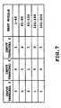
- the block selection signal 304 is input as shown in Fig. 7.
- Five output terminals of the decoder 314 are connected to the AND circuit 307 per the segments S(1) to S(m), separately.
- the first output terminal is connected to the AND circuits 307 of the segments S(1) to S(40) corresponding to nozzle numbers 1 to 40, respectively.
- the second output terminal is connected to the AND circuits 307 of the segments S(41) to S(80) corresponding to nozzle numbers 41 to 80, respectively
- the third output terminal is connected to the AND circuits 307 of the segments S(81) to S(120) corresponding to nozzle numbers 81 to 120, respectively
- the fourth output terminal is connected to the AND circuits 307 of the segments S(121) to S(160) corresponding to nozzle numbers 121 to 160, respectively
- the fifth output terminal is connected to the AND circuits 307 of the segments S(161) to S(200) corresponding to nozzle numbers 161 to 200, respectively.
- nozzle groups of the five blocks separately connected to five output terminals of the decoder 314 are selected as heat nozzles ejecting the ink. Accordingly, ejection timing of the ink can be controlled per the five blocks of nozzle groups.
- circuit elements in Fig. 3 are formed on a Si substrate by semiconductor technology. Furthermore, a head acting portion 108 shown in Fig. 1 is formed on the same substrate.
- Fig. 4 shows a diagrammatic section of the section cutting the primary element long longitudinal axis, in Fig. 3.
- a P-MOS 450 is formed on a N-type well region 402 by impurity implantation, such as ion implantation or the like and diffusion employing a general MOS process.
- a N-MOS 451 is formed on a P-type well region 403, a N-MOS 451 is formed.
- Each of the P-MOS 450 and the N-MOS 451 is constructed with a gate wiring 415 of poly-Si (polycrystalline silicon) deposited in a thickness more than or equal to 4000 ⁇ and less than or equal to 5000 ⁇ by CVD method via a gate insulation layer 408 of the thickness of several hundreds ⁇ , a source region 405 and a drain region 406 doped with N type or P type impurity.
- a C-MOS logic circuit is constructed.
- the N-MOS transistor 301 for driving elements is constructed with a drain region 411, a source region 412 and a gate wiring 413.
- the drain region 411 and the source region 412 are formed on the P-type well region 402 formed by a process of impurity implantation, diffusion and the like.
- a distance L between drain gates forming one transistor becomes about 10 ⁇ m at the minimum value.
- Breakdown of 10 ⁇ m is the width of two contacts 417 of the source and drain.
- the width of two contacts 417 is 2 ⁇ 2 ⁇ m. These contact 417 become common to adjacent transistors. Accordingly, a width of 2 ⁇ m of 1/2 of the width of 2 ⁇ 2 ⁇ m is included in the distance L.
- the distance L becomes 10 ⁇ m.
- an oxide film isolation region 453 is formed by field oxidation in the thickness more than or equal to 5000 ⁇ and less than or equal to 10000 ⁇ , and the elements are isolated.
- the field oxide layer acts as heat accumulation layer 414 of first layer, below the heat acting portion 108.
- an interlayer insulation layer 416 such as PSG film, BPSG film or the like, is deposited in a thickness about 7000 ⁇ by CVD method. Then, the insulation layer 416 is planarized by heat treatment or the like. Subsequently, via the contact hole, wiring is performed by the contact (Al electrode) 417 by the first wiring layer. Then, an interlayer insulation layer 418 of SiO 2 layer or the like is deposited by plasma CVD method in a thickness more than or equal to 10000 ⁇ and less than or equal to 15000 ⁇ . Also, through a through hole, TaN 0.8 hex layer as the resistor layer 104, in a thickness of about 1000 ⁇ is formed by DC sputtering method. Subsequently, an Al electrodes 105 of a second wiring layer to be the wiring to respective elements 201(1), 201(2),..., 201(n) formed by the resistor layer 104, are formed.
- the protective layer 106 Si 3 N 4 is deposited in a thickness of 10000 ⁇ by plasma CVD method. Also, on the uppermost layer, the anti-cavitation layer 107 of Ta or the like is deposited in the thickness of about 2500 ⁇ .
- the substrate 100 of the printing head constructed as set forth above is formed into an ink-jet printing head 510 by forming ejection openings 500 for ejecting the ink, or the like.
- an ink passage wall 501 is formed on the substrate 100
- the printing head 510 is constructed with the substrate 100 and an upper plate 502.
- the ink for printing is supplied into a common liquid chamber 504 of the printing head 510 via a supply tube 503 from a not shown storage chamber.
- the ink supplied into the common liquid chamber 504 is supplied into the ink passages 505 by capillary phenomenon, and is stably held by formation of meniscus at the ejection openings 500.
- the ink within the heat generating portion 108 is heated to cause bubbling.
- energy of bubbling ink droplets are ejected from the ejection openings 500.
- the ejection openings 500 are arranged in high density of 400 dpi to form the ink-jet printing head 510 of multi ejection openings.
- Fig. 6 is a general perspective view showing one example of an ink-jet printing apparatus which can utilize the above-mentioned ink-jet printing head 510.
- the reference numeral 601 denotes a printing head constructed similarly to the foregoing ink-jet printing head 510.
- the head 601 is mounted on a carriage 607.
- the carriage 607 is engaged with a spiral groove 606 of a lead screw 605.
- the lead screw 605 is driven in forward and reverse directions by a reversible motor 602 via driving force transmission gears 603 and 604.
- the head 601 is reciprocally moved in the directions of arrows a and b along a guide 608.
- a printing paper P transported over a platen 409 is held on the platen 609 by a paper holding plate 610 along the moving direction of the carriage 607.
- photo-couplers 611 and 612 are arranged in the vicinity of one end of the lead screw 605.
- the photo-couplers 611 and 612 form a home position detecting means which confirm presence of lever 607a of the carriage 607 at their arrangement positions and performs switching of revolution direction of the driving motor 602, and the like.
- the reference numeral 613 denotes a supporting member for supporting a cap member 614 covering the front face where the ejection openings of the ink-jet printing head 601 are formed.
- the ink not contributing printing of the image is ejected (non-print ejection).
- the non-print ejection is performed in order to maintain the ink ejection performance of the head 601.
- the reference numeral 615 is an ink suction means for sucking an ink accumulated within the cap member 614 by the non-print ejection and the like. By this suction means 615, suction recovery is performed via an opening portion 616 of the cap member 614 for sucking ink from the ejection openings in order to maintain the ink ejection performance of the head 601.
- the reference numeral 617 denotes a cleaning blade
- 618 denotes a moving member which can move the blade 617 in back and forth direction (direction perpendicular to the moving direction of the carriage 607). These blade 617 and the moving member 618 are supported by a main body support body 619.
- the blade 617 is not specified to the shown form but can be of any known cleaning blade.
- the reference numeral 620 denotes a lever for initiating suction of the suction recovery, which is moved by a driving force from the driving motor 602 via a known transmission means, such as a cam 621, clutch or the like.
- An ink-jet printing control portion for providing signals to the heating elements 201(1), 202(2),..., 202(n) within the ink passage 505 of the head 601(see Fig. 5), or performing driving control of respective of foregoing mechanisms, is provided at the main body side of the printing apparatus of Fig. 6, which printing control portion is not shown.
- printing is performed by reciprocally moving the head 601 over the entire width of the paper P.
- the present invention includes a plurality of heating elements for each of ink ejection openings and can obtain high gradation expression ability by selecting these for driving. Also, by providing wiring for a plurality of heating elements in common circuit construction can be simplified and downsizing of the head can be achieved.
- Fig. 8 is a plan view of the major portion of the second embodiment of the element substrate in the ink-jet printing head of the present invention, in which a multi-value heater is arranged utilizing the construction of the substrate of Fig. 1.
- the multi-value heater includes a heating resistor 701 as a component of Fig. 1.
- n in number of heating elements 701(1), 701(2),..., 701(n) are formed.
- These heating elements 701(1), 701(2),..., 701(n) form a one set of segment S.
- the segment S is for one nozzle.
- Interval between n in number of heating elements 701(1), 701(2),..., 701(n) forming the multi-value heater is several ⁇ m.
- one end of the elements 701(1), 701(2),..., 701(n) is connected to the same driving transistors 702(1), 702(2),..., 702(m) via a diode D as shown in Fig. 9.
- the reference numerals 703(1)... 703(m) are electrode wiring for supplying power to respective elements 701(1)... 701(n).
- Fig. 9 is an equivalent circuit of an electric circuit formed by the substrate shown in Fig. 8. Like components to those in Fig. 3 will be identified like reference numerals and the description thereof will be neglected for simplification of disclosure.
- the reference numerals 704(1)... 704(n) are transistors operated by control signal C. With respect to the elements 701(1)... 701(n) of the segments S(1)... S(m), the heater driving voltages VH1... VH(n) can be applied by the transistors. The voltages VH1... VH(n) are set at voltages corresponding to the heat generation amount of the elements 701(1)... 701(n).
- the present invention includes a plurality of heating elements for each of ink ejection openings and can obtain high gradation expression ability by selecting these for driving. Also, by providing wiring for a plurality of heating elements in common circuit construction can be simplified and downsizing of the head can be achieved.
- the select signal 305 is Select 1, 2
- the wiring for the output terminal of the decoder 314 is modified, the printing head of total 160 nozzles having heaters 2a and 2b as respective large and small heating elements, is controlled.
- the number nozzles corresponds to number of the segment S. In case of 160 nozzles, number of segments S becomes 160 of S(1) to S(160).
- the Select 1 of the select signal 305 is input to the AND circuit 307 corresponding to respective heater 2a of the segments S(1) to S(160).
- the Select 2 is input to the AND circuit 307 corresponding to respective heater 2b of the segments S(1) to S(160).
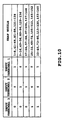
- the block selection signal 304 is input to the input terminals 1, 2 and 3 of the decoder 314, as shown in Fig. 10.
- the five output terminals of the decoder 314 are separately connected to respective the AND circuits 307 per the segments S(1) to S(160).
- the first output terminal is connected to respective of the AND circuits 307 of the segments S corresponding to the nozzle numbers 1 to 8, 41 to 48, 81 to 88 and 121 to 128.
- the second output terminal is connected to respective of the AND circuits 307 of the segments S corresponding to the nozzle numbers 9 to 16, 49 to 56, 89 to 96 and 129 to 136.
- the third output terminal is connected to respective of the AND circuits 307 of the segments S corresponding to the nozzle numbers 17 to 24, 57 to 64, 97 to 104 and 137 to 144.
- the fourth output terminal is connected to respective of the AND circuits 307 of the segments S corresponding to the nozzle numbers 25 to 32, 65 to 72, 105 to 112 and 145 to 152.
- the fifth output terminal is connected to respective of the AND circuits 307 of the segments S corresponding to the nozzle numbers 33 to 40, 73 to 80, 113 to 120 and 153 to 160.
- Figs. 11A to 11C show examples of ink ejection.
- heater 201 for one nozzle heaters 2a and 2b having different heat generation amount are provided.
- the heater 2a having large heat generation amount will be referred to as “large ejection heater”
- the heater 2b having small heat generation amount will be referred to as “small ejection heater”.
- Figs. 11A to 11C the ink is filled in the ejection nozzle defined by the nozzle wall 19.
- the ink is heated to cause bubbling by ejection heaters 2a and 2b.
- the ink is ejected from the orifice 40 by bubbling pressure.
- Fig. 11B shows a condition where the ink is heated to generate bubble by the small ejection heater 2b and a small droplet 14 of the ink is ejected by a small bubble 13. At this time, the ink ejection amount becomes about 20 ng.
- Fig. 11C shows the condition where the ink is heated and bubbled by the small ejection heater 2b and the large ejection heater 2a.
- the ink ejection amount becomes 80 ng.
- a large droplet 16 of the ink is ejected by the small bubble 13 and the large bubble 12.
- the large bubble 12 is generated by the large ejection heater 2a.
- the ink ejection amount 20 ng is adapted to high printing density of 720 dpi, and the ink ejection amount 80 ng is adapted to printing density of 360 dpi.
- Figs. 12 and 13 are explanatory illustrations of hitting positions of the ink droplet on a printing medium S in case of printing of image at printing densities of 360 dpi and 720 dpi in a scanning system employing the printing apparatus 600 shown in Fig. 6, respectively.
- H denotes a printing head forming an image on the printing medium S by scanning in the arrow direction.
- number of nozzle is assumed to be 80 and ink ejection timing is controlled by dividing the nozzles into 10 blocks respectively having 8 nozzles.
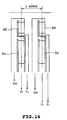
- Fig. 14 shows another example of the arrangement of the heating elements.
- the foregoing heaters 2a and 2b are arranged along the ink ejection direction (upward in Fig. 14).
- One end side of the heaters 2a and 2b are connected to the side of the heater driving power source 309 (see Fig. 3) of the power source voltage VH via the common wiring.
- the other end sides of the heaters 2a and 2b are connected to the side of the corresponding driving transistor 201 (shown as "Tr" in Fig. 14).
- the aligning direction of the heating element vertical direction of Fig. 14
- the aligning direction of the transistors 201 lateral direction of Fig. 14
- alignment direction of the heating elements and the aligning direction of the transistors become parallel.
- the present invention achieves distinct effect when applied to a recording head or a recording apparatus which has means for generating thermal energy such as electrothermal transducers or laser light, and which causes changes in ink by the thermal energy so as to eject ink. This is because such a system can achieve a high density and high resolution recording.
- the on-demand type apparatus has electrothermal transducers, each disposed on a sheet or liquid passage that retains liquid (ink), and operates as follows: first, one or more drive signals are applied to the electrothermal transducers to cause thermal energy corresponding to recording information; second, the thermal energy induces sudden temperature rise that exceeds the nucleate boiling so as to cause the film boiling on heating portions of the recording head; and third, bubbles are grown in the liquid (ink) corresponding to the drive signals. By using the growth and collapse of the bubbles, the ink is expelled from at least one of the ink ejection orifices of the head to form one or more ink drops.
- the drive signal in the form of a pulse is preferable because the growth and collapse of the bubbles can be achieved instantaneously and suitably by this form of drive signal.
- a drive signal in the form of a pulse those described in U.S. patent Nos. 4,463,359 and 4,345,262 are preferable.
- the rate of temperature rise of the heating portions described in U.S. patent No. 4,313,124 be adopted to achieve better recording.
- U.S. patent Nos. 4,558,333 and 4,459,600 disclose the following structure of a recording head, which is incorporated to the present invention: this structure includes heating portions disposed on bent portions in addition to a combination of the ejection orifices, liquid passages and the electrothermal transducers disclosed in the above patents.
- this structure includes heating portions disposed on bent portions in addition to a combination of the ejection orifices, liquid passages and the electrothermal transducers disclosed in the above patents.
- the present invention can achieve recording positively and effectively.
- the present invention can be also applied to a so-called full-line type recording head whose length equals the maximum length across a recording medium.
- a recording head may consists of a plurality of recording heads combined together, or one integrally arranged recording head.
- the present invention can be applied to various serial type recording heads: a recording head fixed to the main assembly of a recording apparatus; a conveniently replaceable chip type recording head which, when loaded on the main assembly of a recording apparatus, is electrically connected to the main assembly, and is supplied with ink therefrom; and a cartridge type recording head integrally including an ink reservoir.
- a recovery system or a preliminary auxiliary system for a recording head as a constituent of the recording apparatus because they serve to make the effect of the present invention more reliable.
- the recovery system are a capping means and a cleaning means for the recording head, and a pressure or suction means for the recording head.
- the preliminary auxiliary system are a preliminary heating means utilizing electrothermal transducers or a combination of other heater elements and the electrothermal transducers, and a means for carrying out preliminary ejection of ink independently of the ejection for recording. These systems are effective for reliable recording.
- the number and type of recording heads to be mounted on a recording apparatus can be also changed. For example, only one recording head corresponding to a single color ink, or a plurality of recording heads corresponding to a plurality of inks different in color or concentration can be used.
- the present invention can be effectively applied to an apparatus having at least one of the monochromatic, multi-color and full-color modes.
- the monochromatic mode performs recording by using only one major color such as black.
- the multi-color mode carries out recording by using different color inks, and the full-color mode performs recording by color mixing.
- inks that are liquid when the recording signal is applied can be used: for example, inks can be employed that solidify at a temperature lower than the room temperature and are softened or liquefied in the room temperature. This is because in the ink jet system, the ink is generally temperature adjusted in a range of 30°C - 70°C so that the viscosity of the ink is maintained at such a value that the ink can be ejected reliably.
- the present invention can be applied to such apparatus where the ink is liquefied just before the ejection by the thermal energy as follows so that the ink is expelled from the orifices in the liquid state, and then begins to solidify on hitting the recording medium, thereby preventing the ink evaporation: the ink is transformed from solid to liquid state by positively utilizing the thermal energy which would otherwise cause the temperature rise; or the ink, which is dry when left in air, is liquefied in response to the thermal energy of the recording signal.
- the ink may be retained in recesses or through holes formed in a porous sheet as liquid or solid substances so that the ink faces the electrothermal transducers as described in Japanese Patent Application Laying-open Nos. 56847/1979 or 71260/1985.
- the present invention is most effective when it uses the film boiling phenomenon to expel the ink.
- the ink jet recording apparatus of the present invention can be employed not only as an image output terminal of an information processing device such as a computer, but also as an output device of a copying machine including a reader, and as an output device of a facsimile apparatus having a transmission and receiving function.
Landscapes
- Particle Formation And Scattering Control In Inkjet Printers (AREA)
- Ink Jet (AREA)
Claims (45)
- Substrat für einen Tintenstrahldruckkopf zum Ausstoß von Tinte durch eine Vielzahl von Ausstoßöffnungen, mitHeizelementen (201(1) .. 201(n)) zum Erzeugen von Wärmeenergie, um den Ausstoß von Tinte zu veranlassen, wobei die Heizelemente so angeordnet sind, dass sie für jede aus der Vielzahl von Ausstoßöffnungen eine entsprechende Vielzahl von Heizelementen bereitstellen,einer M-bit Datenwarteschaltung (303) zum Halten von Bilddaten für die Ansteuerung der Heizelemente, wobei M gleich der Anzahl der Ausstoßöffnungen ist;einer Auswahlschaltung (307) zum Empfangen der durch jede der Ausstoßöffnungen aufzuzeichnenden Bilddaten von der Datenwarteschaltung (303) und zum Auswählen eines oder mehrerer aus der Vielzahl von mit dieser anzusteuernden Ausstoßöffnung verknüpften Heizelementen für jede Ausstoßöffnung; undeiner Ansteuerungsschaltung (301) für jede Ausstoßöffnung für die Ansteuerung des oder jedes durch die Auswahlschaltung (307) ausgewählten Heizelements.
- Substrat für einen Tintenstrahldruckkopf nach Anspruch 1, wobei die Datenwarteschaltung (303) und die Auswahlschaltung (307) in dem Substrat für den Tintenstrahldruckkopf integriert eingebaut sind.
- Substrat für einen Tintenstrahldruckkopf nach einem der Ansprüche 1 oder 2, wobei die Ansteuerungsschaltung (301) eine Vielzahl von Ansteuerelementen (301) umfasst, die auf einer Eins-zu-Eins-Grundlage bezüglich der Vielzahl von Heizelementen bereitgestellt werden.
- Substrat für einen Tintenstrahldruckkopf nach einem der Ansprüche 1 bis 3, wobei die Auswahlschaltung (307) in der Lage ist, jede aus einer Vielzahl von Gruppen von Ausstoßöffnungen auszuwählen, um das Ansteuern eines oder mehrerer aus der Vielzahl der mit jeder Ausstoßöffnung der ausgewählten Gruppe verknüpften Heizelemente (201(1)...201(n)) freizugeben.
- Substrat für einen Tintenstrahldruckkopf nach einem der vorstehenden Ansprüche, wobei die Enden von jedem Heizelement (201(1)...201(n)) elektrisch mit der Leiterbahn für eine Energieversorgung verbunden sind.
- Substrat für einen Tintenstrahldruckkopf nach Anspruch 5, wobei die Leiterbahn für eine Energieversorgung ein Schaltelement aufweist, das abhängig von einem Steuersignal für die Ansteuerung der Heizelemente (201(1)...201(n)) betrieben werden kann.
- Substrat für einen Tintenstrahldruckkopf nach einem der vorstehenden Ansprüche, ferner mit einer gemeinsamen Leiterbahn, die elektrisch mit der Vielzahl von Heizelementen (201(1)...201(n)) verbunden ist, wobei die gemeinsame Leiterbahn ein Schaltelement aufweist, das abhängig von einem Ansteuersignal für die Ansteuerung der Heizelemente (201(1)...201(n)) betrieben werden kann.
- Substrat für einen Tintenstrahldruckkopf nach einem der vorstehenden Ansprüche, wobei die für jede Ausstoßöffnung bereitgestellte Vielzahl von Heizelementen sich voneinander durch den Betrag der erzeugten Wärme unterscheidet.
- Substrat für einen Tintenstrahldruckkopf nach Anspruch 8, wobei die Vielzahl von Heizelementen (201(1)...201(n)) einen Leiterbahnverbindungsabschnitt mit einem von dem jeweils erzeugten Wärmemenge abhängigen Bereich aufweisen.
- Substrat für einen Tintenstrahldruckkopf nach einem der vorstehenden Ansprüche, wobei die Ansteuerungsschaltung (301) einen N-MOS Transistor (301) umfasst.
- Substrat für einen Tintenstrahldruckkopf nach einem der vorstehenden Ansprüche, wobei die Auswahlschaltung (307) eine Schaltung für die Zufuhr eines Auswahlsignals ist, das entsprechenden aus der Vielzahl von Heizelementen (201(1)...201(n)) für jede der Ausstoßöffnungen entspricht.
- Substrat für einen Tintenstrahldruckkopf nach einem der vorstehenden Ansprüche, wobei die Auswahlschaltung (307) eine Schaltung ist, die ein Auswahlsignal in Abhängigkeit von der Druckdichte des zu druckenden Bildes zuführt.
- Substrat für einen Tintenstrahldruckkopf nach einem der vorstehenden Ansprüche, wobei die Ansteuerungsschaltung (301) eine Vielzahl von Ansteuerelementen (301) umfasst, die entlang der Ausrichtung der Heizelemente (201(1)...201(n)) angeordnet sind.
- Substrat für einen Tintenstrahldruckkopf nach einem der Ansprüche 1 bis 12, dadurch gekennzeichnet, dass die Ansteuerungsschaltung (301) eine Vielzahl von Ansteuerelementen (301) umfasst, die in einer Richtung ausgerichtet sind, die sich mit der Ausrichtung der Heizelemente (201(1)...201(n)) schneidet.
- Substrat für einen Tintenstrahldruckkopf nach einem der vorstehenden Ansprüche, wobei jedes der Heizelemente (201(1)...201(n)) ein elektrothermischer Wandler ist.
- Tintenstrahldruckkopf zum Ausstoß von Tinte durch ein Vielzahl von Ausstoßöffnungen, miteiner Vielzahl von Durchgängen, von denen jeder mit der jeweiligen der Ausstoßöffnungen in Verbindung steht, und einem Substrat mit:Heizelementen (201(1) .. 201(n)) zum Erzeugen von Wärmeenergie, um den Ausstoß von Tinte zu veranlassen, wobei die Heizelemente so angeordnet sind, dass sie für jede aus der Vielzahl von Ausstoßöffnungen eine entsprechende Vielzahl von Heizelementen bereitstellen,einer M Bit Datenwarteschaltung (303) zum Halten von Bilddaten für die Ansteuerung der Heizelemente, wobei M gleich der Anzahl der Ausstoßöffnungen ist;einer Auswahlschaltung (307) zum Empfangen der durch jede der Ausstoßöffnungen aufzuzeichnenden Bilddaten von der Datenwarteschaltung (303) und zum Auswählen eines oder mehrerer aus der Vielzahl von mit dieser anzusteuernden Ausstoßöffnung verknüpften Heizelementen für jede Ausstoßöffnung; undeiner Ansteuerungsschaltung (301) für die Ansteuerung des oder jedes Heizelements, das von der Auswahlschaltung (307) für jede Ausstoßöffnung ausgewählt wurde.
- Tintenstrahldruckkopf nach Anspruch 16, wobei die Datenwarteschaltung (303) und die Auswahlschaltung (307) in dem Substrat integriert eingebaut sind.
- Tintenstrahldruckkopf nach einem der Ansprüche 16 oder 17, wobei die Ansteuerungsschaltung (301) eine Vielzahl von Ansteuerelementen (301) umfasst, die auf einer Eins-zu-Eins-Grundlage bezüglich der Vielzahl von Heizelementen bereitgestellt werden.
- Tintenstrahldruckkopf nach einem der Ansprüche 16 bis 18, wobei die Auswahlschaltung (307) in der Lage ist, jede aus einer Vielzahl von Gruppen von Ausstoßöffnungen auszuwählen, um das Ansteuern eines oder mehrerer aus der Vielzahl der mit jeder Ausstoßöffnung der ausgewählten Gruppe verknüpften Heizelemente (201(1)...201(n)) freizugeben.
- Tintenstrahldruckkopf nach einem der Ansprüche 16 bis 19, wobei die Enden von jedem Heizelement (201(1)...201(n)) elektrisch mit der Leiterbahn für eine Energieversorgung verbunden sind.
- Tintenstrahldruckkopf nach Anspruch 20, wobei die Leiterbahn für eine Energieversorgung ein Schaltelement aufweist, das abhängig von einem Steuersignal für die Ansteuerung der Heizelemente (201(1)...201(n)) betrieben werden kann.
- Tintenstrahldruckkopf nach einem der Ansprüche 16 bis 21, ferner mit einer gemeinsamen Leiterbahn, die elektrisch mit der Vielzahl von Heizelementen (201(1)...201(n)) verbunden ist, wobei die gemeinsame Leiterbahn ein Schaltelement aufweist, das abhängig von einem Ansteuersignal für die Ansteuerung der Heizelemente (201(1)...201(n)) betrieben werden kann.
- Tintenstrahldruckkopf nach einem der Ansprüche 16 bis 22, wobei die für jede Ausstoßöffnung bereitgestellte Vielzahl von Heizelementen sich voneinander durch den Betrag der erzeugten Wärme unterscheidet.
- Tintenstrahldruckkopf nach Anspruch 23, wobei die Vielzahl von Heizelementen (201(1)...201(n)) einen Leiterbahnverbindungsabschnitt mit einem von dem jeweils erzeugten Wärmemenge abhängigen Bereich aufweisen.
- Tintenstrahldruckkopf nach einem der Ansprüche 16 bis 24, wobei die Ansteuerungsschaltung (301) einen N-MOS Transistor (301) umfasst.
- Tintenstrahldruckkopf nach einem der Ansprüche 16 bis 25, wobei die Auswahlschaltung (307) eine Schaltung für die Zufuhr eines Auswahlsignals ist, das entsprechenden aus der Vielzahl von Heizelementen (201(1)...201(n)) für jede der Ausstoßöffnungen entspricht.
- Tintenstrahldruckkopf nach einem der Ansprüche 16 bis 26, wobei die Auswahlschaltung (307) eine Schaltung ist, die ein Auswahlsignal in Abhängigkeit von der Druckdichte des zu druckenden Bildes zuführt.
- Tintenstrahldruckkopf nach einem der Ansprüche 16 bis 27, wobei die Ansteuerungsschaltung (301) eine Vielzahl von Ansteuerelementen (301) umfasst, die entlang der Ausrichtung der Heizelemente (201(1)...201(n)) angeordnet sind.
- Tintenstrahldruckkopf nach einem der Ansprüche 16 bis 27, dadurch gekennzeichnet, dass die Ansteuerungsschaltung (301) eine Vielzahl von Ansteuerelementen (301) umfasst, die in einer Richtung ausgerichtet sind, die sich mit der Ausrichtung der Heizelemente (201(1)...201(n)) schneidet.
- Tintenstrahldruckkopf nach einem der Ansprüche 16 bis 29, wobei jedes der Heizelemente (201(1)...201(n)) ein elektrothermischer Wandler ist.
- Tintenstrahl-Druckvorrichtung, die einen Tintenstrahldruckkopf zum Ausstoßen von Tinte durch eine Vielzahl von Ausstoßöffnungen zum Drucken eines Bildes auf einem Druckträger verwendet, miteiner Einrichtung, um den Druckkopf und den Druckträger relativ zueinander zu bewegen;dem Tintenstrahldruckkopf, der eine Vielzahl von Durchgängen, von denen jede mit der jeweiligen der Ausstoßöffnungen in Verbindung steht, und ein Substrat umfasst mit:Heizelementen (201(1) .. 201(n)) zum Erzeugen von Wärmeenergie, um den Ausstoß von Tinte zu veranlassen, wobei die Heizelemente so angeordnet sind, dass sie für jede aus der Vielzahl von Ausstoßöffnungen eine entsprechende Vielzahl von Heizelementen bereitstellen,einer M Bit Datenwarteschaltung (303) zum Halten von Bilddaten für die Ansteuerung der Heizelemente, wobei M gleich der Anzahl der Ausstoßöffnungen ist;einer Auswahlschaltung (307) zum Empfangen der durch jede der Ausstoßöffnungen aufzuzeichnenden Bilddaten von der Datenwarteschaltung (303) und zum Auswählen eines oder mehrerer aus der Vielzahl von mit dieser anzusteuernden Ausstoßöffnung verknüpften Heizelementen für jede Ausstoßöffnung; undeiner Ansteuerungsschaltung (301) für die Ansteuerung des oder jedes Heizelements, das von der Auswahlschaltung (307) für jede Ausstoßöffnung ausgewählt wurde.
- Tintenstrahl-Druckvorrichtung nach Anspruch 31, wobei die Datenwarteschaltung (303) und die Auswahlschaltung (307) in dem Substrat integriert eingebaut sind.
- Tintenstrahl-Druckvorrichtung nach einem der Ansprüche 31 oder 32, wobei die Ansteuerungsschaltung (301) eine Vielzahl von Ansteuerelementen (301) umfasst, die auf einer Eins-zu-Eins-Grundlage bezüglich der Vielzahl von Heizelementen bereitgestellt werden.
- Tintenstrahl-Druckvorrichtung nach einem der Ansprüche 31 bis 33, wobei die Auswahlschaltung (307) in der Lage ist, jede aus einer Vielzahl von Gruppen von Ausstoßöffnungen auszuwählen, um das Ansteuern eines oder mehrerer aus der Vielzahl der mit jeder Ausstoßöffnung der ausgewählten Gruppe verknüpften Heizelemente (201(1)...201(n)) freizugeben.
- Tintenstrahl-Druckvorrichtung nach einem der Ansprüche 31 bis 34, wobei die Enden von jedem Heizelement (201(1)...201(n)) elektrisch mit der Leiterbahn für eine Energieversorgung verbunden sind.
- Tintenstrahl-Druckvorrichtung nach Anspruch 35, wobei die Leiterbahn für eine Energieversorgung ein Schaltelement aufweist, das abhängig von einem Steuersignal für die Ansteuerung der Heizelemente (201(1)...201(n)) betrieben werden kann.
- Tintenstrahl-Druckvorrichtung nach einem der Ansprüche 31 bis 36, ferner mit einer gemeinsamen Leiterbahn, die elektrisch mit der Vielzahl von Heizelementen (201(1)...201(n)) verbunden ist, wobei die gemeinsame Leiterbahn ein Schaltelement aufweist, das abhängig von einem Ansteuersignal für die Ansteuerung der Heizelemente (201(1)...201(n)) betrieben werden kann.
- Tintenstrahl-Druckvorrichtung nach einem der Ansprüche 31 bis 37, wobei die für jede Ausstoßöffnung bereitgestellte Vielzahl von Heizelementen sich voneinander durch den Betrag der erzeugten Wärme unterscheidet.
- Tintenstrahl-Druckvorrichtung nach Anspruch 38, wobei die Vielzahl von Heizelementen (201(1)...201(n)) einen Leiterbahnverbindungsabschnitt mit einem von dem jeweils erzeugten Wärmemenge abhängigen Bereich aufweisen.
- Tintenstrahl-Druckvorrichtung nach einem der Ansprüche 31 bis 39, wobei die Ansteuerungsschaltung (301) einen N-MOS Transistor (301) umfasst.
- Tintenstrahl-Druckvorrichtung nach einem der Ansprüche 31 bis 40, wobei die Auswahlschaltung (307) eine Schaltung für die Zufuhr eines Auswahlsignals ist, das entsprechenden aus der Vielzahl von Heizelementen (201(1)...201(n)) für jede der Ausstoßöffnungen entspricht.
- Tintenstrahl-Druckvorrichtung nach einem der Ansprüche 31 bis 41, wobei die Auswahlschaltung (307) eine Schaltung ist, die ein Auswahlsignal in Abhängigkeit von der Druckdichte des zu druckenden Bildes zuführt.
- Tintenstrahl-Druckvorrichtung nach einem der Ansprüche 31 bis 42, wobei die Ansteuerungsschaltung (301) eine Vielzahl von Ansteuerelementen (301) umfasst, die entlang der Ausrichtung der Heizelemente (201(1)...201(n)) angeordnet sind.
- Tintenstrahl-Druckvorrichtung nach einem der Ansprüche 31 bis 42, dadurch gekennzeichnet, dass die Ansteuerungsschaltung (301) eine Vielzahl von Ansteuerelementen (301) umfasst, die in einer Richtung ausgerichtet sind, die sich mit der Ausrichtung der Heizelemente (201(1)...201(n)) schneidet.
- Tintenstrahl-Druckvorrichtung nach einem der Ansprüche 31 bis 44, wobei jedes der Heizelemente (201(1)...201(n)) ein elektrothermischer Wandler ist.
Applications Claiming Priority (3)
| Application Number | Priority Date | Filing Date | Title |
|---|---|---|---|
| JP10057496 | 1996-04-22 | ||
| JP8100574A JPH09286108A (ja) | 1996-04-22 | 1996-04-22 | インクジェットプリントヘッドの基体、インクジェットプリントヘッド、およびインクジェットプリント装置 |
| JP100574/96 | 1996-04-22 |
Publications (3)
| Publication Number | Publication Date |
|---|---|
| EP0805029A2 EP0805029A2 (de) | 1997-11-05 |
| EP0805029A3 EP0805029A3 (de) | 1998-06-24 |
| EP0805029B1 true EP0805029B1 (de) | 2002-03-20 |
Family
ID=14277678
Family Applications (1)
| Application Number | Title | Priority Date | Filing Date |
|---|---|---|---|
| EP97302612A Expired - Lifetime EP0805029B1 (de) | 1996-04-22 | 1997-04-16 | Substrat für ein Element eines Tintenstrahldruckkopfes, Tintenstrahldruckkopf und Tintenstrahldruckapparat |
Country Status (4)
| Country | Link |
|---|---|
| US (1) | US6450616B1 (de) |
| EP (1) | EP0805029B1 (de) |
| JP (1) | JPH09286108A (de) |
| DE (1) | DE69711111T2 (de) |
Cited By (1)
| Publication number | Priority date | Publication date | Assignee | Title |
|---|---|---|---|---|
| SG141213A1 (en) * | 2002-08-20 | 2008-04-28 | Sony Corp | Liquid ejecting device and liquid ejecting method |
Families Citing this family (6)
| Publication number | Priority date | Publication date | Assignee | Title |
|---|---|---|---|---|
| US6137502A (en) * | 1999-08-27 | 2000-10-24 | Lexmark International, Inc. | Dual droplet size printhead |
| US6623700B1 (en) * | 2000-11-22 | 2003-09-23 | Xerox Corporation | Level sense and control system for biofluid drop ejection devices |
| US6616268B2 (en) * | 2001-04-12 | 2003-09-09 | Lexmark International, Inc. | Power distribution architecture for inkjet heater chip |
| US6966629B2 (en) * | 2002-07-18 | 2005-11-22 | Canon Kabushiki Kaisha | Inkjet printhead, driving method of inkjet printhead, and substrate for inkjet printhead |
| CN1968815B (zh) * | 2004-06-28 | 2013-05-01 | 佳能株式会社 | 排液头制造方法,和使用该方法得到的排液头 |
| JP4669278B2 (ja) * | 2004-12-27 | 2011-04-13 | キヤノン株式会社 | 記録ヘッド用素子基板、記録ヘッドおよび記録装置 |
Family Cites Families (30)
| Publication number | Priority date | Publication date | Assignee | Title |
|---|---|---|---|---|
| CA1127227A (en) | 1977-10-03 | 1982-07-06 | Ichiro Endo | Liquid jet recording process and apparatus therefor |
| JPS5459936A (en) | 1977-10-03 | 1979-05-15 | Canon Inc | Recording method and device therefor |
| JPS5936879B2 (ja) | 1977-10-14 | 1984-09-06 | キヤノン株式会社 | 熱転写記録用媒体 |
| US4330787A (en) | 1978-10-31 | 1982-05-18 | Canon Kabushiki Kaisha | Liquid jet recording device |
| DE2945658A1 (de) | 1978-11-14 | 1980-05-29 | Canon Kk | Fluessigkeitsstrahl-aufzeichnungsverfahren |
| US4345262A (en) | 1979-02-19 | 1982-08-17 | Canon Kabushiki Kaisha | Ink jet recording method |
| US4463359A (en) | 1979-04-02 | 1984-07-31 | Canon Kabushiki Kaisha | Droplet generating method and apparatus thereof |
| US4313124A (en) | 1979-05-18 | 1982-01-26 | Canon Kabushiki Kaisha | Liquid jet recording process and liquid jet recording head |
| JPS5772867A (en) | 1980-10-23 | 1982-05-07 | Canon Inc | Liquid injecting recording apparatus |
| JPS5772868A (en) | 1980-10-23 | 1982-05-07 | Canon Inc | Liquid injecting recording apparatus |
| US4558333A (en) | 1981-07-09 | 1985-12-10 | Canon Kabushiki Kaisha | Liquid jet recording head |
| JPS59123670A (ja) | 1982-12-28 | 1984-07-17 | Canon Inc | インクジエツトヘツド |
| JPS59138461A (ja) | 1983-01-28 | 1984-08-08 | Canon Inc | 液体噴射記録装置 |
| JPS6071260A (ja) | 1983-09-28 | 1985-04-23 | Erumu:Kk | 記録装置 |
| GB2166619B (en) * | 1984-09-28 | 1988-12-07 | Canon Kk | Image processing apparatus |
| JPS61106259A (ja) | 1984-10-31 | 1986-05-24 | Hitachi Ltd | インク滴噴出装置 |
| JPS6248585A (ja) | 1985-08-28 | 1987-03-03 | Sony Corp | 感熱記録紙 |
| US4947192A (en) | 1988-03-07 | 1990-08-07 | Xerox Corporation | Monolithic silicon integrated circuit chip for a thermal ink jet printer |
| US5081474A (en) | 1988-07-04 | 1992-01-14 | Canon Kabushiki Kaisha | Recording head having multi-layer matrix wiring |
| JPH02239940A (ja) | 1989-03-14 | 1990-09-21 | Nec Corp | インクジェットヘッド |
| JP2836749B2 (ja) | 1989-05-09 | 1998-12-14 | 株式会社リコー | 液体噴射記録ヘッド |
| AU635562B2 (en) | 1989-09-18 | 1993-03-25 | Canon Kabushiki Kaisha | Recording head with cover |
| US5479196A (en) | 1990-02-26 | 1995-12-26 | Canon Kabushiki Kaisha | Ink jet recording apparatus and method of recovery ink discharging condition of the same |
| EP0525787B1 (de) * | 1991-08-01 | 1996-10-16 | Canon Kabushiki Kaisha | Aufzeichnungskopfherstellungsverfahren |
| JPH06126964A (ja) | 1992-10-16 | 1994-05-10 | Canon Inc | インクジェットヘッドおよび該インクジェットヘッドを備えたインクジェット記録装置 |
| JPH0766949A (ja) * | 1993-08-24 | 1995-03-10 | Canon Inc | ファクシミリ装置 |
| JPH07148964A (ja) | 1993-11-30 | 1995-06-13 | Kyocera Corp | サーマルヘッド |
| JPH07290707A (ja) | 1994-04-22 | 1995-11-07 | Canon Inc | 記録ヘッド及び該記録ヘッドを用いたプリンタ装置及びプリント方法 |
| JP3086132B2 (ja) | 1994-07-29 | 2000-09-11 | キヤノン株式会社 | インクジェット記録装置 |
| JPH08118641A (ja) * | 1994-10-20 | 1996-05-14 | Canon Inc | インクジェットヘッド、インクジェットヘッドカートリッジ、インクジェット装置およびインクが再注入されたインクジェットヘッドカートリッジ用インク容器 |
-
1996
- 1996-04-22 JP JP8100574A patent/JPH09286108A/ja active Pending
-
1997
- 1997-04-11 US US08/843,074 patent/US6450616B1/en not_active Expired - Lifetime
- 1997-04-16 EP EP97302612A patent/EP0805029B1/de not_active Expired - Lifetime
- 1997-04-16 DE DE69711111T patent/DE69711111T2/de not_active Expired - Lifetime
Cited By (1)
| Publication number | Priority date | Publication date | Assignee | Title |
|---|---|---|---|---|
| SG141213A1 (en) * | 2002-08-20 | 2008-04-28 | Sony Corp | Liquid ejecting device and liquid ejecting method |
Also Published As
| Publication number | Publication date |
|---|---|
| EP0805029A3 (de) | 1998-06-24 |
| DE69711111D1 (de) | 2002-04-25 |
| JPH09286108A (ja) | 1997-11-04 |
| EP0805029A2 (de) | 1997-11-05 |
| DE69711111T2 (de) | 2002-09-19 |
| US6450616B1 (en) | 2002-09-17 |
Similar Documents
| Publication | Publication Date | Title |
|---|---|---|
| EP0390202B1 (de) | Tintenstrahlaufzeichnungskopf, Betriebsart und Tintenstrahlaufzeichnungsgerät | |
| KR100980124B1 (ko) | 잉크젯 기록 헤드 | |
| EP0785072B1 (de) | Tintenstrahlkopf, Tintenstrahlkopfpatrone, Tintenstrahlapparat und Tintenstrahlaufzeichnungsverfahren für Gradationsaufzeichnung | |
| EP1359013B1 (de) | Ausstosspulsen in einem Flüssigkeitsausstossgerät | |
| JP4194313B2 (ja) | 記録ヘッド | |
| EP0747221B1 (de) | Tintenstrahlkopf, Tintenstrahlvorrichtung und Tintenstrahlaufzeichnungsverfahren | |
| JPH08252926A (ja) | 記録ヘッド及びその記録ヘッドを用いた記録装置 | |
| JP3387749B2 (ja) | 記録ヘッド及びその記録ヘッドを用いた記録装置 | |
| EP0805029B1 (de) | Substrat für ein Element eines Tintenstrahldruckkopfes, Tintenstrahldruckkopf und Tintenstrahldruckapparat | |
| JP3124696B2 (ja) | 記録ヘッド及びその記録ヘッドを用いた記録装置 | |
| JPH05212876A (ja) | 記録ヘッド用基板及び記録ヘッド及び記録装置 | |
| JPH09254413A (ja) | 階調記録に用いるインクジェットヘッド、インクジェットヘッドカートリッジ、インクジェット装置およびインクジェット記録方法 | |
| JP4474126B2 (ja) | インクジェット記録ヘッド及びインクジェット記録ヘッドの駆動方法 | |
| US6634730B2 (en) | Ink-jet printhead, printing apparatus having said printhead, and method of driving said printhead | |
| JPH09286107A (ja) | インクジェットプリントヘッドの基体、インクジェットプリントヘッド、およびインクジェットプリント装置 | |
| JPH09286106A (ja) | インクジェットプリントヘッドおよびインクジェットプリント装置 | |
| JP2004066601A (ja) | 記録ヘッドとその記録ヘッドを用いた記録装置 | |
| JPH08108538A (ja) | 記録ヘッド及び該記録ヘッドを用いた記録装置 | |
| JP2001162798A (ja) | 液体吐出ヘッド、液体吐出ヘッドカートリッジ、液体吐出装置、および液体吐出方法 | |
| JPH11342611A (ja) | 液体吐出ヘッドおよび液体吐出装置 | |
| JPH09123452A (ja) | インクジェット記録ヘッド用基体、インクジェット記録ヘッドおよびインクジェット記録装置 | |
| JPH11170535A (ja) | 記録ヘッド基体及びそれを用いたインクジェット記録ヘッド及びそれを用いたインクジェット記録装置 | |
| JPH0776082A (ja) | プリントヘッド用基体、プリントヘッドおよびプリント装置 | |
| JPH0890772A (ja) | 記録ヘッド、及び、その記録ヘッドを用いた記録装置 | |
| JPH08290575A (ja) | インクジェット記録ヘッド用基体、インクジェット記録ヘッドおよびインクジェット記録装置 |
Legal Events
| Date | Code | Title | Description |
|---|---|---|---|
| PUAI | Public reference made under article 153(3) epc to a published international application that has entered the european phase |
Free format text: ORIGINAL CODE: 0009012 |
|
| AK | Designated contracting states |
Kind code of ref document: A2 Designated state(s): DE FR GB IT |
|
| PUAL | Search report despatched |
Free format text: ORIGINAL CODE: 0009013 |
|
| AK | Designated contracting states |
Kind code of ref document: A3 Designated state(s): DE FR GB IT |
|
| 17P | Request for examination filed |
Effective date: 19981104 |
|
| 17Q | First examination report despatched |
Effective date: 20000204 |
|
| GRAG | Despatch of communication of intention to grant |
Free format text: ORIGINAL CODE: EPIDOS AGRA |
|
| GRAG | Despatch of communication of intention to grant |
Free format text: ORIGINAL CODE: EPIDOS AGRA |
|
| GRAG | Despatch of communication of intention to grant |
Free format text: ORIGINAL CODE: EPIDOS AGRA |
|
| GRAH | Despatch of communication of intention to grant a patent |
Free format text: ORIGINAL CODE: EPIDOS IGRA |
|
| GRAH | Despatch of communication of intention to grant a patent |
Free format text: ORIGINAL CODE: EPIDOS IGRA |
|
| REG | Reference to a national code |
Ref country code: GB Ref legal event code: IF02 |
|
| GRAA | (expected) grant |
Free format text: ORIGINAL CODE: 0009210 |
|
| AK | Designated contracting states |
Kind code of ref document: B1 Designated state(s): DE FR GB IT |
|
| REF | Corresponds to: |
Ref document number: 69711111 Country of ref document: DE Date of ref document: 20020425 |
|
| ET | Fr: translation filed | ||
| PLBE | No opposition filed within time limit |
Free format text: ORIGINAL CODE: 0009261 |
|
| STAA | Information on the status of an ep patent application or granted ep patent |
Free format text: STATUS: NO OPPOSITION FILED WITHIN TIME LIMIT |
|
| 26N | No opposition filed |
Effective date: 20021223 |
|
| PGFP | Annual fee paid to national office [announced via postgrant information from national office to epo] |
Ref country code: IT Payment date: 20090415 Year of fee payment: 13 Ref country code: FR Payment date: 20090424 Year of fee payment: 13 |
|
| REG | Reference to a national code |
Ref country code: FR Ref legal event code: ST Effective date: 20101230 |
|
| PG25 | Lapsed in a contracting state [announced via postgrant information from national office to epo] |
Ref country code: IT Free format text: LAPSE BECAUSE OF NON-PAYMENT OF DUE FEES Effective date: 20100416 |
|
| PG25 | Lapsed in a contracting state [announced via postgrant information from national office to epo] |
Ref country code: FR Free format text: LAPSE BECAUSE OF NON-PAYMENT OF DUE FEES Effective date: 20100430 |
|
| PGFP | Annual fee paid to national office [announced via postgrant information from national office to epo] |
Ref country code: DE Payment date: 20150430 Year of fee payment: 19 Ref country code: GB Payment date: 20150424 Year of fee payment: 19 |
|
| REG | Reference to a national code |
Ref country code: DE Ref legal event code: R119 Ref document number: 69711111 Country of ref document: DE |
|
| GBPC | Gb: european patent ceased through non-payment of renewal fee |
Effective date: 20160416 |
|
| PG25 | Lapsed in a contracting state [announced via postgrant information from national office to epo] |
Ref country code: GB Free format text: LAPSE BECAUSE OF NON-PAYMENT OF DUE FEES Effective date: 20160416 Ref country code: DE Free format text: LAPSE BECAUSE OF NON-PAYMENT OF DUE FEES Effective date: 20161101 |