EP0804043B1 - Capot de protection pour modules dans la technique des télécommunications - Google Patents
Capot de protection pour modules dans la technique des télécommunications Download PDFInfo
- Publication number
- EP0804043B1 EP0804043B1 EP96119547A EP96119547A EP0804043B1 EP 0804043 B1 EP0804043 B1 EP 0804043B1 EP 96119547 A EP96119547 A EP 96119547A EP 96119547 A EP96119547 A EP 96119547A EP 0804043 B1 EP0804043 B1 EP 0804043B1
- Authority
- EP
- European Patent Office
- Prior art keywords
- module
- modules
- cover
- cover according
- sealing element
- Prior art date
- Legal status (The legal status is an assumption and is not a legal conclusion. Google has not performed a legal analysis and makes no representation as to the accuracy of the status listed.)
- Expired - Lifetime
Links
- 230000001681 protective effect Effects 0.000 title claims description 57
- 238000005516 engineering process Methods 0.000 title claims description 11
- 238000007789 sealing Methods 0.000 claims description 74
- 239000000428 dust Substances 0.000 claims description 33
- 230000000694 effects Effects 0.000 claims description 7
- 239000012466 permeate Substances 0.000 claims 1
- 238000009826 distribution Methods 0.000 description 14
- 239000003570 air Substances 0.000 description 5
- 230000007613 environmental effect Effects 0.000 description 5
- 239000004519 grease Substances 0.000 description 5
- 238000004519 manufacturing process Methods 0.000 description 5
- 230000008021 deposition Effects 0.000 description 4
- 239000012080 ambient air Substances 0.000 description 3
- 238000009833 condensation Methods 0.000 description 3
- 230000005494 condensation Effects 0.000 description 3
- 238000009413 insulation Methods 0.000 description 3
- 238000000926 separation method Methods 0.000 description 3
- 239000000969 carrier Substances 0.000 description 2
- 238000005260 corrosion Methods 0.000 description 2
- 230000007797 corrosion Effects 0.000 description 2
- 238000001746 injection moulding Methods 0.000 description 2
- 230000035515 penetration Effects 0.000 description 2
- 238000004026 adhesive bonding Methods 0.000 description 1
- 230000005540 biological transmission Effects 0.000 description 1
- 230000015572 biosynthetic process Effects 0.000 description 1
- 239000003795 chemical substances by application Substances 0.000 description 1
- 238000010276 construction Methods 0.000 description 1
- 210000004013 groin Anatomy 0.000 description 1
- 239000012535 impurity Substances 0.000 description 1
- 238000009434 installation Methods 0.000 description 1
- 230000003993 interaction Effects 0.000 description 1
- 230000000149 penetrating effect Effects 0.000 description 1
- 230000002093 peripheral effect Effects 0.000 description 1
- 238000007639 printing Methods 0.000 description 1
- 230000000284 resting effect Effects 0.000 description 1
- 150000003839 salts Chemical class 0.000 description 1
- 239000000243 solution Substances 0.000 description 1
- 239000000126 substance Substances 0.000 description 1
- 230000032258 transport Effects 0.000 description 1
- 238000009423 ventilation Methods 0.000 description 1
- 238000004078 waterproofing Methods 0.000 description 1
Images
Classifications
-
- H—ELECTRICITY
- H04—ELECTRIC COMMUNICATION TECHNIQUE
- H04Q—SELECTING
- H04Q1/00—Details of selecting apparatus or arrangements
- H04Q1/02—Constructional details
- H04Q1/14—Distribution frames
- H04Q1/142—Terminal blocks for distribution frames
-
- H—ELECTRICITY
- H01—ELECTRIC ELEMENTS
- H01R—ELECTRICALLY-CONDUCTIVE CONNECTIONS; STRUCTURAL ASSOCIATIONS OF A PLURALITY OF MUTUALLY-INSULATED ELECTRICAL CONNECTING ELEMENTS; COUPLING DEVICES; CURRENT COLLECTORS
- H01R13/00—Details of coupling devices of the kinds covered by groups H01R12/70 or H01R24/00 - H01R33/00
- H01R13/46—Bases; Cases
- H01R13/52—Dustproof, splashproof, drip-proof, waterproof, or flameproof cases
- H01R13/5213—Covers
-
- H—ELECTRICITY
- H02—GENERATION; CONVERSION OR DISTRIBUTION OF ELECTRIC POWER
- H02G—INSTALLATION OF ELECTRIC CABLES OR LINES, OR OF COMBINED OPTICAL AND ELECTRIC CABLES OR LINES
- H02G15/00—Cable fittings
- H02G15/08—Cable junctions
- H02G15/10—Cable junctions protected by boxes, e.g. by distribution, connection or junction boxes
- H02G15/117—Cable junctions protected by boxes, e.g. by distribution, connection or junction boxes for multiconductor cables
Definitions
- the invention relates to a protective hood for modules of Telecommunications technology.
- the Guard according to the invention for separating or terminal strips suitable, widely used in telecommunication technology are common and usually several, in rows having arranged contacts.
- Such separation or terminal strips find their use in so-called distribution facilities, where on the one hand coming from telecommunications offices or switching facilities Cables and on the other hand those to individual households or Extensions leading cables are completed. This Completion takes place in each case at the above-described Disconnection modules.
- the introduced dust may u.a. in the field of contacts of Separation and connection strips deposit and worsened in particular the insulation values of the connection technology, if he absorbs moisture. For this reason, the in the Distribution device installed connection technology effectively be protected against the deposition of dust.
- Terminal strips basically against environmental influences must be protected. This is the case when the described distribution device used at one point should be on the regularly high humidity or a particularly aggressive ambient air is present. Such ratios are e.g. before, when the Ambient air is strongly salty.
- the terminal block for the Telecommunications technology discloses in which the corrosion the connection points is prevented.
- the terminal block a upper and a lower body portion, wherein a Seal, in the form of a thin, flexible sheet, integral with the body portion, z. B. via gluing or mechanical Clamping devices connected.
- EP-A-0 563 996 is a connection module for a Telephone line distribution box disclosed.
- a protection module has a housing, a lid attached to the housing and Overvoltage protection elements, wherein the lid of the Protective elements and a base plate from environmental influences protects.
- the protection module can be connected to a terminal block be joined together.
- FR-A-2 662 030 describes a protective housing for equipment and various components.
- the housing has a Body, a lid and an insulating agent to the usable, closed volume to the environment too isolate.
- the insulation can for example via a tongue and groove connection be performed.
- the gel tends or fat in general, throughout the interior of a Depose distribution box, so that distribution boxes, in which with caps filled with grease or gel, are generally very dirty. These impurities let the work on such distribution boxes to one comparatively dirty and tedious matter become. Finally, the filled fat or gel, the can flow out of the loose protective caps, optionally refilled.
- the protective hood according to the invention is on or several modules attachable and includes in the plugged State at least the area of the module in which the Contacts are located.
- the guard is a Assigned sealing element.
- the sealing element lies in its inner regions largely sealing to the module or modules and / or to the cables leading to the contacts of the module. Consequently ensures the guard according to the invention by the enclosure and effective coverage of the contact area of the module for a reliable seal. This can prevent the penetration from dust to the contact area of the module and Dust deposition in this area can be avoided.
- the Sealing element can as a one-piece component of Protective hood, e.g. in the form of a sealing edge contour be designed.
- the sealing element is preferably as a separate component formed on the outer edge of the edge of the protective hood largely sealingly abuts, even at the interface between the hood body and the sealing element for a Seal to ensure.
- this has at least one recess, the like is formed, that the edges of the recess largely sealing to the module or modules and / or to the Contacts of the module or modules leading cables issue.
- the shape of the recess is the shape and Size of the module to be protected and, where appropriate, this fitted components fitted. Included in this embodiment Thus, the interior of the recess, the contact area of the Modules, and the edge of the recess ensures a effective sealing.
- edge of the guard so is designed that he is essentially in one plane runs.
- manufacture of the Guard according to the invention particularly simple, and the Reliable sealing design of the edge of the guard can be made very easy.
- the guard preferably a resilient Has sealing element.
- such Sealing element in those areas of the protective hood trained, which in the attached state, at least partially abut the module to be protected so that through the Cooperation of the sealing element with the surfaces of the Module or inserted cable an effective protection is reached.
- a good sealing effect found in a protective hood according to the invention, which with was provided such a sealing element.
- the sealing element is in the form of a sealing lip specially designed for their elastic construction reliably sealingly rests.
- the sealing element both glued to the protective hood, positively plugged or by 2K injection molding.
- the sealing element in the form of a circumferential Form brush, so that the individual bristles dustproof abut the surfaces of the module and optionally partially deformed by imported cables such that they are in the deformed position sealing to the surfaces the cables abut.
- the described Sealing element around the entire edge of the protective cover train. This reduces on the one hand the Production cost, since only a single, accordingly dimensioned sealing element mounted on the edge of the guard must become. Furthermore, by this training of the Sealing element for reliable protection in all Provided areas in which the protective hood according to the invention with the module and cables in contact and one Seal ensured.
- the protective cover already designed and be formed that suitable outbreaks for the Carrying out of cables can not be broken out first but already in the contour of the edge of the Protective hood are formed.
- This can reduce the workload in the context of attachment of the protective hood according to the invention be reduced.
- the Guard according to the invention is transparent. As a result, even when the protective hood is attached the wiring and printing the module and the occupancy of the individual Contacts visible.
- the protective hood of the invention appropriately sized and with a correspondingly large Cavity or a correspondingly large recess provided be. If in this case the preferred embodiment a transparent hood application are also at attached hood the aforementioned plugged components recognizable.
- Protective hood thus provide special advantages for the Users, since the wiring and the equipment with the usual components always remains recognizable.
- the protective hood according to the invention advantageous if this does not represent a separate component, but rather on a fundamentally known or existing component is formed, the one to protective module is plugged. This can be the effort be minimized, which is necessary to both the Function of the already attached component as well as the Function of the protective hood to meet. Is preferred in this connection for the attachable component on which the Protective hood is formed, an overvoltage magazine intended. This only a small effort is required because the housing contour of the overvoltage magazine only on simple way in the lower part of the above elastic seal or removable sections for Training a sealing contour must be supplemented.
- Overvoltage magazine for a module, in particular a Terminal block, presented to the telecommunications industry, which has the features of a protective hood, in the above designed manner is designed.
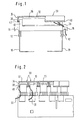
- Fig. 1 In the arrangement shown in Fig. 1 is the Guard 30 according to the invention on a so-called SID (Screw Insulation Penetration) ledge 10 attached.
- SID Small Insulation Penetration
- the SID bar 10 is over in a known manner Locking devices 12 on a trough-like support 18th attached, which in the case shown from two, im Cross section consists of L-shaped legs.
- Locking devices 12 on a trough-like support 18th attached which in the case shown from two, im Cross section consists of L-shaped legs.
- cable guides 16 are several cables 20 to that in the drawing above Area led to the bar 10 in which the (not shown) contacts the terminal block 10 are located.
- the protective cover 30 is substantially as a hollow, formed on a side surface open cuboid and has an upper lid portion 32 and four lateral Wall sections 34.
- the lid portion 32 and the side wall portions 34 is a cavity or a Recess 36 defined in the attached state of the Protective cover 30 of the upper, in particular the contact area of the Bar 10 is included.
- the inventive Protective hood 30 at its edge region 38 with a circumferential Provided sealing element 40.
- the side wall portions 34 designed so that their free Edges 38, which form the edge of the recess 36 in which the Strip 10 is received, essentially in one plane lie. This is especially true in the right section of Fig. 1 based on the largely horizontal orientation of To recognize sealing element 40.
- the surrounding the entire edge of the protective cover 30 trained sealing element 40 is located to seal against dust largely sealed to the module to be protected, in the Case shown, the terminal block 10, at.
- the sealing engagement of the sealing element 40 on the SID strip 10 visible.
- cables 20 on the front side formed Cable guides 16 to the contacts of the terminal block 10th guided.
- cables 20 In the right-hand area of Fig. 1 are two such Cable 20 indicated.
- These cables usually run, such as shown from the contacts on the long sides of the bar 10th to the end-side cable guides 16, or they run from the contacts across the long sides of the strip 10 to the Area below the terminal block 10 in the trough-like Carrier 18.
- the cables 20 extend from the sealed Cavity 36 of the hood 30 out.
- the protective hood 30 according to the invention is designed that in the places where cable 20 from the Protective cover 30 are led out, for a reliable Sealing is ensured.
- the elastic lies Sealing member 40 sealingly connected to the cables 20, to the Long sides of the terminal strips 10 are guided.
- the largely U-shaped cross-section of the individual protective hoods 30 with an upper lid portion 32 and lateral Wall sections 34 can be seen.
- the visible in Fig. 2 Wall sections 34 are the longitudinal wall sections of Protective hood 30, which is substantially parallel to the Longitudinal extension of the terminal block 10 to be protected run.
- the elastic in cross section Seal member 40 is the elastic in cross section Seal member 40 to recognize that around the entire edge is formed circumferentially and for sealing against dust abuts the surfaces of the module 10.
- Fig. 2 in cross-section, penetrate the Cable 20, the sealing element 40 on the longitudinal sides of Terminal block 10, so that in those places to which cable from the interior 36 of the protective cover 30th be led out, the sealing element slightly deformed.
- the sealing element is located both on the surfaces of the Modules as well as on the cables 20, so that no dust and no aggressive ambient air can penetrate.
- the shown and sealing element 40 described may be e.g. in form of a Be formed sealing lip and the protective hood 30 both glued, positively plugged or in 2K injection molding be introduced.
- the edge 38 of the protective hood 30 with a be provided with appropriate contour or it can from this detachable sections have been removed so that cables can be led through the outbreaks, and one extensive sealing against the ingress of dust interaction of a contour or edges of outbreaks achieved with the cables 20 and the surfaces of the module 10 becomes.
- the protective hood 30 according to the invention not only provides for effective protection against dust, but also against Other unfavorable environmental influences, such as humidity and airborne aggressive substances, e.g. Salt.
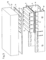
- Fig. 3 is another embodiment of the invention Hood shown, in turn, the cover and sealing of several modules 10 is used.
- Hood 50 which formed in the case shown in two pieces is and from a box-like body 52 and a Seal member 54 is made.
- the body 52 attached to his (not shown) underside is open, comprises in essentially the upper areas of all to be protected Module 10 and covers the contact areas of the modules 10 of above and from the sides against the ingress of dust and largely against the ingress of moist air.
- the seal from below is used in the shown Embodiment of the hood 50, the sealing element 54, in the form a frame with a plurality of recesses 56 is designed.
- the Recesses 56 are to the shape and size of the protected Modules 10 adapted so that the peripheral edges of the Recesses 56 largely sealed in the attached state abut the surfaces of the modules 10. Alternatively you can those edges of the recesses 56 that are in the attached state of the modules 10 and the trough-like Carrier 18 are located on the undersides of the modules 10, not be completely sealed to the discharge of Condensation that occurs in the hood or on the modules Temperature fluctuations deposited, to allow.
- the hood 50 shown is the sealing frame 54 in the Edge of the hood body 52 mounted such that between the Edge of the body 52 and the outer edge of the Seal member 54 at least for the most part no air or Dust is more possible. This can be done at the edge of the Body 52 e.g. two circumferential short groin sections be formed between the sealing element 54th is fitted.
- openings or channels may be provided to the Allow condensation to escape.
- the complete hood 50 from above (in Fig. 3 shown orientation) or from the front (in a final mounting state in the distribution box) attached.
- the sealing frame 54th on the modules and subsequently the Hood body 52 mecanicstecken on the sealing frame 54 and for a seal between the edge of the hood body 52 and the outer edge of the sealing member 54 to provide.
- the hood body 52 of the Modules 10 decrease, and the sealing member 54 to the Leave modules 10. This ensures that the Seal between the edges of the recesses 56 of the Seal member 54 and the surfaces of the modules 10 not gets destroyed.
- the hood body 52 is plugged back and sealed with the outer edge of the sealing frame 54 is connected.
- the edges of the Recesses 56 of the sealing element 54 sealingly, optionally moisture permeable to the undersides of the modules, so that also from the area below the modules 10 between the trough-like supports 18 over the between the modules 10th Column no access of dust to the Contact areas of the modules 10 is more possible.
- the body 52 provides the sealing member 54 dustproof, for a cover of the modules 10 against dust ingress and air circulation to the Contact areas of the modules 10.
- the Sealing element 54 preferably formed elastically, so that the Edges of the recesses 56, which in terms of their size the modules to be protected 10 are designed adapted, itself when resting on the surfaces of the modules 10 a little deform and reliably abut the modules 10. there the deformation can also adjust such that any cables attached to the surfaces of the module 10 lying adjacent to the contacts of the module 10, for a corresponding deformation of the edges of the recesses 56th which are now in sections on the surfaces of the Module 10 and sections of inserted cables issue. Due to the elastic design of the Seal member 54 may be the edges of the recesses 56 adapt to imported cable so that in those areas where cables over the surfaces of the Module 10 are introduced, a reliable seal he follows.
- a hood 50 is in particular therefore advantageous because as a hood body 52 in principle known hoods for modules of telecommunications technology can be used.
- a Hood body 52 advantageously with a Seal member 54 connected to the first time a complete To achieve sealing against dust and environmental influences.
- the hood 50 according to the invention is designed so that Components such as e.g. Isolating plug and Overvoltage protection magazines that are on the modules 10 are plugged, can continue to be used because they inside the hood 50 and its body 52 still Find a place.
Landscapes
- Engineering & Computer Science (AREA)
- Computer Networks & Wireless Communication (AREA)
- Casings For Electric Apparatus (AREA)
- Connector Housings Or Holding Contact Members (AREA)
- Insertion, Bundling And Securing Of Wires For Electric Apparatuses (AREA)
- Exchange Systems With Centralized Control (AREA)
Claims (19)
- Capotpour modules, notamment des barrettes de déconnexion ou de connexion, dans la technique des télécommunications, lesquels présentent plusieurs contacts disposés dans au moins une rangée,pour empêcher la circulation de l'air dans les zones exposées à un danger, notamment dans les zones comprenant les contacts, et pour protéger les contacts contre la poussière et/ou l'humidité,le capot (30, 52) pouvant être emboíté sur au moins un module (10) et, en situation emboítée, entourant au moins la zone du module qui comprend les contacts, etun élément d'étanchéité (40, 54) étant associé au capot (30, 52),l'élément d'étanchéité (40, 54), dans ses zones intérieures, reposant contre le module (10) ou les modules (10) et/ou contre les câbles (20) qui mènent vers les contacts du module (10) ou des modules (10) de manière largement étanche.
- Capot selon la revendication 1, caractérisé en ce que l'élément d'étanchéité (40, 54) avec le capot (30, 52) est constitué de deux parties et que le bord (38) du capot (30, 52) repose contre le bord extérieur de l'élément d'étanchéité (40, 54) de manière largement étanche.
- Capot selon la revendication 1 ou 2, caractérisé en ce que dans l'élément d'étanchéité (40, 54) est façonné au moins un creux (56) de telle sorte que les bords du ou des creux (56) reposent contre le module (10) ou les modules (10) et/ou contre les câbles (20) qui mènent vers les contacts du module (10) ou des modules (10) de manière largement étanche.
- Capot selon la revendication 2 ou 3, caractérisé en ce que l'élément d'étanchéité (54) est adapté dans le bord du capot (52).
- Capot selon au moins l'une des revendications précédentes, caractérisé en ce que tous les bords qui reposent contre le module (10) ou les modules (10) reposent de manière à réaliser une étanchéité complète, notamment une étanchéité à la poussière.
- Capot selon au moins l'une des revendications 1 à 4, caractérisé en ce qu'au moins sur un module (10) au moins une portion du bord est disposée sur le module (10) de manière perméable à l'air et notamment à l'humidité.
- Capot selon la revendication 6, caractérisé en ce que la portion de bord perméable, dans une position de montage du module (10), se trouve sur le dessous de celui-ci.
- Capot selon au moins l'une des revendications précédentes, caractérisé en ce que celui-ci présente au moins un creux longitudinal (36) dans lequel, en position montée, viennent se loger le module (10) à protéger et des composants montés sur le module, comme par exemple une cartouche de surtension et une fiche de sectionnement.
- Capot selon au moins l'une des revendications précédentes, caractérisé en ce que le bord (38) du capot (30) s'étend pour l'essentiel dans un plan.
- Capot selon au moins l'une des revendications précédentes, caractérisé en ce que celui-ci présente un élément d'étanchéité (40) élastique, notamment dans les zones qui, en position montée, reposent au moins partiellement contre le module (10) à protéger.
- Capot selon la revendication 10, caractérisé en ce que l'élément d'étanchéité (40) est réalisé sous la forme d'une lèvre d'étanchéité ou d'un balais d'étanchéité.
- Capot selon la revendication 10 ou 11, caractérisé en ce que l'élément d'étanchéité (40) est configuré pour l'essentiel de manière à faire le tour de tout lé bord (38) du capot (30).
- Capot selon au moins l'une des revendications précédentes, caractérisé en ce que celui-ci présente des éléments extractibles au moins dans les zones qui, en position montée, sont au moins partiellement en contact avec le module (10) à protéger et reposent contre le module (10).
- Capot selon la revendication 13, caractérisé en ce que les éléments extractibles sont, au niveau de leur taille, adaptés aux câbles (20) qui mènent vers la zone de contact du module (10) à protéger.
- Capot selon au moins l'une des revendications précédentes, caractérisé en ce que le bord (38) du capot (30) présente un contour qui est, par portions, configuré pour un arrangement reposant contre les surfaces du module (10) et, par portions, permet le passage de câbles (20) entre le bord (38) du capot (30) et le module (10).
- Capot selon au moins l'une des revendications précédentes, caractérisé en ce qu'une structure de type labyrinthe en section transversale est formée dans les zones du capot et/ou de l'élément d'étanchéité qui reposent contre la surface du module.
- Capot selon au moins l'une des revendications précédentes, caractérisé en ce qu'il est réalisé transparent.
- Capot selon au moins l'une des revendications précédentes, caractérisé en ce qu'il est réalisé sur un composant, par exemple une cartouche de surtension, qui peut être emboíté sur un module (10).
- Dispositif de protection pour plusieurs modules de la technique des télécommunications comprenant au moins un capot selon au moins l'une des revendications 1 à 17.
Applications Claiming Priority (2)
| Application Number | Priority Date | Filing Date | Title |
|---|---|---|---|
| DE29607356U | 1996-04-23 | ||
| DE29607356U DE29607356U1 (de) | 1996-04-23 | 1996-04-23 | Schutzhaube für Module der Telekommunikationstechnik |
Publications (3)
| Publication Number | Publication Date |
|---|---|
| EP0804043A2 EP0804043A2 (fr) | 1997-10-29 |
| EP0804043A3 EP0804043A3 (fr) | 2000-03-08 |
| EP0804043B1 true EP0804043B1 (fr) | 2005-07-20 |
Family
ID=8022997
Family Applications (1)
| Application Number | Title | Priority Date | Filing Date |
|---|---|---|---|
| EP96119547A Expired - Lifetime EP0804043B1 (fr) | 1996-04-23 | 1996-12-05 | Capot de protection pour modules dans la technique des télécommunications |
Country Status (5)
| Country | Link |
|---|---|
| EP (1) | EP0804043B1 (fr) |
| BR (1) | BR9700821A (fr) |
| DE (2) | DE29607356U1 (fr) |
| PL (1) | PL180904B1 (fr) |
| RU (1) | RU2161383C2 (fr) |
Families Citing this family (2)
| Publication number | Priority date | Publication date | Assignee | Title |
|---|---|---|---|---|
| RU2214699C2 (ru) * | 2001-02-05 | 2003-10-20 | Акционерное общество закрытого типа "Контактор" | Устройство для установки печатных плат |
| JP7159798B2 (ja) * | 2018-11-09 | 2022-10-25 | 株式会社デンソー | 保護カバーおよび車載用装置 |
Citations (2)
| Publication number | Priority date | Publication date | Assignee | Title |
|---|---|---|---|---|
| FR2662030A1 (fr) * | 1990-05-09 | 1991-11-15 | Aguera Michel | Coffret de protection pour appareillages et composants divers. |
| EP0563996A2 (fr) * | 1992-04-03 | 1993-10-06 | The Whitaker Corporation | Module de connexion pour boîtier de connexion de lignes téléphoniques et méthode pour protéger un circuit |
Family Cites Families (7)
| Publication number | Priority date | Publication date | Assignee | Title |
|---|---|---|---|---|
| DE2456802C3 (de) * | 1974-11-30 | 1980-12-11 | Robert Bosch Gmbh, 7000 Stuttgart | Elektronisches Schaltgerät |
| GB2054968B (en) * | 1979-07-10 | 1984-05-16 | Plessey Co Ltd | Cover assemblies for electrical devices |
| US4734061A (en) * | 1986-12-31 | 1988-03-29 | Bell Communications Research, Inc. | Telecommunications terminal block |
| DE8717767U1 (de) * | 1987-12-23 | 1989-12-28 | Christoph Emmerich GmbH & Co KG, 6000 Frankfurt | Telekommunikationsgerät, insbesondere Fernsprech-Nebenstellenanlage |
| SE9001157L (sv) * | 1990-03-29 | 1991-09-16 | Mecman Ab | Elektrisk anslutningsanordning foer pilotventiler i en ventilramp |
| FR2670055B1 (fr) * | 1990-11-30 | 1993-01-15 | Cit Alcatel | Boitier de protection contre les perturbations electromagnetiques, pour dispositif de connexion electrique. |
| DE9420759U1 (de) * | 1994-12-27 | 1995-05-24 | Siemens AG, 80333 München | Kommunikationssystem |
-
1996
- 1996-04-23 DE DE29607356U patent/DE29607356U1/de not_active Expired - Lifetime
- 1996-12-05 EP EP96119547A patent/EP0804043B1/fr not_active Expired - Lifetime
- 1996-12-05 DE DE59611248T patent/DE59611248D1/de not_active Expired - Fee Related
- 1996-12-20 RU RU96124078/09A patent/RU2161383C2/ru not_active IP Right Cessation
- 1996-12-20 PL PL96317630A patent/PL180904B1/pl not_active IP Right Cessation
-
1997
- 1997-01-30 BR BR9700821A patent/BR9700821A/pt active Search and Examination
Patent Citations (2)
| Publication number | Priority date | Publication date | Assignee | Title |
|---|---|---|---|---|
| FR2662030A1 (fr) * | 1990-05-09 | 1991-11-15 | Aguera Michel | Coffret de protection pour appareillages et composants divers. |
| EP0563996A2 (fr) * | 1992-04-03 | 1993-10-06 | The Whitaker Corporation | Module de connexion pour boîtier de connexion de lignes téléphoniques et méthode pour protéger un circuit |
Also Published As
| Publication number | Publication date |
|---|---|
| DE59611248D1 (de) | 2005-08-25 |
| DE29607356U1 (de) | 1997-08-28 |
| BR9700821A (pt) | 1998-07-07 |
| EP0804043A2 (fr) | 1997-10-29 |
| PL180904B1 (pl) | 2001-04-30 |
| PL317630A1 (en) | 1997-10-27 |
| EP0804043A3 (fr) | 2000-03-08 |
| RU2161383C2 (ru) | 2000-12-27 |
Similar Documents
| Publication | Publication Date | Title |
|---|---|---|
| DE3922188C2 (fr) | ||
| EP1383368B1 (fr) | Module pour un appareil électronique, module avec bus de secteur en particulier | |
| DE3717009C2 (fr) | ||
| DE29920935U1 (de) | Überspannungsschutzmagazin | |
| DE4223935C2 (de) | Staub- und wassergeschütztes Elektronikgerät | |
| EP0804043B1 (fr) | Capot de protection pour modules dans la technique des télécommunications | |
| EP0618758B1 (fr) | Unité de commande programmable | |
| DE3146608C2 (de) | Anordnung aus einer Leiterplatte, einer Hybridplatte und einem Halter | |
| EP0162960A1 (fr) | Installation d'aération | |
| EP0340444B1 (fr) | Boîtier pour des équipments électriques ou électroniques | |
| DE3122420C2 (de) | Frontbaustein für Schalt- oder Meldewarten | |
| DE69403026T2 (de) | Teilnehmeranschlussvorrichtung | |
| DE19818477A1 (de) | Überspannungsschutzmagazin für eine Einrichtung der Telekommunikationstechnik | |
| DE19942826C1 (de) | Gehäuse für elektronische Baugruppen | |
| DE69211430T2 (de) | Kabelkopf mit Überlastungssicherung für Fernsprechverteiler | |
| DE9211291U1 (de) | Verteiler für EMV abgeschirmte Schränke | |
| DE29618628U1 (de) | Abgeschirmter Baugruppenträger | |
| DE3413533A1 (de) | Elektrotechnisches geraet, insbesondere fuer die nachrichtentechnik | |
| DE9312842U1 (de) | Elektrische Baugruppe | |
| DE3005617C2 (de) | Überspannungsschutzanordnung für Vermittlungsanlagen | |
| DE3206597C2 (de) | Anschluß-Verteiler | |
| DE3208991C2 (de) | Gehäuse für Leiterkarten | |
| DE3041726C2 (de) | Geräteeinsatz der Vertikalbauweise | |
| DE4230236A1 (de) | Bausatz für Kabelendverschlüsse oder Gehäuse für die elektrische Nachrichtentechnik | |
| DE69207980T2 (de) | Verbindungsanordnung mit verbesserter Zuverlässigkeit für mehradriges Kabel |
Legal Events
| Date | Code | Title | Description |
|---|---|---|---|
| PUAI | Public reference made under article 153(3) epc to a published international application that has entered the european phase |
Free format text: ORIGINAL CODE: 0009012 |
|
| AK | Designated contracting states |
Kind code of ref document: A2 Designated state(s): CH DE ES FR GB GR LI SE |
|
| AX | Request for extension of the european patent |
Free format text: LT PAYMENT 961205 |
|
| PUAL | Search report despatched |
Free format text: ORIGINAL CODE: 0009013 |
|
| AK | Designated contracting states |
Kind code of ref document: A3 Designated state(s): CH DE ES FR GB GR LI SE |
|
| AX | Request for extension of the european patent |
Free format text: LT PAYMENT 19961205 |
|
| RIC1 | Information provided on ipc code assigned before grant |
Free format text: 7H 04Q 1/14 A, 7H 05K 5/02 B, 7H 01R 13/52 B |
|
| 17P | Request for examination filed |
Effective date: 20000425 |
|
| 17Q | First examination report despatched |
Effective date: 20031212 |
|
| GRAP | Despatch of communication of intention to grant a patent |
Free format text: ORIGINAL CODE: EPIDOSNIGR1 |
|
| GRAS | Grant fee paid |
Free format text: ORIGINAL CODE: EPIDOSNIGR3 |
|
| GRAA | (expected) grant |
Free format text: ORIGINAL CODE: 0009210 |
|
| AK | Designated contracting states |
Kind code of ref document: B1 Designated state(s): CH DE ES FR GB GR LI SE |
|
| AX | Request for extension of the european patent |
Extension state: LT |
|
| PG25 | Lapsed in a contracting state [announced via postgrant information from national office to epo] |
Ref country code: GB Free format text: LAPSE BECAUSE OF FAILURE TO SUBMIT A TRANSLATION OF THE DESCRIPTION OR TO PAY THE FEE WITHIN THE PRESCRIBED TIME-LIMIT Effective date: 20050720 |
|
| REG | Reference to a national code |
Ref country code: GB Ref legal event code: FG4D Free format text: NOT ENGLISH |
|
| REG | Reference to a national code |
Ref country code: CH Ref legal event code: EP |
|
| REF | Corresponds to: |
Ref document number: 59611248 Country of ref document: DE Date of ref document: 20050825 Kind code of ref document: P |
|
| PG25 | Lapsed in a contracting state [announced via postgrant information from national office to epo] |
Ref country code: SE Free format text: LAPSE BECAUSE OF FAILURE TO SUBMIT A TRANSLATION OF THE DESCRIPTION OR TO PAY THE FEE WITHIN THE PRESCRIBED TIME-LIMIT Effective date: 20051020 Ref country code: GR Free format text: LAPSE BECAUSE OF FAILURE TO SUBMIT A TRANSLATION OF THE DESCRIPTION OR TO PAY THE FEE WITHIN THE PRESCRIBED TIME-LIMIT Effective date: 20051020 |
|
| PG25 | Lapsed in a contracting state [announced via postgrant information from national office to epo] |
Ref country code: ES Free format text: LAPSE BECAUSE OF FAILURE TO SUBMIT A TRANSLATION OF THE DESCRIPTION OR TO PAY THE FEE WITHIN THE PRESCRIBED TIME-LIMIT Effective date: 20051031 |
|
| LTIE | Lt: invalidation of european patent or patent extension |
Effective date: 20050720 |
|
| PG25 | Lapsed in a contracting state [announced via postgrant information from national office to epo] |
Ref country code: LI Free format text: LAPSE BECAUSE OF NON-PAYMENT OF DUE FEES Effective date: 20051231 Ref country code: CH Free format text: LAPSE BECAUSE OF NON-PAYMENT OF DUE FEES Effective date: 20051231 |
|
| GBV | Gb: ep patent (uk) treated as always having been void in accordance with gb section 77(7)/1977 [no translation filed] |
Effective date: 20050720 |
|
| PLBE | No opposition filed within time limit |
Free format text: ORIGINAL CODE: 0009261 |
|
| STAA | Information on the status of an ep patent application or granted ep patent |
Free format text: STATUS: NO OPPOSITION FILED WITHIN TIME LIMIT |
|
| 26N | No opposition filed |
Effective date: 20060421 |
|
| PG25 | Lapsed in a contracting state [announced via postgrant information from national office to epo] |
Ref country code: DE Free format text: LAPSE BECAUSE OF NON-PAYMENT OF DUE FEES Effective date: 20060701 |
|
| REG | Reference to a national code |
Ref country code: CH Ref legal event code: PL |
|
| EN | Fr: translation not filed | ||
| PG25 | Lapsed in a contracting state [announced via postgrant information from national office to epo] |
Ref country code: FR Free format text: LAPSE BECAUSE OF FAILURE TO SUBMIT A TRANSLATION OF THE DESCRIPTION OR TO PAY THE FEE WITHIN THE PRESCRIBED TIME-LIMIT Effective date: 20060915 |
|
| PG25 | Lapsed in a contracting state [announced via postgrant information from national office to epo] |
Ref country code: FR Free format text: LAPSE BECAUSE OF FAILURE TO SUBMIT A TRANSLATION OF THE DESCRIPTION OR TO PAY THE FEE WITHIN THE PRESCRIBED TIME-LIMIT Effective date: 20050720 |