EP0804043A2 - Capot de protection pour modules dans la technique des télécommunications - Google Patents
Capot de protection pour modules dans la technique des télécommunications Download PDFInfo
- Publication number
- EP0804043A2 EP0804043A2 EP96119547A EP96119547A EP0804043A2 EP 0804043 A2 EP0804043 A2 EP 0804043A2 EP 96119547 A EP96119547 A EP 96119547A EP 96119547 A EP96119547 A EP 96119547A EP 0804043 A2 EP0804043 A2 EP 0804043A2
- Authority
- EP
- European Patent Office
- Prior art keywords
- module
- hood
- modules
- sealing element
- hood according
- Prior art date
- Legal status (The legal status is an assumption and is not a legal conclusion. Google has not performed a legal analysis and makes no representation as to the accuracy of the status listed.)
- Granted
Links
- 230000001681 protective effect Effects 0.000 title claims description 69
- 238000005516 engineering process Methods 0.000 title claims description 11
- 238000007789 sealing Methods 0.000 claims description 78
- 231100001261 hazardous Toxicity 0.000 claims 1
- 230000000284 resting effect Effects 0.000 claims 1
- 230000000717 retained effect Effects 0.000 abstract 1
- 239000000428 dust Substances 0.000 description 32
- 239000000969 carrier Substances 0.000 description 9
- 239000004519 grease Substances 0.000 description 8
- 239000003570 air Substances 0.000 description 6
- 238000004519 manufacturing process Methods 0.000 description 5
- 230000007613 environmental effect Effects 0.000 description 4
- 239000012080 ambient air Substances 0.000 description 3
- 230000008021 deposition Effects 0.000 description 2
- 230000000694 effects Effects 0.000 description 2
- 238000001746 injection moulding Methods 0.000 description 2
- 230000003993 interaction Effects 0.000 description 2
- XLYOFNOQVPJJNP-UHFFFAOYSA-N water Substances O XLYOFNOQVPJJNP-UHFFFAOYSA-N 0.000 description 2
- 230000005540 biological transmission Effects 0.000 description 1
- 230000015572 biosynthetic process Effects 0.000 description 1
- 230000008859 change Effects 0.000 description 1
- 238000009833 condensation Methods 0.000 description 1
- 230000005494 condensation Effects 0.000 description 1
- 239000000356 contaminant Substances 0.000 description 1
- 238000005260 corrosion Methods 0.000 description 1
- 230000007797 corrosion Effects 0.000 description 1
- 238000002474 experimental method Methods 0.000 description 1
- 238000009413 insulation Methods 0.000 description 1
- 230000005923 long-lasting effect Effects 0.000 description 1
- 238000007639 printing Methods 0.000 description 1
- 150000003839 salts Chemical class 0.000 description 1
- 239000000126 substance Substances 0.000 description 1
- 230000032258 transport Effects 0.000 description 1
- 238000009423 ventilation Methods 0.000 description 1
Images

Classifications
-
- H—ELECTRICITY
- H04—ELECTRIC COMMUNICATION TECHNIQUE
- H04Q—SELECTING
- H04Q1/00—Details of selecting apparatus or arrangements
- H04Q1/02—Constructional details
- H04Q1/14—Distribution frames
- H04Q1/142—Terminal blocks for distribution frames
-
- H—ELECTRICITY
- H01—ELECTRIC ELEMENTS
- H01R—ELECTRICALLY-CONDUCTIVE CONNECTIONS; STRUCTURAL ASSOCIATIONS OF A PLURALITY OF MUTUALLY-INSULATED ELECTRICAL CONNECTING ELEMENTS; COUPLING DEVICES; CURRENT COLLECTORS
- H01R13/00—Details of coupling devices of the kinds covered by groups H01R12/70 or H01R24/00 - H01R33/00
- H01R13/46—Bases; Cases
- H01R13/52—Dustproof, splashproof, drip-proof, waterproof, or flameproof cases
- H01R13/5213—Covers
-
- H—ELECTRICITY
- H02—GENERATION; CONVERSION OR DISTRIBUTION OF ELECTRIC POWER
- H02G—INSTALLATION OF ELECTRIC CABLES OR LINES, OR OF COMBINED OPTICAL AND ELECTRIC CABLES OR LINES
- H02G15/00—Cable fittings
- H02G15/08—Cable junctions
- H02G15/10—Cable junctions protected by boxes, e.g. by distribution, connection or junction boxes
- H02G15/117—Cable junctions protected by boxes, e.g. by distribution, connection or junction boxes for multiconductor cables
Definitions
- the invention relates to a protective hood for modules of telecommunications technology.
- the protective hood according to the invention is suitable for isolating or connecting strips which are widely used in telecommunications technology and generally have a plurality of contacts arranged in rows.
- Such isolating or connecting strips are used in so-called distribution devices in which, on the one hand, the cables coming from telecommunications offices or switching devices and, on the other hand, the cables leading to individual households or extensions are terminated. This conclusion takes place in each case on the dividing strips described at the beginning.
- So-called patch cords are routed between individual isolating or connecting strips within the distribution device in order to assign the telecommunications cables leading to individual households or extensions to the individual exchange lines.
- active devices for the transmission systems have been installed increasingly in the described distribution devices. These usually heat up during operation and have to be cooled by convection ventilation in the distributor device. Air is thus introduced into the distributor device and moved and circulated in it in order to cool the active components.
- the dust introduced can, among other things, deposit in the area of the contacts of the isolating and connection strips and in particular deteriorates the insulation values of the connection technology if it absorbs moisture. For this reason, the connection technology installed in the distributor device must be effectively protected against the deposition of dust.
- the terminal strips must always be protected against environmental influences. This is the case if the distribution device described is to be used at a location where there is regularly a high level of humidity or particularly aggressive ambient air. Such conditions are e.g. if the ambient air is very salty.
- open dust protection hoods which are each plugged over several modules. These known hoods are plugged on from the side of the modules on which the contacts are located. These dust covers are usually spaced for ten Modules arranged one above the other are formed and generally have the shape of a rectangular cover with side walls pulled down to the side. With the side walls, such a dust protection hood extends on the end faces of the adjacent modules approximately to the height of the modules, in which the devices of the modules are located, with which they are plugged onto known trough-like carriers and fastened thereon.
- the dust protection hoods described are thus arranged approximately mirror-symmetrically to the trough-like carriers if the plane of the attachment of the modules to the trough-like carriers forms the plane of symmetry.
- Dust caps are also known, each of which loosely rests on individual modules and, in particular together with grease or gel, provides protection for the modules.
- the modules are filled with grease or gel, and this filling is protected by loose caps.
- These protective caps also largely prevent dust from being deposited on the contacts, which are also provided with grease or gel, and from sticking to them.
- Such a protective arrangement with a protective cap and grease or gel is, on the one hand, expensive and, on the other hand, impractical and not very user-friendly since the filled gel in the event of a change in circuits or grease must be removed with difficulty.
- the gel or fat generally tends to settle in the entire interior of a distribution box, so that distribution boxes in which protective caps filled with fat or gel are attached are generally very dirty. These contaminants make working on such distribution boxes a comparatively dirty and tedious affair. Finally, the filled grease or gel, which can flow out of the loose protective caps, may need to be refilled.
- the object of the present invention (the technical problem) is to provide a protective hood which guarantees effective protection, in particular against the deposition of dust, is inexpensive to manufacture and is easy to use.
- the protective hood according to the invention can be plugged onto one or more modules and, when plugged in, comprises at least the area of the module in which the contacts are located. Furthermore, the protective hood is assigned a sealing element.
- the sealing element lies in a largely sealing manner on the module or modules and / or on the cables leading to the contacts of the module in its inner regions.
- the protective hood according to the invention thus ensures reliable sealing due to the surrounding and effective covering of the contact area of the module. This allows dust to enter the contact area of the module and Dust deposits can be avoided in this area.
- the sealing element can be designed as a one-piece component of the protective hood, for example in the form of a sealing edge contour.
- the sealing element is preferably designed as a separate component, on the outer edge of which the edge of the protective hood bears in a largely sealing manner, in order also to provide a seal at the interface between the hood body and the sealing element.
- the edges of the protective hood or the separate sealing element which cooperate for sealing with the surfaces of the module or the cables leading to the module, lie largely sealing against the contact zones, the contacts of the individual module are effectively protected against dust.
- the protective hood can also be used in combination with grease or gel if the application so requires.
- the protective hood Sliding on or attaching the protective hood requires only a small amount of assembly. Furthermore, the protective hood can be secured by a corresponding latching device between the module to be protected and a section of the protective hood, so that particularly long-lasting protection is achieved.
- the sealing element has at least one recess which is designed such that the edges of the recess bear in a largely sealing manner on the module or modules and / or on cables leading to the contacts of the module or modules.
- the shape of the recess is adapted to the shape and size of the module to be protected and, if appropriate, to components plugged onto it.
- the interior of the recess thus encompasses the contact area of the modules, and the edge of the recess provides an effective seal.
- the edge of the protective hood is designed so that it runs essentially in one plane.
- the manufacture of the protective hood according to the invention is particularly simple, and the reliably sealing design of the edge of the protective hood can be made particularly simple.
- the protective hood has a preferably elastic sealing element.
- a sealing element is formed in those areas of the protective hood that at least partially abut the module to be protected in the attached state, so that effective protection is achieved by the interaction of the sealing element with the surfaces of the module or inserted cable.
- a good sealing effect was found in a protective hood according to the invention, which was provided with such a sealing element.
- the sealing element is preferably designed in the form of a sealing lip, which is special due to its elastic structure fits tightly.
- the sealing element can be glued to the protective hood, attached with a positive fit, or introduced using the two-component injection molding process.
- a further preferred embodiment of the protective hood according to the invention has removable sections in the regions which at least partially bear against the module or inserted cables in the attached state.
- the sections can in particular be removed from the edge of the protective hood, so that cables can be inserted through the resulting recesses, and the edge of the recess interacts with the surface of the inserted cable for sealing.
- Extractable sections the size of which is adapted to the size of cables according to a preferred embodiment, are particularly effective for sealing the contact area of the modules that lead to the contact area of the module.
- the protective hood according to the invention can be provided with as many cutouts on the edge of the protective hood as is necessary for the introduction of the required number of cables as part of the attachment to a module by removing individual sections.
- the protective hood can already be designed and constructed such that suitable cutouts for the passage of cables do not first have to be broken out, but are already formed in the contour of the edge of the protective hood.
- the amount of work involved in attaching the protective hood according to the invention can be reduced.
- the production of a protective hood with an edge contour, which is suitable for the passage of cables, is possible with suitable manufacturing processes and corresponding shapes with little effort.
- the protective hood according to the invention is transparent. This means that even with the protective hood attached, the circuitry and printing of the module and the assignment of the individual ones Contacts visible.
- the protective hood according to the invention can be dimensioned accordingly and provided with a correspondingly large cavity or a correspondingly large recess. If the preferred embodiment of a transparent hood is used in this case, the attached components mentioned can also be seen with the hood attached. In this embodiment of the protective hood according to the invention, there are particular advantages for the user, since the wiring and fitting with the usual components always remains recognizable.
- the protective hood according to the invention if it does not represent a separate component, but rather is formed on a fundamentally known or existing component that can be plugged onto a module to be protected. This can minimize the effort required to perform both the function of the component to be attached anyway and the function of the protective hood.
- an overvoltage magazine is preferably provided for the pluggable component on which the protective hood is formed. This requires only little effort, since the housing contour of the overvoltage magazine only has to be supplemented in a simple manner in the lower region by the elastic seal described above or by removable sections to form a sealing contour.
- an overvoltage magazine for a module in particular a connector strip, is presented for telecommunications technology.
- a protective hood which is designed in the manner described above.
- the edge of the individual recess or of the individual hood-like section lies in a sealing manner on the individual module to be protected, so that the contact area of the individual module in each case comprises or is covered and by the sealing contact of the edge area against dust deposits and is protected from environmental influences.
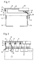
- the protective hood 30 according to the invention is mounted on a so-called SID (screw-insulation-penetration) strip 10.
- the SID bar 10 is plugged in a known manner via latching devices 12 onto a trough-like carrier 18, which in the case shown consists of two legs with an L-shaped cross section.
- a plurality of cables 20 are routed through the cable guides 16 attached to the side of the terminal strip 10 to the area of the strip 10 located at the top in the drawing, in which the contacts (not shown) of the terminal strip 10 are located.
- the protective hood 30 is essentially designed as a hollow cuboid open on one side surface and has an upper cover section 32 and four side wall sections 34.
- a cover or recess 36 is defined by the cover section 32 and the side wall sections 34, in which the upper, in particular the contact area of the strip 10 is received in the attached state of the protective hood 30.
- the protective hood 30 is provided at its edge region 38 with a circumferential sealing element 40.
- the side wall sections 34 are designed such that their free edges 38, which form the edge of the recess 36 in which the strip 10 is received, lie essentially in one plane. This can be seen in particular in the right section of FIG. 1 on the basis of the largely horizontal orientation of the sealing element 40.
- the sealing element 40 which extends around the entire edge of the protective hood 30, is largely sealed against the module to be protected, in the case shown the terminal strip 10, for sealing against dust.
- the sectional view of the left area of FIG. 1 shows the sealing abutment of the sealing element 40 on the SID bar 10.
- a plurality of cables 20 are guided to the contacts of the terminal block 10 via the cable guides 16 formed on the end face.
- Two such cables 20 are indicated in the right-hand area of FIG. 1.
- These cables usually run, as shown, from the contacts over the long sides of the bar 10 to the front cable guides 16, or they run from the contacts over the long sides of the bar 10 to the area below the terminal block 10 in the trough-like carrier 18.
- the protective hood 30 according to the invention is designed so that a reliable seal is also provided at the points at which cables 20 are led out of the protective hood 30.
- the elastic sealing element 40 lies in a sealing manner on the cables 20, which are guided on the longitudinal sides of the terminal strips 10.
- the largely U-shaped cross section of the individual protective hoods 30 with an upper cover section 32 and lateral wall sections 34 can be seen in the sectional view of the left area of FIG. 2.
- the wall sections 34 visible in FIG. 2 are the longitudinal wall sections of the protective hood 30, which run essentially parallel to the longitudinal extent of the terminal strip 10 to be protected.
- At the lower edges 38 of the longitudinal wall sections 34 is the elastic in cross section
- sealing element 40 which is formed all around the entire edge and bears against the surfaces of the module 10 for sealing against dust.
- the cables 20 penetrate the sealing element 40 on the long sides of the terminal strip 10, so that the sealing element is slightly deformed at those points where cables are led out from the interior 36 of the protective hood 30.
- the sealing element bears against both the surfaces of the module and the cables 20, so that no dust and no aggressive ambient air can penetrate.
- the sealing element 40 shown and described can e.g. be designed in the form of a sealing lip and both glued to the protective hood 30, connected in a form-fitting manner or introduced using the two-component injection molding process.
- the edge 38 of the protective hood 30 can be provided with a corresponding contour or parts that can be removed from it can be removed so that cables can be guided through the cutouts, and an extensive seal against the ingress of dust by the interaction of the contour or the edges of the breakouts with the cables 20 and the surfaces of the module 10 is reached.
- the protective hood 30 according to the invention not only provides effective protection against dust, but also against other unfavorable environmental influences, such as atmospheric moisture and aggressive substances contained in the air, such as e.g. Salt.
- FIG. 3 shows another embodiment of the hood according to the invention, which in turn covers and seals serves several modules 10.
- the attachment of the modules 10 to trough-like carriers 18 can be seen in the perspective view of FIG. 3, wherein, as shown, the elongate modules 10 are usually plugged onto the trough-like carriers 18 parallel to one another. Lateral and frontal cable guides 14 formed on the modules 10 are also shown, via which the cables are guided to the contacts located in the upper regions of the modules 10.
- the hood 50 shown is used, which in the case shown is formed in two pieces and consists of a box-like body 52 and a sealing element 54.
- the body 52 which is open on its underside (not shown), essentially comprises the upper regions of all the modules 10 to be protected and covers the contact regions of the modules 10 from above and from the side against the ingress of dust and largely against the ingress from moist air.
- the sealing element 54 which is designed in the form of a frame with a plurality of recesses 56.
- the recesses 56 are adapted to the shape and size of the modules 10 to be protected in such a way that the circumferential edges of the recesses 56 bear in a largely sealing manner on the surfaces of the modules 10 in the attached state.
- those edges of the recesses 56, which are in the attached state of the modules 10 and the trough-like carrier 18 on the undersides of the modules 10 may not be designed to be completely sealed in order to prevent condensation water that is in the hood or on the modules deposits in the event of temperature fluctuations.
- the trough-like carriers 18 shown are arranged vertically in distribution boxes, so that the attached modules 10 extend in a horizontal direction from the trough-like carriers 18. Accordingly, in the attached state, the hood 50 shown is oriented in such a way that its cover surface (located at the top in FIG. 3) extends vertically and covers the entire arrangement of modules 10 and carriers 18, particularly in the forward direction.
- the sealing frame 54 is attached in the edge of the hood body 52 such that at least for the most part no more air or dust can pass between the edge of the body 52 and the outer edge of the sealing element 54.
- two circumferential short strip sections can be formed, between which the sealing element 54 is fitted.
- openings or channels can optionally be provided on the underside of the hood, which allow condensed water to escape.
- the complete hood 50 is fitted from above (orientation shown in FIG. 3) or from the front (in a final attachment state in the distribution box).
- the hood body 52 is reattached and sealingly connected to the outer edge of the sealing frame 54.
- the edges of the recesses 56 of the sealing element 54 lie in a sealing manner, optionally permeable to moisture on the undersides of the modules, so that also from the area below the modules 10 between the trough-like supports 18 via the gaps between the modules 10 dust is no longer accessible to the contact areas of the modules 10.
- the body 52 in which the sealing element 54 is fitted in a dust-tight manner, ensures that the modules 10 are covered against dust and the air circulation to the contact areas of the modules 10.
- the sealing element 54 is preferably designed to be elastic, so that the edges of the recesses 56, which are designed in terms of their size to match the modules 10 to be protected, come into contact with one another deform the surfaces of the modules 10 a little and rest reliably on the modules 10.
- the deformation can also occur in such a way that any cables that are guided on the surfaces of the module 10 to the contacts of the module 10, ensure a corresponding deformation of the edges of the recesses 56, which now rest in sections on the surfaces of the module 10 and in sections on inserted cables. Due to the elastic design of the sealing element 54, the edges of the recesses 56 can adapt to inserted cables in such a way that a reliable seal is also provided in those areas in which cables are inserted over the surfaces of the module 10.
- a hood 50 shown is particularly advantageous because hoods 52 which are known in principle can be used as hood bodies 52 for modules in telecommunications technology.
- a hood body 52 is advantageously connected to a sealing element 54 in order to achieve a complete seal against dust and environmental influences for the first time.
- the hood 50 according to the invention is designed so that components such as e.g. Isolating plugs and surge protection magazines, which are plugged onto the modules 10, can continue to be used because they still find space inside the hood 50 or its body 52.
Landscapes
- Engineering & Computer Science (AREA)
- Computer Networks & Wireless Communication (AREA)
- Casings For Electric Apparatus (AREA)
- Connector Housings Or Holding Contact Members (AREA)
- Insertion, Bundling And Securing Of Wires For Electric Apparatuses (AREA)
- Exchange Systems With Centralized Control (AREA)
Applications Claiming Priority (2)
| Application Number | Priority Date | Filing Date | Title |
|---|---|---|---|
| DE29607356U | 1996-04-23 | ||
| DE29607356U DE29607356U1 (de) | 1996-04-23 | 1996-04-23 | Schutzhaube für Module der Telekommunikationstechnik |
Publications (3)
| Publication Number | Publication Date |
|---|---|
| EP0804043A2 true EP0804043A2 (fr) | 1997-10-29 |
| EP0804043A3 EP0804043A3 (fr) | 2000-03-08 |
| EP0804043B1 EP0804043B1 (fr) | 2005-07-20 |
Family
ID=8022997
Family Applications (1)
| Application Number | Title | Priority Date | Filing Date |
|---|---|---|---|
| EP96119547A Expired - Lifetime EP0804043B1 (fr) | 1996-04-23 | 1996-12-05 | Capot de protection pour modules dans la technique des télécommunications |
Country Status (5)
| Country | Link |
|---|---|
| EP (1) | EP0804043B1 (fr) |
| BR (1) | BR9700821A (fr) |
| DE (2) | DE29607356U1 (fr) |
| PL (1) | PL180904B1 (fr) |
| RU (1) | RU2161383C2 (fr) |
Families Citing this family (2)
| Publication number | Priority date | Publication date | Assignee | Title |
|---|---|---|---|---|
| RU2214699C2 (ru) * | 2001-02-05 | 2003-10-20 | Акционерное общество закрытого типа "Контактор" | Устройство для установки печатных плат |
| JP7159798B2 (ja) * | 2018-11-09 | 2022-10-25 | 株式会社デンソー | 保護カバーおよび車載用装置 |
Family Cites Families (9)
| Publication number | Priority date | Publication date | Assignee | Title |
|---|---|---|---|---|
| DE2456802C3 (de) * | 1974-11-30 | 1980-12-11 | Robert Bosch Gmbh, 7000 Stuttgart | Elektronisches Schaltgerät |
| GB2054968B (en) * | 1979-07-10 | 1984-05-16 | Plessey Co Ltd | Cover assemblies for electrical devices |
| US4734061A (en) * | 1986-12-31 | 1988-03-29 | Bell Communications Research, Inc. | Telecommunications terminal block |
| DE8717767U1 (de) * | 1987-12-23 | 1989-12-28 | Christoph Emmerich GmbH & Co KG, 6000 Frankfurt | Telekommunikationsgerät, insbesondere Fernsprech-Nebenstellenanlage |
| SE9001157L (sv) * | 1990-03-29 | 1991-09-16 | Mecman Ab | Elektrisk anslutningsanordning foer pilotventiler i en ventilramp |
| FR2662030B1 (fr) * | 1990-05-09 | 1992-09-04 | Aguera Michel | Coffret de protection pour appareillages et composants divers. |
| FR2670055B1 (fr) * | 1990-11-30 | 1993-01-15 | Cit Alcatel | Boitier de protection contre les perturbations electromagnetiques, pour dispositif de connexion electrique. |
| US5296646A (en) * | 1992-04-03 | 1994-03-22 | The Whitaker Corporation | Protector module for telephone line junction box |
| DE9420759U1 (de) * | 1994-12-27 | 1995-05-24 | Siemens AG, 80333 München | Kommunikationssystem |
-
1996
- 1996-04-23 DE DE29607356U patent/DE29607356U1/de not_active Expired - Lifetime
- 1996-12-05 EP EP96119547A patent/EP0804043B1/fr not_active Expired - Lifetime
- 1996-12-05 DE DE59611248T patent/DE59611248D1/de not_active Expired - Fee Related
- 1996-12-20 RU RU96124078/09A patent/RU2161383C2/ru not_active IP Right Cessation
- 1996-12-20 PL PL96317630A patent/PL180904B1/pl not_active IP Right Cessation
-
1997
- 1997-01-30 BR BR9700821A patent/BR9700821A/pt active Search and Examination
Non-Patent Citations (1)
| Title |
|---|
| None |
Also Published As
| Publication number | Publication date |
|---|---|
| DE59611248D1 (de) | 2005-08-25 |
| DE29607356U1 (de) | 1997-08-28 |
| BR9700821A (pt) | 1998-07-07 |
| EP0804043B1 (fr) | 2005-07-20 |
| PL180904B1 (pl) | 2001-04-30 |
| PL317630A1 (en) | 1997-10-27 |
| EP0804043A3 (fr) | 2000-03-08 |
| RU2161383C2 (ru) | 2000-12-27 |
Similar Documents
| Publication | Publication Date | Title |
|---|---|---|
| DE4344659C1 (de) | Filterlüfter zum Anbau an spritzwassergeschützte Gehäuse oder Schaltschränke | |
| DE20211002U1 (de) | Modul für ein elektrisches Gerät, insbesondere Feldbusmodul | |
| WO2001029931A1 (fr) | Connecteur pourvu d'un blindage | |
| DE1861066U (de) | Dreidimensional aufgebaute schaltungsanordnung mit blockfoermigen, in ein rahmengestell einschiebbaren schaltungsgruppen. | |
| DE69318331T2 (de) | Fernsprechverteilerelement, insbesondere Anschlussklemmleiste | |
| DE3830133A1 (de) | Belueftete, spritzwassergeschuetzte gehaeusebaugruppe fuer elektrische bauteile | |
| DE4322535A1 (de) | Elektrische Klemmen mit steckbaren Querbrückern | |
| DE4223935C2 (de) | Staub- und wassergeschütztes Elektronikgerät | |
| DE102008062250A1 (de) | Installationsschaltgerät mit einem Isollierstoffgehäuse | |
| DE10061940A1 (de) | Kupplungsplatte für Stromschienenadapter | |
| EP0618758B1 (fr) | Unité de commande programmable | |
| EP0804043A2 (fr) | Capot de protection pour modules dans la technique des télécommunications | |
| DE4447731C2 (de) | Steckverbinder | |
| EP0116162A2 (fr) | Dispositif pour le montage enfichable d'un porteur de circuit électrique sur un appareil électrique ou similaire et procédé pour le fabriquer | |
| EP0749180B1 (fr) | Boítier de connecteur à fiche | |
| EP0162960A1 (fr) | Installation d'aération | |
| DE3146608C2 (de) | Anordnung aus einer Leiterplatte, einer Hybridplatte und einem Halter | |
| DE4301602C1 (de) | Elektrisches Steckverbindungsteil | |
| DE3149387C2 (fr) | ||
| CH663292A5 (de) | Schaltschrank. | |
| EP0498402B1 (fr) | Couverture pour une prise électrique ou une combinaison de prises électriques | |
| DE29618628U1 (de) | Abgeschirmter Baugruppenträger | |
| DE9403212U1 (de) | Gehäuse zur Aufnahme von bestückten Leiterplatten | |
| DE4439673A1 (de) | Leiterplatten-Steckverbinder | |
| DE10324411B4 (de) | Elektronisches Gerät |
Legal Events
| Date | Code | Title | Description |
|---|---|---|---|
| PUAI | Public reference made under article 153(3) epc to a published international application that has entered the european phase |
Free format text: ORIGINAL CODE: 0009012 |
|
| AK | Designated contracting states |
Kind code of ref document: A2 Designated state(s): CH DE ES FR GB GR LI SE |
|
| AX | Request for extension of the european patent |
Free format text: LT PAYMENT 961205 |
|
| PUAL | Search report despatched |
Free format text: ORIGINAL CODE: 0009013 |
|
| AK | Designated contracting states |
Kind code of ref document: A3 Designated state(s): CH DE ES FR GB GR LI SE |
|
| AX | Request for extension of the european patent |
Free format text: LT PAYMENT 19961205 |
|
| RIC1 | Information provided on ipc code assigned before grant |
Free format text: 7H 04Q 1/14 A, 7H 05K 5/02 B, 7H 01R 13/52 B |
|
| 17P | Request for examination filed |
Effective date: 20000425 |
|
| 17Q | First examination report despatched |
Effective date: 20031212 |
|
| GRAP | Despatch of communication of intention to grant a patent |
Free format text: ORIGINAL CODE: EPIDOSNIGR1 |
|
| GRAS | Grant fee paid |
Free format text: ORIGINAL CODE: EPIDOSNIGR3 |
|
| GRAA | (expected) grant |
Free format text: ORIGINAL CODE: 0009210 |
|
| AK | Designated contracting states |
Kind code of ref document: B1 Designated state(s): CH DE ES FR GB GR LI SE |
|
| AX | Request for extension of the european patent |
Extension state: LT |
|
| PG25 | Lapsed in a contracting state [announced via postgrant information from national office to epo] |
Ref country code: GB Free format text: LAPSE BECAUSE OF FAILURE TO SUBMIT A TRANSLATION OF THE DESCRIPTION OR TO PAY THE FEE WITHIN THE PRESCRIBED TIME-LIMIT Effective date: 20050720 |
|
| REG | Reference to a national code |
Ref country code: GB Ref legal event code: FG4D Free format text: NOT ENGLISH |
|
| REG | Reference to a national code |
Ref country code: CH Ref legal event code: EP |
|
| REF | Corresponds to: |
Ref document number: 59611248 Country of ref document: DE Date of ref document: 20050825 Kind code of ref document: P |
|
| PG25 | Lapsed in a contracting state [announced via postgrant information from national office to epo] |
Ref country code: SE Free format text: LAPSE BECAUSE OF FAILURE TO SUBMIT A TRANSLATION OF THE DESCRIPTION OR TO PAY THE FEE WITHIN THE PRESCRIBED TIME-LIMIT Effective date: 20051020 Ref country code: GR Free format text: LAPSE BECAUSE OF FAILURE TO SUBMIT A TRANSLATION OF THE DESCRIPTION OR TO PAY THE FEE WITHIN THE PRESCRIBED TIME-LIMIT Effective date: 20051020 |
|
| PG25 | Lapsed in a contracting state [announced via postgrant information from national office to epo] |
Ref country code: ES Free format text: LAPSE BECAUSE OF FAILURE TO SUBMIT A TRANSLATION OF THE DESCRIPTION OR TO PAY THE FEE WITHIN THE PRESCRIBED TIME-LIMIT Effective date: 20051031 |
|
| LTIE | Lt: invalidation of european patent or patent extension |
Effective date: 20050720 |
|
| PG25 | Lapsed in a contracting state [announced via postgrant information from national office to epo] |
Ref country code: LI Free format text: LAPSE BECAUSE OF NON-PAYMENT OF DUE FEES Effective date: 20051231 Ref country code: CH Free format text: LAPSE BECAUSE OF NON-PAYMENT OF DUE FEES Effective date: 20051231 |
|
| GBV | Gb: ep patent (uk) treated as always having been void in accordance with gb section 77(7)/1977 [no translation filed] |
Effective date: 20050720 |
|
| PLBE | No opposition filed within time limit |
Free format text: ORIGINAL CODE: 0009261 |
|
| STAA | Information on the status of an ep patent application or granted ep patent |
Free format text: STATUS: NO OPPOSITION FILED WITHIN TIME LIMIT |
|
| 26N | No opposition filed |
Effective date: 20060421 |
|
| PG25 | Lapsed in a contracting state [announced via postgrant information from national office to epo] |
Ref country code: DE Free format text: LAPSE BECAUSE OF NON-PAYMENT OF DUE FEES Effective date: 20060701 |
|
| REG | Reference to a national code |
Ref country code: CH Ref legal event code: PL |
|
| EN | Fr: translation not filed | ||
| PG25 | Lapsed in a contracting state [announced via postgrant information from national office to epo] |
Ref country code: FR Free format text: LAPSE BECAUSE OF FAILURE TO SUBMIT A TRANSLATION OF THE DESCRIPTION OR TO PAY THE FEE WITHIN THE PRESCRIBED TIME-LIMIT Effective date: 20060915 |
|
| PG25 | Lapsed in a contracting state [announced via postgrant information from national office to epo] |
Ref country code: FR Free format text: LAPSE BECAUSE OF FAILURE TO SUBMIT A TRANSLATION OF THE DESCRIPTION OR TO PAY THE FEE WITHIN THE PRESCRIBED TIME-LIMIT Effective date: 20050720 |