EP0804043A2 - Protective cover for modules in telecommunication technology - Google Patents
Protective cover for modules in telecommunication technology Download PDFInfo
- Publication number
- EP0804043A2 EP0804043A2 EP96119547A EP96119547A EP0804043A2 EP 0804043 A2 EP0804043 A2 EP 0804043A2 EP 96119547 A EP96119547 A EP 96119547A EP 96119547 A EP96119547 A EP 96119547A EP 0804043 A2 EP0804043 A2 EP 0804043A2
- Authority
- EP
- European Patent Office
- Prior art keywords
- module
- hood
- modules
- sealing element
- hood according
- Prior art date
- Legal status (The legal status is an assumption and is not a legal conclusion. Google has not performed a legal analysis and makes no representation as to the accuracy of the status listed.)
- Granted
Links
- 230000001681 protective effect Effects 0.000 title claims description 69
- 238000005516 engineering process Methods 0.000 title claims description 11
- 238000007789 sealing Methods 0.000 claims description 78
- 231100001261 hazardous Toxicity 0.000 claims 1
- 230000000284 resting effect Effects 0.000 claims 1
- 230000000717 retained effect Effects 0.000 abstract 1
- 239000000428 dust Substances 0.000 description 32
- 239000000969 carrier Substances 0.000 description 9
- 239000004519 grease Substances 0.000 description 8
- 239000003570 air Substances 0.000 description 6
- 238000004519 manufacturing process Methods 0.000 description 5
- 230000007613 environmental effect Effects 0.000 description 4
- 239000012080 ambient air Substances 0.000 description 3
- 230000008021 deposition Effects 0.000 description 2
- 230000000694 effects Effects 0.000 description 2
- 238000001746 injection moulding Methods 0.000 description 2
- 230000003993 interaction Effects 0.000 description 2
- XLYOFNOQVPJJNP-UHFFFAOYSA-N water Substances O XLYOFNOQVPJJNP-UHFFFAOYSA-N 0.000 description 2
- 230000005540 biological transmission Effects 0.000 description 1
- 230000015572 biosynthetic process Effects 0.000 description 1
- 230000008859 change Effects 0.000 description 1
- 238000009833 condensation Methods 0.000 description 1
- 230000005494 condensation Effects 0.000 description 1
- 239000000356 contaminant Substances 0.000 description 1
- 238000005260 corrosion Methods 0.000 description 1
- 230000007797 corrosion Effects 0.000 description 1
- 238000002474 experimental method Methods 0.000 description 1
- 238000009413 insulation Methods 0.000 description 1
- 230000005923 long-lasting effect Effects 0.000 description 1
- 238000007639 printing Methods 0.000 description 1
- 150000003839 salts Chemical class 0.000 description 1
- 239000000126 substance Substances 0.000 description 1
- 230000032258 transport Effects 0.000 description 1
- 238000009423 ventilation Methods 0.000 description 1
Images

Classifications
-
- H—ELECTRICITY
- H04—ELECTRIC COMMUNICATION TECHNIQUE
- H04Q—SELECTING
- H04Q1/00—Details of selecting apparatus or arrangements
- H04Q1/02—Constructional details
- H04Q1/14—Distribution frames
- H04Q1/142—Terminal blocks for distribution frames
-
- H—ELECTRICITY
- H01—ELECTRIC ELEMENTS
- H01R—ELECTRICALLY-CONDUCTIVE CONNECTIONS; STRUCTURAL ASSOCIATIONS OF A PLURALITY OF MUTUALLY-INSULATED ELECTRICAL CONNECTING ELEMENTS; COUPLING DEVICES; CURRENT COLLECTORS
- H01R13/00—Details of coupling devices of the kinds covered by groups H01R12/70 or H01R24/00 - H01R33/00
- H01R13/46—Bases; Cases
- H01R13/52—Dustproof, splashproof, drip-proof, waterproof, or flameproof cases
- H01R13/5213—Covers
-
- H—ELECTRICITY
- H02—GENERATION; CONVERSION OR DISTRIBUTION OF ELECTRIC POWER
- H02G—INSTALLATION OF ELECTRIC CABLES OR LINES, OR OF COMBINED OPTICAL AND ELECTRIC CABLES OR LINES
- H02G15/00—Cable fittings
- H02G15/08—Cable junctions
- H02G15/10—Cable junctions protected by boxes, e.g. by distribution, connection or junction boxes
- H02G15/117—Cable junctions protected by boxes, e.g. by distribution, connection or junction boxes for multiconductor cables
Definitions
- the invention relates to a protective hood for modules of telecommunications technology.
- the protective hood according to the invention is suitable for isolating or connecting strips which are widely used in telecommunications technology and generally have a plurality of contacts arranged in rows.
- Such isolating or connecting strips are used in so-called distribution devices in which, on the one hand, the cables coming from telecommunications offices or switching devices and, on the other hand, the cables leading to individual households or extensions are terminated. This conclusion takes place in each case on the dividing strips described at the beginning.
- So-called patch cords are routed between individual isolating or connecting strips within the distribution device in order to assign the telecommunications cables leading to individual households or extensions to the individual exchange lines.
- active devices for the transmission systems have been installed increasingly in the described distribution devices. These usually heat up during operation and have to be cooled by convection ventilation in the distributor device. Air is thus introduced into the distributor device and moved and circulated in it in order to cool the active components.
- the dust introduced can, among other things, deposit in the area of the contacts of the isolating and connection strips and in particular deteriorates the insulation values of the connection technology if it absorbs moisture. For this reason, the connection technology installed in the distributor device must be effectively protected against the deposition of dust.
- the terminal strips must always be protected against environmental influences. This is the case if the distribution device described is to be used at a location where there is regularly a high level of humidity or particularly aggressive ambient air. Such conditions are e.g. if the ambient air is very salty.
- open dust protection hoods which are each plugged over several modules. These known hoods are plugged on from the side of the modules on which the contacts are located. These dust covers are usually spaced for ten Modules arranged one above the other are formed and generally have the shape of a rectangular cover with side walls pulled down to the side. With the side walls, such a dust protection hood extends on the end faces of the adjacent modules approximately to the height of the modules, in which the devices of the modules are located, with which they are plugged onto known trough-like carriers and fastened thereon.
- the dust protection hoods described are thus arranged approximately mirror-symmetrically to the trough-like carriers if the plane of the attachment of the modules to the trough-like carriers forms the plane of symmetry.
- Dust caps are also known, each of which loosely rests on individual modules and, in particular together with grease or gel, provides protection for the modules.
- the modules are filled with grease or gel, and this filling is protected by loose caps.
- These protective caps also largely prevent dust from being deposited on the contacts, which are also provided with grease or gel, and from sticking to them.
- Such a protective arrangement with a protective cap and grease or gel is, on the one hand, expensive and, on the other hand, impractical and not very user-friendly since the filled gel in the event of a change in circuits or grease must be removed with difficulty.
- the gel or fat generally tends to settle in the entire interior of a distribution box, so that distribution boxes in which protective caps filled with fat or gel are attached are generally very dirty. These contaminants make working on such distribution boxes a comparatively dirty and tedious affair. Finally, the filled grease or gel, which can flow out of the loose protective caps, may need to be refilled.
- the object of the present invention (the technical problem) is to provide a protective hood which guarantees effective protection, in particular against the deposition of dust, is inexpensive to manufacture and is easy to use.
- the protective hood according to the invention can be plugged onto one or more modules and, when plugged in, comprises at least the area of the module in which the contacts are located. Furthermore, the protective hood is assigned a sealing element.
- the sealing element lies in a largely sealing manner on the module or modules and / or on the cables leading to the contacts of the module in its inner regions.
- the protective hood according to the invention thus ensures reliable sealing due to the surrounding and effective covering of the contact area of the module. This allows dust to enter the contact area of the module and Dust deposits can be avoided in this area.
- the sealing element can be designed as a one-piece component of the protective hood, for example in the form of a sealing edge contour.
- the sealing element is preferably designed as a separate component, on the outer edge of which the edge of the protective hood bears in a largely sealing manner, in order also to provide a seal at the interface between the hood body and the sealing element.
- the edges of the protective hood or the separate sealing element which cooperate for sealing with the surfaces of the module or the cables leading to the module, lie largely sealing against the contact zones, the contacts of the individual module are effectively protected against dust.
- the protective hood can also be used in combination with grease or gel if the application so requires.
- the protective hood Sliding on or attaching the protective hood requires only a small amount of assembly. Furthermore, the protective hood can be secured by a corresponding latching device between the module to be protected and a section of the protective hood, so that particularly long-lasting protection is achieved.
- the sealing element has at least one recess which is designed such that the edges of the recess bear in a largely sealing manner on the module or modules and / or on cables leading to the contacts of the module or modules.
- the shape of the recess is adapted to the shape and size of the module to be protected and, if appropriate, to components plugged onto it.
- the interior of the recess thus encompasses the contact area of the modules, and the edge of the recess provides an effective seal.
- the edge of the protective hood is designed so that it runs essentially in one plane.
- the manufacture of the protective hood according to the invention is particularly simple, and the reliably sealing design of the edge of the protective hood can be made particularly simple.
- the protective hood has a preferably elastic sealing element.
- a sealing element is formed in those areas of the protective hood that at least partially abut the module to be protected in the attached state, so that effective protection is achieved by the interaction of the sealing element with the surfaces of the module or inserted cable.
- a good sealing effect was found in a protective hood according to the invention, which was provided with such a sealing element.
- the sealing element is preferably designed in the form of a sealing lip, which is special due to its elastic structure fits tightly.
- the sealing element can be glued to the protective hood, attached with a positive fit, or introduced using the two-component injection molding process.
- a further preferred embodiment of the protective hood according to the invention has removable sections in the regions which at least partially bear against the module or inserted cables in the attached state.
- the sections can in particular be removed from the edge of the protective hood, so that cables can be inserted through the resulting recesses, and the edge of the recess interacts with the surface of the inserted cable for sealing.
- Extractable sections the size of which is adapted to the size of cables according to a preferred embodiment, are particularly effective for sealing the contact area of the modules that lead to the contact area of the module.
- the protective hood according to the invention can be provided with as many cutouts on the edge of the protective hood as is necessary for the introduction of the required number of cables as part of the attachment to a module by removing individual sections.
- the protective hood can already be designed and constructed such that suitable cutouts for the passage of cables do not first have to be broken out, but are already formed in the contour of the edge of the protective hood.
- the amount of work involved in attaching the protective hood according to the invention can be reduced.
- the production of a protective hood with an edge contour, which is suitable for the passage of cables, is possible with suitable manufacturing processes and corresponding shapes with little effort.
- the protective hood according to the invention is transparent. This means that even with the protective hood attached, the circuitry and printing of the module and the assignment of the individual ones Contacts visible.
- the protective hood according to the invention can be dimensioned accordingly and provided with a correspondingly large cavity or a correspondingly large recess. If the preferred embodiment of a transparent hood is used in this case, the attached components mentioned can also be seen with the hood attached. In this embodiment of the protective hood according to the invention, there are particular advantages for the user, since the wiring and fitting with the usual components always remains recognizable.
- the protective hood according to the invention if it does not represent a separate component, but rather is formed on a fundamentally known or existing component that can be plugged onto a module to be protected. This can minimize the effort required to perform both the function of the component to be attached anyway and the function of the protective hood.
- an overvoltage magazine is preferably provided for the pluggable component on which the protective hood is formed. This requires only little effort, since the housing contour of the overvoltage magazine only has to be supplemented in a simple manner in the lower region by the elastic seal described above or by removable sections to form a sealing contour.
- an overvoltage magazine for a module in particular a connector strip, is presented for telecommunications technology.
- a protective hood which is designed in the manner described above.
- the edge of the individual recess or of the individual hood-like section lies in a sealing manner on the individual module to be protected, so that the contact area of the individual module in each case comprises or is covered and by the sealing contact of the edge area against dust deposits and is protected from environmental influences.
- the protective hood 30 according to the invention is mounted on a so-called SID (screw-insulation-penetration) strip 10.
- the SID bar 10 is plugged in a known manner via latching devices 12 onto a trough-like carrier 18, which in the case shown consists of two legs with an L-shaped cross section.
- a plurality of cables 20 are routed through the cable guides 16 attached to the side of the terminal strip 10 to the area of the strip 10 located at the top in the drawing, in which the contacts (not shown) of the terminal strip 10 are located.
- the protective hood 30 is essentially designed as a hollow cuboid open on one side surface and has an upper cover section 32 and four side wall sections 34.
- a cover or recess 36 is defined by the cover section 32 and the side wall sections 34, in which the upper, in particular the contact area of the strip 10 is received in the attached state of the protective hood 30.
- the protective hood 30 is provided at its edge region 38 with a circumferential sealing element 40.
- the side wall sections 34 are designed such that their free edges 38, which form the edge of the recess 36 in which the strip 10 is received, lie essentially in one plane. This can be seen in particular in the right section of FIG. 1 on the basis of the largely horizontal orientation of the sealing element 40.
- the sealing element 40 which extends around the entire edge of the protective hood 30, is largely sealed against the module to be protected, in the case shown the terminal strip 10, for sealing against dust.
- the sectional view of the left area of FIG. 1 shows the sealing abutment of the sealing element 40 on the SID bar 10.
- a plurality of cables 20 are guided to the contacts of the terminal block 10 via the cable guides 16 formed on the end face.
- Two such cables 20 are indicated in the right-hand area of FIG. 1.
- These cables usually run, as shown, from the contacts over the long sides of the bar 10 to the front cable guides 16, or they run from the contacts over the long sides of the bar 10 to the area below the terminal block 10 in the trough-like carrier 18.
- the protective hood 30 according to the invention is designed so that a reliable seal is also provided at the points at which cables 20 are led out of the protective hood 30.
- the elastic sealing element 40 lies in a sealing manner on the cables 20, which are guided on the longitudinal sides of the terminal strips 10.
- the largely U-shaped cross section of the individual protective hoods 30 with an upper cover section 32 and lateral wall sections 34 can be seen in the sectional view of the left area of FIG. 2.
- the wall sections 34 visible in FIG. 2 are the longitudinal wall sections of the protective hood 30, which run essentially parallel to the longitudinal extent of the terminal strip 10 to be protected.
- At the lower edges 38 of the longitudinal wall sections 34 is the elastic in cross section
- sealing element 40 which is formed all around the entire edge and bears against the surfaces of the module 10 for sealing against dust.
- the cables 20 penetrate the sealing element 40 on the long sides of the terminal strip 10, so that the sealing element is slightly deformed at those points where cables are led out from the interior 36 of the protective hood 30.
- the sealing element bears against both the surfaces of the module and the cables 20, so that no dust and no aggressive ambient air can penetrate.
- the sealing element 40 shown and described can e.g. be designed in the form of a sealing lip and both glued to the protective hood 30, connected in a form-fitting manner or introduced using the two-component injection molding process.
- the edge 38 of the protective hood 30 can be provided with a corresponding contour or parts that can be removed from it can be removed so that cables can be guided through the cutouts, and an extensive seal against the ingress of dust by the interaction of the contour or the edges of the breakouts with the cables 20 and the surfaces of the module 10 is reached.
- the protective hood 30 according to the invention not only provides effective protection against dust, but also against other unfavorable environmental influences, such as atmospheric moisture and aggressive substances contained in the air, such as e.g. Salt.
- FIG. 3 shows another embodiment of the hood according to the invention, which in turn covers and seals serves several modules 10.
- the attachment of the modules 10 to trough-like carriers 18 can be seen in the perspective view of FIG. 3, wherein, as shown, the elongate modules 10 are usually plugged onto the trough-like carriers 18 parallel to one another. Lateral and frontal cable guides 14 formed on the modules 10 are also shown, via which the cables are guided to the contacts located in the upper regions of the modules 10.
- the hood 50 shown is used, which in the case shown is formed in two pieces and consists of a box-like body 52 and a sealing element 54.
- the body 52 which is open on its underside (not shown), essentially comprises the upper regions of all the modules 10 to be protected and covers the contact regions of the modules 10 from above and from the side against the ingress of dust and largely against the ingress from moist air.
- the sealing element 54 which is designed in the form of a frame with a plurality of recesses 56.
- the recesses 56 are adapted to the shape and size of the modules 10 to be protected in such a way that the circumferential edges of the recesses 56 bear in a largely sealing manner on the surfaces of the modules 10 in the attached state.
- those edges of the recesses 56, which are in the attached state of the modules 10 and the trough-like carrier 18 on the undersides of the modules 10 may not be designed to be completely sealed in order to prevent condensation water that is in the hood or on the modules deposits in the event of temperature fluctuations.
- the trough-like carriers 18 shown are arranged vertically in distribution boxes, so that the attached modules 10 extend in a horizontal direction from the trough-like carriers 18. Accordingly, in the attached state, the hood 50 shown is oriented in such a way that its cover surface (located at the top in FIG. 3) extends vertically and covers the entire arrangement of modules 10 and carriers 18, particularly in the forward direction.
- the sealing frame 54 is attached in the edge of the hood body 52 such that at least for the most part no more air or dust can pass between the edge of the body 52 and the outer edge of the sealing element 54.
- two circumferential short strip sections can be formed, between which the sealing element 54 is fitted.
- openings or channels can optionally be provided on the underside of the hood, which allow condensed water to escape.
- the complete hood 50 is fitted from above (orientation shown in FIG. 3) or from the front (in a final attachment state in the distribution box).
- the hood body 52 is reattached and sealingly connected to the outer edge of the sealing frame 54.
- the edges of the recesses 56 of the sealing element 54 lie in a sealing manner, optionally permeable to moisture on the undersides of the modules, so that also from the area below the modules 10 between the trough-like supports 18 via the gaps between the modules 10 dust is no longer accessible to the contact areas of the modules 10.
- the body 52 in which the sealing element 54 is fitted in a dust-tight manner, ensures that the modules 10 are covered against dust and the air circulation to the contact areas of the modules 10.
- the sealing element 54 is preferably designed to be elastic, so that the edges of the recesses 56, which are designed in terms of their size to match the modules 10 to be protected, come into contact with one another deform the surfaces of the modules 10 a little and rest reliably on the modules 10.
- the deformation can also occur in such a way that any cables that are guided on the surfaces of the module 10 to the contacts of the module 10, ensure a corresponding deformation of the edges of the recesses 56, which now rest in sections on the surfaces of the module 10 and in sections on inserted cables. Due to the elastic design of the sealing element 54, the edges of the recesses 56 can adapt to inserted cables in such a way that a reliable seal is also provided in those areas in which cables are inserted over the surfaces of the module 10.
- a hood 50 shown is particularly advantageous because hoods 52 which are known in principle can be used as hood bodies 52 for modules in telecommunications technology.
- a hood body 52 is advantageously connected to a sealing element 54 in order to achieve a complete seal against dust and environmental influences for the first time.
- the hood 50 according to the invention is designed so that components such as e.g. Isolating plugs and surge protection magazines, which are plugged onto the modules 10, can continue to be used because they still find space inside the hood 50 or its body 52.
Landscapes
- Engineering & Computer Science (AREA)
- Computer Networks & Wireless Communication (AREA)
- Casings For Electric Apparatus (AREA)
- Connector Housings Or Holding Contact Members (AREA)
- Insertion, Bundling And Securing Of Wires For Electric Apparatuses (AREA)
- Exchange Systems With Centralized Control (AREA)
Abstract
Description
Die Erfindung betrifft eine Schutzhaube für Module der Telekommunikationstechnik. Insbesondere ist die erfindungsgemäße Schutzhaube für Trenn- oder Anschlußleisten geeignet, die in der Telekommunikationstechnik weit verbreitet sind und in der Regel mehrere, in Reihen angeordnete Kontakte aufweisen.The invention relates to a protective hood for modules of telecommunications technology. In particular, the protective hood according to the invention is suitable for isolating or connecting strips which are widely used in telecommunications technology and generally have a plurality of contacts arranged in rows.
Derartige Trenn- oder Anschlußleisten finden ihre Verwendung in sogenannten Verteilereinrichtungen, in denen einerseits die von Fernmeldeämtern oder Schalteinrichtungen kommenden Kabel und andererseits die zu einzelnen Haushalten oder Nebenstellen führenden Kabel abgeschlossen sind. Dieser Abschluß erfolgt jeweils an den eingangs beschriebenen Trennleisten.Such isolating or connecting strips are used in so-called distribution devices in which, on the one hand, the cables coming from telecommunications offices or switching devices and, on the other hand, the cables leading to individual households or extensions are terminated. This conclusion takes place in each case on the dividing strips described at the beginning.
Zwischen einzelnen Trenn- oder Anschlußleisten werden innerhalb der Verteilereinrichtung sogenannte Rangierleitungen geführt, um somit die zu einzelnen Haushalten oder Nebenstellen führenden Fernmeldekabel den einzelnen Amtsleitungen zuzuordnen.So-called patch cords are routed between individual isolating or connecting strips within the distribution device in order to assign the telecommunications cables leading to individual households or extensions to the individual exchange lines.
In jüngster Zeit werden in den beschriebenen Verteilereinrichtungen neben den passiven Anschlußelementen zunehmend aktive Geräte für die Übertragungssysteme eingebaut. Diese erwärmen sich üblicherweise im Betrieb und müssen durch Konvektionsbelüftung in der Verteilereinrichtung gekühlt werden. Es wird also Luft in die Verteilereinrichtung eingebracht und in dieser bewegt und umgewälzt, um die aktiven Bauteile zu kühlen.Recently, in addition to the passive connection elements, active devices for the transmission systems have been installed increasingly in the described distribution devices. These usually heat up during operation and have to be cooled by convection ventilation in the distributor device. Air is thus introduced into the distributor device and moved and circulated in it in order to cool the active components.
Die Luft transportiert Staub in die Verteilereinrichtung. Der eingebrachte Staub kann sich u.a. im Bereich der Kontakte der Trenn- und Anschlußleisten ablagern und verschlechtert insbesondere die Isolationswerte der Anschlußtechnik, wenn er Feuchtigkeit aufnimmt. Aus diesem Grund muß die in der Verteilereinrichtung installierte Anschlußtechnik wirksam gegen die Ablagerung von Staub geschützt werden.The air transports dust into the distribution device. The dust introduced can, among other things, deposit in the area of the contacts of the isolating and connection strips and in particular deteriorates the insulation values of the connection technology if it absorbs moisture. For this reason, the connection technology installed in the distributor device must be effectively protected against the deposition of dust.
Außerdem treten Anwendungsfälle auf, in denen die Anschlußleisten grundsätzlich gegen Umwelteinflüsse geschützt werden müssen. Dies ist der Fall, wenn die beschriebene Verteilereinrichtung an einer Stelle eingesetzt werden soll, an der regelmäßig eine hohe Luftfeuchtigkeit oder eine besonders aggressive Umgebungsluft vorliegt. Derartige Verhältnisse liegen z.B. vor, wenn die Umgebungsluft stark salzhaltig ist.In addition, there are applications in which the terminal strips must always be protected against environmental influences. This is the case if the distribution device described is to be used at a location where there is regularly a high level of humidity or particularly aggressive ambient air. Such conditions are e.g. if the ambient air is very salty.
Zum Schutz der beschriebenen Module der Telekommunikationstechnik, insbesondere gegen Staubablagerungen, sind zum einen offene Staubschutzhauben bekannt, die jeweils über mehrere Module gesteckt werden. Das Aufstecken erfolgt bei diesen bekannten Hauben von derjenigen Seite der Module, an der sich die Kontakte befinden. Diese Staubschutzhauben sind üblicherweise für zehn mit Abstand übereinander angeordnete Module ausgebildet und weisen im allgemeinen die Form eines rechteckigen Deckels mit seitlich heruntergezogenen Seitenwänden auf. Mit den Seitenwänden erstreckt sich eine derartige Staubschutzhaube an den Stirnseiten der nebeneinanderliegenden Module in etwa bis zu der Höhe der Module, in der sich die Einrichtungen der Module befinden, mit denen sie auf bekannte wannenartige Träger aufgesteckt und auf diesen befestigt sind. Somit sind die beschriebenen Staubschutzhauben in etwa spiegelsymmetrisch zu den wannenartigen Trägern angeordnet, wenn die Ebene der Befestigung der Module an den wannenartigen Trägern die Symmetrieebene bildet.To protect the modules of telecommunications technology described, in particular against dust deposits, open dust protection hoods are known, which are each plugged over several modules. These known hoods are plugged on from the side of the modules on which the contacts are located. These dust covers are usually spaced for ten Modules arranged one above the other are formed and generally have the shape of a rectangular cover with side walls pulled down to the side. With the side walls, such a dust protection hood extends on the end faces of the adjacent modules approximately to the height of the modules, in which the devices of the modules are located, with which they are plugged onto known trough-like carriers and fastened thereon. The dust protection hoods described are thus arranged approximately mirror-symmetrically to the trough-like carriers if the plane of the attachment of the modules to the trough-like carriers forms the plane of symmetry.
Diese Staubschutzhauben können jedoch das Eindringen von Staub zu den Kontaktbereichen der Module von unten, also von den wannenartigen Trägern her, nicht verhindern. Zwischen den länglichen, übereinander angeordneten Modulen verbleiben nämlich Zwischenräume, durch die Staub zu den Kontaktbereichen vordringen und sich dort ablagern kann.However, these dust protection hoods cannot prevent the ingress of dust to the contact areas of the modules from below, that is to say from the trough-like carriers. This is because there are gaps between the elongated modules arranged one above the other, through which dust can penetrate to the contact areas and be deposited there.
Ferner sind Staubschutzkappen bekannt, die jeweils auf einzelnen Modulen lose aufliegen und insbesondere zusammen mit Fett oder Gel für einen Schutz der Module sorgen. Vor allem zur Verbesserung des Korrosionsverhaltens der Kontakte bei extremen klimatischen Bedingungen werden die Module mit Fett oder Gel gefüllt, und diese Füllung wird durch lose aufliegende Kappen geschützt. Diese Schutzkappen verhindern außerdem weitgehend, daß sich Staub auf den ebenfalls mit Fett oder Gel versehenen Kontakten ablagert und an diesen haften bleibt. Eine derartige Schutzanordnung mit einer Schutzkappe und Fett bzw. Gel ist jedoch zum einen teuer und zum anderen unpraktisch und wenig anwenderfreundlich, da im Fall einer Veränderung von Schaltungen das eingefüllte Gel oder Fett mühsam entfernt werden muß. Ferner neigt das Gel oder Fett allgemein dazu, sich im gesamten Innenraum eines Verteilerkastens abzusetzen, so daß Verteilerkästen, in denen mit Fett oder Gel gefüllte Schutzkappen angebracht sind, generell stark verschmutzt sind. Diese Verunreinigungen lassen die Arbeit an derartigen Verteilerkästen zu einer vergleichsweise schmutzigen und mühsamen Angelegenheit werden. Schließlich muß das eingefüllte Fett oder Gel, das aus den lose aufliegenden Schutzkappen ausfließen kann, gegebenenfalls nachgefüllt werden.Dust caps are also known, each of which loosely rests on individual modules and, in particular together with grease or gel, provides protection for the modules. To improve the corrosion behavior of the contacts in extreme climatic conditions, the modules are filled with grease or gel, and this filling is protected by loose caps. These protective caps also largely prevent dust from being deposited on the contacts, which are also provided with grease or gel, and from sticking to them. Such a protective arrangement with a protective cap and grease or gel is, on the one hand, expensive and, on the other hand, impractical and not very user-friendly since the filled gel in the event of a change in circuits or grease must be removed with difficulty. Furthermore, the gel or fat generally tends to settle in the entire interior of a distribution box, so that distribution boxes in which protective caps filled with fat or gel are attached are generally very dirty. These contaminants make working on such distribution boxes a comparatively dirty and tedious affair. Finally, the filled grease or gel, which can flow out of the loose protective caps, may need to be refilled.
In Anbetracht dieser Nachteile bekannter Schutzhauben für Module der Telekommunikationstechnik liegt der vorliegenden Erfindung die Aufgabe (das technische Problem) zugrunde, eine Schutzhaube zu schaffen, die einen wirkungsvollen Schutz, insbesondere gegen die Ablagerung von Staub, gewährleistet, kostengünstig herzustellen und einfach anzuwenden ist.In view of these disadvantages of known protective hoods for modules of telecommunications technology, the object of the present invention (the technical problem) is to provide a protective hood which guarantees effective protection, in particular against the deposition of dust, is inexpensive to manufacture and is easy to use.
Die Lösung dieser Aufgabe erfolgt durch eine Schutzhaube mit den Merkmalen des Anspruchs 1.This object is achieved by a protective hood with the features of claim 1.
Demzufolge ist die erfindungsgemäße Schutzhaube auf ein oder mehrere Module aufsteckbar und umfaßt im aufgesteckten Zustand zumindest den Bereich des Moduls, in dem sich die Kontakte befinden. Ferner ist der Schutzhaube ein Dichtelement zugeordnet. Für eine zuverlässige Abdichtung liegt das Dichtungselement in seinen inneren Bereichen weitgehend dichtend an dem Modul oder den Modulen und/oder an den zu den Kontakten des Moduls führenden Kabeln an. Somit sorgt die Schutzhaube gemäß der Erfindung durch die Umfassung und wirkungsvolle Abdeckung des Kontaktbereichs des Modules für eine zuverlässige Abdichtung. Dadurch kann das Eindringen von Staub zu dem Kontaktbereich des Moduls und Staubablagerung in diesem Bereich vermieden werden. Das Dichtungselement kann als einstückiges Bauteil der Schutzhaube, z.B. in Form einer abdichtenden Randkontur gestaltet sein.Accordingly, the protective hood according to the invention can be plugged onto one or more modules and, when plugged in, comprises at least the area of the module in which the contacts are located. Furthermore, the protective hood is assigned a sealing element. For a reliable seal, the sealing element lies in a largely sealing manner on the module or modules and / or on the cables leading to the contacts of the module in its inner regions. The protective hood according to the invention thus ensures reliable sealing due to the surrounding and effective covering of the contact area of the module. This allows dust to enter the contact area of the module and Dust deposits can be avoided in this area. The sealing element can be designed as a one-piece component of the protective hood, for example in the form of a sealing edge contour.
Bevorzugt ist das Dichtelement jedoch als eigenes Bauteil ausgebildet, an dessen Außenrand der Rand der Schutzhaube weitgehend dichtend anliegt, um auch an der Schnittstelle zwischen dem Haubenkörper und dem Dichtelement für eine Abdichtung zu sorgen.However, the sealing element is preferably designed as a separate component, on the outer edge of which the edge of the protective hood bears in a largely sealing manner, in order also to provide a seal at the interface between the hood body and the sealing element.
Dadurch daß die Ränder der Schutzhaube oder des getrennten Dichtungselements, die zur Abdichtung mit den Oberflächen des Moduls oder den zu dem Modul führenden Kabeln zusammenwirken, weitgehend dichtend an den Kontaktzonen anliegen, sind die Kontakte des einzelnen Moduls wirkungsvoll gegen Staub geschützt. Insbesondere ist für zuverlässigen Schutz gegen Staub keine Füllung mit Fett oder Gel erforderlich, sondern lediglich das Aufstecken der erfindungsgemäßen Schutzhaube. Dennoch kann die Schutzhaube auch in Kombination mit Fett oder Gel verwendet werden, wenn der Anwendungsfall dies erfordern sollte.Characterized in that the edges of the protective hood or the separate sealing element, which cooperate for sealing with the surfaces of the module or the cables leading to the module, lie largely sealing against the contact zones, the contacts of the individual module are effectively protected against dust. In particular, for reliable protection against dust, no filling with grease or gel is required, but only the attachment of the protective hood according to the invention. However, the protective hood can also be used in combination with grease or gel if the application so requires.
Das Aufschieben oder Aufstecken der Schutzhaube erfordert nur einen geringen Montageaufwand. Ferner kann die Schutzhaube durch eine entsprechende Rasteinrichtung zwischen dem zu schützenden Modul und einem Abschnitt der Schutzhaube gesichert werden, so daß ein besonders dauerhafter Schutz erreicht wird.Sliding on or attaching the protective hood requires only a small amount of assembly. Furthermore, the protective hood can be secured by a corresponding latching device between the module to be protected and a section of the protective hood, so that particularly long-lasting protection is achieved.
Vorteilhafte Ausführungsformen der Erfindung finden sich in den weiteren Ansprüchen.Advantageous embodiments of the invention can be found in the further claims.
Für die Gestaltung des Dichtungselements wird bevorzugt, daß dieses zumindest eine Aussparung aufweist, die derart ausgebildet ist, daß die Ränder der Aussparung weitgehend dichtend an dem Modul oder den Modulen und/oder an zu den Kontakten des Moduls oder der Module führenden Kabeln anliegen. Die Form der Ausnehmung ist dabei an die Form und Größe des zu schützenden Moduls und gegebenenfalls auf dieses aufgesteckter Bauteile angepaßt. Bei dieser Ausführung umfaßt somit das Innere der Ausnehmung den Kontaktbereich der Module, und der Rand der Ausnehmung sorgt für eine wirkungsvolle Abdichtung.For the design of the sealing element, it is preferred that it has at least one recess which is designed such that the edges of the recess bear in a largely sealing manner on the module or modules and / or on cables leading to the contacts of the module or modules. The shape of the recess is adapted to the shape and size of the module to be protected and, if appropriate, to components plugged onto it. In this embodiment, the interior of the recess thus encompasses the contact area of the modules, and the edge of the recess provides an effective seal.
Es ist vorteilhaft, wenn der Rand der Schutzhaube so gestaltet ist, daß er im wesentlichen in einer Ebene verläuft. In diesem Fall gestaltet sich die Herstellung der erfindungsgemäßen Schutzhaube besonders einfach, und die zuverlässig abdichtende Gestaltung des Randes der Schutzhaube kann besonders einfach ausgebildet werden.It is advantageous if the edge of the protective hood is designed so that it runs essentially in one plane. In this case, the manufacture of the protective hood according to the invention is particularly simple, and the reliably sealing design of the edge of the protective hood can be made particularly simple.
Dies gilt insbesondere dann, wenn gemaß der bevorzugten Ausführungsform die Schutzhaube ein vorzugsweise elastisches Dichtelement aufweist. Üblicherweise wird ein derartiges Dichtelement in denjenigen Bereichen der Schutzhaube ausgebildet, die im angebrachten Zustand zumindest teilweise an dem zu schützenden Modul anliegen, so daß durch die Zusammenwirkung des Dichtelements mit den Oberflächen des Moduls oder eingeführter Kabel ein wirkungsvoller Schutz erreicht wird. Bei Versuchen wurde eine gute Abdichtwirkung bei einer erfindungsgemäßen Schutzhaube festgestellt, die mit einem derartigen Dichtelement versehen war.This applies in particular if, according to the preferred embodiment, the protective hood has a preferably elastic sealing element. Typically, such a sealing element is formed in those areas of the protective hood that at least partially abut the module to be protected in the attached state, so that effective protection is achieved by the interaction of the sealing element with the surfaces of the module or inserted cable. In experiments, a good sealing effect was found in a protective hood according to the invention, which was provided with such a sealing element.
Bevorzugt ist das Dichtelement in Form einer Dichtlippe ausgebildet, die durch ihren elastischen Aufbau besonders zuverlässig dichtend anliegt. Allgemein kann das Dichtelement an die Schutzhaube sowohl geklebt, formschlüssig angesteckt oder im 2K-Spritzgußverfahren eingebracht werden. Alternativ ist es möglich, das Dichtelement in Form einer umlaufenden Bürste auszubilden, so daß die einzelnen Borsten staubdicht an den Oberflächen des Moduls anliegen und gegebenenfalls bereichsweise durch eingeführte Kabel derart verformt werden, daß sie in der verformten Lage dichtend an den Oberflächen der Kabel anliegen.The sealing element is preferably designed in the form of a sealing lip, which is special due to its elastic structure fits tightly. In general, the sealing element can be glued to the protective hood, attached with a positive fit, or introduced using the two-component injection molding process. Alternatively, it is possible to design the sealing element in the form of a rotating brush, so that the individual bristles lie dust-tight on the surfaces of the module and, if necessary, are deformed in regions by inserted cables in such a way that they lie sealingly against the surfaces of the cables in the deformed position.
Als vorteilhaft hat es sich ferner erwiesen, das beschriebene Dichtelement um den gesamten Rand der Schutzhaube umlaufend auszubilden. Dies verringert zum einen den Herstellungsaufwand, da lediglich ein einziges, entsprechend bemessenes Dichtelement am Rand der Schutzhaube angebracht werden muß. Ferner ist durch diese Ausbildung des Dichtelements für einen zuverlässigen Schutz in allen Bereichen gesorgt, in denen die erfindungsgemäße Schutzhaube mit dem Modul und Kabeln in Berührung steht und eine Abdichtung gewährleistet.It has also proven to be advantageous to design the described sealing element around the entire edge of the protective hood. On the one hand, this reduces the manufacturing effort, since only a single, appropriately dimensioned sealing element has to be attached to the edge of the protective hood. Furthermore, this design of the sealing element ensures reliable protection in all areas in which the protective hood according to the invention is in contact with the module and cables and ensures a seal.
Eine weitere bevorzugte Ausführungsform der erfindungsgemäßen Schutzhaube weist in den Bereichen, die im angebrachten Zustand zumindest teilweise an dem Modul oder eingeführten Kabeln anliegen, herausnehmbare Teilstücke auf. Die Teilstücke können jeweils insbesondere aus dem Rand der Schutzhaube herausgenommen werden, so daß durch die entstehenden Ausnehmungen Kabel einführbar sind, und der Rand der Ausnehmung mit der Oberfläche eingeführter Kabel zur Abdichtung zusammenwirkt. Besonders wirkungsvoll für die Abdichtung des Kontaktbereichs der Module sind heraustrennbare Teilstücke, deren Größe gemäß einer bevorzugten Ausgestaltung an die Größe von Kabeln angepaßt ist, die zu dem Kontaktbereich des Moduls führen. Dadurch kann die erfindungsgemäße Schutzhaube im Rahmen der Anbringung an ein Modul durch Herausnahme einzelner Teilstücke mit so vielen am Rand der Schutzhaube befindlichen Ausbrüchen versehen werden, wie für die Einführung der erforderlichen Anzahl von Kabeln notwendig ist. Diejenigen Bereiche, an denen keine Teilstücke herausgenommen werden, liegen zuverlässig dichtend an den Oberflächen des Moduls an, während die Ränder der durch Herausnahme der Teilstücke entstehenden Aussparungen an den einführten Kabeln anliegen und ebenfalls für eine gute Abdichtung gegen eindringenden Staub sorgen. Diese Abdichtung muß für eine zufriedenstellende Wirkung nicht unbedingt vollkommen gasdicht sein, es genügt vielmehr eine weitgehende Abdichtung, die bereits das Eindringen von Staub zu den oberen Bereichen der Module, in denen sich die zu schützenden Kontakte befinden, verhindert.A further preferred embodiment of the protective hood according to the invention has removable sections in the regions which at least partially bear against the module or inserted cables in the attached state. The sections can in particular be removed from the edge of the protective hood, so that cables can be inserted through the resulting recesses, and the edge of the recess interacts with the surface of the inserted cable for sealing. Extractable sections, the size of which is adapted to the size of cables according to a preferred embodiment, are particularly effective for sealing the contact area of the modules that lead to the contact area of the module. As a result, the protective hood according to the invention can be provided with as many cutouts on the edge of the protective hood as is necessary for the introduction of the required number of cables as part of the attachment to a module by removing individual sections. The areas where no sections are removed are reliably sealed to the surfaces of the module, while the edges of the recesses created by removing the sections lie against the inserted cables and also ensure a good seal against ingress of dust. This seal does not necessarily have to be completely gas-tight for a satisfactory effect, rather an extensive seal is sufficient, which already prevents the ingress of dust to the upper areas of the modules in which the contacts to be protected are located.
Alternativ kann die Schutzhaube bereits so gestaltet und ausgebildet sein, daß geeignete Ausbrüche für die Durchführung von Kabeln nicht erst herausgebrochen werden müssen, sondern bereits in der Kontur des Randes der Schutzhaube ausgebildet sind. Dadurch kann der Arbeitsaufwand im Rahmen der Anbringung der erfindungsgemäßen Schutzhaube reduziert werden. Gleichzeitig ist die Herstellung einer Schutzhaube mit einer Randkontur, die für die Durchführung von Kabeln geeignet ist, mit geeigneten Herstellungsverfahren und entsprechenden Formen mit geringem Aufwand möglich.Alternatively, the protective hood can already be designed and constructed such that suitable cutouts for the passage of cables do not first have to be broken out, but are already formed in the contour of the edge of the protective hood. As a result, the amount of work involved in attaching the protective hood according to the invention can be reduced. At the same time, the production of a protective hood with an edge contour, which is suitable for the passage of cables, is possible with suitable manufacturing processes and corresponding shapes with little effort.
Besondere Vorteile ergeben sich ferner, wenn die erfindungsgemäße Schutzhaube transparent ausgebildet ist. Dadurch ist auch bei angebrachter Schutzhaube die Beschaltung und Bedruckung des Moduls und die Belegung der einzelnen Kontakte sichtbar. Für die Verwendbarkeit mit gängigen, an den Modulen anzubringenden Bauelementen, wie z.B. Trennsteckern, kann die erfindungsgemäße Schutzhaube entsprechend bemessen und mit einem entsprechend großen Hohlraum oder einer entsprechend großen Ausnehmung versehen sein. Wenn in diesem Fall die bevorzugte Ausführungsform einer transparenten Haube Anwendung findet, sind auch bei angebrachter Haube die erwähnten aufgesteckten Bauelemente erkennbar. In dieser Ausführungsform der erfindungsgemäßen Schutzhaube ergeben sich somit besondere Vorteile für den Anwender, da die Beschaltung und die Bestückung mit den üblichen Bauteilen stets erkennbar bleibt.Particular advantages also result if the protective hood according to the invention is transparent. This means that even with the protective hood attached, the circuitry and printing of the module and the assignment of the individual ones Contacts visible. For usability with common components to be attached to the modules, such as, for example, isolating plugs, the protective hood according to the invention can be dimensioned accordingly and provided with a correspondingly large cavity or a correspondingly large recess. If the preferred embodiment of a transparent hood is used in this case, the attached components mentioned can also be seen with the hood attached. In this embodiment of the protective hood according to the invention, there are particular advantages for the user, since the wiring and fitting with the usual components always remains recognizable.
Ferner ist es für die erfindungsgemäße Schutzhaube vorteilhaft, wenn diese kein eigenes Bauteil darstellt, sondern vielmehr an einem grundsätzlich bekannten oder vorhandenen Bauteil ausgebildet ist, das auf ein zu schützendes Modul aufsteckbar ist. Dadurch kann der Aufwand minimiert werden, der erforderlich ist, um sowohl die Funktion des ohnehin anzubringenden Bauteils als auch die Funktion der Schutzhaube zu erfüllen. Bevorzugt wird in diesem Zusammenhang für das aufsteckbare Bauteil, an dem die Schutzhaube ausgebildet ist, ein Überspannungsmagazin vorgesehen. Dazu ist nur ein geringer Aufwand erforderlich, da die Gehäusekontur des Überspannungsmagazins lediglich auf einfache Weise im unteren Bereich um die oben beschriebene elastische Dichtung oder um herausnehmbare Teilstücke zur Ausbildung einer abdichtenden Kontur ergänzt werden muß.Furthermore, it is advantageous for the protective hood according to the invention if it does not represent a separate component, but rather is formed on a fundamentally known or existing component that can be plugged onto a module to be protected. This can minimize the effort required to perform both the function of the component to be attached anyway and the function of the protective hood. In this context, an overvoltage magazine is preferably provided for the pluggable component on which the protective hood is formed. This requires only little effort, since the housing contour of the overvoltage magazine only has to be supplemented in a simple manner in the lower region by the elastic seal described above or by removable sections to form a sealing contour.
Demzufolge wird nach einem weiteren Aspekt der Erfindung ein Überspannungsmagazin für ein Modul, insbesondere eine Anschlußleiste, der Telekommunikationstechnik vorgestellt, das die Merkmale einer Schutzhaube aufweist, die in der oben beschriebenen Weise gestaltet ist.Accordingly, according to a further aspect of the invention, an overvoltage magazine for a module, in particular a connector strip, is presented for telecommunications technology. which has the features of a protective hood, which is designed in the manner described above.
Ferner ist es denkbar, mehrere der erfindungsgemäßen Schutzhauben zu einer Schutzvorrichtung zusammenzuschließen, die auf mehrere Module aufsteckbar ist und gleichzeitig für eine Abdichtung der Kontaktbereiche sämtlicher Module sorgt. Auch im Falle einer derartigen Schutzvorrichtung für mehrere Module liegt jeweils der Rand der einzelnen Ausnehmung oder des einzelnen haubenartigen Abschnitts an dem einzelnen zu schützenden Modul dichtend an, so daß jeweils der Kontaktbereich des einzelnen Moduls umfaßt oder abgedeckt und durch das dichtende Anliegen des Randbereichs gegen Staubablagerung und Umwelteinflüsse geschützt ist.Furthermore, it is conceivable to combine several of the protective hoods according to the invention to form a protective device which can be plugged onto several modules and at the same time ensures that the contact areas of all modules are sealed. Even in the case of such a protective device for a plurality of modules, the edge of the individual recess or of the individual hood-like section lies in a sealing manner on the individual module to be protected, so that the contact area of the individual module in each case comprises or is covered and by the sealing contact of the edge area against dust deposits and is protected from environmental influences.
Nachfolgend wird die Erfindung beispielhaft anhand einer in den Zeichnungen dargestellten Ausführungsform beschrieben. Es zeigen:
- Fig. 1
- eine Draufsicht mit Teilschnitt der erfindungsgemäßen Schutzhaube;
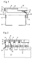
- Fig. 2
- eine Seitenansicht mit Teilschnitt einer Anordnung mit mehreren angebrachten Schutzhauben; und
- Fig. 3
- eine perspektivische Explosionsansicht einer Anordnung mit mehreren Modulen und einer Ausführungsform der Haube, die für den Schutz mehrerer Module ausgebildet ist.
- Fig. 1
- a plan view with partial section of the protective hood according to the invention;
- Fig. 2
- a side view with partial section of an arrangement with several attached protective hoods; and
- Fig. 3
- an exploded perspective view of an arrangement with several modules and an embodiment of the hood, which is designed for the protection of several modules.
Bei der in Fig. 1 gezeigten Anordnung ist die erfindungsgemäße Schutzhaube 30 auf einer sogenannten SID (Schraub-Isolierungs-Durchdringungs)-Leiste 10 angebracht.In the arrangement shown in FIG. 1, the
Die SID-Leiste 10 ist auf bekannte Art und Weise über Rasteinrichtungen 12 auf einen wannenartigen Träger 18 aufgesteckt, der in dem gezeigten Fall aus zwei, im Querschnitt L-förmigen Schenkeln besteht. Durch seitlich an der Anschlußleiste 10 angebrachte Kabelführungen 16 sind mehrere Kabel 20 zu dem in der Zeichnung oben befindlichen Bereich der Leiste 10 geführt, in dem sich die (nicht gezeigten) Kontakte der Anschlußleiste 10 befinden.The
Dieser Bereich wird von der erfindungsgemäßen Schutzhaube 30 umfaßt. Die Schutzhaube 30 ist im wesentlichen als ein hohler, an einer Seitenfläche offener Quader ausgebildet und weist einen oberen Deckelabschnitt 32 und vier seitliche Wandabschnitte 34 auf. Durch den Deckelabschnitt 32 und die seitlichen Wandabschnitte 34 ist ein Hohlraum oder eine Ausnehmung 36 festgelegt, in der im angebrachten Zustand der Schutzhaube 30 der obere, insbesondere der Kontaktbereich der Leiste 10 aufgenommen ist.This area is covered by the
In der gezeigten Ausführungsform ist die erfindungsgemäße Schutzhaube 30 an ihrem Randbereich 38 mit einem umlaufenden Dichtelement 40 versehen. In dem gezeigten Fall sind die seitlichen Wandabschnitte 34 so gestaltet, daß ihre freien Ränder 38, die den Rand der Ausnehmung 36 bilden, in der die Leiste 10 aufgenommen ist, im wesentlichen in einer Ebene liegen. Dies ist insbesondere in dem rechten Abschnitt von Fig. 1 anhand der weitgehend horizontalen Ausrichtung des Dichtelements 40 zu erkennen.In the embodiment shown, the
Das um den gesamten Rand der Schutzhaube 30 umlaufend ausgebildete Dichtelement 40 liegt zur Abdichtung gegen Staub weitgehend dichtend an dem zu schützenden Modul, in dem gezeigten Fall die Anschlußleiste 10, an. In der Schnittansicht des linken Bereichs von Fig. 1 ist das abdichtende Anliegen des Dichtelements 40 an der SID-Leiste 10 sichtbar.The sealing
Für die Ausbildung der gewünschten Schaltungsverbindungen sind mehrere Kabel 20 über die stirnseitig ausgebildeten Kabelführungen 16 zu den Kontakten der Anschlußleiste 10 geführt. Im rechten Bereich von Fig. 1 sind zwei solcher Kabel 20 angedeutet. Diese Kabel verlaufen üblicherweise, wie gezeigt, von den Kontakten über die Längsseiten der Leiste 10 zu den stirnseitigen Kabelführungen 16, oder sie verlaufen von den Kontakten über die Längsseiten der Leiste 10 zu dem Bereich unterhalb der Anschlußleiste 10 in dem wannenartigen Träger 18. Somit verlaufen die Kabel 20 aus dem abgedichteten Hohlraum 36 der Schutzhaube 30 heraus.For the formation of the desired circuit connections, a plurality of
Die erfindungsgemäße Schutzhaube 30 ist jedoch so gestaltet, daß auch an den Stellen, an denen Kabel 20 aus der Schutzhaube 30 herausgeführt werden, für eine zuverlässige Abdichtung gesorgt ist.However, the
Wie in Fig. 2 zu erkennen ist, liegt das elastische Dichtelement 40 dichtend an den Kabeln 20 an, die an den Längsseiten der Anschlußleisten 10 geführt sind. In der Schnittansicht des linken Bereichs von Fig. 2 ist der weitgehend U-förmige Querschnitt der einzelnen Schutzhauben 30 mit einem oberen Deckelabschnitt 32 und seitlichen Wandabschnitten 34 zu erkennen. Die in Fig. 2 sichtbaren Wandabschnitte 34 sind die längsseitigen Wandabschnitte der Schutzhaube 30, die im wesentlichen parallel zu der Längserstreckung der zu schützenden Anschlußleiste 10 verlaufen. An den unteren Rändern 38 der längsseitigen Wandabschnitte 34 ist im Querschnitt das elastische Dichtelement 40 zu erkennen, das um den gesamten Rand umlaufend ausgebildet ist und für die Abdichtung gegen Staub an den Oberflächen des Moduls 10 anliegt.As can be seen in FIG. 2, the
Wie in Fig. 2 im Querschnitt deutlich wird, durchdringen die Kabel 20 das Dichtelement 40 an den Längsseiten der Anschlußleiste 10, so daß sich an denjenigen Stellen, an denen Kabel aus dem Inneren 36 der Schutzhaube 30 herausgeführt werden, das Dichtelement leicht verformt. Dadurch liegt das Dichtelement sowohl an den Oberflächen des Modules als auch an den Kabeln 20 an, so daß kein Staub und keine aggressive Umgebungsluft eindringen kann. Das gezeigte und beschriebene Dichtelement 40 kann z.B. in Form einer Dichtlippe ausgebildet sein und an die Schutzhaube 30 sowohl geklebt, formschlüssig angesteckt oder im 2K-Spritzgußverfahren eingebracht werden.As is clear in cross section in FIG. 2, the
Alternativ kann der Rand 38 der Schutzhaube 30 mit einer entsprechenden Kontur versehen sein oder es können von diesem heraustrennbare Teilstücke entfernt worden sein, so daß Kabel durch die Ausbrüche geführt werden können, und eine weitgehende Abdichtung gegen das Eindringen von Staub durch das Zusammenwirken der Kontur oder den Rändern der Ausbrüche mit den Kabeln 20 und den Oberflächen des Moduls 10 erreicht wird.Alternatively, the
Dadurch sorgt die erfindungsgemäße Schutzhaube 30 nicht nur für einen wirksamen Schutz gegen Staub, sondern auch gegen sonstige ungünstige Umwelteinflüsse, wie Luftfeuchtigkeit und in der Luft enthaltene aggressive Stoffe, wie z.B. Salz.As a result, the
In Fig. 3 ist eine andere Ausführung der erfindungsgemäßen Haube gezeigt, die wiederum der Abdeckung und Abdichtung von mehreren Modulen 10 dient. In der perspektivischen Ansicht von Fig. 3 ist die Anbringung der Module 10 auf wannenartigen Trägern 18 zu erkennen, wobei, wie gezeigt, üblicherweise die länglichen Module 10 zueinander parallel auf die wannenartigen Träger 18 aufgesteckt werden. Es sind ferner an den Modulen 10 ausgebildete seitliche und frontale Kabelführungen 14 gezeigt, über welche die Kabel zu den in den oberen Bereichen der Module 10 befindlichen Kontakte geführt werden.3 shows another embodiment of the hood according to the invention, which in turn covers and seals serves
Dem Schutz dieses Bereichs der Kontakte dient die gezeigte Haube 50, die in dem gezeigten Fall zweistückig ausgebildet ist und aus einem schachtelartigen Körper 52 und einem Dichtungselement 54 besteht. Der Körper 52, der an seiner (nicht gezeigten) Unterseite offen ist, umfaßt im wesentlichen die oberen Bereiche sämtlicher zu schützender Module 10 und deckt die Kontaktbereiche der Module 10 von oben und von den Seiten her gegen das Eindringen von Staub und weitgehend gegen das Eindringen von feuchter Luft ab.To protect this area of the contacts, the
Der Abdichtung von unten dient bei der gezeigten Ausführungsform der Haube 50 das Dichtelement 54, das in Form eines Rahmens mit mehreren Ausnehmungen 56 gestaltet ist. Die Ausnehmungen 56 sind an die Form und Größe der zu schützenden Module 10 derart angepaßt, daß die umlaufenden Ränder der Ausnehmungen 56 im angebrachten Zustand weitgehend dichtend an den Oberflächen der Module 10 anliegen. Alternativ können diejenigen Ränder der Ausnehmungen 56, die sich im angebrachten Zustand der Module 10 und der wannenartigen Träger 18 an den Unterseiten der Module 10 befinden, nicht vollständig dichtend ausgebildet sein, um die Abführung von Kondenswasser, das sich in der Haube oder an den Modulen bei Temperaturschwankungen ablagert, zu ermöglichen. Zumeist werden die gezeigten wannenartigen Träger 18 in Verteilerkästen senkrecht angeordnet, so daß sich die aufgesteckten Module 10 in horizontaler Richtung von den wannenartigen Trägern 18 erstrecken. Dementsprechend ist im angebrachten Zustand die gezeigte Haube 50 derart ausgerichtet, daß ihre (in Fig. 3 oben befindliche) Deckelfläche sich vertikal erstreckend ausgerichtet ist und die gesamte Anordnung aus Modulen 10 und Trägern 18 insbesondere nach vornehin abdeckt.The seal from below is used in the embodiment of the
Aufgrund dieser Anordnung der Haube 50 in einer endgültigen Anbringstellung ist es zweckmäßig, an derjenigen kurzen (sich in Fig. 3 links bzw. rechts befindlichen) Seitenfläche, die sich im Anbringzustand der Haube 50 unten befindet, geeignete Kanäle oder sonstige Einrichtungen auszubilden, die eine gute Abführung von Kondenswasser ermöglichen. Für den Zusammenbau der gezeigten Haube 50 wird der Dichtungsrahmen 54 in dem Rand des Haubenkörpers 52 derart angebracht, daß zwischen dem Rand des Körpers 52 und dem äußeren Rand des Dichtungselements 54 zumindest größtenteils kein Luft- oder Staubdurchtritt mehr möglich ist. Dazu können am Rand des Körpers 52 z.B. zwei umlaufende kurze Leistenabschnitte ausgebildet sein, zwischen die das Dichtungselement 54 eingepaßt wird. Wahlweise können an der Unterseite der Haube, wie erwähnt, Öffnungen oder Kanäle vorgesehen sein, die den Austritt von Kondenswasser gestatten.Due to this arrangement of the
Nach der Verbindung des Dichtungselements 54 mit dem Haubenkörper 52 wird die komplette Haube 50 von oben (in Fig. 3 gezeigte Orientierung) bzw. von vorne (in einem endgültigen Anbringzustand im Verteilerkasten) aufgesteckt. Alternativ ist es denkbar, zunächst den Dichtungsrahmen 54 auf die Module aufzuschieben, und nachfolgend den Haubenkörper 52 auf den Dichtungsrahmen 54 aufzustecken und für eine Abdichtung zwischen dem Rand des Haubenkörpers 52 und dem Außenrand des Dichtungselements 54 zu sorgen. Es ist ferner möglich, in dem Fall, daß Arbeiten an den Modulen erforderlich sind, lediglich den Haubenkörper 52 von den Modulen 10 abzunehmen, und das Dichtungselement 54 an den Modulen 10 zu belassen. Dadurch wird erreicht, daß die Abdichtung zwischen den Rändern der Ausnehmungen 56 des Dichtungselements 54 und den Oberflächen der Module 10 nicht zerstört wird. Nach Abschluß der Arbeiten an den Modulen 10 wird der Haubenkörper 52 wieder aufgesteckt und dichtend mit dem Außenrand des Dichtungsrahmens 54 verbunden.After the sealing
Nach dem Aufstecken liegen in jedem Fall die Ränder der Ausnehmungen 56 des Dichtelements 54 dichtend, wahlweise an den Unterseiten der Module feuchtigkeitsdurchlässig, an, so daß auch aus dem Bereich unterhalb der Module 10 zwischen den wannenartigen Trägern 18 über die zwischen den Modulen 10 befindlichen Spalte kein Zutritt von Staub zu den Kontaktbereichen der Module 10 mehr möglich ist. Darüber hinaus sorgt der Körper 52, in den das Dichtungselement 54 staubdicht eingepaßt ist, für eine Abdeckung der Module 10 gegen Staubeintritt und die Luftzirkulation zu den Kontaktbereichen der Module 10.After plugging in, the edges of the
Für einen zuverlässigen Schutz gegen den Eintritt von Staub aus den Bereichen zwischen den Modulen 10 ist das Dichtelement 54 bevorzugt elastisch ausgebildet, so daß die Ränder der Ausnehmungen 56, die hinsichtlich ihrer Größe an die zu schützenden Module 10 angepaßt gestaltet sind, sich beim Anliegen an den Oberflächen der Module 10 ein wenig verformen und zuverlässig an den Modulen 10 anliegen. Dabei kann die Verformung sich auch dergestalt einstellen, daß jegliche Kabel, die an den Oberflächen des Moduls 10 anliegend zu den Kontakten des Moduls 10 geführt werden, für eine entsprechende Verformung der Ränder der Ausnehmungen 56 sorgen, die nunmehr abschnittsweise an den Oberflächen des Moduls 10 und abschnittsweise an eingeführten Kabeln anliegen. Durch die elastische Gestaltung des Dichtungselements 54 können sich die Ränder der Ausnehmungen 56 derart an eingeführte Kabel anpassen, daß auch in denjenigen Bereichen, in denen Kabel über die Oberflächen des Moduls 10 eingeführt sind, eine zuverlässige Abdichtung erfolgt.For reliable protection against the entry of dust from the areas between the
Die gezeigte Ausführungsform einer Haube 50 ist insbesondere deshalb vorteilhaft, weil als Haubenkörper 52 grundsätzlich bekannte Hauben für Module der Telekommunikationstechnik verwendet werden können. Gemäß der Erfindung wird ein Haubenkörper 52 in vorteilhafter Weise mit einem Dichtungselement 54 verbunden, um erstmalig eine vollständige Abdichtung gegen Staub und Umwelteinflüsse zu erreichen. Ferner ist die erfindungsgemäße Haube 50 so gestaltet, daß Bauteile, wie z.B. Trennstecker und Überspannungsschutzmagazine, die auf die Module 10 aufgesteckt sind, weiterhin verwendet werden können, weil sie im Inneren der Haube 50 bzw. ihres Körpers 52 nach wie vor Platz finden.The embodiment of a
Claims (19)
dadurch gekennzeichnet, daß
characterized in that
Applications Claiming Priority (2)
| Application Number | Priority Date | Filing Date | Title |
|---|---|---|---|
| DE29607356U | 1996-04-23 | ||
| DE29607356U DE29607356U1 (en) | 1996-04-23 | 1996-04-23 | Protective cover for modules in telecommunications technology |
Publications (3)
| Publication Number | Publication Date |
|---|---|
| EP0804043A2 true EP0804043A2 (en) | 1997-10-29 |
| EP0804043A3 EP0804043A3 (en) | 2000-03-08 |
| EP0804043B1 EP0804043B1 (en) | 2005-07-20 |
Family
ID=8022997
Family Applications (1)
| Application Number | Title | Priority Date | Filing Date |
|---|---|---|---|
| EP96119547A Expired - Lifetime EP0804043B1 (en) | 1996-04-23 | 1996-12-05 | Protective cover for modules in telecommunication technology |
Country Status (5)
| Country | Link |
|---|---|
| EP (1) | EP0804043B1 (en) |
| BR (1) | BR9700821A (en) |
| DE (2) | DE29607356U1 (en) |
| PL (1) | PL180904B1 (en) |
| RU (1) | RU2161383C2 (en) |
Families Citing this family (2)
| Publication number | Priority date | Publication date | Assignee | Title |
|---|---|---|---|---|
| RU2214699C2 (en) * | 2001-02-05 | 2003-10-20 | Акционерное общество закрытого типа "Контактор" | Gear for installation of printed circuit boards |
| JP7159798B2 (en) * | 2018-11-09 | 2022-10-25 | 株式会社デンソー | Protective covers and on-board equipment |
Family Cites Families (9)
| Publication number | Priority date | Publication date | Assignee | Title |
|---|---|---|---|---|
| DE2456802C3 (en) * | 1974-11-30 | 1980-12-11 | Robert Bosch Gmbh, 7000 Stuttgart | Electronic switchgear |
| GB2054968B (en) * | 1979-07-10 | 1984-05-16 | Plessey Co Ltd | Cover assemblies for electrical devices |
| US4734061A (en) * | 1986-12-31 | 1988-03-29 | Bell Communications Research, Inc. | Telecommunications terminal block |
| DE8717767U1 (en) * | 1987-12-23 | 1989-12-28 | Christoph Emmerich GmbH & Co KG, 6000 Frankfurt | Telecommunications device, in particular private branch exchange |
| SE9001157L (en) * | 1990-03-29 | 1991-09-16 | Mecman Ab | ELECTRICAL CONNECTING DEVICE FOR PILOT VALVES IN A VALVE DISASTER |
| FR2662030B1 (en) * | 1990-05-09 | 1992-09-04 | Aguera Michel | PROTECTIVE BOX FOR MISCELLANEOUS APPARATUS AND COMPONENTS. |
| FR2670055B1 (en) * | 1990-11-30 | 1993-01-15 | Cit Alcatel | PROTECTION AGAINST ELECTROMAGNETIC DISTURBANCES, FOR ELECTRICAL CONNECTION DEVICE. |
| US5296646A (en) * | 1992-04-03 | 1994-03-22 | The Whitaker Corporation | Protector module for telephone line junction box |
| DE9420759U1 (en) * | 1994-12-27 | 1995-05-24 | Siemens AG, 80333 München | Communication system |
-
1996
- 1996-04-23 DE DE29607356U patent/DE29607356U1/en not_active Expired - Lifetime
- 1996-12-05 EP EP96119547A patent/EP0804043B1/en not_active Expired - Lifetime
- 1996-12-05 DE DE59611248T patent/DE59611248D1/en not_active Expired - Fee Related
- 1996-12-20 RU RU96124078/09A patent/RU2161383C2/en not_active IP Right Cessation
- 1996-12-20 PL PL96317630A patent/PL180904B1/en not_active IP Right Cessation
-
1997
- 1997-01-30 BR BR9700821A patent/BR9700821A/en active Search and Examination
Non-Patent Citations (1)
| Title |
|---|
| None |
Also Published As
| Publication number | Publication date |
|---|---|
| DE59611248D1 (en) | 2005-08-25 |
| DE29607356U1 (en) | 1997-08-28 |
| BR9700821A (en) | 1998-07-07 |
| EP0804043B1 (en) | 2005-07-20 |
| PL180904B1 (en) | 2001-04-30 |
| PL317630A1 (en) | 1997-10-27 |
| EP0804043A3 (en) | 2000-03-08 |
| RU2161383C2 (en) | 2000-12-27 |
Similar Documents
| Publication | Publication Date | Title |
|---|---|---|
| DE4344659C1 (en) | Filter fan for fitting to splashproof housings or switchgear cabinets (electronics cabinets) | |
| DE20211002U1 (en) | Module for an electrical device, in particular fieldbus module | |
| WO2001029931A1 (en) | Shielded plug-in connector | |
| DE1861066U (en) | THREE-DIMENSIONAL CIRCUIT ARRANGEMENT WITH BLOCK-SHAPED CIRCUIT ASSEMBLIES THAT CAN BE SLIDED INTO A FRAME. | |
| DE69318331T2 (en) | Telephone distribution element, in particular connection terminal strip | |
| DE3830133A1 (en) | VENTILATED, SPLASH-PROOF HOUSING ASSEMBLY FOR ELECTRICAL COMPONENTS | |
| DE4322535A1 (en) | Electrical terminals having plug-in transverse links | |
| DE4223935C2 (en) | Dust and water protected electronic device | |
| DE102008062250A1 (en) | Installation switching device with a Isollierstoffgehäuse | |
| DE10061940A1 (en) | Bus bar adapter has longitudinal channels on top for accommodating contact rails, closure cover with isolating protrusions for contactlessly terminating ends of contact rails | |
| EP0618758B1 (en) | Programmable control unit | |
| EP0804043A2 (en) | Protective cover for modules in telecommunication technology | |
| DE4447731C2 (en) | Electrical plug-in connector unit for motor vehicle engine fuses | |
| EP0116162A2 (en) | Device for pluggable mounting an electrical circuit carrier on an electrical apparatus or the like and method of manufacturing it | |
| EP0749180B1 (en) | Housing of connector plug | |
| EP0162960A1 (en) | Aeration arrangement | |
| DE3146608C2 (en) | Arrangement of a circuit board, a hybrid board and a holder | |
| DE4301602C1 (en) | Electrical connector part with synthetic housing - has guide rails leading from entry opening of admission chamber to plug-in opening for mating contact element | |
| DE3149387C2 (en) | ||
| CH663292A5 (en) | SWITCH CABINET. | |
| EP0498402B1 (en) | Cover for electrical socket or socket combination | |
| DE29618628U1 (en) | Shielded subrack | |
| DE9403212U1 (en) | Housing for receiving printed circuit boards | |
| DE4439673A1 (en) | Electronic circuit-board plug connector e.g. for installing in motor vehicle engine bay | |
| DE10324411B4 (en) | Electronic device |
Legal Events
| Date | Code | Title | Description |
|---|---|---|---|
| PUAI | Public reference made under article 153(3) epc to a published international application that has entered the european phase |
Free format text: ORIGINAL CODE: 0009012 |
|
| AK | Designated contracting states |
Kind code of ref document: A2 Designated state(s): CH DE ES FR GB GR LI SE |
|
| AX | Request for extension of the european patent |
Free format text: LT PAYMENT 961205 |
|
| PUAL | Search report despatched |
Free format text: ORIGINAL CODE: 0009013 |
|
| AK | Designated contracting states |
Kind code of ref document: A3 Designated state(s): CH DE ES FR GB GR LI SE |
|
| AX | Request for extension of the european patent |
Free format text: LT PAYMENT 19961205 |
|
| RIC1 | Information provided on ipc code assigned before grant |
Free format text: 7H 04Q 1/14 A, 7H 05K 5/02 B, 7H 01R 13/52 B |
|
| 17P | Request for examination filed |
Effective date: 20000425 |
|
| 17Q | First examination report despatched |
Effective date: 20031212 |
|
| GRAP | Despatch of communication of intention to grant a patent |
Free format text: ORIGINAL CODE: EPIDOSNIGR1 |
|
| GRAS | Grant fee paid |
Free format text: ORIGINAL CODE: EPIDOSNIGR3 |
|
| GRAA | (expected) grant |
Free format text: ORIGINAL CODE: 0009210 |
|
| AK | Designated contracting states |
Kind code of ref document: B1 Designated state(s): CH DE ES FR GB GR LI SE |
|
| AX | Request for extension of the european patent |
Extension state: LT |
|
| PG25 | Lapsed in a contracting state [announced via postgrant information from national office to epo] |
Ref country code: GB Free format text: LAPSE BECAUSE OF FAILURE TO SUBMIT A TRANSLATION OF THE DESCRIPTION OR TO PAY THE FEE WITHIN THE PRESCRIBED TIME-LIMIT Effective date: 20050720 |
|
| REG | Reference to a national code |
Ref country code: GB Ref legal event code: FG4D Free format text: NOT ENGLISH |
|
| REG | Reference to a national code |
Ref country code: CH Ref legal event code: EP |
|
| REF | Corresponds to: |
Ref document number: 59611248 Country of ref document: DE Date of ref document: 20050825 Kind code of ref document: P |
|
| PG25 | Lapsed in a contracting state [announced via postgrant information from national office to epo] |
Ref country code: SE Free format text: LAPSE BECAUSE OF FAILURE TO SUBMIT A TRANSLATION OF THE DESCRIPTION OR TO PAY THE FEE WITHIN THE PRESCRIBED TIME-LIMIT Effective date: 20051020 Ref country code: GR Free format text: LAPSE BECAUSE OF FAILURE TO SUBMIT A TRANSLATION OF THE DESCRIPTION OR TO PAY THE FEE WITHIN THE PRESCRIBED TIME-LIMIT Effective date: 20051020 |
|
| PG25 | Lapsed in a contracting state [announced via postgrant information from national office to epo] |
Ref country code: ES Free format text: LAPSE BECAUSE OF FAILURE TO SUBMIT A TRANSLATION OF THE DESCRIPTION OR TO PAY THE FEE WITHIN THE PRESCRIBED TIME-LIMIT Effective date: 20051031 |
|
| LTIE | Lt: invalidation of european patent or patent extension |
Effective date: 20050720 |
|
| PG25 | Lapsed in a contracting state [announced via postgrant information from national office to epo] |
Ref country code: LI Free format text: LAPSE BECAUSE OF NON-PAYMENT OF DUE FEES Effective date: 20051231 Ref country code: CH Free format text: LAPSE BECAUSE OF NON-PAYMENT OF DUE FEES Effective date: 20051231 |
|
| GBV | Gb: ep patent (uk) treated as always having been void in accordance with gb section 77(7)/1977 [no translation filed] |
Effective date: 20050720 |
|
| PLBE | No opposition filed within time limit |
Free format text: ORIGINAL CODE: 0009261 |
|
| STAA | Information on the status of an ep patent application or granted ep patent |
Free format text: STATUS: NO OPPOSITION FILED WITHIN TIME LIMIT |
|
| 26N | No opposition filed |
Effective date: 20060421 |
|
| PG25 | Lapsed in a contracting state [announced via postgrant information from national office to epo] |
Ref country code: DE Free format text: LAPSE BECAUSE OF NON-PAYMENT OF DUE FEES Effective date: 20060701 |
|
| REG | Reference to a national code |
Ref country code: CH Ref legal event code: PL |
|
| EN | Fr: translation not filed | ||
| PG25 | Lapsed in a contracting state [announced via postgrant information from national office to epo] |
Ref country code: FR Free format text: LAPSE BECAUSE OF FAILURE TO SUBMIT A TRANSLATION OF THE DESCRIPTION OR TO PAY THE FEE WITHIN THE PRESCRIBED TIME-LIMIT Effective date: 20060915 |
|
| PG25 | Lapsed in a contracting state [announced via postgrant information from national office to epo] |
Ref country code: FR Free format text: LAPSE BECAUSE OF FAILURE TO SUBMIT A TRANSLATION OF THE DESCRIPTION OR TO PAY THE FEE WITHIN THE PRESCRIBED TIME-LIMIT Effective date: 20050720 |