EP0803953B1 - Kabelverschraubung - Google Patents
Kabelverschraubung Download PDFInfo
- Publication number
- EP0803953B1 EP0803953B1 EP97106047A EP97106047A EP0803953B1 EP 0803953 B1 EP0803953 B1 EP 0803953B1 EP 97106047 A EP97106047 A EP 97106047A EP 97106047 A EP97106047 A EP 97106047A EP 0803953 B1 EP0803953 B1 EP 0803953B1
- Authority
- EP
- European Patent Office
- Prior art keywords
- contact
- cable
- cable gland
- accordance
- connection piece
- Prior art date
- Legal status (The legal status is an assumption and is not a legal conclusion. Google has not performed a legal analysis and makes no representation as to the accuracy of the status listed.)
- Expired - Lifetime
Links
- 210000004907 gland Anatomy 0.000 title claims description 41
- 239000004020 conductor Substances 0.000 claims description 9
- 230000000717 retained effect Effects 0.000 claims 2
- 230000006835 compression Effects 0.000 claims 1
- 238000007906 compression Methods 0.000 claims 1
- 230000000284 resting effect Effects 0.000 claims 1
- 239000002184 metal Substances 0.000 abstract 1
- 241000446313 Lamella Species 0.000 description 6
- 239000000463 material Substances 0.000 description 5
- 230000000694 effects Effects 0.000 description 2
- 238000004519 manufacturing process Methods 0.000 description 2
- 239000012858 resilient material Substances 0.000 description 2
- 241001620634 Roger Species 0.000 description 1
- 230000015572 biosynthetic process Effects 0.000 description 1
- 230000005489 elastic deformation Effects 0.000 description 1
- 239000013013 elastic material Substances 0.000 description 1
- 230000002349 favourable effect Effects 0.000 description 1
- 238000003780 insertion Methods 0.000 description 1
- 230000037431 insertion Effects 0.000 description 1
- 238000007789 sealing Methods 0.000 description 1
Images
Classifications
-
- H—ELECTRICITY
- H02—GENERATION; CONVERSION OR DISTRIBUTION OF ELECTRIC POWER
- H02G—INSTALLATION OF ELECTRIC CABLES OR LINES, OR OF COMBINED OPTICAL AND ELECTRIC CABLES OR LINES
- H02G15/00—Cable fittings
- H02G15/02—Cable terminations
- H02G15/04—Cable-end sealings
Definitions
- the invention relates to a cable gland comprising a connecting piece which can be connected to a housing, a seal that can be inserted into an interior of the nozzle and a pressure element that can be screwed to the socket, which opens the seal in the sense of applying it to one by the cable gland acts on the lead-through cable, and a shield contact element arranged in the socket, which is in electrical connection with the nozzle and by means of one reaching in the direction of the cable that can be passed through Contact bracket an inner conductor area of the cable enclosing cable shield with a first contact point can contact.
- the invention is therefore based on the object of a cable gland to improve the generic type in such a way that the shield contact element is easy to assemble.
- This task is done with a cable gland at the beginning described type according to the invention solved in that the Shield contact element regardless of the seal of one end of the nozzle on the housing side can be used in these electrical contact with the nozzle is possible and that Shield contact element can be fixed locally in the socket.
- the shield contact element to be trained in a simple manner can, a defined positioning of the shield contact element to reach in the nozzle.
- the advantage of the solution according to the invention is also there see that through the shield contact element arranged in the socket a direct connection between the nozzle and the cable shield surrounding the inner conductor area of the cable can be produced, but the cable shield is not must be released from the inner conductor area of the cable, but only a cable outer sheath surrounding the cable shield is remove.
- the shield contact element can be fixed to the nozzle via a snap connection.
- the shield contact element can itself directly in the socket, for example, by locally fixing the support part in the Neck, be held.
- the shield contact element on an insert that can be inserted into the socket is held, since such a solution has the advantage that positioning in a simple manner via the insert of the shield contact element in the socket is accessible.
- the insert can be made of the same material or made of other material and in a different form be as the shield contact element, which is preferably made of made according to curved metallic flat material is.
- the insert part is preferably a plastic part.
- the shield contact element Locally fixable in the socket by means of the insert is, so that the insert part is designed in a simple manner can be a defined positioning of the To achieve shield contact element in the socket.
- the insert part can be fixed to the nozzle via a snap connection.
- the shield contact element can be particularly favorable position that this through the on the insert seated support part is held on the insert part.
- the carrier part on the Insert part is fixed non-positively.
- the contact bracket can in principle be the most varied Have agility. It is particularly advantageous it when the contact bracket is in an approximately parallel to one Movable along the longitudinal axis of the cable gland is. This level is to be understood as the level in which the contact bracket in all by the mobility conditional positions.
- the shield contact element has a single contact bracket.
- the shield contact element has several contact clips, which, for example, in constant angular distances around the longitudinal axis of the cable gland are arranged around.
- the contact clip has the Connecting piece directly contacted with a second contact point, so that a direct connection between the Cable shield and the socket can be produced.
- the contact clip has a knee-like bend that is between the first and the second contact point.
- the knee-like bend can be particularly advantageous exploit to generate a spring effect, namely by that the contact bracket at least in the area of the knee-like Bend made of a resilient material is.
- Such a knee-like bend then advantageously serves Way to the contact bracket both in the area of first contact point and in the area of the second contact point with sufficient strength to produce a good one electrical contact on the cable shield or socket to create.
- the contact bracket in the area of the first contact point has a skid-like bend, which a by the Contact bracket detachment of the cable shield when inserting prevented the same.
- the contact bracket in the area of the second Contact point has a bend, which serves to The best possible electrical even with low contact forces Contact through the smallest possible contact area receive.
- the shield contact element has one or more contact clips.
- the shield contact element has a support part on which the Contact bracket are held.
- the carrier part is preferably in the form of a ring curved part. Can be produced particularly expediently especially with the contact brackets, is the carrier part then when it is bent from a strip of flat material which is in the form of an open ring.
- the shield contact element is movable relative to the carrier part and that the carrier part is arranged fixed relative to the nozzle.
- Such a shield contact element has the advantage that on the one hand, there is the possibility, via the carrier part, that Positioning the contact bracket exactly in the socket, on the other hand the contact bracket relative to the carrier part to a sufficient extent are movable, even with varying thickness of the cable always good electrical contact between the cable shield and manufacture the nozzle.
- a particularly advantageous embodiment provides that the carrier part at a distance from an inner wall of the Stutzens lies and the contact bracket starting from the carrier part to one and then to the other contact point, so that the contact bracket starting from the carrier part both towards the inner wall of the nozzle as well as towards of the cable shield has sufficient room to move different dimensions due to elastic deformation balance.
- the cable gland according to the invention can in terms of Training the seal in a variety of ways be executed.
- a pressure element one pressure screw and one as a seal Pressing deformable in the axial direction and on one Pass-through cable can be brought to the seal to use.
- the pressure element is preferably as that Cap nut designed overlapping lamella basket, which on the lamellar basket acts so that the seal in Direction of a longitudinal axis of the cable gland pressed to the seal on a cable outer sheath of the passed Bring cable to the system.
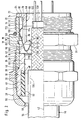
- Cable gland according to the invention comprises one as a whole with 10 designated electrically conductive nozzle, which has a cylindrical extension 12 with an external thread 14, with which the connector 10 into a wall 16, for example a housing can be screwed in.
- the neck further comprises a key surface section 18, which is provided with key surfaces 20 and on one an end 22 of the cylindrical projection 12 on the housing side opposite side directly on the cylindrical Approach 12 connects.
- a cylinder section 24 On a cylindrical projection 12 opposite Side of the flats section 18 of the socket 10 is a cylinder section 24 is provided, which has an external thread 26 wears. On the external thread 26 is one with 28 as a whole designated cap nut 28 with its internal thread 30 screwed.
- the cylinder section 24 serves to receive one as a whole with 32 designated seal carrier which with a retaining projection 34 engages in the cylinder section 24 and on one inner cylinder surface 36 of the same is guided. Further the seal carrier 32 is supported with a flange surface 38 on an end face facing away from the key surface section 18 40 of the cylinder section 24 and is thereby in Direction of a longitudinal axis 42 of the cable gland according to the invention against a shift in the direction of the key surface section 18 fixed.
- the seal carrier 32 further comprises a lamella basket 44, which in turn encloses a seal 46, the Seal 46 further by an inner shoulder 48 against one Shift in the direction of the longitudinal axis 42 to the key surface section 18 is fixable.
- the lamella basket 44 is in turn through an inclined surface 50 of the cap nut 28 acted upon, which with increasing Screwing the cap nut 28 onto the external thread 26 Slats of the slat basket 44 increasingly in the direction of Longitudinal axis 42 is deformed and thus that in the lamella basket 44 received seal 46 also so far in the direction of Longitudinal axis 42 moves that an inner passage 52 on a Cable outer surface 54 of a cable 56 with sealing Pressing can be applied.
- the cable 56 runs through one to the longitudinal axis 42 coaxial opening 58 of cap nut 28, then through the passage 52 of the seal 46 and then passes through an interior Breakthrough 60 of the seal carrier 32.
- Following the Seal carrier 32 extends the cable 56 through a Interior 62 of the nozzle 10, which is based on the Cylinder section 24 through the key surface section 18 and the cylindrical extension 12 to a housing side Opening 64 of the neck expands. From the housing side Opening 64 extends into interior 62 as a whole with 66 insert, which one Ring body 68 with a radially outer cylindrical Surface 70 and a radial over the cylindrical surface 70 has outwardly extending flange 72 which on a End face 74 of the housing-side end 22 of the connector 10 is present.
- the insert part 66 furthermore extends from the inner body 68 and extending in the direction of the longitudinal axis 42 Finger 76, which with a with respect to the longitudinal axis 42nd radially outward locking lug 78 in a preferably and lying in the area of the flats section 18 radially starting from the inner cylinder surface 36 externally extending groove 80 engages in the socket 10.
- the insert part 66 is thus from the housing end 22 insertable into the interior 62 of the socket 10, the Finger 76 elastically bendable in the direction of the longitudinal axis 42 are so that the lugs 78 thereof on the inner cylindrical Slide surface 36 from opening 64 to groove 80 and then engage in the groove 80 and thus one Form locking connection with this, while the Flange 72 abuts the end 22 of the connector 10 on the housing side.
- the insert part 66 carries one designated as a whole by 90 Shield contact element, which with an open Ring-shaped carrier part 92 on the cylindrical Surface 70 of the ring body 68 rests, the carrier part 92 a flat material strip bent into an open ring is.
- the support member 92 will protrude from the flange 72 Protrusions 94 held, which the support member 92 an outer side 96 facing away from the cylindrical surface 70 overlap, so that the carrier part in one between the projections 94 and the cylindrical surface 70 formed Slot is fixed.
- the carrier part 92 extends between the fingers 76 lying contact bracket 100, which faces away from the carrier part 92
- the first bracket arm 106 and a second bracket arm 108 are over a knee-like bend 110 connected to one another.
- the second bracket arm 108 connects to an inverted V-shaped Bend 112 and this is between a third, from Carrier part 92 with respect to the longitudinal axis 42 radially outwards leading arm 114 and the second arm 108.
- Each contact bracket 100 is used to manufacture an electrical Contact between a cable screen 120, which on an inner conductor area 122 of the cable 56 and enclosing it is present. Under the inner conductor area 122 all sub-components enclosed by the cable shield 120 Roger that. For this purpose, the contact bracket 100 touches the V-shaped one Bend 104 the cable shield 120 with a first one Contact point 124. Furthermore, each contact bracket extends 100 preferably in one through the longitudinal axis 42 level and is resilient in the plane movable, the bracket arms 106, 108 and 114 in the plane stay lying.
- the contact bracket 100 touches the nozzle 10 in the area its inner cylindrical surface 36 by means of the reverse V-shaped bend 112 to form a second contact point 126. Due to the shape of the contact bracket 100 lies between the first contact point 124 and the second Contact point 126 the knee-like bend 110 with that of this leading first bracket arm 106 and the second Arm 108, which is made of elastic material of the contact bracket a spring effect that the one hand Bend 104 against the cable shield 120 and the other hand Bend 112 against the inner cylindrical surface 36 of the Stubs 10 presses and thus the electrical contact in the Area of the first contact point 124 and the second contact point 126 maintains.
- the cable 56 inserted so far that the Cable outer sheath 130 still provided area in the passage 52nd the seal 46 lies so that by tightening the cap nut 28th the seal 46 for abutment on the outer cable surface 54 bringable and thus the cable 56 in the cable gland sealed on the one hand and at least non-positive on the other strain relief is fixable while at the same time an electrical contact between the cable shield 120 and the Stub 10 can be produced via the contact bracket 100.
Landscapes
- Details Of Connecting Devices For Male And Female Coupling (AREA)
- Insulated Conductors (AREA)
- Connector Housings Or Holding Contact Members (AREA)
- Superconductors And Manufacturing Methods Therefor (AREA)
- Measuring Fluid Pressure (AREA)
- Organic Insulating Materials (AREA)
- Communication Cables (AREA)
- Laying Of Electric Cables Or Lines Outside (AREA)
- Cable Accessories (AREA)
Description
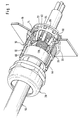
- Fig. 1
- eine perspektivische, teilweise aufgeschnittene Darstellung eines Ausführungsbeispiels der erfindungsgemäßen Kabelverschraubung und
- Fig. 2
- einen halbseitigen Längsschnitt durch das in Fig. 1 dargestellte Ausführungsbeispiel.
Claims (16)
- Kabelverschraubung umfassend einen mit einem Gehäuse verbindbaren Stutzen (10), eine in ein Inneres des Stutzens (10) einsetzbare Dichtung (46) sowie ein mit dem Stutzen (10) verschraubbares Druckelement (28), welches auf die Dichtung (46) im Sinne eines Anlegens derselben an ein durch die Kabelverschraubung hindurchführbares Kabel (56) einwirkt, ein in dem Stutzen (10) angeordnetes Schirmkontaktelement (90), welches in elektrischer Verbindung mit dem Stutzen (10) steht und mittels mindestens eines in Richtung des hindurchführbaren Kabels (56) reichenden Kontaktbügels (100) einen einen Innenleiterbereich (122) des Kabels (56) umschließenden Kabelschirm (120) mit einer ersten Kontaktstelle (124) zu kontaktieren vermag,
dadurch gekennzeichnet, daß der Stutzen (10) eine gehäuseseitige Öffnung (64) aufweist, daß das Schirmkontaktelement (90) unabhängig von der Dichtung (46) von einem gehäuseseitigen Ende (22) des Stutzens (10) in diesen einsetzbar und in elektrischen Kontakt mit dem Stutzen (10) bringbar ist, und daß das Schirmkontaktelement (90) in dem Stutzen (10) lokal fixierbar ist. - Kabelverschraubung nach Anspruch 1, dadurch gekennzeichnet, daß das Schirmkontaktelement (90) über eine Rastverbindung am Stutzen (10) lokal fixierbar ist.
- Kabelverschraubung nach einem der voranstehenden Ansprüche, dadurch gekennzeichnet, daß das Schirmkontaktelement (90) an einem in den Stutzen (10) einführbaren Einsatzteil (66) gehalten ist.
- Kabelverschraubung nach Anspruch 3, dadurch gekennzeichnet, daß das Einsatzteil (66) von einem gehäuseseitigen Ende (22) der Stutzens (10) in diesen einsetzbar ist.
- Kabelverschraubung nach Anspruch 3 oder 4, dadurch gekennzeichnet, daß das Schirmkontaktelement (90) mittels des Einsatzteils (66) in dem Stutzen (10) lokal fixierbar ist.
- Kabelverschraubung nach Anspruch 5, dadurch gekennzeichnet, daß das Einsatzteil (66) über eine Rastverbindung (78, 80) am Stutzen (10) fixierbar ist.
- Kabelverschraubung nach einem der Ansprüche 3 bis 6, dadurch gekennzeichnet, daß das Schirmkontaktelement (90) durch das an dem Einsatzteil (66) sitzende Trägerteil (92) am Einsatzteil gehalten ist.
- Kabelverschraubung nach einem der voranstehenden Ansprüche, dadurch gekennzeichnet, daß der Kontaktbügel (100) in einer ungefähr parallel zu einer Längsachse (42) der Kabelverschraubung verlaufenden Ebene bewegbar ist.
- Kabelverschraubung nach einem der voranstehenden Ansprüche, dadurch gekennzeichnet, daß das Schirmkontaktelement (90) mehrere Kontaktbügel (100) aufweist.
- Kabelverschraubung nach einem der voranstehenden Ansprüche, dadurch gekennzeichnet, daß der Kontaktbügel (100) den Stutzen (10) mit einer zweiten Kontaktstelle (126) unmittelbar kontaktiert.
- Kabelverschraubung nach einem der voranstehenden Ansprüche, dadurch gekennzeichnet, daß der Kontaktbügel (100) eine knieähnliche Umbiegung (110) aufweist, die zwischen der ersten (124) und der zweiten (126) Kontaktstelle liegt.
- Kabelverschraubung nach einem der voranstehenden Ansprüche, dadurch gekennzeichnet, daß der Kontaktbügel (100) im Bereich der ersten Kontaktstelle (124) eine Umbiegung (104) aufweist.
- Kabelverschraubung nach einem der voranstehenden Ansprüche, dadurch gekennzeichnet, daß der Kontaktbügel (100) im Bereich der zweiten Kontaktstelle (126) eine Umbiegung (112) aufweist.
- Kabelverschraubung nach einem der voranstehenden Ansprüche, dadurch gekennzeichnet, daß das Schirmkontaktelement (90) ein Trägerteil (92) aufweist, an welchem die Kontaktbügel (100) gehalten sind.
- Kabelverschraubung nach Anspruch 14, dadurch gekennzeichnet, daß der Kontaktbügel (100) relativ zum Trägerteil (92) bewegbar ist und daß das Trägerteil (92) relativ zum Stutzen (10) fixiert angeordnet ist.
- Kabelverschraubung nach Anspruch 14 oder 15, dadurch gekennzeichnet, daß das Trägerteil (92) im Abstand von einer Innenwand (36) des Stutzens (10) liegt und daß der Kontaktbügel von dem Trägerteil (92) ausgehend zu einer (124) und dann zur anderen (126) Kontaktstelle verläuft.
Priority Applications (1)
| Application Number | Priority Date | Filing Date | Title |
|---|---|---|---|
| EP00110095A EP1022836B1 (de) | 1996-04-19 | 1997-04-12 | Kabelverschraubung |
Applications Claiming Priority (3)
| Application Number | Priority Date | Filing Date | Title |
|---|---|---|---|
| DE19615602A DE19615602A1 (de) | 1996-04-19 | 1996-04-19 | Kabelverschraubung |
| DE19615602 | 1996-04-19 | ||
| US08/911,065 US5942730A (en) | 1996-04-19 | 1997-08-14 | Threaded cable joint |
Related Child Applications (1)
| Application Number | Title | Priority Date | Filing Date |
|---|---|---|---|
| EP00110095A Division EP1022836B1 (de) | 1996-04-19 | 1997-04-12 | Kabelverschraubung |
Publications (3)
| Publication Number | Publication Date |
|---|---|
| EP0803953A2 EP0803953A2 (de) | 1997-10-29 |
| EP0803953A3 EP0803953A3 (de) | 1998-04-15 |
| EP0803953B1 true EP0803953B1 (de) | 2000-12-27 |
Family
ID=26024930
Family Applications (2)
| Application Number | Title | Priority Date | Filing Date |
|---|---|---|---|
| EP00110095A Expired - Lifetime EP1022836B1 (de) | 1996-04-19 | 1997-04-12 | Kabelverschraubung |
| EP97106047A Expired - Lifetime EP0803953B1 (de) | 1996-04-19 | 1997-04-12 | Kabelverschraubung |
Family Applications Before (1)
| Application Number | Title | Priority Date | Filing Date |
|---|---|---|---|
| EP00110095A Expired - Lifetime EP1022836B1 (de) | 1996-04-19 | 1997-04-12 | Kabelverschraubung |
Country Status (8)
| Country | Link |
|---|---|
| US (1) | US5942730A (de) |
| EP (2) | EP1022836B1 (de) |
| AT (2) | ATE226370T1 (de) |
| DE (3) | DE19615602A1 (de) |
| DK (1) | DK1022836T3 (de) |
| ES (2) | ES2154856T3 (de) |
| PT (1) | PT1022836E (de) |
| SI (1) | SI1022836T1 (de) |
Cited By (1)
| Publication number | Priority date | Publication date | Assignee | Title |
|---|---|---|---|---|
| US9312672B2 (en) | 2013-09-26 | 2016-04-12 | Panduit Corp. | Threaded sleeve compressed split cable gland |
Families Citing this family (54)
| Publication number | Priority date | Publication date | Assignee | Title |
|---|---|---|---|---|
| JP3394175B2 (ja) * | 1998-01-13 | 2003-04-07 | 矢崎総業株式会社 | シールド電線の端末処理構造及び端末処理方法 |
| DE19801145A1 (de) * | 1998-01-14 | 1999-07-22 | Lapp U I Gmbh & Co Kg | Kabelverschraubung |
| DE10216379A1 (de) * | 2002-04-12 | 2003-10-30 | Conducta Endress & Hauser | Messeinrichtung für die Flüssigkeits-und/oder Gasanalyse |
| US6769933B2 (en) | 2002-11-27 | 2004-08-03 | Corning Gilbert Inc. | Coaxial cable connector and related methods |
| DE20219618U1 (de) | 2002-12-17 | 2003-04-30 | Knorr, Franz, 93176 Beratzhausen | Anschlußvorrichtung für Kabel bzw. Leitungen |
| US20050082828A1 (en) * | 2003-09-12 | 2005-04-21 | Wicks Jeffrey C. | Releasable connection assembly for joining tubing sections |
| DE10356386B3 (de) * | 2003-12-03 | 2005-05-25 | Pflitsch Gmbh & Co. Kg | Verschraubung für abgedichtete Kabeldurchführungen |
| DE102005017688B4 (de) * | 2005-04-08 | 2020-07-09 | Lapp Engineering & Co. | Kabeldurchführung mit Schirmkontaktelement |
| DE102006008457A1 (de) * | 2005-04-08 | 2006-10-12 | Lapp Engineering & Co. | Kabeldurchführung |
| DE102006062609A1 (de) | 2005-07-28 | 2008-07-03 | Hidde, Axel R., Dr. | Kabeldurch-/-einführungselement zum Dichten, Klemmen, Schirmen und Leiten |
| US7806139B2 (en) | 2006-01-20 | 2010-10-05 | Value Plastics, Inc. | Fluid conduit coupling assembly having male and female couplers with integral valves |
| DE102006043217C5 (de) | 2006-09-11 | 2010-07-29 | Bimed Teknik A.S., Büyükcekmece | Kabel- oder Schlauchverschraubung |
| US7507907B2 (en) | 2006-09-22 | 2009-03-24 | Lapp Engineering & Co. | Cable feed-through |
| KR100949611B1 (ko) | 2006-09-29 | 2010-03-25 | 랩 엔지니어링 앤드 컴퍼니 | 장치의 구멍용 인써트 |
| DE102007017918B4 (de) | 2007-04-13 | 2009-01-02 | Rittal Gmbh & Co. Kg | Befestigungsanordnung für eine Kabel- oder Schlauchverschraubung |
| DE102007052562B4 (de) | 2007-04-13 | 2022-02-17 | Bimed Teknik A.S. | Befestigungsanordnung mit einer Kabel- oder Schlauchverschraubung |
| DE102008019165A1 (de) * | 2008-04-17 | 2009-11-19 | Bimed Teknik A.S., Büyükcekmece | Kabelverschraubung, insbesondere für ein Abschirm- oder Erdungskabel |
| US8235426B2 (en) | 2008-07-03 | 2012-08-07 | Nordson Corporation | Latch assembly for joining two conduits |
| DE102009023646A1 (de) | 2009-05-25 | 2010-12-02 | Bimed Teknik A.S., Büyükcekmece | Kabel-/ Schlauchverschraubung |
| USD655393S1 (en) | 2009-06-23 | 2012-03-06 | Value Plastics, Inc. | Multi-port valve |
| US20110021069A1 (en) * | 2009-07-21 | 2011-01-27 | Yiping Hu | Thin format crush resistant electrical cable |
| DE202009013522U1 (de) * | 2009-10-07 | 2009-12-24 | Hummel Ag | Kabelverschraubung für ein abgeschirmtes Kabel |
| DE102009055641A1 (de) | 2009-11-25 | 2011-05-26 | Hidde, Axel R., Dr. | Elektrische Kontaktierungseinrichtung für Leitung und Abschirmung |
| USD650478S1 (en) | 2009-12-23 | 2011-12-13 | Value Plastics, Inc. | Female dual lumen connector |
| USD783815S1 (en) | 2009-12-09 | 2017-04-11 | General Electric Company | Male dual lumen bayonet connector |
| US10711930B2 (en) | 2009-12-09 | 2020-07-14 | Nordson Corporation | Releasable connection assembly |
| US9388929B2 (en) | 2009-12-09 | 2016-07-12 | Nordson Corporation | Male bayonet connector |
| CN102753876B (zh) | 2009-12-23 | 2015-07-22 | 诺信公司 | 具有一体式模制悬臂弹簧的按钮闩 |
| EP2516913B1 (de) | 2009-12-23 | 2014-09-17 | Nordson Corporation | Fluidverbinderverriegelungen mit profildurchführungen |
| EP2339216B1 (de) | 2009-12-23 | 2012-08-08 | LacTec GmbH | Leitungsdurchführung |
| EP2505116B1 (de) * | 2010-01-25 | 2014-02-26 | Olympus Medical Systems Corp. | Elektronisches endoskop |
| DE102011003071A1 (de) * | 2011-01-24 | 2012-07-26 | Lapp Engineering & Co. | Kabeldurchführung |
| DE202011002286U1 (de) * | 2011-02-02 | 2012-05-16 | Wiska Hoppmann & Mulsow Gmbh | Kabelverschraubunng mit Kontaktfeder |
| DE102011102566B4 (de) * | 2011-03-04 | 2016-09-15 | Amphenol-Tuchel Electronics Gmbh | Federkontaktelement |
| DE102011018993A1 (de) | 2011-04-28 | 2012-10-31 | Mc Technology Gmbh | Schirmkontaktfeder |
| USD699841S1 (en) | 2011-07-29 | 2014-02-18 | Nordson Corporation | Female body of connector for fluid tubing |
| USD698440S1 (en) | 2011-07-29 | 2014-01-28 | Nordson Corporation | Connector for fluid tubing |
| USD699840S1 (en) | 2011-07-29 | 2014-02-18 | Nordson Corporation | Male body of connector for fluid tubing |
| USD709612S1 (en) | 2011-12-23 | 2014-07-22 | Nordson Corporation | Female dual lumen connector |
| DE102012106592A1 (de) | 2012-07-20 | 2014-01-23 | Lapp Engineering & Co. | Kabeldurchführung |
| DE102013009184A1 (de) | 2013-05-31 | 2014-12-04 | Kostal Kontakt Systeme Gmbh | Kontaktelement |
| CN103579987B (zh) * | 2013-10-30 | 2016-02-17 | 森松(江苏)重工有限公司 | 一种防爆电缆接头密封方法 |
| BR112016015026A2 (pt) * | 2013-12-24 | 2017-08-08 | Ppc Broadband Inc | Um conector que possui um engatador de condutor interno |
| BR112017001928A2 (pt) | 2014-07-30 | 2017-11-28 | Corning Optical Comm Rf Llc | ?conectores de cabo coaxial com elementos de retenção condutor? |
| CN105609990A (zh) * | 2016-02-29 | 2016-05-25 | 孙萍 | 便调式电缆连接器 |
| CN106329460A (zh) * | 2016-08-31 | 2017-01-11 | 广州迈拓机电有限公司 | 一种电磁兼容屏蔽电缆接头 |
| USD838366S1 (en) | 2016-10-31 | 2019-01-15 | Nordson Corporation | Blood pressure connector |
| US10622799B2 (en) | 2017-02-14 | 2020-04-14 | Te Connectivity Corporation | Electrical cable splice |
| EP3716430A1 (de) * | 2019-03-27 | 2020-09-30 | ABB Schweiz AG | Verfahren zur bereitstellung von emv-schutz für stromkabelanordnung sowie durch besagtes verfahren hergestellte emv geschützte stromkabelanordnung |
| CN111934122B (zh) * | 2019-04-24 | 2024-04-05 | 哈廷电子有限公司及两合公司 | 一种公连接器和母连接器及包括其的连接器组件 |
| DE202019104919U1 (de) * | 2019-09-05 | 2020-12-08 | Wiska Hoppmann Gmbh | Befestigungselement für Kontaktierung von abgeschirmten Kabeln für Kabelverschraubungen |
| CN111244856B (zh) * | 2020-03-19 | 2025-02-11 | 崔春艳 | 一种电缆穿舱对接装置 |
| EP4315537A1 (de) * | 2021-03-30 | 2024-02-07 | Hellermanntyton (Pty) Limited | Kabelverschraubung |
| US20240072527A1 (en) * | 2022-08-26 | 2024-02-29 | Hubbell Incorporated | Self tensioned cable grounding device |
Family Cites Families (9)
| Publication number | Priority date | Publication date | Assignee | Title |
|---|---|---|---|---|
| DE598261C (de) * | 1932-02-14 | 1934-06-07 | Siemens Schuckertwerke Akt Ges | Anordnung fuer dieselelektrische Fahrzeuge mit selbsterregten Generatoren |
| CA1179029A (en) * | 1982-04-22 | 1984-12-04 | John B. Hutchison | Electric cable glands |
| DE3708493C1 (en) * | 1987-03-16 | 1988-06-09 | Kathrein Werke Kg | Connecting device for coaxial cables |
| GB2233838A (en) * | 1989-06-30 | 1991-01-16 | Hawke Cable Glands Ltd | Cable glands |
| US5059747A (en) * | 1989-12-08 | 1991-10-22 | Thomas & Betts Corporation | Connector for use with metal clad cable |
| DE4031553A1 (de) * | 1990-10-05 | 1992-04-09 | Schupa Elektro Gmbh & Co Kg | Einrichtung zur elektrischen kontaktherstellung |
| DE9204291U1 (de) * | 1992-03-30 | 1992-05-07 | ABB Patent GmbH, 6800 Mannheim | Kabelverschraubung |
| DE4238517A1 (de) * | 1992-11-14 | 1994-05-19 | Hummel Anton Verwaltung | Kabelverschraubung für Erdungs- oder Abschirm-Kabel |
| JP3211587B2 (ja) * | 1994-09-27 | 2001-09-25 | 住友電装株式会社 | シールド電線のアース構造 |
-
1996
- 1996-04-19 DE DE19615602A patent/DE19615602A1/de not_active Ceased
-
1997
- 1997-04-12 EP EP00110095A patent/EP1022836B1/de not_active Expired - Lifetime
- 1997-04-12 AT AT00110095T patent/ATE226370T1/de active
- 1997-04-12 ES ES97106047T patent/ES2154856T3/es not_active Expired - Lifetime
- 1997-04-12 SI SI9730425T patent/SI1022836T1/xx unknown
- 1997-04-12 EP EP97106047A patent/EP0803953B1/de not_active Expired - Lifetime
- 1997-04-12 AT AT97106047T patent/ATE198392T1/de active
- 1997-04-12 DE DE59702799T patent/DE59702799D1/de not_active Expired - Lifetime
- 1997-04-12 DE DE59708514T patent/DE59708514D1/de not_active Expired - Lifetime
- 1997-04-12 ES ES00110095T patent/ES2183762T3/es not_active Expired - Lifetime
- 1997-04-12 PT PT00110095T patent/PT1022836E/pt unknown
- 1997-04-12 DK DK00110095T patent/DK1022836T3/da active
- 1997-08-14 US US08/911,065 patent/US5942730A/en not_active Expired - Lifetime
Cited By (1)
| Publication number | Priority date | Publication date | Assignee | Title |
|---|---|---|---|---|
| US9312672B2 (en) | 2013-09-26 | 2016-04-12 | Panduit Corp. | Threaded sleeve compressed split cable gland |
Also Published As
| Publication number | Publication date |
|---|---|
| DE19615602A1 (de) | 1997-10-23 |
| ES2154856T3 (es) | 2001-04-16 |
| EP1022836B1 (de) | 2002-10-16 |
| SI1022836T1 (en) | 2003-02-28 |
| US5942730A (en) | 1999-08-24 |
| EP0803953A3 (de) | 1998-04-15 |
| EP1022836A3 (de) | 2001-12-05 |
| DE59702799D1 (de) | 2001-02-01 |
| ATE198392T1 (de) | 2001-01-15 |
| EP0803953A2 (de) | 1997-10-29 |
| PT1022836E (pt) | 2003-03-31 |
| EP1022836A2 (de) | 2000-07-26 |
| ES2183762T3 (es) | 2003-04-01 |
| DE59708514D1 (de) | 2002-11-21 |
| DK1022836T3 (da) | 2003-02-17 |
| ATE226370T1 (de) | 2002-11-15 |
Similar Documents
| Publication | Publication Date | Title |
|---|---|---|
| EP0803953B1 (de) | Kabelverschraubung | |
| DE19849227C1 (de) | Kabelhalterung | |
| EP2479857B1 (de) | Kabeldurchführung | |
| EP0598261B1 (de) | Kabelverschraubung für Erdungs- oder Abschirm-Kabel | |
| DE2425070C3 (de) | Elektrischer Steckverbinder für Koaxialkabel | |
| DE19510896C1 (de) | Abdichtende Kabeldurchführung für geschirmte Kabel | |
| EP1459411B1 (de) | Kabelanschluss | |
| DE19738517C1 (de) | Kabelverschraubung für Erdungs- oder Abschirmkabel mit einem gegen das Kabel preßbaren Klemmeinsatz | |
| EP2084783B1 (de) | Installationsschaltgerät und anschlussklemme für ein installationsschaltgerät | |
| EP1362393B1 (de) | Steckverbinder mit einem gehäuse und mit einem klemmeinsatz | |
| DE69309633T2 (de) | Geerdete Kabelverschraubung | |
| DE102008019165A1 (de) | Kabelverschraubung, insbesondere für ein Abschirm- oder Erdungskabel | |
| DE102008057473B4 (de) | Kabeldurchführung | |
| EP0803954B1 (de) | Kabelverschraubung | |
| EP1039578A2 (de) | Schalter | |
| EP0735614B1 (de) | Schraubklemme für elektrische Leiter | |
| EP0930687B1 (de) | Kabelverschraubung | |
| WO2003067138A1 (de) | Anschlusseinrichtung, anschlussstück und kontaktklammer für eine fluidleitung | |
| DE10117570A1 (de) | Elektrischer Kontakt sowie Lampenfassung und Anschluss- oder Verbindungsklemme mit mindestens einem solchen Kontakt | |
| DE102005017688B4 (de) | Kabeldurchführung mit Schirmkontaktelement | |
| DE19715070C2 (de) | Vorrichtung zum Befestigen von elektrischen Leitungen | |
| EP4254683B1 (de) | Rundsteckverbinder und verfahren zum herstellen eines rundsteckverbinders | |
| DE4443545B4 (de) | Steckverbinder | |
| DE4022678A1 (de) | Zugentlastung bei einem elektrischen steckverbinder | |
| DE10329772B4 (de) | Kabelanschlußeinrichtung |
Legal Events
| Date | Code | Title | Description |
|---|---|---|---|
| PUAI | Public reference made under article 153(3) epc to a published international application that has entered the european phase |
Free format text: ORIGINAL CODE: 0009012 |
|
| AK | Designated contracting states |
Kind code of ref document: A2 Designated state(s): AT BE CH DE DK ES FI FR GB GR IE IT LI LU MC NL PT SE |
|
| AX | Request for extension of the european patent |
Free format text: AL PAYMENT 970412;LT PAYMENT 970412;LV PAYMENT 970412;SI PAYMENT 970412 |
|
| PUAL | Search report despatched |
Free format text: ORIGINAL CODE: 0009013 |
|
| AK | Designated contracting states |
Kind code of ref document: A3 Designated state(s): AT BE CH DE DK ES FI FR GB GR IE IT LI LU MC NL PT SE |
|
| AX | Request for extension of the european patent |
Free format text: AL PAYMENT 970412;LT PAYMENT 970412;LV PAYMENT 970412;SI PAYMENT 970412 |
|
| 17P | Request for examination filed |
Effective date: 19980923 |
|
| 17Q | First examination report despatched |
Effective date: 19990305 |
|
| GRAG | Despatch of communication of intention to grant |
Free format text: ORIGINAL CODE: EPIDOS AGRA |
|
| 17Q | First examination report despatched |
Effective date: 19990305 |
|
| GRAG | Despatch of communication of intention to grant |
Free format text: ORIGINAL CODE: EPIDOS AGRA |
|
| GRAH | Despatch of communication of intention to grant a patent |
Free format text: ORIGINAL CODE: EPIDOS IGRA |
|
| GRAH | Despatch of communication of intention to grant a patent |
Free format text: ORIGINAL CODE: EPIDOS IGRA |
|
| GRAA | (expected) grant |
Free format text: ORIGINAL CODE: 0009210 |
|
| AK | Designated contracting states |
Kind code of ref document: B1 Designated state(s): AT BE CH DE DK ES FI FR GB GR IE IT LI LU MC NL PT SE |
|
| AX | Request for extension of the european patent |
Free format text: AL PAYMENT 19970412;LT PAYMENT 19970412;LV PAYMENT 19970412;SI PAYMENT 19970412 |
|
| LTIE | Lt: invalidation of european patent or patent extension | ||
| PG25 | Lapsed in a contracting state [announced via postgrant information from national office to epo] |
Ref country code: SE Free format text: THE PATENT HAS BEEN ANNULLED BY A DECISION OF A NATIONAL AUTHORITY Effective date: 20001227 Ref country code: NL Free format text: LAPSE BECAUSE OF FAILURE TO SUBMIT A TRANSLATION OF THE DESCRIPTION OR TO PAY THE FEE WITHIN THE PRESCRIBED TIME-LIMIT Effective date: 20001227 Ref country code: IE Free format text: LAPSE BECAUSE OF FAILURE TO SUBMIT A TRANSLATION OF THE DESCRIPTION OR TO PAY THE FEE WITHIN THE PRESCRIBED TIME-LIMIT Effective date: 20001227 Ref country code: FI Free format text: LAPSE BECAUSE OF FAILURE TO SUBMIT A TRANSLATION OF THE DESCRIPTION OR TO PAY THE FEE WITHIN THE PRESCRIBED TIME-LIMIT Effective date: 20001227 |
|
| REF | Corresponds to: |
Ref document number: 198392 Country of ref document: AT Date of ref document: 20010115 Kind code of ref document: T |
|
| REG | Reference to a national code |
Ref country code: CH Ref legal event code: EP |
|
| ITF | It: translation for a ep patent filed | ||
| GBT | Gb: translation of ep patent filed (gb section 77(6)(a)/1977) |
Effective date: 20010103 |
|
| REF | Corresponds to: |
Ref document number: 59702799 Country of ref document: DE Date of ref document: 20010201 |
|
| REG | Reference to a national code |
Ref country code: IE Ref legal event code: FG4D Free format text: GERMAN |
|
| ET | Fr: translation filed | ||
| RAP2 | Party data changed (patent owner data changed or rights of a patent transferred) |
Owner name: U.I. LAPP VERMOEGENSVERWALTUNGS GMBH & CO. KG |
|
| PG25 | Lapsed in a contracting state [announced via postgrant information from national office to epo] |
Ref country code: PT Free format text: LAPSE BECAUSE OF FAILURE TO SUBMIT A TRANSLATION OF THE DESCRIPTION OR TO PAY THE FEE WITHIN THE PRESCRIBED TIME-LIMIT Effective date: 20010327 Ref country code: DK Free format text: LAPSE BECAUSE OF FAILURE TO SUBMIT A TRANSLATION OF THE DESCRIPTION OR TO PAY THE FEE WITHIN THE PRESCRIBED TIME-LIMIT Effective date: 20010327 |
|
| PG25 | Lapsed in a contracting state [announced via postgrant information from national office to epo] |
Ref country code: GR Free format text: LAPSE BECAUSE OF FAILURE TO SUBMIT A TRANSLATION OF THE DESCRIPTION OR TO PAY THE FEE WITHIN THE PRESCRIBED TIME-LIMIT Effective date: 20010330 |
|
| PG25 | Lapsed in a contracting state [announced via postgrant information from national office to epo] |
Ref country code: LU Free format text: LAPSE BECAUSE OF NON-PAYMENT OF DUE FEES Effective date: 20010412 Ref country code: AT Free format text: LAPSE BECAUSE OF NON-PAYMENT OF DUE FEES Effective date: 20010412 |
|
| REG | Reference to a national code |
Ref country code: ES Ref legal event code: FG2A Ref document number: 2154856 Country of ref document: ES Kind code of ref document: T3 |
|
| PG25 | Lapsed in a contracting state [announced via postgrant information from national office to epo] |
Ref country code: MC Free format text: LAPSE BECAUSE OF NON-PAYMENT OF DUE FEES Effective date: 20010430 Ref country code: BE Free format text: LAPSE BECAUSE OF NON-PAYMENT OF DUE FEES Effective date: 20010430 |
|
| NLT2 | Nl: modifications (of names), taken from the european patent patent bulletin |
Owner name: U.I. LAPP VERMOEGENSVERWALTUNGS GMBH & CO. KG |
|
| NLV1 | Nl: lapsed or annulled due to failure to fulfill the requirements of art. 29p and 29m of the patents act | ||
| PG25 | Lapsed in a contracting state [announced via postgrant information from national office to epo] |
Ref country code: LI Free format text: LAPSE BECAUSE OF NON-PAYMENT OF DUE FEES Effective date: 20010511 Ref country code: CH Free format text: LAPSE BECAUSE OF NON-PAYMENT OF DUE FEES Effective date: 20010511 |
|
| BERE | Be: lapsed |
Owner name: U.I. LAPP G.M.B.H. & CO. K.G. Effective date: 20010430 |
|
| PLBE | No opposition filed within time limit |
Free format text: ORIGINAL CODE: 0009261 |
|
| STAA | Information on the status of an ep patent application or granted ep patent |
Free format text: STATUS: NO OPPOSITION FILED WITHIN TIME LIMIT |
|
| REG | Reference to a national code |
Ref country code: IE Ref legal event code: FD4D |
|
| REG | Reference to a national code |
Ref country code: CH Ref legal event code: PL |
|
| 26N | No opposition filed | ||
| REG | Reference to a national code |
Ref country code: GB Ref legal event code: IF02 |
|
| REG | Reference to a national code |
Ref country code: ES Ref legal event code: PC2A |
|
| REG | Reference to a national code |
Ref country code: FR Ref legal event code: TP |
|
| REG | Reference to a national code |
Ref country code: GB Ref legal event code: 732E |
|
| REG | Reference to a national code |
Ref country code: FR Ref legal event code: PLFP Year of fee payment: 20 |
|
| PGFP | Annual fee paid to national office [announced via postgrant information from national office to epo] |
Ref country code: DE Payment date: 20160421 Year of fee payment: 20 Ref country code: ES Payment date: 20160413 Year of fee payment: 20 Ref country code: GB Payment date: 20160421 Year of fee payment: 20 |
|
| PGFP | Annual fee paid to national office [announced via postgrant information from national office to epo] |
Ref country code: IT Payment date: 20160427 Year of fee payment: 20 Ref country code: FR Payment date: 20160421 Year of fee payment: 20 |
|
| REG | Reference to a national code |
Ref country code: DE Ref legal event code: R071 Ref document number: 59702799 Country of ref document: DE |
|
| REG | Reference to a national code |
Ref country code: GB Ref legal event code: PE20 Expiry date: 20170411 |
|
| PG25 | Lapsed in a contracting state [announced via postgrant information from national office to epo] |
Ref country code: GB Free format text: LAPSE BECAUSE OF EXPIRATION OF PROTECTION Effective date: 20170411 |
|
| REG | Reference to a national code |
Ref country code: ES Ref legal event code: FD2A Effective date: 20180508 |
|
| PG25 | Lapsed in a contracting state [announced via postgrant information from national office to epo] |
Ref country code: ES Free format text: LAPSE BECAUSE OF EXPIRATION OF PROTECTION Effective date: 20170413 |